EP1604419B1 - Black start method and apparatus for a fuel cell power plant, and fuel cell power plant with black start capability - Google Patents
Black start method and apparatus for a fuel cell power plant, and fuel cell power plant with black start capability Download PDFInfo
- Publication number
- EP1604419B1 EP1604419B1 EP04760756A EP04760756A EP1604419B1 EP 1604419 B1 EP1604419 B1 EP 1604419B1 EP 04760756 A EP04760756 A EP 04760756A EP 04760756 A EP04760756 A EP 04760756A EP 1604419 B1 EP1604419 B1 EP 1604419B1
- Authority
- EP
- European Patent Office
- Prior art keywords
- fuel cell
- cell stack
- reactant
- power
- supply
- Prior art date
- Legal status (The legal status is an assumption and is not a legal conclusion. Google has not performed a legal analysis and makes no representation as to the accuracy of the status listed.)
- Expired - Lifetime
Links
- 239000000446 fuel Substances 0.000 title claims abstract description 176
- 238000000034 method Methods 0.000 title claims description 19
- 241001672018 Cercomela melanura Species 0.000 title abstract description 7
- 239000007800 oxidant agent Substances 0.000 claims abstract description 61
- 230000001590 oxidative effect Effects 0.000 claims abstract description 61
- 239000000376 reactant Substances 0.000 claims description 76
- 239000003990 capacitor Substances 0.000 claims description 15
- 238000010926 purge Methods 0.000 claims description 13
- 239000012080 ambient air Substances 0.000 claims description 6
- 239000003570 air Substances 0.000 claims description 5
- 238000009825 accumulation Methods 0.000 abstract 1
- 238000010586 diagram Methods 0.000 description 4
- 238000012544 monitoring process Methods 0.000 description 4
- 230000004913 activation Effects 0.000 description 3
- QVGXLLKOCUKJST-UHFFFAOYSA-N atomic oxygen Chemical compound [O] QVGXLLKOCUKJST-UHFFFAOYSA-N 0.000 description 3
- 230000003750 conditioning effect Effects 0.000 description 3
- 230000010355 oscillation Effects 0.000 description 3
- 239000001301 oxygen Substances 0.000 description 3
- 229910052760 oxygen Inorganic materials 0.000 description 3
- IJGRMHOSHXDMSA-UHFFFAOYSA-N Atomic nitrogen Chemical compound N#N IJGRMHOSHXDMSA-UHFFFAOYSA-N 0.000 description 2
- 238000004146 energy storage Methods 0.000 description 2
- 238000010248 power generation Methods 0.000 description 2
- 239000013589 supplement Substances 0.000 description 2
- UFHFLCQGNIYNRP-UHFFFAOYSA-N Hydrogen Chemical compound [H][H] UFHFLCQGNIYNRP-UHFFFAOYSA-N 0.000 description 1
- 230000002950 deficient Effects 0.000 description 1
- 230000003111 delayed effect Effects 0.000 description 1
- 238000009792 diffusion process Methods 0.000 description 1
- 239000007789 gas Substances 0.000 description 1
- 239000001257 hydrogen Substances 0.000 description 1
- 229910052739 hydrogen Inorganic materials 0.000 description 1
- 229910052757 nitrogen Inorganic materials 0.000 description 1
- 239000000843 powder Substances 0.000 description 1
- 230000004044 response Effects 0.000 description 1
- XLYOFNOQVPJJNP-UHFFFAOYSA-N water Substances O XLYOFNOQVPJJNP-UHFFFAOYSA-N 0.000 description 1
Images


Classifications
-
- H—ELECTRICITY
- H01—ELECTRIC ELEMENTS
- H01M—PROCESSES OR MEANS, e.g. BATTERIES, FOR THE DIRECT CONVERSION OF CHEMICAL ENERGY INTO ELECTRICAL ENERGY
- H01M8/00—Fuel cells; Manufacture thereof
- H01M8/04—Auxiliary arrangements, e.g. for control of pressure or for circulation of fluids
- H01M8/04082—Arrangements for control of reactant parameters, e.g. pressure or concentration
- H01M8/04089—Arrangements for control of reactant parameters, e.g. pressure or concentration of gaseous reactants
-
- H—ELECTRICITY
- H01—ELECTRIC ELEMENTS
- H01M—PROCESSES OR MEANS, e.g. BATTERIES, FOR THE DIRECT CONVERSION OF CHEMICAL ENERGY INTO ELECTRICAL ENERGY
- H01M16/00—Structural combinations of different types of electrochemical generators
- H01M16/003—Structural combinations of different types of electrochemical generators of fuel cells with other electrochemical devices, e.g. capacitors, electrolysers
- H01M16/006—Structural combinations of different types of electrochemical generators of fuel cells with other electrochemical devices, e.g. capacitors, electrolysers of fuel cells with rechargeable batteries
-
- H—ELECTRICITY
- H01—ELECTRIC ELEMENTS
- H01M—PROCESSES OR MEANS, e.g. BATTERIES, FOR THE DIRECT CONVERSION OF CHEMICAL ENERGY INTO ELECTRICAL ENERGY
- H01M8/00—Fuel cells; Manufacture thereof
- H01M8/02—Details
- H01M8/0202—Collectors; Separators, e.g. bipolar separators; Interconnectors
- H01M8/0258—Collectors; Separators, e.g. bipolar separators; Interconnectors characterised by the configuration of channels, e.g. by the flow field of the reactant or coolant
-
- H—ELECTRICITY
- H01—ELECTRIC ELEMENTS
- H01M—PROCESSES OR MEANS, e.g. BATTERIES, FOR THE DIRECT CONVERSION OF CHEMICAL ENERGY INTO ELECTRICAL ENERGY
- H01M8/00—Fuel cells; Manufacture thereof
- H01M8/04—Auxiliary arrangements, e.g. for control of pressure or for circulation of fluids
- H01M8/04223—Auxiliary arrangements, e.g. for control of pressure or for circulation of fluids during start-up or shut-down; Depolarisation or activation, e.g. purging; Means for short-circuiting defective fuel cells
-
- H—ELECTRICITY
- H01—ELECTRIC ELEMENTS
- H01M—PROCESSES OR MEANS, e.g. BATTERIES, FOR THE DIRECT CONVERSION OF CHEMICAL ENERGY INTO ELECTRICAL ENERGY
- H01M8/00—Fuel cells; Manufacture thereof
- H01M8/04—Auxiliary arrangements, e.g. for control of pressure or for circulation of fluids
- H01M8/04223—Auxiliary arrangements, e.g. for control of pressure or for circulation of fluids during start-up or shut-down; Depolarisation or activation, e.g. purging; Means for short-circuiting defective fuel cells
- H01M8/04225—Auxiliary arrangements, e.g. for control of pressure or for circulation of fluids during start-up or shut-down; Depolarisation or activation, e.g. purging; Means for short-circuiting defective fuel cells during start-up
-
- H—ELECTRICITY
- H01—ELECTRIC ELEMENTS
- H01M—PROCESSES OR MEANS, e.g. BATTERIES, FOR THE DIRECT CONVERSION OF CHEMICAL ENERGY INTO ELECTRICAL ENERGY
- H01M8/00—Fuel cells; Manufacture thereof
- H01M8/04—Auxiliary arrangements, e.g. for control of pressure or for circulation of fluids
- H01M8/04298—Processes for controlling fuel cells or fuel cell systems
- H01M8/043—Processes for controlling fuel cells or fuel cell systems applied during specific periods
- H01M8/04302—Processes for controlling fuel cells or fuel cell systems applied during specific periods applied during start-up
-
- H—ELECTRICITY
- H01—ELECTRIC ELEMENTS
- H01M—PROCESSES OR MEANS, e.g. BATTERIES, FOR THE DIRECT CONVERSION OF CHEMICAL ENERGY INTO ELECTRICAL ENERGY
- H01M8/00—Fuel cells; Manufacture thereof
- H01M8/24—Grouping of fuel cells, e.g. stacking of fuel cells
- H01M8/2465—Details of groupings of fuel cells
- H01M8/2483—Details of groupings of fuel cells characterised by internal manifolds
-
- H—ELECTRICITY
- H01—ELECTRIC ELEMENTS
- H01M—PROCESSES OR MEANS, e.g. BATTERIES, FOR THE DIRECT CONVERSION OF CHEMICAL ENERGY INTO ELECTRICAL ENERGY
- H01M8/00—Fuel cells; Manufacture thereof
- H01M8/04—Auxiliary arrangements, e.g. for control of pressure or for circulation of fluids
- H01M8/04298—Processes for controlling fuel cells or fuel cell systems
- H01M8/04694—Processes for controlling fuel cells or fuel cell systems characterised by variables to be controlled
- H01M8/04746—Pressure; Flow
- H01M8/04753—Pressure; Flow of fuel cell reactants
-
- H—ELECTRICITY
- H01—ELECTRIC ELEMENTS
- H01M—PROCESSES OR MEANS, e.g. BATTERIES, FOR THE DIRECT CONVERSION OF CHEMICAL ENERGY INTO ELECTRICAL ENERGY
- H01M8/00—Fuel cells; Manufacture thereof
- H01M8/04—Auxiliary arrangements, e.g. for control of pressure or for circulation of fluids
- H01M8/04298—Processes for controlling fuel cells or fuel cell systems
- H01M8/04694—Processes for controlling fuel cells or fuel cell systems characterised by variables to be controlled
- H01M8/04858—Electric variables
- H01M8/04865—Voltage
- H01M8/0488—Voltage of fuel cell stacks
-
- H—ELECTRICITY
- H01—ELECTRIC ELEMENTS
- H01M—PROCESSES OR MEANS, e.g. BATTERIES, FOR THE DIRECT CONVERSION OF CHEMICAL ENERGY INTO ELECTRICAL ENERGY
- H01M8/00—Fuel cells; Manufacture thereof
- H01M8/04—Auxiliary arrangements, e.g. for control of pressure or for circulation of fluids
- H01M8/04298—Processes for controlling fuel cells or fuel cell systems
- H01M8/04694—Processes for controlling fuel cells or fuel cell systems characterised by variables to be controlled
- H01M8/04858—Electric variables
- H01M8/04895—Current
- H01M8/0491—Current of fuel cell stacks
-
- Y—GENERAL TAGGING OF NEW TECHNOLOGICAL DEVELOPMENTS; GENERAL TAGGING OF CROSS-SECTIONAL TECHNOLOGIES SPANNING OVER SEVERAL SECTIONS OF THE IPC; TECHNICAL SUBJECTS COVERED BY FORMER USPC CROSS-REFERENCE ART COLLECTIONS [XRACs] AND DIGESTS
- Y02—TECHNOLOGIES OR APPLICATIONS FOR MITIGATION OR ADAPTATION AGAINST CLIMATE CHANGE
- Y02E—REDUCTION OF GREENHOUSE GAS [GHG] EMISSIONS, RELATED TO ENERGY GENERATION, TRANSMISSION OR DISTRIBUTION
- Y02E60/00—Enabling technologies; Technologies with a potential or indirect contribution to GHG emissions mitigation
- Y02E60/10—Energy storage using batteries
-
- Y—GENERAL TAGGING OF NEW TECHNOLOGICAL DEVELOPMENTS; GENERAL TAGGING OF CROSS-SECTIONAL TECHNOLOGIES SPANNING OVER SEVERAL SECTIONS OF THE IPC; TECHNICAL SUBJECTS COVERED BY FORMER USPC CROSS-REFERENCE ART COLLECTIONS [XRACs] AND DIGESTS
- Y02—TECHNOLOGIES OR APPLICATIONS FOR MITIGATION OR ADAPTATION AGAINST CLIMATE CHANGE
- Y02E—REDUCTION OF GREENHOUSE GAS [GHG] EMISSIONS, RELATED TO ENERGY GENERATION, TRANSMISSION OR DISTRIBUTION
- Y02E60/00—Enabling technologies; Technologies with a potential or indirect contribution to GHG emissions mitigation
- Y02E60/30—Hydrogen technology
- Y02E60/50—Fuel cells
Definitions
- the present invention relates to fuel cell electric power plants having black start capability, and black start systems and methods for fuel cell power plants.
- Fuel cells are known in the art. Fuel cells electrochemically react a fuel stream comprising hydrogen and an oxidant stream comprising oxygen to generate an electric current. Fuel cell electric power plants have been employed in transportation, portable and stationary applications.
- Stationary and portable applications include distributed power generation, back-up power, peak power, and uninterruptible power supply (UPS) systems.
- Distributed power generation relates to providing electrical power to residential, commercial and/or industrial customers instead of, or as a supplement to, the utility power grid.
- Power plants in such applications typically operate continuously. They are particularly suited to situations where the power grid is not available or sufficiently reliable.
- Peak power systems are intended to supplement the power grid, providing electrical power intermittently during periods of peak use when sufficient grid power may not be available or when the rate charged.by the utility increases.
- Back-up power and UPS systems provide electrical power during periods when the power grid, or other primary power source, is unavailable.
- Fuel cell power plants may also be employed in transportation applications, including cars, trucks, buses, trains, ships and aircraft.
- fuel cell electric power plants also comprise associated operating, monitoring and control systems, generally referred to as the balance of plant.
- the balance of plant typically includes reactant supply and power conditioning systems, and may also include various other systems for reactant humidification, temperature regulation, and operational monitoring, for example.
- the balance of plant usually also includes a control system for controlling the operation of the power plant.
- These systems include various electrical devices that require an electrical power source for operation, including blowers, compressors, regulators, sensors, powered valves and electronics, for example. Collectively, these devices represent an operational load that must be supplied with power before the fuel cell electric power plant can begin normal operation. Of course, once the fuel cell stack is producing a nominal output it can begin to power the operational load.
- Known fuel cell electric power plants may employ an electrical storage device, such as secondary batteries or super capacitors, to power the operational load until the fuel cell stack is operating and can provide sufficient power to do so.
- the electrical storage devices may provide power to external loads as well.
- US 6,266,576 B1 (“Okada et al. ”) disposes a fuel cell unit comprising a fuel cell, a fuel cell controller and a double-layer capacitor (or other electric energy storage means).
- the fuel cell controller receives electric energy from the double-layer capacitor or an external power source.
- the double-layer capacitor is the energy source, it is charged by the fuel cell prior to shutdown or refueling to ensure the double-layer capacitor has sufficient energy to power the controller on restart.
- the external power source may be used to charge the double-layer capacitor or supply the needed power to the controller directly. While this solution is suitable for certain applications, it does have some disadvantages.
- the power plant may be not be used for extended periods. Over time, such electrical storage devices lose electrical energy due to self-discharge, with the result that insufficient power is available to supply the operational load of the fuel cell stack, and the power plant will not start. Damaged or defective electrical storage devices may also fail to produce sufficient power for the operational load. Thus, without an external power supply the power plant will not be able to start. As another example, situations may arise in which the power plant is required to start but the electrical storage device, though functioning properly, has been discharged. This can occur when the reactant supply of the power plant is interrupted during operation, e. g. , the power plant "runs out of gas".
- the electrical storage device may be discharged supplying power to the external load, or may not have been adequately recharged before the fuel cell stack stopped producing power.
- the power plant will not be able to resume operation without an external power source to power the operational load.
- this can be a significant problem.
- EP 1 271 680 A2 discloses a fuel cell system and a method of operating a fuel cell system, wherein the fuel cell system comprises a fuel cell stack, a reactant supply system, an oxidant supply system and an electrical storage device electrically coupled to the fuel cell stack. Upon start-up of the fuel cell system the energy required for operating the reactant supply system and the oxidant supply system is supplied from the electrical storage device, wherein the oxidant supply as compared to the reactant supply is delayed for 5 to 10 seconds.
- the invention is directed to the problem to provide a fuel cell electric power plant that has black start capability, i. e., is able to start operation without requiring an external power source.
- the present invention addresses the disadvantages of conventional fuel cell power plants and provides further related advantages.
- a method of operating a fuel cell system to power a number of internal and external loads comprises: manually opening a reactant supply valve to supply a reactant from a reactant supply to a fuel cell stack; producing power from a reaction of the reactant and oxidant passively diffused into the fuel cell stack; accumulating the power produced from the reaction of the reactant and the oxidant passively diffused into the fuel cell stack in an electrical storage device; and supplying power from the electrical storage device to at least a first internal load after sufficient power has been accumulated in the electrical storage device to power at least the first internal load and before supplying power to the external load.
- a fuel cell system comprises: a fuel cell stack; a reactant supply system coupled to supply a flow of reactant to the fuel cell stack; an oxidant supply system coupled to supply a flow of oxidant to the fuel cell stack; and an electrical storage device electrically coupleable to the fuel cell stack to accumulate power produced from a reaction of the reactant and ambient air passively diffused into the fuel cell stack and further electrically coupled to supply the accumulated power to at least the oxidant supply system after sufficient power has been accumulated in the electrical storage device to power at least the oxidant supply systems.
- a fuel cell system to supply power to internal and external loads comprises: a fuel cell stack; a reactant supply system comprising at least a first reactant supply valve that is manually actuatable to supply a flow of reactant to the fuel cell stack; an oxidant supply system selectively having at least one element selectively operable to actively supply a flow of oxidant to the fuel cell stack; and an electrical storage device electrically coupleable to the fuel cell stack to accumulate power produced from a reaction of the reactant and oxidant passively diffused into the fuel cell stack and further electrically coupled to supply power to at least a first internal load before supplying power from the fuel cell stack to the external load.
- a fuel cell system comprises: a fuel cell stack; a reactant supply system selectively operable to supply a reactant to the fuel cell stack; an oxidant supply system selectively operable to actively supply a flow of oxidant to the fuel cell stack; and means for accumulating power produced by a reaction of the reactant and ambient oxidant in the fuel cell stack, and for powering the oxidant supply system to actively supply the flow of oxidant after sufficient power has been accumulated.
- a fuel cell system comprises: a fuel cell stack; a reactant supply system selectively operable to supply a reactant to the fuel cell stack; an oxidant supply system selectively operable to actively supply a flow of oxidant to the fuel cell stack; and means for accumulating power produced by a reaction of the reactant and oxidant passively diffused into the fuel cell stack, and for powering the oxidant supply system to actively supply the flow of oxidant after sufficient power has been accumulated.
- Figure 1 shows a fuel cell system 10 having a fuel cell stack 12 that may be electrically coupled to provide power to one or more external loads 14.
- the fuel cell stack 12 may include one or more fuel cells having associated resistance and capacitance, illustrated in Figure 1 by standard electrical schematic symbols, respectively.
- the fuel cell stack 12 receives a flow of fuel or reactant via a reactant supply system 16 and a flow of oxidant, for example air, via an oxidant supply system 18.
- the reactant supply system 16 may supply reactant from a reactant reservoir 20 which may be integrally formed with the fuel cell system 10, or may take the form of discrete units selectively coupleable to the fuel cell system 10 by way of appropriate valves and connectors 22.
- the reactant supply system 16 includes a first flow path between the reactant reservoir 20 and the fuel cell stack 12 that includes a first valve V1, and a second flow path between the reactant supply 20 and fuel cell stack 12 that includes a second valve V2.
- the second valve V2 is automatically operated under control of the fuel cell system 10, for example, via a solenoid S or other actuator.
- the first valve V1 is manually operable by way of a manually operated startup switch S1 to bypass the second valve V2, as illustrated by the associated broken line arrow.
- the oxidant supply system 18 includes at least one active component 24, for example a compressor, blower or fan, to actively supply an oxidant flow to the fuel cell stack 12.
- the fuel cell system 10 typically includes associated operating, monitoring and control systems generally referred to as the balance of plant 26.
- the balance of plant 26 may include the reactant supply system 16, oxidant supply system 18, power conditioning systems, and may include various other systems for reactant humidification, temperature regulation and/or operational monitoring.
- the balance of plant 26 may include a controller such as a microprocessor 28, memory 30 such as random access memory (“RAM”) and/or read only memory (“ROM”), and/or sensors 32 coupled to the microprocessor 28 to provide operating condition information regarding various components such as temperature, volumetric flow, and/or switch positions.
- the balance of plant may also include actuators, illustrated generally at 34, but also including, for example the solenoid S, for controlling various components of the fuel cell system 10.
- the various elements of the balance of plant 26 comprise internal loads of the fuel cell system 10, requiring power to operate, such as powder from the fuel cell stack 12 or an energy storage device.
- the fuel cell stack 12 may include an anode purge valve V3 that may be selectively operated to purge the anode of the fuel cell stack 12.
- the anode purge valve V3 may be manually actuated to allow the purging of the anode of the fuel cell stack 12 before sufficient power has been produced to automatically operate the anode purge valve V3.
- the anode purge valve V3 is additionally, or alternatively, automatically operated under control of the fuel cell system 10, for example, by way of the microprocessor 28.
- the fuel cell system 10 includes an electrical storage device 36, such as one or more super capacitors, electrically coupled in parallel with the fuel cell stack 12.
- an electrical storage device 36 such as one or more super capacitors, electrically coupled in parallel with the fuel cell stack 12.
- the electrical storage device 36 accumulates power, eventually supplying power to one or more components of the balance of plant after sufficient power has been accumulated.
- the electrical storage device 36 may accumulate power from the reaction of the reactant and ambient oxygen in the fuel cell stack 12, for example, oxidant that has passively seeped or diffused into the fuel cell stack 12 via the oxidant supply system 24.
- the electrical storage device 36 may provide power to the active element 24 of the oxidant supply system 18 to actively supply a flow of oxidant causing the fuel cell stack 12 to produce sufficient power to supply the internal and external loads.
- the fuel cell system 10 can be bootstrapped into operation.
- An optional resistance R1 may be electrically coupled in parallel across the electrical storage device 36 by the manual activation of the startup switch S1 to limit the in-rush of current to the electrical storage device 36 during system startup (e.g., electrical storage device charging).
- the resistance R1 may be electrically uncoupled from across the electrical storage device 36 once the fuel cell stack 12 is providing sufficient power to at least one of the internal loads, to increase the efficiency of the fuel cell system 10 by eliminating loss associated with the resistance R1.
- Diodes D1, D2 may be electrically coupled in the charging circuit to prevent the reverse flow of currents i4.
- a charging circuit switch S2 electrically couples and uncouples the electrical storage device 36 to the fuel cell stack 12 under control of the balance of plant, for example, under the control of the microprocessor 28 as illustrated by the associated broken line arrow.
- a load switch S3 electrically couples the load 14 to the fuel cell stack 12 when the fuel cell stack 12 is producing sufficient power to supply the external load 14 in addition to the internal loads.
- the load switch S3 is operated under control of the balance of plant, for example, under the control of the microprocessor 28 as illustrated by the associated broken line arrow.
- a load capacitance C1 may be electrically coupled across the load 14.
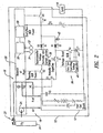
- FIG. 2 shows an alternative embodiment of the fuel cell system 10.
- This alternative embodiment and those alternative embodiments and other alternative described herein, are substantially similar to previously described embodiments, and common acts and structures are identified by the same reference numbers. Only significant differences in operation and structure are described below.
- the fuel cell system 10 of Figure 2 employs a flyback or boost converter 38 for conditioning the power supplied to the electrical storage device 36, for example, by boosting the voltage.
- the boost converter 38 may include an inductor L1 and a voltage controller 40, such as a very low operating voltage controller, employing pulse width modulation to operate a boost converter switch S4 based on voltage readings from a voltmeter 42 and current readings from an ammeter 44.
- Boost and flyback converters are well known electrical components that will not be described in detail in the interest of brevity.
- FIG 3 shows a fuel cell system 10 employing a charge pump or voltage multiplier circuit for boosting the voltage to the electrical storage device 36.
- the charging circuit may include an oscillator 46 controlling a first oscillation switch S4 according to a first timing signal and a second oscillation switch S5 according to a second timing signal which is the inverse of the first timing signal.
- a capacitance C2 is electrically coupled between the current limiting path (i.e. , path including resistance R1) and a common node between the oscillation switches S4, S5.
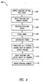
- FIG. 4 shows a method 400 of operating the fuel cell system 10.
- the reactant supply system 16 supplies reactant from the reactant reservoir 20 to the fuel cell stack 12.
- the reactant supply system 16 may supply reactant in response to the manual operation of the valve V1 by way of the startup switch S1.
- the activation of the startup switch S1 may also electrically couple the resistance R1 across the electrical storage device 36, for limiting the in-rush of current.
- the startup switch S1 may be such that it must be manually activated during the entire startup sequence. Alternatively, manual activation of the startup switch S1 may cause the startup switch S1 to remain closed for a defined duration equal to the typical duration of the startup sequence.
- the fuel cell stack 12 reacts the reactant and ambient oxidant to produce power.
- the ambient oxidant may passively reach the fuel cell stack via seepage or diffusion, for example, via the oxidant supply system 18 or through other channels.
- the circuitry of the fuel cell system 10 conditions the power resulting from the reaction between the reactant and the ambient oxidant.
- the resistance R1 ( Figure 1 ) may perform current limiting, and/or the boost or flyback converter ( Figure 2 ) or the charge pump ( Figure 3 ) may boost the voltage.
- the anode purge valve V3 may purge the anode as illustrated at 408.
- the electrical storage device 36 accumulates power. Once sufficient power has been accumulated, the electrical storage device 36 provides power to the balance of plant at 412. For example, the electrical storage device may provide power to one or more internal loads, such as the active element 24 of the oxidant supply system 18.
- the fuel cell stack 12 reacts the reactant supplied by the reactant supply system 16 with the oxidant actively supplied by the oxidant supply system 18, producing sufficient power for the internal and external-loads.
- the fuel cell system 10 closes switch S3 to electrically couple the load 14 to the fuel cell stack 12, successfully bootstrapping the fuel cell system 10.
- the startup switch S1 electrically uncouples the resistance R1 from across the electrical storage device 36 once the fuel cell stack is producing sufficient power to supply the external load 14, in order to increase the efficiency of the fuel cell system 10.
- the above operation can be described with reference to a NEXA TM fuel cell system available through Ballard Power Systems Inc. of Burnaby, Canada. Even without a cathode air pump operating, some oxygen or air will diffuse into the flow fields of the fuel cells and some nitrogen and/or water will diffuse out of the flow fields, allowing the fuel cell stack to produce approximately 4 Amps at 4 Volts or 16 Watts of power. The amount of power will depend on how open the cathode is to the ambient air surrounding the fuel cell stack.
- Fuel cell power plants having black start capability do not require an external power source for starting the balance of plant or to begin normal operation. This may be a significant advantage in several applications, including:
Landscapes
- Life Sciences & Earth Sciences (AREA)
- Engineering & Computer Science (AREA)
- Sustainable Development (AREA)
- Sustainable Energy (AREA)
- Chemical & Material Sciences (AREA)
- Chemical Kinetics & Catalysis (AREA)
- Electrochemistry (AREA)
- General Chemical & Material Sciences (AREA)
- Manufacturing & Machinery (AREA)
- Fuel Cell (AREA)
- Electric Propulsion And Braking For Vehicles (AREA)
- Pigments, Carbon Blacks, Or Wood Stains (AREA)
Abstract
Description
- The present invention relates to fuel cell electric power plants having black start capability, and black start systems and methods for fuel cell power plants.
- Fuel cells are known in the art. Fuel cells electrochemically react a fuel stream comprising hydrogen and an oxidant stream comprising oxygen to generate an electric current. Fuel cell electric power plants have been employed in transportation, portable and stationary applications.
- Stationary and portable applications include distributed power generation, back-up power, peak power, and uninterruptible power supply (UPS) systems. Distributed power generation relates to providing electrical power to residential, commercial and/or industrial customers instead of, or as a supplement to, the utility power grid. Power plants in such applications typically operate continuously. They are particularly suited to situations where the power grid is not available or sufficiently reliable. Peak power systems are intended to supplement the power grid, providing electrical power intermittently during periods of peak use when sufficient grid power may not be available or when the rate charged.by the utility increases. Back-up power and UPS systems provide electrical power during periods when the power grid, or other primary power source, is unavailable. Fuel cell power plants may also be employed in transportation applications, including cars, trucks, buses, trains, ships and aircraft.
- In addition to one or more fuel cell stacks, fuel cell electric power plants also comprise associated operating, monitoring and control systems, generally referred to as the balance of plant. The balance of plant typically includes reactant supply and power conditioning systems, and may also include various other systems for reactant humidification, temperature regulation, and operational monitoring, for example. The balance of plant usually also includes a control system for controlling the operation of the power plant.
- These systems include various electrical devices that require an electrical power source for operation, including blowers, compressors, regulators, sensors, powered valves and electronics, for example. Collectively, these devices represent an operational load that must be supplied with power before the fuel cell electric power plant can begin normal operation. Of course, once the fuel cell stack is producing a nominal output it can begin to power the operational load.
- Known fuel cell electric power plants may employ an electrical storage device, such as secondary batteries or super capacitors, to power the operational load until the fuel cell stack is operating and can provide sufficient power to do so. The electrical storage devices may provide power to external loads as well. For example,
US 6,266,576 B1 ("Okada et al. ") disposes a fuel cell unit comprising a fuel cell, a fuel cell controller and a double-layer capacitor (or other electric energy storage means). To start the fuel cell unit the fuel cell controller receives electric energy from the double-layer capacitor or an external power source. Where the double-layer capacitor is the energy source, it is charged by the fuel cell prior to shutdown or refueling to ensure the double-layer capacitor has sufficient energy to power the controller on restart. Alternatively, the external power source may be used to charge the double-layer capacitor or supply the needed power to the controller directly. While this solution is suitable for certain applications, it does have some disadvantages. - For example, in some applications the power plant may be not be used for extended periods. Over time, such electrical storage devices lose electrical energy due to self-discharge, with the result that insufficient power is available to supply the operational load of the fuel cell stack, and the power plant will not start. Damaged or defective electrical storage devices may also fail to produce sufficient power for the operational load. Thus, without an external power supply the power plant will not be able to start. As another example, situations may arise in which the power plant is required to start but the electrical storage device, though functioning properly, has been discharged. This can occur when the reactant supply of the power plant is interrupted during operation, e. g. , the power plant "runs out of gas". In this situation the electrical storage device may be discharged supplying power to the external load, or may not have been adequately recharged before the fuel cell stack stopped producing power. Unfortunately, once reactant supply is re-established, the power plant will not be able to resume operation without an external power source to power the operational load. For back-up, portable and vehicular applications, in particular, where another external power source may not be available, this can be a significant problem.
-
EP 1 271 680 A2 discloses a fuel cell system and a method of operating a fuel cell system, wherein the fuel cell system comprises a fuel cell stack, a reactant supply system, an oxidant supply system and an electrical storage device electrically coupled to the fuel cell stack. Upon start-up of the fuel cell system the energy required for operating the reactant supply system and the oxidant supply system is supplied from the electrical storage device, wherein the oxidant supply as compared to the reactant supply is delayed for 5 to 10 seconds. - The invention is directed to the problem to provide a fuel cell electric power plant that has black start capability, i. e., is able to start operation without requiring an external power source. The present invention addresses the disadvantages of conventional fuel cell power plants and provides further related advantages.
- The above mentioned problem is solved by a method of operating a fuel cell system according to
claim 1 and a fuel cell system according to claim 11. - In one aspect, a method of operating a fuel cell system comprising a fuel cell stack, a reactant supply system to selectively supply a reactant to the fuel cell stack, an oxidant supply system to selectively supply an oxidant to the fuel cell stack, and an electrical storage device electrically coupled to the fuel cell stack comprises: operating the reactant supply system to supply the reactant to the fuel cell stack; reacting the reactant and ambient air in the fuel cell stack to produce power; accumulating the power in the electrical storage device; and operating the oxidant supply system to supply an oxidant to the fuel cell stack after sufficient power has been accumulated in the electrical storage device to power at least the oxidant supply system.
- In another aspect, a method of operating a fuel cell system to power a number of internal and external loads comprises: manually opening a reactant supply valve to supply a reactant from a reactant supply to a fuel cell stack; producing power from a reaction of the reactant and oxidant passively diffused into the fuel cell stack; accumulating the power produced from the reaction of the reactant and the oxidant passively diffused into the fuel cell stack in an electrical storage device; and supplying power from the electrical storage device to at least a first internal load after sufficient power has been accumulated in the electrical storage device to power at least the first internal load and before supplying power to the external load.
- In still another aspect, a fuel cell system comprises: a fuel cell stack; a reactant supply system coupled to supply a flow of reactant to the fuel cell stack; an oxidant supply system coupled to supply a flow of oxidant to the fuel cell stack; and an electrical storage device electrically coupleable to the fuel cell stack to accumulate power produced from a reaction of the reactant and ambient air passively diffused into the fuel cell stack and further electrically coupled to supply the accumulated power to at least the oxidant supply system after sufficient power has been accumulated in the electrical storage device to power at least the oxidant supply systems.
- In a further aspect, a fuel cell system to supply power to internal and external loads comprises: a fuel cell stack; a reactant supply system comprising at least a first reactant supply valve that is manually actuatable to supply a flow of reactant to the fuel cell stack; an oxidant supply system selectively having at least one element selectively operable to actively supply a flow of oxidant to the fuel cell stack; and an electrical storage device electrically coupleable to the fuel cell stack to accumulate power produced from a reaction of the reactant and oxidant passively diffused into the fuel cell stack and further electrically coupled to supply power to at least a first internal load before supplying power from the fuel cell stack to the external load.
- In still a further aspect, a fuel cell system comprises: a fuel cell stack; a reactant supply system selectively operable to supply a reactant to the fuel cell stack; an oxidant supply system selectively operable to actively supply a flow of oxidant to the fuel cell stack; and means for accumulating power produced by a reaction of the reactant and ambient oxidant in the fuel cell stack, and for powering the oxidant supply system to actively supply the flow of oxidant after sufficient power has been accumulated.
- In yet a further aspect, a fuel cell system comprises: a fuel cell stack; a reactant supply system selectively operable to supply a reactant to the fuel cell stack; an oxidant supply system selectively operable to actively supply a flow of oxidant to the fuel cell stack; and means for accumulating power produced by a reaction of the reactant and oxidant passively diffused into the fuel cell stack, and for powering the oxidant supply system to actively supply the flow of oxidant after sufficient power has been accumulated.
- In the drawings, identical reference numbers identify similar elements or acts. The sizes and relative positions of elements in the drawings are not necessarily drawn to scale. For example, the shapes of various elements and angles are not drawn to scale, and some of these elements are arbitrarily enlarged and positioned to improve drawing legibility. Further, the particular shapes of the elements as drawn are not intended to convey any information regarding the actual shape of the particular elements, and have been solely selected for ease of recognition in the drawings.
-
Figure 1 is a schematic diagram of a fuel cell system comprising a fuel cell stack and appropriate hardware, software and/or logic to receive a supply of reactant from a reactant reservoir and to power internal and external loads according to one illustrated embodiment of the invention. -
Figure 2 is a schematic diagram of a fuel cell system according to a second illustrated embodiment of the invention. -
Figure 3 is a schematic diagram of a fuel cell system according to a third illustrated embodiment of the invention. -
Figure 4 is a flow diagram showing one exemplary illustrated method of operating the fuel cell stacks ofFigures 1 ,2 and3 . - In the following description, certain specific details are set forth in order to provide a thorough understanding of the various embodiment of the invention. However, one skilled in the art will understand that the invention may be practiced without these details. In other instances, well-known structures associated with fuel cells, fuel cell stacks, batteries and fuel cell systems have not been shown or described in detail to avoid unnecessarily obscuring description of the embodiments of the invention.
- Unless the context requires otherwise, throughout the specification and claims which follow, the word "comprise" and variations thereof, such as, "comprises" and "comprising" are to be construed in an open, inclusive sense, that is as "including, but not limited to."
- The headings provided herein are for convenience only and do not interpret the scope or meaning of the claimed invention.
-
Figure 1 shows afuel cell system 10 having afuel cell stack 12 that may be electrically coupled to provide power to one or moreexternal loads 14. Thefuel cell stack 12 may include one or more fuel cells having associated resistance and capacitance, illustrated inFigure 1 by standard electrical schematic symbols, respectively. - In use, the
fuel cell stack 12 receives a flow of fuel or reactant via areactant supply system 16 and a flow of oxidant, for example air, via anoxidant supply system 18. Thereactant supply system 16 may supply reactant from areactant reservoir 20 which may be integrally formed with thefuel cell system 10, or may take the form of discrete units selectively coupleable to thefuel cell system 10 by way of appropriate valves andconnectors 22. Thereactant supply system 16 includes a first flow path between thereactant reservoir 20 and thefuel cell stack 12 that includes a first valve V1, and a second flow path between thereactant supply 20 andfuel cell stack 12 that includes a second valve V2. The second valve V2 is automatically operated under control of thefuel cell system 10, for example, via a solenoid S or other actuator. The first valve V1 is manually operable by way of a manually operated startup switch S1 to bypass the second valve V2, as illustrated by the associated broken line arrow. Theoxidant supply system 18 includes at least oneactive component 24, for example a compressor, blower or fan, to actively supply an oxidant flow to thefuel cell stack 12. - In addition to the
fuel cell stack 12, thefuel cell system 10 typically includes associated operating, monitoring and control systems generally referred to as the balance ofplant 26. The balance ofplant 26 may include thereactant supply system 16,oxidant supply system 18, power conditioning systems, and may include various other systems for reactant humidification, temperature regulation and/or operational monitoring. For example, the balance ofplant 26 may include a controller such as amicroprocessor 28,memory 30 such as random access memory ("RAM") and/or read only memory ("ROM"), and/orsensors 32 coupled to themicroprocessor 28 to provide operating condition information regarding various components such as temperature, volumetric flow, and/or switch positions. The balance of plant may also include actuators, illustrated generally at 34, but also including, for example the solenoid S, for controlling various components of thefuel cell system 10. The various elements of the balance ofplant 26 comprise internal loads of thefuel cell system 10, requiring power to operate, such as powder from thefuel cell stack 12 or an energy storage device. - In some embodiments, the
fuel cell stack 12 may include an anode purge valve V3 that may be selectively operated to purge the anode of thefuel cell stack 12. In at least one embodiment, the anode purge valve V3 may be manually actuated to allow the purging of the anode of thefuel cell stack 12 before sufficient power has been produced to automatically operate the anode purge valve V3. In at least another embodiment, the anode purge valve V3 is additionally, or alternatively, automatically operated under control of thefuel cell system 10, for example, by way of themicroprocessor 28. - The
fuel cell system 10 includes anelectrical storage device 36, such as one or more super capacitors, electrically coupled in parallel with thefuel cell stack 12. One skilled in the art will recognize that other electrical storage devices, including storage batteries, may be suitable substitutes for super capacitors. Theelectrical storage device 36 accumulates power, eventually supplying power to one or more components of the balance of plant after sufficient power has been accumulated. For example, theelectrical storage device 36 may accumulate power from the reaction of the reactant and ambient oxygen in thefuel cell stack 12, for example, oxidant that has passively seeped or diffused into thefuel cell stack 12 via theoxidant supply system 24. As explained more fully below, theelectrical storage device 36 may provide power to theactive element 24 of theoxidant supply system 18 to actively supply a flow of oxidant causing thefuel cell stack 12 to produce sufficient power to supply the internal and external loads. Thus, thefuel cell system 10 can be bootstrapped into operation. - An optional resistance R1, for example a discrete resistor, may be electrically coupled in parallel across the
electrical storage device 36 by the manual activation of the startup switch S1 to limit the in-rush of current to theelectrical storage device 36 during system startup (e.g., electrical storage device charging). The resistance R1 may be electrically uncoupled from across theelectrical storage device 36 once thefuel cell stack 12 is providing sufficient power to at least one of the internal loads, to increase the efficiency of thefuel cell system 10 by eliminating loss associated with the resistance R1. - Diodes D1, D2 may be electrically coupled in the charging circuit to prevent the reverse flow of currents i4. A charging circuit switch S2 electrically couples and uncouples the
electrical storage device 36 to thefuel cell stack 12 under control of the balance of plant, for example, under the control of themicroprocessor 28 as illustrated by the associated broken line arrow. A load switch S3 electrically couples theload 14 to thefuel cell stack 12 when thefuel cell stack 12 is producing sufficient power to supply theexternal load 14 in addition to the internal loads. The load switch S3 is operated under control of the balance of plant, for example, under the control of themicroprocessor 28 as illustrated by the associated broken line arrow. A load capacitance C1 may be electrically coupled across theload 14. -
Figure 2 shows an alternative embodiment of thefuel cell system 10. This alternative embodiment, and those alternative embodiments and other alternative described herein, are substantially similar to previously described embodiments, and common acts and structures are identified by the same reference numbers. Only significant differences in operation and structure are described below. - The
fuel cell system 10 ofFigure 2 employs a flyback or boostconverter 38 for conditioning the power supplied to theelectrical storage device 36, for example, by boosting the voltage. Theboost converter 38 may include an inductor L1 and avoltage controller 40, such as a very low operating voltage controller, employing pulse width modulation to operate a boost converter switch S4 based on voltage readings from avoltmeter 42 and current readings from anammeter 44. Boost and flyback converters are well known electrical components that will not be described in detail in the interest of brevity. -
Figure 3 shows afuel cell system 10 employing a charge pump or voltage multiplier circuit for boosting the voltage to theelectrical storage device 36. In particular, the charging circuit may include anoscillator 46 controlling a first oscillation switch S4 according to a first timing signal and a second oscillation switch S5 according to a second timing signal which is the inverse of the first timing signal. A capacitance C2 is electrically coupled between the current limiting path (i.e., path including resistance R1) and a common node between the oscillation switches S4, S5. -
Figure 4 shows amethod 400 of operating thefuel cell system 10. At 402, thereactant supply system 16 supplies reactant from thereactant reservoir 20 to thefuel cell stack 12. Thereactant supply system 16 may supply reactant in response to the manual operation of the valve V1 by way of the startup switch S1. The activation of the startup switch S1 may also electrically couple the resistance R1 across theelectrical storage device 36, for limiting the in-rush of current. The startup switch S1 may be such that it must be manually activated during the entire startup sequence. Alternatively, manual activation of the startup switch S1 may cause the startup switch S1 to remain closed for a defined duration equal to the typical duration of the startup sequence. - At 404, the
fuel cell stack 12 reacts the reactant and ambient oxidant to produce power. The ambient oxidant may passively reach the fuel cell stack via seepage or diffusion, for example, via theoxidant supply system 18 or through other channels. - In 406, the circuitry of the
fuel cell system 10 conditions the power resulting from the reaction between the reactant and the ambient oxidant. For example, the resistance R1 (Figure 1 ) may perform current limiting, and/or the boost or flyback converter (Figure 2 ) or the charge pump (Figure 3 ) may boost the voltage. - Optionally, the anode purge valve V3 may purge the anode as illustrated at 408.
- At 410, the
electrical storage device 36 accumulates power. Once sufficient power has been accumulated, theelectrical storage device 36 provides power to the balance of plant at 412. For example, the electrical storage device may provide power to one or more internal loads, such as theactive element 24 of theoxidant supply system 18. - At 414, the
fuel cell stack 12 reacts the reactant supplied by thereactant supply system 16 with the oxidant actively supplied by theoxidant supply system 18, producing sufficient power for the internal and external-loads. At 416, thefuel cell system 10 closes switch S3 to electrically couple theload 14 to thefuel cell stack 12, successfully bootstrapping thefuel cell system 10. Optionally, the startup switch S1 electrically uncouples the resistance R1 from across theelectrical storage device 36 once the fuel cell stack is producing sufficient power to supply theexternal load 14, in order to increase the efficiency of thefuel cell system 10. - In one example, the above operation can be described with reference to a NEXA™ fuel cell system available through Ballard Power Systems Inc. of Burnaby, Canada. Even without a cathode air pump operating, some oxygen or air will diffuse into the flow fields of the fuel cells and some nitrogen and/or water will diffuse out of the flow fields, allowing the fuel cell stack to produce approximately 4 Amps at 4 Volts or 16 Watts of power. The amount of power will depend on how open the cathode is to the ambient air surrounding the fuel cell stack.
- Where the balance of plant requires approximately 200W of power at greater than 18 Volts delivered for approximately 5 seconds, a total of 1000 Joules is required for startup of the
fuel cell system 10. A 4.5 Farad bank of super capacitors would require 1764 Joules to charge to 28 Volts from the 16 Watts of power. Thus, it would require approximately 2 minutes to store sufficient power to such a bank of super capacitors. If used to start a NEXA fuel cell system, energy could be withdrawn from the super capacitors until the voltage of the bank of super capacitors reached 18 Volts, leaving approximately 729 Joules stored in the super capacitors. Thus, 1035 Joules would be available for starting the balance of plant. - Fuel cell power plants having black start capability do not require an external power source for starting the balance of plant or to begin normal operation. This may be a significant advantage in several applications, including:
- 1. In applications where the power plant may not be used for extended periods and associated electrical storage devices may be incapable of starting the balance of plant due to self-discharge.
- 2. In stationary and portable applications, for continued operation of the power plant after re-supply of exhausted reactants where an external power source is unavailable.
- 3. In transportation applications, for providing emergency starting capability when storage batteries or other electrical storage devices fail to provide enough power to start the balance of plant. For example, the operator of a fuel cell-powered vehicle would be able to start it despite a "dead" battery (or other discharged, faulty or damage electrical storage device).
- All of the above U.S. patents, U.S. patent application publications, U.S. patent applications, foreign patents, foreign patent applications and non-patent publications referred to in the this specification and/or listed in the Application Data Sheet, are incorporated herein by reference in their entirety, including but not limited to
U. S. Patent Application Serial Nos. 09/916, 117 ;09/916, 115 09/916,211 09/916, 213 09/916,240, all of which were filed on July 25, 2001
Claims (22)
- A method of operating a fuel cell system comprising a fuel cell stack, a reactant supply system to selectively supply a reactant to the fuel cell stack, an oxidant supply system to selectively supply an oxidant to the fuel cell stack, and an electrical storage device electrically coupled to the fuel cell stack, the method comprising:- operating the reactant supply system to supply the reactant to the fuel cell stack;- reacting the reactant and ambient air passively diffused into the fuel cell stack to produce power;- accumulating the power In the electrical storage device while reacting the reactant and ambient air passively diffused into the fuel cell stack; and- operating the oxidant supply system to supply the oxidant to the fuel cell stack after sufficient power has been accumulated in the electrical storage device to power at least the oxidant supply system.
- The method of claim 1 wherein operating the reactant supply system to supply the reactant to the fuel cell stack comprises manually opening a valve between a reactant supply reservoir and the fuel cell stack.
- The method of claim 1 wherein accumulating the power in the electrical storage device comprises accumulating power in a number of electrically coupled super-capacitors.
- The method of claim 1, further comprising:- limiting a rate of the accumulating of power in the electrical storage device.
- The method of claim 1, further comprising:- boost converting the power before accumulating the power in the electrical storage device.
- The method of claim 1, further comprising:- supplying a low voltage from the fuel cell stack to operate a switch mode charging circuit electrically coupled between the fuel cell stack and the electrical storage device.
- The method of claim 1, further comprising:- manually operating an anode purge valve before operating the oxidant supply system.
- The method of claim 1, further comprising:- supplying a low voltage from the fuel cell stack to operate an anode purge valve before operating the oxidant supply system.
- The method of claim 1 wherein operating the oxidant supply system to supply an oxidant to the fuel cell stack comprises powering at least one of a compressor, a blower and a fan to actively supply air to the fuel cell stack.
- A method of claim 1, further comprising:- supplying power from the electrical storage device to at least an external load, after first accumulating sufficient power in the electrical storage device and while operating the oxidant supply system to supply the oxidant to the fuel cell stack.
- A fuel cell system, comprising:- a fuel cell stack;- a reactant supply system coupled to supply a flow of reactant to the fuel cell stack;- an oxidant supply system coupled to supply a flow of oxidant to the fuel cell stack; and- an electrical storage device electrically coupleable to the fuel cell stack to accumulate power produced from a reaction of the reactant and ambient air passively diffused into the fuel cell stack and further electrically coupled to supply the accumulated power to at least the oxidant supply system after sufficient power has been accumulated in the electrical storage device to power at least the oxidant supply system.
- The fuel cell system of claim 11 wherein the reactant supply system comprises at least one reactant supply valve that is manually actuatable to selectively control the flow of reactant to the fuel cell stack.
- The fuel cell system of claim 11 wherein the reactant supply system comprises a first flow path and a first reactant supply valve that is electrically actuatable to selectively control the flow of reactant to the fuel cell stack via the first flow path, and a second flow path and a second reactant supply valve that is manually actuatable to selectively control the flow of reactant to the fuel cell stack via the second flow path that bypasses the first reactant supply valve.
- The fuel cell system of claim 11, further comprising:- at least one reactant supply reservoir coupled to the reactant supply system.
- The fuel cell system of claim 11, further comprising:- a flyback converter electrically coupled between the fuel cell stack and the electrical storage device.
- The fuel cell system of claim 11, further comprising:- a boost converter electrically coupled between the fuel cell stack and the electrical storage device.
- The fuel cell system of claim 11, further comprising:- a switch mode current limiting source electrically coupled between the fuel cell stack and the electrical storage device.
- The fuel cell system of claim 11 wherein the electrical storage device comprises a number of super capacitors.
- The fuel cell system of claim 11, further comprising:- an anode purge valve operable to selectively purge an anode of the fuel cell stack.
- A fuel cell system of claim 19 wherein the anode purge valve is manually operable.
- The fuel cell system of claim 11, further comprising:- a microprocessor operationally coupled to control at least a portion of the fuel cell system operation and electrically coupled to the electrical storage device to receive power therefrom.
- The fuel cell system of claim 11 wherein the oxidant supply system comprises at least one of a compressor, a blower or a fan operable to actively supply air to the fuel cell stack.
Applications Claiming Priority (3)
| Application Number | Priority Date | Filing Date | Title |
|---|---|---|---|
| US388191 | 1995-02-13 | ||
| US10/388,191 US7011902B2 (en) | 2003-03-12 | 2003-03-12 | Black start method and apparatus for a fuel cell power plant, and fuel cell power plant with black start capability |
| PCT/CA2004/000361 WO2004102715A1 (en) | 2003-03-12 | 2004-03-11 | Black start method and apparatus for a fuel cell power plant, and fuel cell power plant with black start capability |
Publications (2)
| Publication Number | Publication Date |
|---|---|
| EP1604419A1 EP1604419A1 (en) | 2005-12-14 |
| EP1604419B1 true EP1604419B1 (en) | 2009-04-29 |
Family
ID=32962083
Family Applications (1)
| Application Number | Title | Priority Date | Filing Date |
|---|---|---|---|
| EP04760756A Expired - Lifetime EP1604419B1 (en) | 2003-03-12 | 2004-03-11 | Black start method and apparatus for a fuel cell power plant, and fuel cell power plant with black start capability |
Country Status (9)
| Country | Link |
|---|---|
| US (1) | US7011902B2 (en) |
| EP (1) | EP1604419B1 (en) |
| JP (1) | JP2007501504A (en) |
| CN (1) | CN100446320C (en) |
| AT (1) | ATE430385T1 (en) |
| CA (1) | CA2518629A1 (en) |
| DE (1) | DE602004020876D1 (en) |
| DK (1) | DK1604419T3 (en) |
| WO (1) | WO2004102715A1 (en) |
Families Citing this family (49)
| Publication number | Priority date | Publication date | Assignee | Title |
|---|---|---|---|---|
| US7144646B2 (en) * | 2001-12-14 | 2006-12-05 | Ballard Power Systems Inc. | Method and apparatus for multiple mode control of voltage from a fuel cell system |
| JP2005526363A (en) * | 2002-05-16 | 2005-09-02 | バラード パワー システムズ インコーポレイティド | Power facility with an array of adjustable fuel cell systems |
| AU2002951291A0 (en) * | 2002-09-09 | 2002-09-19 | Energy Storage Systems Pty Ltd | A power supply |
| US7632583B2 (en) * | 2003-05-06 | 2009-12-15 | Ballard Power Systems Inc. | Apparatus for improving the performance of a fuel cell electric power system |
| US7419734B2 (en) * | 2003-05-16 | 2008-09-02 | Ballard Power Systems, Inc. | Method and apparatus for fuel cell systems |
| US7655336B2 (en) | 2003-05-29 | 2010-02-02 | Honda Motor Co., Ltd. | Fuel-cell system |
| US7521138B2 (en) * | 2004-05-07 | 2009-04-21 | Ballard Power Systems Inc. | Apparatus and method for hybrid power module systems |
| US20050249989A1 (en) * | 2004-05-07 | 2005-11-10 | Pearson Martin T | Apparatus and method for hybrid power module systems |
| JP4756307B2 (en) * | 2004-07-01 | 2011-08-24 | 東芝燃料電池システム株式会社 | Fuel cell power generation system and operation control method thereof |
| JP4855743B2 (en) * | 2004-09-30 | 2012-01-18 | 株式会社日立製作所 | Power supply device using fuel cell and control method thereof |
| DE102005046234A1 (en) * | 2005-09-28 | 2007-03-29 | Wilhelm Eisenhuth Gmbh Kg | Combining two or more fuel cell units, comprises using one unit which is permanently active and which supplies heat to another |
| JP4893127B2 (en) * | 2006-07-05 | 2012-03-07 | 日産自動車株式会社 | Control device for fuel cell vehicle |
| US7993787B2 (en) * | 2007-09-21 | 2011-08-09 | GM Global Technology Operations LLC | Method for fast and reliable fuel cell system start-ups |
| US7745948B2 (en) * | 2007-11-28 | 2010-06-29 | General Electric Company | Emergency pitch drive unit for a wind turbine |
| US8053122B2 (en) | 2008-04-11 | 2011-11-08 | Bdf Ip Holdings Ltd. | System and method of starting a fuel cell system |
| US8117969B1 (en) | 2008-08-05 | 2012-02-21 | Bnsf Railway Company | Hydrogen fuel cell hybrid locomotives |
| US20100090463A1 (en) * | 2008-10-10 | 2010-04-15 | Jacob Johannes Nies | Combined environmental monitoring and power supply device |
| FR2993411B1 (en) * | 2012-07-10 | 2015-03-27 | Helion | DEVICE FOR SUPPLYING AT LEAST ONE FUEL CELL |
| EP3053209B1 (en) * | 2013-10-02 | 2019-06-26 | Hydrogenics Corporation | Fast starting fuel cell |
| CN103647304B (en) * | 2013-12-27 | 2016-04-20 | 国家电网公司 | A kind of have outside power grid"black-start" subsystem paralleling method of supporting |
| KR101567695B1 (en) * | 2014-05-21 | 2015-11-10 | 현대자동차주식회사 | Method and system for emergency starting of fuel cell vehicle |
| EP3626489A1 (en) | 2018-09-19 | 2020-03-25 | Thermo King Corporation | Methods and systems for energy management of a transport climate control system |
| EP3626490A1 (en) | 2018-09-19 | 2020-03-25 | Thermo King Corporation | Methods and systems for power and load management of a transport climate control system |
| US11034213B2 (en) | 2018-09-29 | 2021-06-15 | Thermo King Corporation | Methods and systems for monitoring and displaying energy use and energy cost of a transport vehicle climate control system or a fleet of transport vehicle climate control systems |
| US11273684B2 (en) | 2018-09-29 | 2022-03-15 | Thermo King Corporation | Methods and systems for autonomous climate control optimization of a transport vehicle |
| US10875497B2 (en) | 2018-10-31 | 2020-12-29 | Thermo King Corporation | Drive off protection system and method for preventing drive off |
| US10870333B2 (en) | 2018-10-31 | 2020-12-22 | Thermo King Corporation | Reconfigurable utility power input with passive voltage booster |
| US11059352B2 (en) | 2018-10-31 | 2021-07-13 | Thermo King Corporation | Methods and systems for augmenting a vehicle powered transport climate control system |
| US10926610B2 (en) | 2018-10-31 | 2021-02-23 | Thermo King Corporation | Methods and systems for controlling a mild hybrid system that powers a transport climate control system |
| US11022451B2 (en) | 2018-11-01 | 2021-06-01 | Thermo King Corporation | Methods and systems for generation and utilization of supplemental stored energy for use in transport climate control |
| US11554638B2 (en) | 2018-12-28 | 2023-01-17 | Thermo King Llc | Methods and systems for preserving autonomous operation of a transport climate control system |
| US11993131B2 (en) | 2018-12-31 | 2024-05-28 | Thermo King Llc | Methods and systems for providing feedback for a transport climate control system |
| US12097751B2 (en) | 2018-12-31 | 2024-09-24 | Thermo King Llc | Methods and systems for providing predictive energy consumption feedback for powering a transport climate control system |
| WO2020142061A1 (en) | 2018-12-31 | 2020-07-09 | Thermo King Corporation | Methods and systems for notifying and mitigating a suboptimal event occurring in a transport climate control system |
| US11072321B2 (en) | 2018-12-31 | 2021-07-27 | Thermo King Corporation | Systems and methods for smart load shedding of a transport vehicle while in transit |
| WO2020142066A1 (en) | 2018-12-31 | 2020-07-09 | Thermo King Corporation | Methods and systems for providing predictive energy consumption feedback for powering a transport climate control system using external data |
| EP3756914B1 (en) | 2019-06-28 | 2023-09-27 | Thermo King LLC | Climate controlled vehicle, transport climate control equipment, method of retrofitting a vehicle and method of operation |
| US11458802B2 (en) | 2019-09-09 | 2022-10-04 | Thermo King Corporation | Optimized power management for a transport climate control energy source |
| US11794551B2 (en) | 2019-09-09 | 2023-10-24 | Thermo King Llc | Optimized power distribution to transport climate control systems amongst one or more electric supply equipment stations |
| US11214118B2 (en) | 2019-09-09 | 2022-01-04 | Thermo King Corporation | Demand-side power distribution management for a plurality of transport climate control systems |
| US10985511B2 (en) | 2019-09-09 | 2021-04-20 | Thermo King Corporation | Optimized power cord for transferring power to a transport climate control system |
| US11376922B2 (en) | 2019-09-09 | 2022-07-05 | Thermo King Corporation | Transport climate control system with a self-configuring matrix power converter |
| EP3789221B1 (en) | 2019-09-09 | 2024-06-26 | Thermo King LLC | Prioritized power delivery for facilitating transport climate control |
| US11420495B2 (en) | 2019-09-09 | 2022-08-23 | Thermo King Corporation | Interface system for connecting a vehicle and a transport climate control system |
| US11135894B2 (en) | 2019-09-09 | 2021-10-05 | Thermo King Corporation | System and method for managing power and efficiently sourcing a variable voltage for a transport climate control system |
| US11203262B2 (en) | 2019-09-09 | 2021-12-21 | Thermo King Corporation | Transport climate control system with an accessory power distribution unit for managing transport climate control loads |
| US11489431B2 (en) | 2019-12-30 | 2022-11-01 | Thermo King Corporation | Transport climate control system power architecture |
| CN112615027A (en) * | 2020-12-07 | 2021-04-06 | 国网北京市电力公司 | Fuel cell power generation vehicle and ignition method thereof |
| FR3125177B1 (en) * | 2021-07-08 | 2023-06-02 | Pragma Ind | METHOD FOR MANAGING THE OPERATION OF A FUEL CELL GENERATOR |
Family Cites Families (22)
| Publication number | Priority date | Publication date | Assignee | Title |
|---|---|---|---|---|
| US3959707A (en) * | 1973-10-01 | 1976-05-25 | Martin Marietta Corporation | Battery charger having fast charge rate and high reliability |
| JPS60500166A (en) * | 1982-12-01 | 1985-02-07 | メトカル インコ−ポレ−テツド | Not a thin layer of fusible |
| JP2609952B2 (en) * | 1990-11-30 | 1997-05-14 | 三洋電機株式会社 | Fuel cell power generation system |
| IT1251206B (en) | 1991-09-18 | 1995-05-04 | Magneti Marelli Spa | ELECTRICAL SYSTEM OF A MOTOR VEHICLE, INCLUDING AT LEAST A SUPER CAPACITOR. |
| US5519312A (en) * | 1993-11-29 | 1996-05-21 | Alfred University | Hybrid system of fuel cell and superconducting magnetic energy storage device |
| FR2728408B1 (en) | 1994-12-20 | 1997-01-31 | Alsthom Cge Alcatel | ELECTRICAL SUPPLY DEVICE, PARTICULARLY FOR PORTABLE DEVICES |
| JPH09308130A (en) | 1996-05-09 | 1997-11-28 | Nec Corp | Portable power supply |
| US5723956A (en) | 1996-05-28 | 1998-03-03 | General Electric Company | Low cost electronic ultracapacitor interface technique to provide load leveling of a battery for pulsed load or motor traction drive applications |
| US6007930A (en) * | 1998-05-06 | 1999-12-28 | Ford Global Technologies, Inc. | Method for initiating a fuel cell |
| CA2271498C (en) | 1998-05-11 | 2007-01-09 | Honda Giken Kogyo Kabushiki Kaisha | Legged mobile robot |
| US6100665A (en) * | 1999-05-25 | 2000-08-08 | Alderman; Robert J. | Electrical power system with relatively-low voltage input and method |
| US6242120B1 (en) * | 1999-10-06 | 2001-06-05 | Idatech, Llc | System and method for optimizing fuel cell purge cycles |
| US6177736B1 (en) | 1999-11-12 | 2001-01-23 | General Motors Corporation | DC/DC converter for a fuel cell providing both a primary and auxiliary output voltage |
| JP3975052B2 (en) * | 2000-08-07 | 2007-09-12 | 三菱電機株式会社 | Start-up control device for fuel cell for electric vehicle |
| DE10047138B4 (en) * | 2000-09-22 | 2014-07-10 | General Motors Llc ( N. D. Ges. D. Staates Delaware ) | Cooling fan system for a vehicle with fuel cell drive and a method for operating a fuel cell system |
| JP2002134149A (en) * | 2000-10-24 | 2002-05-10 | Matsushita Electric Works Ltd | Fuel cell power generation system |
| US6344985B1 (en) | 2000-12-05 | 2002-02-05 | Heart Transverter S.A. | Multiple port bi-directional power converter |
| US6497974B2 (en) | 2001-05-23 | 2002-12-24 | Avista Laboratories, Inc. | Fuel cell power system, method of distributing power, and method of operating a fuel cell power system |
| DE10127599C2 (en) | 2001-05-31 | 2003-04-24 | Deutsch Zentr Luft & Raumfahrt | Fuel cell system and method for commissioning / decommissioning a fuel cell system |
| US6794071B2 (en) * | 2001-06-14 | 2004-09-21 | Mti Microfuel Cells Inc. | Apparatus and method for rapidly increasing power output from a direct oxidation fuel cell |
| US6777115B2 (en) * | 2002-05-01 | 2004-08-17 | Utc Fuel Cells, Llc | Battery-boosted, rapid startup of frozen fuel cell |
| US6590370B1 (en) * | 2002-10-01 | 2003-07-08 | Mti Microfuel Cells Inc. | Switching DC-DC power converter and battery charger for use with direct oxidation fuel cell power source |
-
2003
- 2003-03-12 US US10/388,191 patent/US7011902B2/en not_active Expired - Fee Related
-
2004
- 2004-03-11 EP EP04760756A patent/EP1604419B1/en not_active Expired - Lifetime
- 2004-03-11 CN CNB200480011194XA patent/CN100446320C/en not_active Expired - Fee Related
- 2004-03-11 DE DE602004020876T patent/DE602004020876D1/en not_active Expired - Fee Related
- 2004-03-11 CA CA002518629A patent/CA2518629A1/en not_active Abandoned
- 2004-03-11 JP JP2006529477A patent/JP2007501504A/en active Pending
- 2004-03-11 WO PCT/CA2004/000361 patent/WO2004102715A1/en not_active Ceased
- 2004-03-11 AT AT04760756T patent/ATE430385T1/en not_active IP Right Cessation
- 2004-03-11 DK DK04760756T patent/DK1604419T3/en active
Also Published As
| Publication number | Publication date |
|---|---|
| JP2007501504A (en) | 2007-01-25 |
| US7011902B2 (en) | 2006-03-14 |
| CN100446320C (en) | 2008-12-24 |
| DE602004020876D1 (en) | 2009-06-10 |
| DK1604419T3 (en) | 2009-08-17 |
| CN1781207A (en) | 2006-05-31 |
| CA2518629A1 (en) | 2004-11-25 |
| EP1604419A1 (en) | 2005-12-14 |
| ATE430385T1 (en) | 2009-05-15 |
| WO2004102715A1 (en) | 2004-11-25 |
| US20040180243A1 (en) | 2004-09-16 |
Similar Documents
| Publication | Publication Date | Title |
|---|---|---|
| US7011902B2 (en) | Black start method and apparatus for a fuel cell power plant, and fuel cell power plant with black start capability | |
| US7562731B2 (en) | Electric power generation system for vehicle | |
| CN106133997B (en) | Quick start type fuel cell | |
| US8283082B2 (en) | Method of starting operation of fuel cell system | |
| US20020094463A1 (en) | Auxiliary convective fuel cell stacks for fuel cell power generation systems | |
| CN100463329C (en) | Power controller, and power generation system | |
| US20080160370A1 (en) | Adaptive Current Controller for a Fuel-Cell System | |
| US20160181636A1 (en) | Open-loop system and method for fuel cell stack start-up with low-voltage source | |
| WO2008057832A1 (en) | Fuel cell hibernation mode method and apparatus | |
| US6972159B2 (en) | Fuel cell system | |
| JP4085642B2 (en) | Fuel cell system | |
| JP2006054976A (en) | Fuel cell equipment | |
| KR20090108129A (en) | Fuel cell system | |
| US10115986B2 (en) | Method for changing a fuel cell system over to a standby mode as well as such a fuel cell system | |
| WO2008064084A1 (en) | Fuel cell system apparatus | |
| EP1998397B1 (en) | Fuel cell system and method of starting operation of fuel cell system | |
| CN101322272A (en) | fuel cell system | |
| US20100233556A1 (en) | Fuel cell system | |
| US20030198848A1 (en) | Fuel cell system with air cooling device | |
| US8258740B2 (en) | Fuel cell system and method of starting operation of fuel cell system | |
| CN101904038A (en) | Fuel cell system | |
| WO2009082368A1 (en) | Rapid start-up and operating system for a fuel cell power plant utilizing a reformate fuel | |
| JP4831063B2 (en) | Fuel cell system | |
| US20090085410A1 (en) | Electronic apparatus and fuel cell system | |
| JP7774603B2 (en) | Control device, fuel cell system, control method for fuel cell system, and program |
Legal Events
| Date | Code | Title | Description |
|---|---|---|---|
| PUAI | Public reference made under article 153(3) epc to a published international application that has entered the european phase |
Free format text: ORIGINAL CODE: 0009012 |
|
| 17P | Request for examination filed |
Effective date: 20050930 |
|
| AK | Designated contracting states |
Kind code of ref document: A1 Designated state(s): AT BE BG CH CY CZ DE DK EE ES FI FR GB GR HU IE IT LI LU MC NL PL PT RO SE SI SK TR |
|
| AX | Request for extension of the european patent |
Extension state: AL LT LV MK |
|
| DAX | Request for extension of the european patent (deleted) | ||
| RAP1 | Party data changed (applicant data changed or rights of an application transferred) |
Owner name: BALLARD POWER SYSTEMS INC. |
|
| 17Q | First examination report despatched |
Effective date: 20070115 |
|
| GRAP | Despatch of communication of intention to grant a patent |
Free format text: ORIGINAL CODE: EPIDOSNIGR1 |
|
| RAP1 | Party data changed (applicant data changed or rights of an application transferred) |
Owner name: BDF IP HOLDINGS LTD. |
|
| GRAS | Grant fee paid |
Free format text: ORIGINAL CODE: EPIDOSNIGR3 |
|
| GRAA | (expected) grant |
Free format text: ORIGINAL CODE: 0009210 |
|
| AK | Designated contracting states |
Kind code of ref document: B1 Designated state(s): AT BE BG CH CY CZ DE DK EE ES FI FR GB GR HU IE IT LI LU MC NL PL PT RO SE SI SK TR |
|
| REG | Reference to a national code |
Ref country code: GB Ref legal event code: FG4D |
|
| REG | Reference to a national code |
Ref country code: CH Ref legal event code: EP |
|
| REF | Corresponds to: |
Ref document number: 602004020876 Country of ref document: DE Date of ref document: 20090610 Kind code of ref document: P |
|
| REG | Reference to a national code |
Ref country code: IE Ref legal event code: FG4D |
|
| REG | Reference to a national code |
Ref country code: SE Ref legal event code: TRGR |
|
| REG | Reference to a national code |
Ref country code: DK Ref legal event code: T3 |
|
| NLV1 | Nl: lapsed or annulled due to failure to fulfill the requirements of art. 29p and 29m of the patents act | ||
| PG25 | Lapsed in a contracting state [announced via postgrant information from national office to epo] |
Ref country code: ES Free format text: LAPSE BECAUSE OF FAILURE TO SUBMIT A TRANSLATION OF THE DESCRIPTION OR TO PAY THE FEE WITHIN THE PRESCRIBED TIME-LIMIT Effective date: 20090809 Ref country code: PT Free format text: LAPSE BECAUSE OF FAILURE TO SUBMIT A TRANSLATION OF THE DESCRIPTION OR TO PAY THE FEE WITHIN THE PRESCRIBED TIME-LIMIT Effective date: 20090829 Ref country code: FI Free format text: LAPSE BECAUSE OF FAILURE TO SUBMIT A TRANSLATION OF THE DESCRIPTION OR TO PAY THE FEE WITHIN THE PRESCRIBED TIME-LIMIT Effective date: 20090429 Ref country code: AT Free format text: LAPSE BECAUSE OF FAILURE TO SUBMIT A TRANSLATION OF THE DESCRIPTION OR TO PAY THE FEE WITHIN THE PRESCRIBED TIME-LIMIT Effective date: 20090429 |
|
| PG25 | Lapsed in a contracting state [announced via postgrant information from national office to epo] |
Ref country code: SI Free format text: LAPSE BECAUSE OF FAILURE TO SUBMIT A TRANSLATION OF THE DESCRIPTION OR TO PAY THE FEE WITHIN THE PRESCRIBED TIME-LIMIT Effective date: 20090429 Ref country code: PL Free format text: LAPSE BECAUSE OF FAILURE TO SUBMIT A TRANSLATION OF THE DESCRIPTION OR TO PAY THE FEE WITHIN THE PRESCRIBED TIME-LIMIT Effective date: 20090429 Ref country code: NL Free format text: LAPSE BECAUSE OF FAILURE TO SUBMIT A TRANSLATION OF THE DESCRIPTION OR TO PAY THE FEE WITHIN THE PRESCRIBED TIME-LIMIT Effective date: 20090429 |
|
| PG25 | Lapsed in a contracting state [announced via postgrant information from national office to epo] |
Ref country code: RO Free format text: LAPSE BECAUSE OF FAILURE TO SUBMIT A TRANSLATION OF THE DESCRIPTION OR TO PAY THE FEE WITHIN THE PRESCRIBED TIME-LIMIT Effective date: 20090429 Ref country code: CZ Free format text: LAPSE BECAUSE OF FAILURE TO SUBMIT A TRANSLATION OF THE DESCRIPTION OR TO PAY THE FEE WITHIN THE PRESCRIBED TIME-LIMIT Effective date: 20090429 Ref country code: EE Free format text: LAPSE BECAUSE OF FAILURE TO SUBMIT A TRANSLATION OF THE DESCRIPTION OR TO PAY THE FEE WITHIN THE PRESCRIBED TIME-LIMIT Effective date: 20090429 |
|
| PG25 | Lapsed in a contracting state [announced via postgrant information from national office to epo] |
Ref country code: SK Free format text: LAPSE BECAUSE OF FAILURE TO SUBMIT A TRANSLATION OF THE DESCRIPTION OR TO PAY THE FEE WITHIN THE PRESCRIBED TIME-LIMIT Effective date: 20090429 Ref country code: BE Free format text: LAPSE BECAUSE OF FAILURE TO SUBMIT A TRANSLATION OF THE DESCRIPTION OR TO PAY THE FEE WITHIN THE PRESCRIBED TIME-LIMIT Effective date: 20090429 |
|
| PLBE | No opposition filed within time limit |
Free format text: ORIGINAL CODE: 0009261 |
|
| STAA | Information on the status of an ep patent application or granted ep patent |
Free format text: STATUS: NO OPPOSITION FILED WITHIN TIME LIMIT |
|
| PG25 | Lapsed in a contracting state [announced via postgrant information from national office to epo] |
Ref country code: BG Free format text: LAPSE BECAUSE OF FAILURE TO SUBMIT A TRANSLATION OF THE DESCRIPTION OR TO PAY THE FEE WITHIN THE PRESCRIBED TIME-LIMIT Effective date: 20090729 |
|
| 26N | No opposition filed |
Effective date: 20100201 |
|
| PG25 | Lapsed in a contracting state [announced via postgrant information from national office to epo] |
Ref country code: MC Free format text: LAPSE BECAUSE OF NON-PAYMENT OF DUE FEES Effective date: 20100331 Ref country code: GR Free format text: LAPSE BECAUSE OF FAILURE TO SUBMIT A TRANSLATION OF THE DESCRIPTION OR TO PAY THE FEE WITHIN THE PRESCRIBED TIME-LIMIT Effective date: 20090730 |
|
| REG | Reference to a national code |
Ref country code: CH Ref legal event code: PL |
|
| EUG | Se: european patent has lapsed | ||
| REG | Reference to a national code |
Ref country code: DK Ref legal event code: EBP |
|
| GBPC | Gb: european patent ceased through non-payment of renewal fee |
Effective date: 20100311 |
|
| REG | Reference to a national code |
Ref country code: FR Ref legal event code: ST Effective date: 20101130 |
|
| PG25 | Lapsed in a contracting state [announced via postgrant information from national office to epo] |
Ref country code: IE Free format text: LAPSE BECAUSE OF NON-PAYMENT OF DUE FEES Effective date: 20100311 Ref country code: FR Free format text: LAPSE BECAUSE OF NON-PAYMENT OF DUE FEES Effective date: 20100331 |
|
| PG25 | Lapsed in a contracting state [announced via postgrant information from national office to epo] |
Ref country code: LI Free format text: LAPSE BECAUSE OF NON-PAYMENT OF DUE FEES Effective date: 20100331 Ref country code: DE Free format text: LAPSE BECAUSE OF NON-PAYMENT OF DUE FEES Effective date: 20101001 Ref country code: CH Free format text: LAPSE BECAUSE OF NON-PAYMENT OF DUE FEES Effective date: 20100331 |
|
| PG25 | Lapsed in a contracting state [announced via postgrant information from national office to epo] |
Ref country code: GB Free format text: LAPSE BECAUSE OF NON-PAYMENT OF DUE FEES Effective date: 20100311 Ref country code: IT Free format text: LAPSE BECAUSE OF FAILURE TO SUBMIT A TRANSLATION OF THE DESCRIPTION OR TO PAY THE FEE WITHIN THE PRESCRIBED TIME-LIMIT Effective date: 20090429 |
|
| PG25 | Lapsed in a contracting state [announced via postgrant information from national office to epo] |
Ref country code: DK Free format text: LAPSE BECAUSE OF NON-PAYMENT OF DUE FEES Effective date: 20100331 |
|
| PG25 | Lapsed in a contracting state [announced via postgrant information from national office to epo] |
Ref country code: CY Free format text: LAPSE BECAUSE OF FAILURE TO SUBMIT A TRANSLATION OF THE DESCRIPTION OR TO PAY THE FEE WITHIN THE PRESCRIBED TIME-LIMIT Effective date: 20090429 |
|
| PG25 | Lapsed in a contracting state [announced via postgrant information from national office to epo] |
Ref country code: HU Free format text: LAPSE BECAUSE OF FAILURE TO SUBMIT A TRANSLATION OF THE DESCRIPTION OR TO PAY THE FEE WITHIN THE PRESCRIBED TIME-LIMIT Effective date: 20091030 Ref country code: SE Free format text: LAPSE BECAUSE OF NON-PAYMENT OF DUE FEES Effective date: 20100312 Ref country code: LU Free format text: LAPSE BECAUSE OF NON-PAYMENT OF DUE FEES Effective date: 20100311 |
|
| PG25 | Lapsed in a contracting state [announced via postgrant information from national office to epo] |
Ref country code: TR Free format text: LAPSE BECAUSE OF FAILURE TO SUBMIT A TRANSLATION OF THE DESCRIPTION OR TO PAY THE FEE WITHIN THE PRESCRIBED TIME-LIMIT Effective date: 20090429 |