EP1604412B1 - Pivoting battery carrier and a life safety device incorporating the same - Google Patents
Pivoting battery carrier and a life safety device incorporating the same Download PDFInfo
- Publication number
- EP1604412B1 EP1604412B1 EP04716945A EP04716945A EP1604412B1 EP 1604412 B1 EP1604412 B1 EP 1604412B1 EP 04716945 A EP04716945 A EP 04716945A EP 04716945 A EP04716945 A EP 04716945A EP 1604412 B1 EP1604412 B1 EP 1604412B1
- Authority
- EP
- European Patent Office
- Prior art keywords
- battery
- carrier
- alarm
- battery carrier
- housing
- Prior art date
- Legal status (The legal status is an assumption and is not a legal conclusion. Google has not performed a legal analysis and makes no representation as to the accuracy of the status listed.)
- Expired - Lifetime
Links
Images







Classifications
-
- G—PHYSICS
- G08—SIGNALLING
- G08B—SIGNALLING SYSTEMS, e.g. PERSONAL CALLING SYSTEMS; ORDER TELEGRAPHS; ALARM SYSTEMS
- G08B29/00—Checking or monitoring of signalling or alarm systems; Prevention or correction of operating errors, e.g. preventing unauthorised operation
- G08B29/18—Prevention or correction of operating errors
- G08B29/181—Prevention or correction of operating errors due to failing power supply
-
- H—ELECTRICITY
- H01—ELECTRIC ELEMENTS
- H01M—PROCESSES OR MEANS, e.g. BATTERIES, FOR THE DIRECT CONVERSION OF CHEMICAL ENERGY INTO ELECTRICAL ENERGY
- H01M10/00—Secondary cells; Manufacture thereof
- H01M10/42—Methods or arrangements for servicing or maintenance of secondary cells or secondary half-cells
- H01M10/425—Structural combination with electronic components, e.g. electronic circuits integrated to the outside of the casing
-
- H—ELECTRICITY
- H01—ELECTRIC ELEMENTS
- H01M—PROCESSES OR MEANS, e.g. BATTERIES, FOR THE DIRECT CONVERSION OF CHEMICAL ENERGY INTO ELECTRICAL ENERGY
- H01M50/00—Constructional details or processes of manufacture of the non-active parts of electrochemical cells other than fuel cells, e.g. hybrid cells
- H01M50/20—Mountings; Secondary casings or frames; Racks, modules or packs; Suspension devices; Shock absorbers; Transport or carrying devices; Holders
- H01M50/244—Secondary casings; Racks; Suspension devices; Carrying devices; Holders characterised by their mounting method
-
- H—ELECTRICITY
- H01—ELECTRIC ELEMENTS
- H01M—PROCESSES OR MEANS, e.g. BATTERIES, FOR THE DIRECT CONVERSION OF CHEMICAL ENERGY INTO ELECTRICAL ENERGY
- H01M50/00—Constructional details or processes of manufacture of the non-active parts of electrochemical cells other than fuel cells, e.g. hybrid cells
- H01M50/20—Mountings; Secondary casings or frames; Racks, modules or packs; Suspension devices; Shock absorbers; Transport or carrying devices; Holders
- H01M50/262—Mountings; Secondary casings or frames; Racks, modules or packs; Suspension devices; Shock absorbers; Transport or carrying devices; Holders with fastening means, e.g. locks
- H01M50/264—Mountings; Secondary casings or frames; Racks, modules or packs; Suspension devices; Shock absorbers; Transport or carrying devices; Holders with fastening means, e.g. locks for cells or batteries, e.g. straps, tie rods or peripheral frames
-
- H—ELECTRICITY
- H01—ELECTRIC ELEMENTS
- H01M—PROCESSES OR MEANS, e.g. BATTERIES, FOR THE DIRECT CONVERSION OF CHEMICAL ENERGY INTO ELECTRICAL ENERGY
- H01M50/00—Constructional details or processes of manufacture of the non-active parts of electrochemical cells other than fuel cells, e.g. hybrid cells
- H01M50/50—Current conducting connections for cells or batteries
- H01M50/572—Means for preventing undesired use or discharge
- H01M50/584—Means for preventing undesired use or discharge for preventing incorrect connections inside or outside the batteries
- H01M50/59—Means for preventing undesired use or discharge for preventing incorrect connections inside or outside the batteries characterised by the protection means
- H01M50/597—Protection against reversal of polarity
-
- H—ELECTRICITY
- H01—ELECTRIC ELEMENTS
- H01M—PROCESSES OR MEANS, e.g. BATTERIES, FOR THE DIRECT CONVERSION OF CHEMICAL ENERGY INTO ELECTRICAL ENERGY
- H01M50/00—Constructional details or processes of manufacture of the non-active parts of electrochemical cells other than fuel cells, e.g. hybrid cells
- H01M50/20—Mountings; Secondary casings or frames; Racks, modules or packs; Suspension devices; Shock absorbers; Transport or carrying devices; Holders
- H01M50/204—Racks, modules or packs for multiple batteries or multiple cells
- H01M50/207—Racks, modules or packs for multiple batteries or multiple cells characterised by their shape
- H01M50/213—Racks, modules or packs for multiple batteries or multiple cells characterised by their shape adapted for cells having curved cross-section, e.g. round or elliptic
-
- Y—GENERAL TAGGING OF NEW TECHNOLOGICAL DEVELOPMENTS; GENERAL TAGGING OF CROSS-SECTIONAL TECHNOLOGIES SPANNING OVER SEVERAL SECTIONS OF THE IPC; TECHNICAL SUBJECTS COVERED BY FORMER USPC CROSS-REFERENCE ART COLLECTIONS [XRACs] AND DIGESTS
- Y02—TECHNOLOGIES OR APPLICATIONS FOR MITIGATION OR ADAPTATION AGAINST CLIMATE CHANGE
- Y02E—REDUCTION OF GREENHOUSE GAS [GHG] EMISSIONS, RELATED TO ENERGY GENERATION, TRANSMISSION OR DISTRIBUTION
- Y02E60/00—Enabling technologies; Technologies with a potential or indirect contribution to GHG emissions mitigation
- Y02E60/10—Energy storage using batteries
Definitions
- the invention relates to electronic devices that utilize a battery carrier. More particularly, the invention relates to a battery carrier for use with electronic devices, for example life safety devices including but not limited to smoke alarms and carbon monoxide alarms, that utilize one or more batteries.
- a battery In certain electronic devices it is especially important for a battery to be properly installed and for a depleted battery to be replaced promptly by a fresh battery.
- An example of such a device is a smoke alarm.
- Many smoke alarms utilize one or more batteries, for example a single 9-volt battery, as a back-up power source to power operation of the alarm in the event mains power is absent. If mains power is interrupted, it is critical that the battery be present to ensure continued and proper operation of the alarm. Due to the important role batteries play in many smoke alarm designs, there has been a continuing effort in the industry to design smoke alarms to help ensure that a battery is properly installed in the alarm and to provide an indication to a user when a battery is not installed or when a battery needs replacement.
- the invention relates to an electronic device that incorporates at least one battery either as a primary power source or as a back-up power source.
- the electronic device is constructed to facilitate battery installation into the device, prevent improper installation of a battery, provide a visual indication that a battery has not been installed, and to prevent unauthorized access to the battery.
- the electronic device can be any device that utilizes at least one battery.
- inventive concepts disclosed herein are especially beneficial for use with life safety devices, for example smoke alarms, carbon monoxide alarms, flame detectors, and other life safety alarms that detect a potential life threatening condition and provide a warning alarm to warn of the possible life threatening condition.
- the electronic device preferably includes a pivoting battery carrier that is configured to carry at least one battery, for example a 9-volt battery.
- the battery carrier is mounted so as to be pivotable between a closed position, in which access to the battery is prevented, and an open position, in which the battery can be accessed. Pivoting movement of the pivoting battery carrier is controlled by a push-to-open/push-to-close mechanism, preferably a double acting latch mechanism that includes at least one heart-shaped cam groove and at least one cam follower engaging with the cam groove.
- a push-to-open/push-to-close mechanism preferably a double acting latch mechanism that includes at least one heart-shaped cam groove and at least one cam follower engaging with the cam groove.
- the electronic device can also include means, for example structure integral with the electronic device, to prevent closure of the battery carrier from the open position if a battery is incorrectly installed in the battery carrier.
- the pivoting battery carrier be mounted adjacent to and accessible from the bottom of the alarm housing. Therefore, when the alarm is mounted in place, for example on a ceiling, the battery carrier is accessible to and operable by the user from beneath the alarm, without requiring removal of any alarm components.
- a lockout mechanism is also provided that is configured to prevent closure of the battery carrier, when the battery carrier is at the open position, without a battery installed in the battery carrier.
- a tamper resist mechanism can be provided that is configured to prevent the battery carrier from being opened when the battery carrier is at the closed position.
- a life safety alarm comprises an alarm housing that houses a system to detect a life threatening condition and alarm electronics.
- the alarm also includes a battery carrier that is configured to carry at least one battery, and the battery carrier is connected to the alarm housing by a push-to-open and push-to-close mechanism.
- the battery carrier is also connected to the alarm housing so as to be movable relative to the alarm housing between a closed position and an open position.
- the invention relates to an electronic device that has a battery carrier into which at least one battery is intended to be placed to wholly or partially power the electronic device.
- the at least one battery can function as a back-up power source in the event of failure of a primary power source connected to the electronic device.
- a life safety device in particular a smoke alarm.
- the inventive concepts could be applied equally as well to other life safety devices, for example a carbon monoxide alarm or a flame detector, and other electronic devices that utilize at least one battery.
- the smoke alarm will be described herein as using a single 9-volt battery.
- inventive concepts described herein could be utilized with other battery types and sizes, and with more than one battery.
- a smoke alarm 10 having a battery carrier 12 is illustrated.
- the alarm 10 includes an alarm housing 14 which in use will house the smoke detection system and alarm electronics necessary for operation of the alarm 10.
- the specifics of the smoke detection system and the alarm electronics are not necessary for a proper understanding of the inventive concepts. Suitable smoke detection systems and alarm electronics for use in the alarm 10, as well as the operation of a smoke alarm, would be known to those of skill in the art having read this specification.
- the alarm 10 is preferably powered by mains electrical power, with a 9-volt battery 15 providing back-up power in the event of interruption of mains power.
- the battery could be the primary power source for the alarm 10 if desired.
- the alarm housing 14 includes a base 16 and a cover 18 that is connected to the base 16, as best seen in Figures 1 , 9 and 10 . When connected to each other, the base 16 and the cover 18 enclose the smoke detection system and the alarm electronics. In use, the alarm housing 14 will be detachably connected to a mounting plate 19 that is fixed to, for example, a ceiling in a building in which the alarm 10 is to be used.
- the base 16 includes suitable attachment structure which, in the illustrated embodiment, comprises tabs 20 that are circumferentially spaced around an upper end of the base 16, as shown in Figures 3-8 .
- the tabs 20 engage with suitable structure, such as slots, on the mounting plate 19, with connection being achieved by bringing the alarm housing 14 and mounting plate 19 together and then rotating the alarm housing 14 relative to the mounting plate to effect connection.
- suitable structure such as slots
- the battery carrier 12 is accessible from the bottom of the alarm housing 14 to permit insertion and replacement of the battery.
- the terms "upper”, “lower”, “bottom” and the like, as used herein, are in reference to the smoke alarm in use as it is mounted on a ceiling of a building. Therefore, the base 16 is generally closer to the ceiling than is the cover 18, and the cover is the portion of the alarm that, in use, will face downward toward the floor of the building. Because the battery carrier 12 is accessible from the bottom of the alarm housing 14, insertion and replacement of the battery is made easier and can be accomplished without disconnecting the alarm housing from the mounting plate as is required in many conventional smoke alarms.
- the battery carrier 12 will now be described with reference to Figures 2-11 .
- the carrier 12 is a generally rectangular structure with opposed side walls 22, 24 ( Figures 11A, 11B ), an upper wall 26 extending between the side walls 22, 24 ( Figures 7 , 11A , 11B ), a rear wall 28 ( Figure 7 ), a bottom wall 30 extending between the side walls 22, 24, and an open end 31.
- the walls 22-30 define a battery cavity 32 that is sized to receive the battery 15 through the open end 31 thereof with the non-terminal end of the battery toward the rear wall 28.
- the rear wall 28 includes a pivot shaft 34, the ends of which are rotatably supported by flanges 36, 38 of the base 16.
- the carrier 12 fits within a rectangular cut-out in the cover 18 and is able to pivot relative to the base 16 and the cover 18 between a closed position, shown in Figure 3 , and an open position, shown in Figure 5 .
- the bottom wall 30 In the closed position, the bottom wall 30 is generally flush with the surrounding portions of the cover 18, while in the open position, as shown in Figure 7 , the open end 31 of the carrier 12 extends below the cover 18 to permit removal of a battery from and/or insertion of a battery into the carrier 12.
- a spring 33 a portion of which is shown in Figure 2 , engages the upper wall 26 of the carrier 12 between the rear wall 28 and the open end 31 for biasing the carrier 12 toward the open position.
- a resilient detent 35 is connected to the bottom wall 30 for retaining the battery 15 in the carrier 12.
- the detent 35 comprises a cantilevered arm connected at one end 37 to the bottom wall 30 and having an opposite, free end 39 having a raised lip.
- the lip includes an angled surface 40 which, as will be discussed further below, will initiate downward deflection of the free end 39 during removal of the battery.
- the lip on the end 39 prevents the battery 15 from falling out of the carrier 12 when the carrier 12 pivots to the open position. Removal of the battery 15 is accomplished by lifting the terminal end of the battery upward and pulling the battery out. When the battery is lifted upward, it engages the angled surface 40 thereby deflecting the free end 39 downward to permit the battery to be pulled out of the carrier 12.
- the carrier 12 employs a double acting latch mechanism to control the pivoting movements of the carrier 12 between the open and closed positions, and to retain the carrier at the closed position against the biasing force of the spring 33.
- the latch mechanism is constructed so that, starting from the closed position ( Figure 3 ), movement of the carrier 12 to the open position is initiated by pushing upward on the end 42 of the carrier ( Figure 4 ) and then releasing. This releases the latch mechanism and permits the carrier 12 to pivot to the open position ( Figure 5 ) under the biasing force of the spring 33.
- the user again pushes upward on the end 42 ( Figure 6 ) until a click is heard, and then releasing. The click indicates that the latch mechanism has engaged to retain the carrier at the closed position.
- the latch mechanism comprises a heart-shaped cam groove 44 defined on the outer facing surface of each side wall 22, 24 of the carrier 12, and cam follower arms 46 that have ends that ride in the path of the cam groove 44. Only the cam groove 44 in the side wall 22 is visible in the figures. It is to be understood that the cam groove in the side wall 24 is identical in construction to the cam groove shown. Although the use of two cam grooves is described, a single cam groove could be used if desired.
- Each cam groove 44 includes a latch position 48 at which the ends of the follower arms 46 reside when the carrier 12 is at the closed position, as shown in Figure 3 . At this position, the carrier is latched closed until the ends of the follower arms are removed from the latch position.
- Each cam groove 44 also includes an open position 50 at which the ends of the follower arms 46 reside when the carrier 12 is at the open position, as shown in Figure 5 . At this position, the carrier is held in the open position through the force of the spring 33, with the contact between the follower arms and the cam groove preventing further opening of the carrier.
- the follower arms 46 are part of an integral, U-shaped structure 52 that extends beneath the carrier 12 and is pivotally connected to the base 16 to permit the structure 52 with the follower arms 46 to pivot as the ends of the follower arms follow the cam path, as shown in Figures 3-6 .
- the follower arms 46 are preferably made of a flexible material so that the ends thereof remain in contact with the cam grooves 44 at all times as the follower arms travel over the steps in the cam path.
- the end 42 is again pushed upward as shown in Figure 6 , with the follower arms traveling clockwise on the opposite side of the cam groove.
- the end 42 is pushed upward until a click is heard, which indicates that the ends of the follower arms have returned to the latch position 48 to latch the carrier in the closed position.
- the carrier 12 with the double acting latch mechanism is intuitive to use, with the user simply pushing upward to open (i.e. push to open), and pushing upward again to close (i.e. push to close).
- the alarm 10 is also constructed to prevent closure of the carrier 12 if the battery 15 is incorrectly installed in the carrier 12.
- a battery terminal support 54 is connected to the base 16 adjacent the open end 31 of the carrier 12.
- Terminals 56a, 56b for engagement with the negative and positive terminals, respectively, on the battery 15 to connect the battery with the alarm electronics are mounted on the support 54.
- a first pair of spaced walls 58a, 58b are provided on the support 54 between which is the terminal 56a, and a second pair of spaced walls 60a, 60b are provided on the support 54 between which is the terminal 56b.
- the distance between the walls 58a, 58b is such as to permit the negative terminal on the battery to fit therebetween to engage with the terminal 56a.
- the distance between the walls 60a, 60b is such as to permit the positive terminal on the battery to fit therebetween to engage with the terminal 56b.
- the distance between the walls 60a, 60b is less than the maximum diameter of the negative battery terminal. As a result, the negative battery terminal cannot fit between the walls 60a, 60b.
- the battery is properly inserted into the carrier 12 with the negative battery terminal to the left of the positive battery terminal (when viewing Figure 9 ), so that the negative battery engages the terminal 56a and the positive battery terminal engages the terminal 56b. If the battery is incorrectly inserted into the carrier 12 with the negative battery terminal to the right of the positive battery terminal (when viewing Figure 9 ), closure of the carrier 12 is prevented due to interference between the negative battery terminal and the walls 60a, 60b.
- An additional feature of the invention is that when the carrier 12 pivots open, the terminals 56a, 56b are not readily exposed to a user trying to replace the battery.
- Some smoke alarms use switches to connect and disconnect the terminals when the battery is changed, due to the fact that there could be 120V on the terminals in some instances.
- switches are problematic and inherently unreliable.
- the alarm 10 also includes a lockout mechanism that prevents closure of the carrier 12 without the battery installed in the carrier.
- a lockout mechanism is important in smoke alarms and other life safety devices, because these devices often do not function properly without the appropriate battery installed. Further, the open carrier provides a visual indication to the user of the alarm that the battery is not installed and the device may not be functioning properly.
- the lockout mechanism comprises a lockout plate 70 that is slidably mounted along the top surface of the upper wall 26 of the carrier 12.
- the plate 70 is biased to a position in which the front end thereof projects beyond the front edge of the upper wall 26, as shown in Figure 7 , by a coil spring 72.
- One end of the spring 72 is fixed to the plate 70, and the opposite end of the spring is connected to a protrusion 74 that is fixed to and extends upward from the upper wall 26.
- the plate 70 also includes a raised arcuate portion 76 that at least partially houses the spring 72, and the rear end of the plate includes a tab 78 integral therewith that projects downwardly into the rear of the battery cavity 32.
- the plate 70 In operation of the lockout mechanism, when no battery is present, the plate 70, including the tab 78 integral therewith, are biased forwardly by the spring 72 as shown in Figure 7 . At this position, the front end of the plate 70 projects past the front edge of the upper wall 26. As a result, when the user tries to close the carrier 12, the front end of the plate 70 engages the walls 58a, 58b, 60a, and 60b of the support 54 thereby preventing closure of the carrier 12. Thus, the walls of the support 54 act as a mechanical stop to prevent closure of the carrier.
- the rear or non-terminal end of the battery forces the tab 78 and the plate 70 backward against the bias force of the spring 72. This retracts the plate 70 so that the front end thereof no longer projects beyond the front edge of the upper wall 26, and the carrier 12 can be pivoted closed without interference from the walls 58a, 58b, 60a, and 60b of the support 54.
- the biasing force of the spring 72 acting on the rear of the battery via the tab 74 also biases the battery toward the support 54 to provide reliable contact force between the battery terminals and the terminals 56a, 56b when the carrier 12 is closed.
- the alarm 10 also includes a tamper resist mechanism to prevent the carrier 12 from being opened. This prevents tampering with, and unauthorized removal of, the battery from the alarm 10.
- the carrier 12 employs a latch mechanism that includes heart-shaped cam grooves on the carrier and cam followers traveling in the cam grooves.
- One way to prevent opening of the carrier 12 employing such a latch mechanism is to prevent initiation of the opening movement of the carrier by preventing the carrier from being pushed upward to release the cam followers from the latch position 48.
- the tamper resist mechanism includes a slide 90 that is slidably disposed on the downward facing surface of the base 16.
- the slide 90 includes a pair of resilient fingers 92a, 92b, each of which includes a protuberance 94a, 94b at the free end thereof.
- a pair of rails 96a, 96b are fixed to the downward facing surface of the base 16.
- the rails 96a, 96b face each other and each rail includes a pair of spaced notches 98 that are adapted to receive the protuberances 94a, 94b.
- the slide 90 is constructed to slide back and forth relative to the base 16 within the limit of the notches 98.
- the slide 90 is shown at a "locked" position, with the protuberances 94a, 94b disposed within a first set of the notches 98.
- the shape of the protuberances 94a, 94b and notches 98 are such as to permit the slide 90 to be actuated to the left, as shown by the arrow in Figure 9 , by applying a sufficient force to the slide to force the protuberances 94a, 94b from the first set of notches until the protuberances 94a, 94b engage with the second set of notches 98.
- the slide 90 is at an "unlocked" position.
- Guides 100, 102 connected to the base 16 help guide the slide 90 as it moves between the "locked” and “unlocked” positions.
- the ends of the rails 96a, 96b are preferably configured to prevent overtravel of the slide 90 beyond the "locked” position and beyond the "unlocked” position.
- the slide 90 also includes a block 104 that is integral therewith.
- the carrier 12 includes a block 106 that is connected to and projects upwardly from the upper wall 26.
- the block 104 is retracted to the right (when viewing Figure 11A ), and the carrier 12 can be pushed upward to initiate opening of the carrier.
- Figure 11B when the slide 90 is at the "locked" position of Figure 9 , the block 104 is disposed above the carrier 12 immediately above the block 106.
- the carrier 12 cannot be pushed upward due to engagement between the blocks 104, 106, and the carrier cannot be opened until the block 104 is retracted by sliding the slide 90 to the "unlocked" position.
- Actuation of the slide 90 is achieved by using an object, such as the end of a pen or a screwdriver, to move the slide 90.
- an object such as the end of a pen or a screwdriver
- the slide 90 has been removed to show a slot 108 that is formed through the base 16.
- the alarm housing 14 is first detached from the mounting plate 19.
- the end of the object is then inserted through the slot 108 from the side of the base 16 opposite to that shown in Figure 10 to engage the top side of the slide 90.
- the object can then be used to actuate the slide between the "locked” and "unlocked” positions.
- the top side of the slide 90 preferably includes a notch or slot into which the end of the object can be inserted to facilitate actuation of the slide by the object.
- the tamper resist mechanism With this tamper resist mechanism, there are no loose parts that can be lost, as with many conventional tamper resist mechanisms. Further, the tamper resist mechanism is internal to the alarm housing 14, which makes it difficult to tamper with or damage the mechanism parts.
- the concepts disclosed herein can also be utilized on a battery carrier that is mounted for linear motion.
- the battery carrier would be accessible from the bottom of the alarm housing and would be mounted for linear movement between a first, closed position within the alarm housing and a second, open position extending below the cover to permit removal of a battery and/or insertion of a battery into the carrier.
- the heart-shaped cam groove(s) would be arranged such that the axis thereof (i.e. a straight line connecting the latch position and the open position of the cam groove) would be parallel to the direction of linear movement of the carrier.
- To open the carrier the user would push upward on the carrier, which would cause the carrier to extend beneath the alarm housing.
- To close the carrier the user would again push upward on the carrier until a click is heard, to return the carrier to the closed position.
- the linearly mounted carrier would be a push-to-open and push-to-close arrangement.
- FIG. 12 , 13A and 13B An example of a battery carrier 112 that is mounted for linear motion relative to an alarm housing 114 is illustrated in Figures 12 , 13A and 13B .
- the housing 114 is shown with its base 116.
- Figure 13A where the carrier 112 is in its closed position, pushing upward on the carrier 112 in the direction of the arrow initiates opening.
- Figure 13B illustrates the carrier 112 in its open position, and by pushing upward in the direction of the arrow, closing of the carrier 112 is initiated.
- a pair of cam grooves 144 are formed centrally on the carrier 112, and cam follower arms 146 engage with the cam grooves 144.
Landscapes
- Chemical Kinetics & Catalysis (AREA)
- General Chemical & Material Sciences (AREA)
- Electrochemistry (AREA)
- Chemical & Material Sciences (AREA)
- Engineering & Computer Science (AREA)
- General Physics & Mathematics (AREA)
- Physics & Mathematics (AREA)
- Computer Security & Cryptography (AREA)
- Microelectronics & Electronic Packaging (AREA)
- Manufacturing & Machinery (AREA)
- Battery Mounting, Suspending (AREA)
- Fire-Detection Mechanisms (AREA)
- Centrifugal Separators (AREA)
- Filtering Of Dispersed Particles In Gases (AREA)
Abstract
Description
- This application is being filed on 02 March 2004, in the name of Walter Kidde Portable Equipment, Inc., a U.S. national corporation, which claims the benefit of provisional application Serial No.
60/453,319, filed March 10, 2003 - The invention relates to electronic devices that utilize a battery carrier. More particularly, the invention relates to a battery carrier for use with electronic devices, for example life safety devices including but not limited to smoke alarms and carbon monoxide alarms, that utilize one or more batteries.
- Electronic devices that employ battery compartments for holding one or more batteries are well known in the art. The battery compartments on such devices need to be accessible to permit insertion of one or more batteries, as well as replacement of the batteries as needed.
U.S. Patents 5,413,499 and6,117,575 disclose pivoting battery compartments for holding 9-volt batteries that purport to facilitate battery installation into electronic devices. - In certain electronic devices it is especially important for a battery to be properly installed and for a depleted battery to be replaced promptly by a fresh battery. An example of such a device is a smoke alarm. Many smoke alarms utilize one or more batteries, for example a single 9-volt battery, as a back-up power source to power operation of the alarm in the event mains power is absent. If mains power is interrupted, it is critical that the battery be present to ensure continued and proper operation of the alarm. Due to the important role batteries play in many smoke alarm designs, there has been a continuing effort in the industry to design smoke alarms to help ensure that a battery is properly installed in the alarm and to provide an indication to a user when a battery is not installed or when a battery needs replacement.
- There is a continuing need for electronic devices, for example life safety devices including smoke alarms, in which battery installation is simplified and which are designed to help ensure that a battery is properly installed.
- The invention relates to an electronic device that incorporates at least one battery either as a primary power source or as a back-up power source. The electronic device is constructed to facilitate battery installation into the device, prevent improper installation of a battery, provide a visual indication that a battery has not been installed, and to prevent unauthorized access to the battery.
- The electronic device can be any device that utilizes at least one battery. However, the inventive concepts disclosed herein are especially beneficial for use with life safety devices, for example smoke alarms, carbon monoxide alarms, flame detectors, and other life safety alarms that detect a potential life threatening condition and provide a warning alarm to warn of the possible life threatening condition.
- The electronic device preferably includes a pivoting battery carrier that is configured to carry at least one battery, for example a 9-volt battery. The battery carrier is mounted so as to be pivotable between a closed position, in which access to the battery is prevented, and an open position, in which the battery can be accessed. Pivoting movement of the pivoting battery carrier is controlled by a push-to-open/push-to-close mechanism, preferably a double acting latch mechanism that includes at least one heart-shaped cam groove and at least one cam follower engaging with the cam groove. The use of this type of latch mechanism on a pivoting battery carrier provides a simple method of accessing the battery carrier to permit replacement of the battery, and requires very little dexterity on the part of a user to operate.
- The electronic device can also include means, for example structure integral with the electronic device, to prevent closure of the battery carrier from the open position if a battery is incorrectly installed in the battery carrier.
- When used on a life safety device, for example a smoke alarm, it is preferred that the pivoting battery carrier be mounted adjacent to and accessible from the bottom of the alarm housing. Therefore, when the alarm is mounted in place, for example on a ceiling, the battery carrier is accessible to and operable by the user from beneath the alarm, without requiring removal of any alarm components.
- In some embodiments, a lockout mechanism is also provided that is configured to prevent closure of the battery carrier, when the battery carrier is at the open position, without a battery installed in the battery carrier.
- In addition, a tamper resist mechanism can be provided that is configured to prevent the battery carrier from being opened when the battery carrier is at the closed position.
- In an aspect of the invention, a life safety alarm comprises an alarm housing that houses a system to detect a life threatening condition and alarm electronics. The alarm also includes a battery carrier that is configured to carry at least one battery, and the battery carrier is connected to the alarm housing by a push-to-open and push-to-close mechanism. The battery carrier is also connected to the alarm housing so as to be movable relative to the alarm housing between a closed position and an open position.
- These and various other advantages and features of novelty which characterize the invention are pointed out with particularity in the claims annexed hereto and forming a part hereof. However, for a better understanding of the invention, its advantages and objects obtained by its use, reference should be made to the drawings which form a further part hereof, and to the accompanying description, in which there is described a preferred embodiment of the invention.
- These and other features of the invention will now be described with reference to the drawings of preferred embodiments, which are intended to illustrate and not to limit the invention and in which:
-
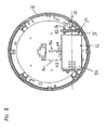
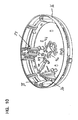
Figure 1 is a view of a base of a smoke alarm that includes a pivoting battery carrier according to the invention, as the smoke alarm would appear to someone looking upward towards the smoke alarm when the smoke alarm is mounted on a ceiling. -
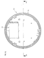
Figure 2 is a view of the smoke alarm housing in the same direction asFigure 1 , with a cover of the alarm housing removed to show details of the interior of the alarm housing. -
Figure 3 is a side view of the battery carrier in a closed position. -
Figure 4 is a side view similar toFigure 3 , showing the battery carrier pushed upward to initiate opening of the carrier. -
Figure 5 is a side view similar toFigure 3 , showing the battery carrier at the open position. -
Figure 6 is a side view similar toFigure 3 , showing the battery carrier being pushed back to the closed position. -
Figure 7 is a side view similar toFigure 3 , showing the battery carrier at the open position with the battery removed to illustrate the lockout mechanism. -
Figure 8 is a side view similar toFigure 3 , showing the battery carrier at the open position with the battery inserted to retract the lockout mechanism. -
Figure 9 is a view similar toFigure 2 but with the battery carrier removed to illustrate the tamper resist mechanism. -
Figure 10 is a perspective view of the alarm housing with the cover removed and with a portion of the tamper resist mechanism removed to illustrate how the tamper resist mechanism is actuated. -
Figure 11A illustrates the tamper resist mechanism relative to the battery carrier, with the tamper resist mechanism at an unlocked position. -
Figure 11B illustrates the tamper resist mechanism at a locked position. -
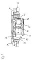
Figure 12 is a view of an alternative embodiment of a smoke alarm employing a battery carrier mounted for linear motion. -
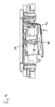
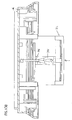
Figure 13A is a cross-sectional view through line 13-13 ofFigure 12 with the battery carrier in a closed position. -
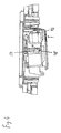
Figure 13B is a cross-sectional view through line 13-13 ofFigure 12 with the battery carrier in an open position. - The invention relates to an electronic device that has a battery carrier into which at least one battery is intended to be placed to wholly or partially power the electronic device. Alternatively, the at least one battery can function as a back-up power source in the event of failure of a primary power source connected to the electronic device. For convenience, the inventive concepts will be described herein with respect to a life safety device, in particular a smoke alarm. However, it is to be realized that the inventive concepts could be applied equally as well to other life safety devices, for example a carbon monoxide alarm or a flame detector, and other electronic devices that utilize at least one battery. In addition, for convenience, the smoke alarm will be described herein as using a single 9-volt battery. However, it is to be realized that the inventive concepts described herein could be utilized with other battery types and sizes, and with more than one battery.
- With reference to
Figure 1 , asmoke alarm 10 having abattery carrier 12 according to the invention is illustrated. Thealarm 10 includes analarm housing 14 which in use will house the smoke detection system and alarm electronics necessary for operation of thealarm 10. The specifics of the smoke detection system and the alarm electronics are not necessary for a proper understanding of the inventive concepts. Suitable smoke detection systems and alarm electronics for use in thealarm 10, as well as the operation of a smoke alarm, would be known to those of skill in the art having read this specification. In the illustrated embodiment, thealarm 10 is preferably powered by mains electrical power, with a 9-volt battery 15 providing back-up power in the event of interruption of mains power. However, the battery could be the primary power source for thealarm 10 if desired. - The
alarm housing 14 includes abase 16 and acover 18 that is connected to thebase 16, as best seen inFigures 1 ,9 and10 . When connected to each other, thebase 16 and thecover 18 enclose the smoke detection system and the alarm electronics. In use, thealarm housing 14 will be detachably connected to a mounting plate 19 that is fixed to, for example, a ceiling in a building in which thealarm 10 is to be used. To achieve connection, thebase 16 includes suitable attachment structure which, in the illustrated embodiment, comprisestabs 20 that are circumferentially spaced around an upper end of thebase 16, as shown inFigures 3-8 . Thetabs 20 engage with suitable structure, such as slots, on the mounting plate 19, with connection being achieved by bringing thealarm housing 14 and mounting plate 19 together and then rotating thealarm housing 14 relative to the mounting plate to effect connection. The use of tabs and slots to detachably connect an alarm housing and a mounting plate upon rotation of the alarm housing relative to the mounting plate is known to those of skill in the art. - Returning to
Figure 1 , thebattery carrier 12 is accessible from the bottom of thealarm housing 14 to permit insertion and replacement of the battery. The terms "upper", "lower", "bottom" and the like, as used herein, are in reference to the smoke alarm in use as it is mounted on a ceiling of a building. Therefore, thebase 16 is generally closer to the ceiling than is thecover 18, and the cover is the portion of the alarm that, in use, will face downward toward the floor of the building. Because thebattery carrier 12 is accessible from the bottom of thealarm housing 14, insertion and replacement of the battery is made easier and can be accomplished without disconnecting the alarm housing from the mounting plate as is required in many conventional smoke alarms. - The
battery carrier 12 will now be described with reference toFigures 2-11 . Thecarrier 12 is a generally rectangular structure withopposed side walls 22, 24 (Figures 11A, 11B ), anupper wall 26 extending between theside walls 22, 24 (Figures 7 ,11A ,11B ), a rear wall 28 (Figure 7 ), abottom wall 30 extending between theside walls 22, 24, and anopen end 31. The walls 22-30 define abattery cavity 32 that is sized to receive thebattery 15 through theopen end 31 thereof with the non-terminal end of the battery toward therear wall 28. - The
rear wall 28 includes apivot shaft 34, the ends of which are rotatably supported byflanges base 16. Thecarrier 12 fits within a rectangular cut-out in thecover 18 and is able to pivot relative to thebase 16 and thecover 18 between a closed position, shown inFigure 3 , and an open position, shown inFigure 5 . In the closed position, thebottom wall 30 is generally flush with the surrounding portions of thecover 18, while in the open position, as shown inFigure 7 , theopen end 31 of thecarrier 12 extends below thecover 18 to permit removal of a battery from and/or insertion of a battery into thecarrier 12. Aspring 33, a portion of which is shown inFigure 2 , engages theupper wall 26 of thecarrier 12 between therear wall 28 and theopen end 31 for biasing thecarrier 12 toward the open position. - A
resilient detent 35, seen inFigures 5 and7 , is connected to thebottom wall 30 for retaining thebattery 15 in thecarrier 12. Thedetent 35 comprises a cantilevered arm connected at oneend 37 to thebottom wall 30 and having an opposite, free end 39 having a raised lip. The lip includes anangled surface 40 which, as will be discussed further below, will initiate downward deflection of the free end 39 during removal of the battery. As shown inFigure 5 , when thebattery 15 is installed, the lip on the end 39 prevents thebattery 15 from falling out of thecarrier 12 when thecarrier 12 pivots to the open position. Removal of thebattery 15 is accomplished by lifting the terminal end of the battery upward and pulling the battery out. When the battery is lifted upward, it engages theangled surface 40 thereby deflecting the free end 39 downward to permit the battery to be pulled out of thecarrier 12. - The
carrier 12 employs a double acting latch mechanism to control the pivoting movements of thecarrier 12 between the open and closed positions, and to retain the carrier at the closed position against the biasing force of thespring 33. The latch mechanism is constructed so that, starting from the closed position (Figure 3 ), movement of thecarrier 12 to the open position is initiated by pushing upward on theend 42 of the carrier (Figure 4 ) and then releasing. This releases the latch mechanism and permits thecarrier 12 to pivot to the open position (Figure 5 ) under the biasing force of thespring 33. To close the carrier, the user again pushes upward on the end 42 (Figure 6 ) until a click is heard, and then releasing. The click indicates that the latch mechanism has engaged to retain the carrier at the closed position. - In the illustrated embodiment, the latch mechanism comprises a heart-shaped
cam groove 44 defined on the outer facing surface of eachside wall 22, 24 of thecarrier 12, andcam follower arms 46 that have ends that ride in the path of thecam groove 44. Only thecam groove 44 in theside wall 22 is visible in the figures. It is to be understood that the cam groove in the side wall 24 is identical in construction to the cam groove shown. Although the use of two cam grooves is described, a single cam groove could be used if desired. - Each
cam groove 44 includes alatch position 48 at which the ends of thefollower arms 46 reside when thecarrier 12 is at the closed position, as shown inFigure 3 . At this position, the carrier is latched closed until the ends of the follower arms are removed from the latch position. Eachcam groove 44 also includes anopen position 50 at which the ends of thefollower arms 46 reside when thecarrier 12 is at the open position, as shown inFigure 5 . At this position, the carrier is held in the open position through the force of thespring 33, with the contact between the follower arms and the cam groove preventing further opening of the carrier. - As shown in
Figures 11A ,11B , thefollower arms 46 are part of an integral,U-shaped structure 52 that extends beneath thecarrier 12 and is pivotally connected to the base 16 to permit thestructure 52 with thefollower arms 46 to pivot as the ends of the follower arms follow the cam path, as shown inFigures 3-6 . Thefollower arms 46 are preferably made of a flexible material so that the ends thereof remain in contact with thecam grooves 44 at all times as the follower arms travel over the steps in the cam path. - The construction and operation of heart-shaped cam grooves is well known, and further details are not described herein. See, for example,
U.S. Patent 5,004,276 . However, the operation will be briefly discussed with reference toFigures 3-6 . From the closed position of thecarrier 12 shown inFigure 3 , where the ends of the follower arms are at thelatch position 48, theend 42 of the carrier is pushed upward as shown inFigure 4 . This causes the ends of the follower arms to leave thelatch position 48 and initiate clockwise travel of the follower arms in thecam groove 44. When the pushing force is released, thecarrier 12 pivots open as shown inFigure 5 , with the follower arms traveling clockwise in thecam groove 44 to the open position. To close the carrier, theend 42 is again pushed upward as shown inFigure 6 , with the follower arms traveling clockwise on the opposite side of the cam groove. Theend 42 is pushed upward until a click is heard, which indicates that the ends of the follower arms have returned to thelatch position 48 to latch the carrier in the closed position. - Therefore, the
carrier 12 with the double acting latch mechanism is intuitive to use, with the user simply pushing upward to open (i.e. push to open), and pushing upward again to close (i.e. push to close). - Turning to
Figures 9 and10 , thealarm 10 is also constructed to prevent closure of thecarrier 12 if thebattery 15 is incorrectly installed in thecarrier 12. Abattery terminal support 54 is connected to the base 16 adjacent theopen end 31 of thecarrier 12. Terminals 56a, 56b for engagement with the negative and positive terminals, respectively, on thebattery 15 to connect the battery with the alarm electronics are mounted on thesupport 54. A first pair of spaced walls 58a, 58b are provided on thesupport 54 between which is the terminal 56a, and a second pair of spaced walls 60a, 60b are provided on thesupport 54 between which is the terminal 56b. - The distance between the walls 58a, 58b is such as to permit the negative terminal on the battery to fit therebetween to engage with the terminal 56a. Likewise, the distance between the walls 60a, 60b is such as to permit the positive terminal on the battery to fit therebetween to engage with the terminal 56b. However, the distance between the walls 60a, 60b is less than the maximum diameter of the negative battery terminal. As a result, the negative battery terminal cannot fit between the walls 60a, 60b.
- Therefore, the battery is properly inserted into the
carrier 12 with the negative battery terminal to the left of the positive battery terminal (when viewingFigure 9 ), so that the negative battery engages the terminal 56a and the positive battery terminal engages the terminal 56b. If the battery is incorrectly inserted into thecarrier 12 with the negative battery terminal to the right of the positive battery terminal (when viewingFigure 9 ), closure of thecarrier 12 is prevented due to interference between the negative battery terminal and the walls 60a, 60b. - An additional feature of the invention is that when the
carrier 12 pivots open, the terminals 56a, 56b are not readily exposed to a user trying to replace the battery. Some smoke alarms use switches to connect and disconnect the terminals when the battery is changed, due to the fact that there could be 120V on the terminals in some instances. However, switches are problematic and inherently unreliable. Thecarrier 12, when it pivots open and the battery is removed, obstructs the path to the terminals 56a, 56b. Therefore, the need to switch the terminals 56a, 56b on and off when the battery is changed is eliminated. - The
alarm 10 also includes a lockout mechanism that prevents closure of thecarrier 12 without the battery installed in the carrier. The provision of a lockout mechanism is important in smoke alarms and other life safety devices, because these devices often do not function properly without the appropriate battery installed. Further, the open carrier provides a visual indication to the user of the alarm that the battery is not installed and the device may not be functioning properly. - Referring to
Figures 7 and8 , the lockout mechanism comprises alockout plate 70 that is slidably mounted along the top surface of theupper wall 26 of thecarrier 12. Theplate 70 is biased to a position in which the front end thereof projects beyond the front edge of theupper wall 26, as shown inFigure 7 , by acoil spring 72. One end of thespring 72 is fixed to theplate 70, and the opposite end of the spring is connected to aprotrusion 74 that is fixed to and extends upward from theupper wall 26. Theplate 70 also includes a raisedarcuate portion 76 that at least partially houses thespring 72, and the rear end of the plate includes atab 78 integral therewith that projects downwardly into the rear of thebattery cavity 32. - In operation of the lockout mechanism, when no battery is present, the
plate 70, including thetab 78 integral therewith, are biased forwardly by thespring 72 as shown inFigure 7 . At this position, the front end of theplate 70 projects past the front edge of theupper wall 26. As a result, when the user tries to close thecarrier 12, the front end of theplate 70 engages the walls 58a, 58b, 60a, and 60b of thesupport 54 thereby preventing closure of thecarrier 12. Thus, the walls of thesupport 54 act as a mechanical stop to prevent closure of the carrier. When a battery is installed into the battery cavity as shown inFigure 8 , the rear or non-terminal end of the battery forces thetab 78 and theplate 70 backward against the bias force of thespring 72. This retracts theplate 70 so that the front end thereof no longer projects beyond the front edge of theupper wall 26, and thecarrier 12 can be pivoted closed without interference from the walls 58a, 58b, 60a, and 60b of thesupport 54. - The biasing force of the
spring 72 acting on the rear of the battery via thetab 74 also biases the battery toward thesupport 54 to provide reliable contact force between the battery terminals and the terminals 56a, 56b when thecarrier 12 is closed. - Turning to
Figures 9-11 , thealarm 10 also includes a tamper resist mechanism to prevent thecarrier 12 from being opened. This prevents tampering with, and unauthorized removal of, the battery from thealarm 10. As previously described herein, thecarrier 12 employs a latch mechanism that includes heart-shaped cam grooves on the carrier and cam followers traveling in the cam grooves. One way to prevent opening of thecarrier 12 employing such a latch mechanism is to prevent initiation of the opening movement of the carrier by preventing the carrier from being pushed upward to release the cam followers from thelatch position 48. - With reference to
Figure 9 , the tamper resist mechanism includes aslide 90 that is slidably disposed on the downward facing surface of thebase 16. Theslide 90 includes a pair of resilient fingers 92a, 92b, each of which includes aprotuberance 94a, 94b at the free end thereof. A pair ofrails 96a, 96b are fixed to the downward facing surface of thebase 16. Therails 96a, 96b face each other and each rail includes a pair of spacednotches 98 that are adapted to receive theprotuberances 94a, 94b. - The
slide 90 is constructed to slide back and forth relative to thebase 16 within the limit of thenotches 98. InFigure 9 , theslide 90 is shown at a "locked" position, with theprotuberances 94a, 94b disposed within a first set of thenotches 98. The shape of theprotuberances 94a, 94b andnotches 98 are such as to permit theslide 90 to be actuated to the left, as shown by the arrow inFigure 9 , by applying a sufficient force to the slide to force theprotuberances 94a, 94b from the first set of notches until theprotuberances 94a, 94b engage with the second set ofnotches 98. At this position, theslide 90 is at an "unlocked" position.Guides slide 90 as it moves between the "locked" and "unlocked" positions. The ends of therails 96a, 96b are preferably configured to prevent overtravel of theslide 90 beyond the "locked" position and beyond the "unlocked" position. - The
slide 90 also includes ablock 104 that is integral therewith. In addition, thecarrier 12 includes ablock 106 that is connected to and projects upwardly from theupper wall 26. As illustrated inFigure 11A , at the "unlocked" position of theslide 90, theblock 104 is retracted to the right (when viewingFigure 11A ), and thecarrier 12 can be pushed upward to initiate opening of the carrier. However, as illustrated inFigure 11B , when theslide 90 is at the "locked" position ofFigure 9 , theblock 104 is disposed above thecarrier 12 immediately above theblock 106. As a result, thecarrier 12 cannot be pushed upward due to engagement between theblocks block 104 is retracted by sliding theslide 90 to the "unlocked" position. - Actuation of the
slide 90 is achieved by using an object, such as the end of a pen or a screwdriver, to move theslide 90. With reference toFigure 10 , theslide 90 has been removed to show aslot 108 that is formed through thebase 16. To access theslot 108, thealarm housing 14 is first detached from the mounting plate 19. The end of the object is then inserted through theslot 108 from the side of the base 16 opposite to that shown inFigure 10 to engage the top side of theslide 90. The object can then be used to actuate the slide between the "locked" and "unlocked" positions. The top side of theslide 90 preferably includes a notch or slot into which the end of the object can be inserted to facilitate actuation of the slide by the object. - With this tamper resist mechanism, there are no loose parts that can be lost, as with many conventional tamper resist mechanisms. Further, the tamper resist mechanism is internal to the
alarm housing 14, which makes it difficult to tamper with or damage the mechanism parts. - The concepts disclosed herein can also be utilized on a battery carrier that is mounted for linear motion. In such a case, the battery carrier would be accessible from the bottom of the alarm housing and would be mounted for linear movement between a first, closed position within the alarm housing and a second, open position extending below the cover to permit removal of a battery and/or insertion of a battery into the carrier. In this embodiment, the heart-shaped cam groove(s) would be arranged such that the axis thereof (i.e. a straight line connecting the latch position and the open position of the cam groove) would be parallel to the direction of linear movement of the carrier. To open the carrier, the user would push upward on the carrier, which would cause the carrier to extend beneath the alarm housing. To close the carrier, the user would again push upward on the carrier until a click is heard, to return the carrier to the closed position. As a result, like the pivoting
carrier 12, the linearly mounted carrier would be a push-to-open and push-to-close arrangement. - An example of a
battery carrier 112 that is mounted for linear motion relative to analarm housing 114 is illustrated inFigures 12 ,13A and13B . Thehousing 114 is shown with itsbase 116. As shown inFigure 13A , where thecarrier 112 is in its closed position, pushing upward on thecarrier 112 in the direction of the arrow initiates opening.Figure 13B illustrates thecarrier 112 in its open position, and by pushing upward in the direction of the arrow, closing of thecarrier 112 is initiated. A pair of cam grooves 144 (only one cam groove is visible in the figures) are formed centrally on thecarrier 112, andcam follower arms 146 engage with thecam grooves 144. - The embodiments of the inventions disclosed herein have been discussed for the purpose of familiarizing the reader with novel aspects of the invention.
Claims (11)
- A life safety alarm, comprising: an alarm housing that houses a system to detect a life threatening condition and alarm electronics; and a battery carrier configured to carry at least one battery, the battery carrier is connected to the alarm housing by a push-to-open and push-to-close mechanism, and where the battery carrier is connected to the alarm housing so as to be moveable relative to the alarm housing between a closed position and an open position.
- The life safety alarm of claim 1, wherein the push-to-open and push- to-close mechanism comprises a double acting latch mechanism connecting the battery carrier to the alarm housing.
- The life safety alarm of claim 1, wherein the push-to-open and push-to-close mechanism is a latch mechanism which includes at least one heart-shaped cam groove and at least one cam follower engaged in the cam groove to control the movements of the battery carrier between the open and closed positions, and to retain the battery carrier at the closed position.
- The life safety alarm of claim 3, wherein the battery carrier is pivotally connected to the housing for pivoting movement relative to the housing between the closed position and the open position.
- The life safety alarm of any one of the preceding claims, wherein the detection system comprises smoke detection system.
- The life safety alarm of claim 3, wherein the heart shaped cam groove is defined on the battery carrier and the cam follower is attached to the housing.
- The life safety alarm of any one of the preceding claims, comprising a spring engaged with the battery carrier that biases the battery carrier toward the open position.
- The life safety alarm of any one of the preceding claims, further comprising structure connected to the housing that is configured to prevent closure of the battery carrier from the open position if a battery is incorrectly installed in the battery carrier.
- The life safety alarm of any one of the preceding claims, further comprising lockout mechanism that is configured to prevent closure of the battery carrier, when the battery carrier is at the open position, without a battery installed in the battery carrier.
- The life safety alarm of any one of the preceding claims, further comprising a tamper resist mechanism that is configured to prevent the battery carrier from being opened when the battery carrier is at the closed position.
- The life safety alarm of any one of the preceding claims, wherein the battery carrier is mounted adjacent on the alarm housing so that it is accessible from the bottom of the alarm housing.
Applications Claiming Priority (5)
| Application Number | Priority Date | Filing Date | Title |
|---|---|---|---|
| US788764 | 1985-10-18 | ||
| US45331903P | 2003-03-10 | 2003-03-10 | |
| US453319P | 2003-03-10 | ||
| US10/788,764 US7492273B2 (en) | 2003-03-10 | 2004-02-27 | Pivoting battery carrier and a life safety device incorporating the same |
| PCT/US2004/006519 WO2004082042A2 (en) | 2003-03-10 | 2004-03-03 | Pivoting battery carrier and a life safety device incorporating the same |
Publications (2)
| Publication Number | Publication Date |
|---|---|
| EP1604412A2 EP1604412A2 (en) | 2005-12-14 |
| EP1604412B1 true EP1604412B1 (en) | 2010-12-29 |
Family
ID=32994490
Family Applications (1)
| Application Number | Title | Priority Date | Filing Date |
|---|---|---|---|
| EP04716945A Expired - Lifetime EP1604412B1 (en) | 2003-03-10 | 2004-03-03 | Pivoting battery carrier and a life safety device incorporating the same |
Country Status (6)
| Country | Link |
|---|---|
| US (2) | US7492273B2 (en) |
| EP (1) | EP1604412B1 (en) |
| JP (1) | JP4531045B2 (en) |
| AT (1) | ATE493768T1 (en) |
| DE (1) | DE602004030773D1 (en) |
| WO (1) | WO2004082042A2 (en) |
Cited By (1)
| Publication number | Priority date | Publication date | Assignee | Title |
|---|---|---|---|---|
| TWI469424B (en) * | 2013-11-13 | 2015-01-11 | Energy Control Ltd | Battery frame structure for a collection battery |
Families Citing this family (30)
| Publication number | Priority date | Publication date | Assignee | Title |
|---|---|---|---|---|
| GB2420899A (en) * | 2004-12-06 | 2006-06-07 | Peter Frost-Gaskin | Smoke alarm housing |
| GB0706941D0 (en) * | 2007-04-11 | 2007-05-16 | Fireangel Ltd | Fire alarm and like devices |
| US20100073172A1 (en) * | 2008-09-25 | 2010-03-25 | L.I.F.E. Support Technologies, Llc | Dual condition fire/smoke detector with adjustable led cannon |
| USD596974S1 (en) * | 2008-12-18 | 2009-07-28 | Honeywell International Inc. | Sounder base housing |
| US8289176B2 (en) * | 2009-02-13 | 2012-10-16 | Peter Joseph Locke | Recessed detector assembly |
| JP2011134541A (en) * | 2009-12-24 | 2011-07-07 | Nifco Inc | Connection structure |
| JP5617477B2 (en) * | 2010-09-24 | 2014-11-05 | ソニー株式会社 | Battery pack and method for monitoring removal of secondary battery in battery pack |
| FR2973174B1 (en) * | 2011-03-25 | 2013-04-05 | Hager Security | CONTACT FITTING ANTI-MOUNTING HOUSING |
| FR2973173B1 (en) * | 2011-03-25 | 2014-01-17 | Hager Security | BOX WITH STOP AND ANTI-CONTACT ORGAN |
| US20120314344A1 (en) * | 2011-06-10 | 2012-12-13 | Eyston Co., Ltd. | Hazardous condition detector housing with front door battery compartment safety feature |
| US9607787B2 (en) * | 2012-09-21 | 2017-03-28 | Google Inc. | Tactile feedback button for a hazard detector and fabrication method thereof |
| CN105164360B (en) * | 2013-04-15 | 2017-04-26 | 卢特龙电子公司 | Motorized window treatment with integrated accessible battery compartment |
| WO2015009350A1 (en) | 2013-07-16 | 2015-01-22 | Leeo, Inc. | Electronic device with environmental monitoring |
| US9116137B1 (en) | 2014-07-15 | 2015-08-25 | Leeo, Inc. | Selective electrical coupling based on environmental conditions |
| DE102014105725A1 (en) * | 2014-04-23 | 2015-10-29 | Wago Verwaltungsgesellschaft Mbh | Electrical device and conductor connection terminal and base part for this purpose |
| US9372477B2 (en) | 2014-07-15 | 2016-06-21 | Leeo, Inc. | Selective electrical coupling based on environmental conditions |
| US9213327B1 (en) | 2014-07-15 | 2015-12-15 | Leeo, Inc. | Selective electrical coupling based on environmental conditions |
| US9170625B1 (en) | 2014-07-15 | 2015-10-27 | Leeo, Inc. | Selective electrical coupling based on environmental conditions |
| US9092060B1 (en) | 2014-08-27 | 2015-07-28 | Leeo, Inc. | Intuitive thermal user interface |
| US10078865B2 (en) | 2014-09-08 | 2018-09-18 | Leeo, Inc. | Sensor-data sub-contracting during environmental monitoring |
| US9445451B2 (en) | 2014-10-20 | 2016-09-13 | Leeo, Inc. | Communicating arbitrary attributes using a predefined characteristic |
| US10026304B2 (en) | 2014-10-20 | 2018-07-17 | Leeo, Inc. | Calibrating an environmental monitoring device |
| US10871349B2 (en) | 2015-01-05 | 2020-12-22 | Crosman Corporation | Firearm associated electronic device with acceleration resistant latch |
| US9801013B2 (en) | 2015-11-06 | 2017-10-24 | Leeo, Inc. | Electronic-device association based on location duration |
| US10805775B2 (en) | 2015-11-06 | 2020-10-13 | Jon Castor | Electronic-device detection and activity association |
| FR3044472B1 (en) * | 2015-11-27 | 2017-12-15 | Ingenico Group | REMOVABLE CLOSURE CAP FOR A LOCATION SUITABLE FOR RECEIVING AT LEAST ONE BATTERY OF AN ELECTRONIC DEVICE AND CORRESPONDING ELECTRONIC DEVICE. |
| WO2018183645A1 (en) * | 2017-03-29 | 2018-10-04 | Milwaukee Electric Tool Corporation | Battery charger |
| US11252828B2 (en) * | 2019-09-05 | 2022-02-15 | Geoffrey M. Hopkins | Housing and wall mount casing for google nest guard or similar article |
| CN111009095B (en) * | 2019-12-25 | 2021-11-09 | 红米塑业科技(台州)有限公司 | Smoke detector bottom shell with side-moving battery groove body |
| US11676476B2 (en) * | 2021-05-14 | 2023-06-13 | SimpliSafe, Inc. | Battery tamper indicator for detector |
Family Cites Families (83)
| Publication number | Priority date | Publication date | Assignee | Title |
|---|---|---|---|---|
| CA840598A (en) | 1970-04-28 | A. Sidell Philip | Battery ejector for portable appliances | |
| CA866362A (en) | 1971-03-16 | Simon Horst | Cell holder | |
| CA753712A (en) | 1967-02-28 | C. Davis Charles | Pushbutton latching and locking attachment | |
| CA797353A (en) | 1968-10-22 | E. Johnson James | Electric control device | |
| CA505307A (en) | 1954-08-24 | F. E. Goos Carlos | Retaining device | |
| CA452797A (en) | 1948-11-23 | American Can Company | Cam mechanism | |
| US3156493A (en) | 1960-10-21 | 1964-11-10 | Camloc Fastener Corp | Push button fastener |
| US3697714A (en) | 1971-07-28 | 1972-10-10 | Ite Imperial Corp | Rotary handle operator with reversible cover latch |
| US3979228A (en) | 1975-05-01 | 1976-09-07 | Sperry Rand Corporation | Battery operated appliance |
| US4075561A (en) | 1976-11-01 | 1978-02-21 | General Electric Company | Programmable electrical apparatus containing a battery |
| JPS5811016Y2 (en) | 1977-05-13 | 1983-03-01 | オリンパス光学工業株式会社 | Battery box removal device |
| NL7714233A (en) | 1977-12-22 | 1979-06-26 | Philips Nv | BATTERY HOLDER. |
| DE3065743D1 (en) | 1979-03-02 | 1984-01-05 | Philips Electronic Associated | Cam and follower arrangement, and monochromator of a spectrophotometer including such an arrangement |
| US4228428A (en) | 1979-04-02 | 1980-10-14 | Niedermeyer Karl O | Visible signal for alarm, such as a smoke detector |
| US4297635A (en) | 1979-11-19 | 1981-10-27 | General Electric Company | Watthour meter and battery retaining apparatus therefor |
| JPS5756957U (en) | 1980-09-22 | 1982-04-03 | ||
| US4389550A (en) * | 1980-10-09 | 1983-06-21 | Reiter John J | Switch actuating mechanism |
| US4391883A (en) | 1981-09-28 | 1983-07-05 | Motorola, Inc. | Housing arrangement with breakaway battery access door |
| US4405844A (en) | 1982-04-01 | 1983-09-20 | S&C Electric Company | Door interlock for electrical apparatus |
| CA1188773A (en) | 1983-02-23 | 1985-06-11 | Laurent Cormier | Smoke detector indicator |
| US4625259A (en) * | 1984-04-12 | 1986-11-25 | Prentice Corporation | Integral pivoting power supply |
| US4777559A (en) | 1984-10-24 | 1988-10-11 | S&C Electric Company | Article mounting and handling method and apparatus |
| DE3700453A1 (en) | 1986-01-15 | 1987-07-23 | Schadow Rudolf Gmbh | Push-button or slide-key switch |
| JPH0426946Y2 (en) | 1986-02-13 | 1992-06-29 | ||
| DE3641684A1 (en) | 1986-12-06 | 1988-06-16 | Schadow Rudolf Gmbh | Push-button unit |
| US4711511A (en) | 1987-01-23 | 1987-12-08 | Thomas & Betts Corporation | Latching apparatus for an electrical connector |
| CH675792A5 (en) * | 1988-02-04 | 1990-10-31 | Olten Ag Elektro Apparatebau | |
| US4870395A (en) | 1988-03-10 | 1989-09-26 | Seatt Corporation | Battery powered smoke alarm safety lockout system |
| JP2808284B2 (en) * | 1988-08-23 | 1998-10-08 | 旭光学工業株式会社 | Battery lid opening and closing device |
| SE461989B (en) | 1988-09-16 | 1990-04-23 | Electrolux Ab | LOADING MACHINE FOR A CLOSER TO A WASHER, CENTRIFUG |
| US4904549A (en) | 1988-11-04 | 1990-02-27 | Motorola, Inc. | Battery housing with integral latch and positive displacement apparatus |
| US4885219A (en) | 1988-11-21 | 1989-12-05 | American Telephone And Telegraph Company | Rotatable storage compartment for batteries and the like |
| US4881063A (en) | 1989-01-30 | 1989-11-14 | Ei Company, Ltd. | Battery removal indicator |
| US4959640A (en) | 1989-03-09 | 1990-09-25 | Pioneer Manufacturing, Inc. | Apparatus for detect missing battery in smoke detector |
| US5055830A (en) | 1989-06-12 | 1991-10-08 | Pittway Corporation | Battery sensing mechanism |
| US5103216A (en) * | 1989-06-12 | 1992-04-07 | Pittway Corporation | Improperly inserted battery detector |
| US5050922A (en) | 1989-11-30 | 1991-09-24 | United Technologies Automotive | Overhead console having a pivotable storage shelf-door |
| US5004276A (en) | 1990-01-22 | 1991-04-02 | The Stanley Works | Push to close latch for self-cleaning oven |
| US5053752A (en) | 1990-02-26 | 1991-10-01 | Jack Epstein | Smoke detector and method using elongated flexible low battery condition indicator member |
| US5191855A (en) * | 1990-02-26 | 1993-03-09 | Pittway Corporation | Battery missing indicator |
| JPH0441880A (en) | 1990-06-07 | 1992-02-12 | Inoue Kanamono Kk | Push latch device |
| JP2912433B2 (en) | 1990-09-04 | 1999-06-28 | 株式会社ニフコ | In-vehicle latch device |
| US5072974A (en) * | 1991-02-07 | 1991-12-17 | The Stanley Works | Push to close latch for self-cleaning oven |
| US5412542A (en) * | 1991-03-20 | 1995-05-02 | Man-D-Tec, Inc. | Down lighting systems and fixtures therefor |
| CA2056534A1 (en) | 1991-11-28 | 1993-05-29 | Peter A. Massacesi | Retractable battery tray |
| CA2060131C (en) | 1992-01-28 | 1995-06-27 | John Mallory | Battery socket for smoke detector |
| US5213913A (en) | 1992-02-21 | 1993-05-25 | Snap-On Tools Corporation | Latching arrangement for battery pack |
| JP3188983B2 (en) | 1992-04-25 | 2001-07-16 | 能美防災株式会社 | Sensor base |
| US5444434A (en) * | 1992-06-15 | 1995-08-22 | Serby; Victor M. | Extended life smoke detector |
| US5337215A (en) * | 1992-07-10 | 1994-08-09 | Sherwood Medical Company | Pivoting battery compartment and door |
| JPH0738505B2 (en) | 1992-10-12 | 1995-04-26 | インターナショナル・ビジネス・マシーンズ・コーポレイション | Structure with lid and information processing device |
| CH685409A5 (en) | 1993-03-19 | 1995-06-30 | Cerberus Ag | Fire alarm. |
| US5314763A (en) | 1993-07-20 | 1994-05-24 | Motorola, Inc. | Battery latch |
| US5476729A (en) | 1993-08-18 | 1995-12-19 | Invisible Fence Company, Inc. | Electronic device having a removable battery pack assembly |
| US5413499A (en) * | 1993-10-12 | 1995-05-09 | Amprobe Instrument | Battery holder |
| US5363976A (en) * | 1994-03-01 | 1994-11-15 | Kapka John J | Smoke detector security cover |
| US5498039A (en) * | 1994-04-20 | 1996-03-12 | Illinois Tool Works Inc. | Spring loaded latch assembly |
| US5508124A (en) * | 1994-08-23 | 1996-04-16 | Motorola, Inc. | Confined battery door |
| US5652569A (en) * | 1994-09-02 | 1997-07-29 | Paul Joseph Gerstenberger | Child alarm |
| US5578996A (en) | 1994-11-23 | 1996-11-26 | Brk Brands, Inc. | Long life detector |
| US5646598A (en) * | 1995-05-02 | 1997-07-08 | Nickles; Aaron Michael | Smoke detector with advanced safety features |
| US5733673A (en) | 1995-06-07 | 1998-03-31 | Norand Corporation | Method and apparatus to detect imminent battery removal in a portable electronic device |
| CA2190572A1 (en) | 1995-11-24 | 1997-05-25 | Wille Kottke | Battery latch for a communication device |
| US5607792A (en) | 1996-02-05 | 1997-03-04 | Motorola, Inc. | Battery latch |
| US5617079A (en) * | 1996-03-12 | 1997-04-01 | Harrison; Frank | Apparatus for replacing a battery in a battery powered device |
| JP3405633B2 (en) * | 1996-03-19 | 2003-05-12 | 富士通株式会社 | Portable device and battery lock mechanism |
| JPH09297631A (en) | 1996-04-30 | 1997-11-18 | Toshiba Corp | Portable equipment |
| US5820406A (en) * | 1996-07-29 | 1998-10-13 | Hetherington; Michael Warnett | Terminal and door latch for battery operated devices |
| US6117575A (en) * | 1997-02-12 | 2000-09-12 | Amei Technologies, Inc. | Battery compartment |
| US5786759A (en) * | 1997-05-15 | 1998-07-28 | Ling; Chong-Kuan | Alarming wire lock |
| JP2887865B2 (en) | 1997-06-02 | 1999-05-10 | アルプス電気株式会社 | Connector device |
| US6265091B1 (en) | 1997-06-06 | 2001-07-24 | Johnson Controls Technology Company | Modular electric storage battery |
| US5995363A (en) * | 1998-03-05 | 1999-11-30 | Wu; Wen-Kao | Structure of a carrying case for computer peripherals |
| DE29814433U1 (en) * | 1998-08-11 | 1999-03-04 | Microlife Investments Corp., Shihlin, Taipeh | Battery operated device, in particular a blood pressure meter |
| US6294286B1 (en) | 1998-12-07 | 2001-09-25 | Eleven Engineering Inc. | Quick change battery retainer |
| DE29912015U1 (en) * | 1999-07-09 | 1999-09-16 | Chang, Chien-Kuo, Taichung | Worktable |
| US6160487A (en) * | 1999-07-22 | 2000-12-12 | Kidde Walter Portable Equipment Inc | Single lockout mechanism for a multiple battery compartment that is particularly suited for smoke and carbon monoxide detector apparatus |
| JP3070330U (en) * | 2000-01-17 | 2000-07-28 | 船井電機株式会社 | Battery storage device |
| AU2001271846A1 (en) * | 2000-07-03 | 2002-01-30 | Stoneridge Control Devices, Inc. | Fuel door lock actuator |
| US6464437B1 (en) * | 2000-10-26 | 2002-10-15 | Putco, Inc. | Push-down pop-up tie mechanism |
| US6511770B2 (en) * | 2000-12-14 | 2003-01-28 | Kang-Chao Chang | Battery casing with an ejector |
| US6943691B2 (en) * | 2001-01-19 | 2005-09-13 | Bill Chambers | Tamper indicator for a smoke detector |
| US6572392B2 (en) * | 2001-06-19 | 2003-06-03 | Japan Aviation Electronics Industry, Limited | Push-push type card connector comprising a cam mechanism using a generally heart-shaped cam groove |
-
2004
- 2004-02-27 US US10/788,764 patent/US7492273B2/en active Active
- 2004-03-03 WO PCT/US2004/006519 patent/WO2004082042A2/en not_active Ceased
- 2004-03-03 AT AT04716945T patent/ATE493768T1/en not_active IP Right Cessation
- 2004-03-03 EP EP04716945A patent/EP1604412B1/en not_active Expired - Lifetime
- 2004-03-03 DE DE602004030773T patent/DE602004030773D1/en not_active Expired - Lifetime
- 2004-03-03 JP JP2006509053A patent/JP4531045B2/en not_active Expired - Fee Related
-
2008
- 2008-08-29 US US12/201,348 patent/US7948389B2/en not_active Expired - Lifetime
Cited By (1)
| Publication number | Priority date | Publication date | Assignee | Title |
|---|---|---|---|---|
| TWI469424B (en) * | 2013-11-13 | 2015-01-11 | Energy Control Ltd | Battery frame structure for a collection battery |
Also Published As
| Publication number | Publication date |
|---|---|
| DE602004030773D1 (en) | 2011-02-10 |
| US20080316044A1 (en) | 2008-12-25 |
| US20040229113A1 (en) | 2004-11-18 |
| JP2006526839A (en) | 2006-11-24 |
| WO2004082042A2 (en) | 2004-09-23 |
| EP1604412A2 (en) | 2005-12-14 |
| JP4531045B2 (en) | 2010-08-25 |
| US7948389B2 (en) | 2011-05-24 |
| US7492273B2 (en) | 2009-02-17 |
| WO2004082042A3 (en) | 2006-07-06 |
| ATE493768T1 (en) | 2011-01-15 |
Similar Documents
| Publication | Publication Date | Title |
|---|---|---|
| EP1604412B1 (en) | Pivoting battery carrier and a life safety device incorporating the same | |
| US6160487A (en) | Single lockout mechanism for a multiple battery compartment that is particularly suited for smoke and carbon monoxide detector apparatus | |
| CA2034437C (en) | Circuit breaker handle interlock arrangement | |
| US5103216A (en) | Improperly inserted battery detector | |
| JPS6019879Y2 (en) | Storage with drawers | |
| US20120314344A1 (en) | Hazardous condition detector housing with front door battery compartment safety feature | |
| JPS62141906A (en) | switchgear cubicle | |
| JP5351822B2 (en) | Sliding door device with electric lock | |
| CN212425042U (en) | An elevator door locking hook | |
| CN212562834U (en) | Lockset device and opening and closing cabinet | |
| US4706065A (en) | Pull station | |
| CN215108265U (en) | Automatic limiting unit of electric door closer | |
| JP2006079839A (en) | Drawer type opening / closing device interlock device | |
| JP3845481B2 (en) | The mechanism of dead bolts for sliding door electric locks. | |
| CN113107300A (en) | Automatic limiting unit of electric door closer | |
| JP3516237B2 (en) | Door guard | |
| CN219320855U (en) | Monitoring device of monitored equipment of monitoring station | |
| JP3909895B2 (en) | Electric lock for sliding door | |
| CN224048888U (en) | Smart keys and smart locks for manhole covers | |
| CN214429011U (en) | High-voltage distribution box with monitoring and alarming functions | |
| CN224190826U (en) | Panel component of switch and switch | |
| CN223638283U (en) | Locking mechanism for linkage of explosion-proof switch and switch cabinet | |
| CN219081281U (en) | Mechanism lock on automatic reclosing controller | |
| CN223927249U (en) | A mechanical interlocking device for an inflatable high-voltage switchgear | |
| JP3860865B2 (en) | Control device for locking / unlocking of electric lock for sliding door |
Legal Events
| Date | Code | Title | Description |
|---|---|---|---|
| PUAI | Public reference made under article 153(3) epc to a published international application that has entered the european phase |
Free format text: ORIGINAL CODE: 0009012 |
|
| 17P | Request for examination filed |
Effective date: 20050906 |
|
| AK | Designated contracting states |
Kind code of ref document: A2 Designated state(s): AT BE BG CH CY CZ DE DK EE ES FI FR GB GR HU IE IT LI LU MC NL PL PT RO SE SI SK TR |
|
| AX | Request for extension of the european patent |
Extension state: AL LT LV MK |
|
| DAX | Request for extension of the european patent (deleted) | ||
| PUAK | Availability of information related to the publication of the international search report |
Free format text: ORIGINAL CODE: 0009015 |
|
| 17Q | First examination report despatched |
Effective date: 20061123 |
|
| GRAP | Despatch of communication of intention to grant a patent |
Free format text: ORIGINAL CODE: EPIDOSNIGR1 |
|
| GRAS | Grant fee paid |
Free format text: ORIGINAL CODE: EPIDOSNIGR3 |
|
| GRAA | (expected) grant |
Free format text: ORIGINAL CODE: 0009210 |
|
| AK | Designated contracting states |
Kind code of ref document: B1 Designated state(s): AT BE BG CH CY CZ DE DK EE ES FI FR GB GR HU IE IT LI LU MC NL PL PT RO SE SI SK TR |
|
| REG | Reference to a national code |
Ref country code: GB Ref legal event code: FG4D |
|
| REG | Reference to a national code |
Ref country code: CH Ref legal event code: EP |
|
| REG | Reference to a national code |
Ref country code: IE Ref legal event code: FG4D |
|
| REF | Corresponds to: |
Ref document number: 602004030773 Country of ref document: DE Date of ref document: 20110210 Kind code of ref document: P |
|
| REG | Reference to a national code |
Ref country code: DE Ref legal event code: R096 Ref document number: 602004030773 Country of ref document: DE Effective date: 20110210 |
|
| REG | Reference to a national code |
Ref country code: NL Ref legal event code: T3 |
|
| PG25 | Lapsed in a contracting state [announced via postgrant information from national office to epo] |
Ref country code: SI Free format text: LAPSE BECAUSE OF FAILURE TO SUBMIT A TRANSLATION OF THE DESCRIPTION OR TO PAY THE FEE WITHIN THE PRESCRIBED TIME-LIMIT Effective date: 20101229 Ref country code: BG Free format text: LAPSE BECAUSE OF FAILURE TO SUBMIT A TRANSLATION OF THE DESCRIPTION OR TO PAY THE FEE WITHIN THE PRESCRIBED TIME-LIMIT Effective date: 20110329 Ref country code: SE Free format text: LAPSE BECAUSE OF FAILURE TO SUBMIT A TRANSLATION OF THE DESCRIPTION OR TO PAY THE FEE WITHIN THE PRESCRIBED TIME-LIMIT Effective date: 20101229 Ref country code: CY Free format text: LAPSE BECAUSE OF FAILURE TO SUBMIT A TRANSLATION OF THE DESCRIPTION OR TO PAY THE FEE WITHIN THE PRESCRIBED TIME-LIMIT Effective date: 20101229 Ref country code: FI Free format text: LAPSE BECAUSE OF FAILURE TO SUBMIT A TRANSLATION OF THE DESCRIPTION OR TO PAY THE FEE WITHIN THE PRESCRIBED TIME-LIMIT Effective date: 20101229 Ref country code: AT Free format text: LAPSE BECAUSE OF FAILURE TO SUBMIT A TRANSLATION OF THE DESCRIPTION OR TO PAY THE FEE WITHIN THE PRESCRIBED TIME-LIMIT Effective date: 20101229 |
|
| PG25 | Lapsed in a contracting state [announced via postgrant information from national office to epo] |
Ref country code: PT Free format text: LAPSE BECAUSE OF FAILURE TO SUBMIT A TRANSLATION OF THE DESCRIPTION OR TO PAY THE FEE WITHIN THE PRESCRIBED TIME-LIMIT Effective date: 20110429 Ref country code: BE Free format text: LAPSE BECAUSE OF FAILURE TO SUBMIT A TRANSLATION OF THE DESCRIPTION OR TO PAY THE FEE WITHIN THE PRESCRIBED TIME-LIMIT Effective date: 20101229 Ref country code: ES Free format text: LAPSE BECAUSE OF FAILURE TO SUBMIT A TRANSLATION OF THE DESCRIPTION OR TO PAY THE FEE WITHIN THE PRESCRIBED TIME-LIMIT Effective date: 20110409 Ref country code: GR Free format text: LAPSE BECAUSE OF FAILURE TO SUBMIT A TRANSLATION OF THE DESCRIPTION OR TO PAY THE FEE WITHIN THE PRESCRIBED TIME-LIMIT Effective date: 20110330 Ref country code: EE Free format text: LAPSE BECAUSE OF FAILURE TO SUBMIT A TRANSLATION OF THE DESCRIPTION OR TO PAY THE FEE WITHIN THE PRESCRIBED TIME-LIMIT Effective date: 20101229 Ref country code: CZ Free format text: LAPSE BECAUSE OF FAILURE TO SUBMIT A TRANSLATION OF THE DESCRIPTION OR TO PAY THE FEE WITHIN THE PRESCRIBED TIME-LIMIT Effective date: 20101229 |
|
| PG25 | Lapsed in a contracting state [announced via postgrant information from national office to epo] |
Ref country code: RO Free format text: LAPSE BECAUSE OF FAILURE TO SUBMIT A TRANSLATION OF THE DESCRIPTION OR TO PAY THE FEE WITHIN THE PRESCRIBED TIME-LIMIT Effective date: 20101229 Ref country code: SK Free format text: LAPSE BECAUSE OF FAILURE TO SUBMIT A TRANSLATION OF THE DESCRIPTION OR TO PAY THE FEE WITHIN THE PRESCRIBED TIME-LIMIT Effective date: 20101229 Ref country code: PL Free format text: LAPSE BECAUSE OF FAILURE TO SUBMIT A TRANSLATION OF THE DESCRIPTION OR TO PAY THE FEE WITHIN THE PRESCRIBED TIME-LIMIT Effective date: 20101229 |
|
| PG25 | Lapsed in a contracting state [announced via postgrant information from national office to epo] |
Ref country code: MC Free format text: LAPSE BECAUSE OF NON-PAYMENT OF DUE FEES Effective date: 20110331 Ref country code: DK Free format text: LAPSE BECAUSE OF FAILURE TO SUBMIT A TRANSLATION OF THE DESCRIPTION OR TO PAY THE FEE WITHIN THE PRESCRIBED TIME-LIMIT Effective date: 20101229 |
|
| REG | Reference to a national code |
Ref country code: CH Ref legal event code: PL |
|
| PLBE | No opposition filed within time limit |
Free format text: ORIGINAL CODE: 0009261 |
|
| STAA | Information on the status of an ep patent application or granted ep patent |
Free format text: STATUS: NO OPPOSITION FILED WITHIN TIME LIMIT |
|
| 26N | No opposition filed |
Effective date: 20110930 |
|
| REG | Reference to a national code |
Ref country code: IE Ref legal event code: MM4A |
|
| REG | Reference to a national code |
Ref country code: DE Ref legal event code: R097 Ref document number: 602004030773 Country of ref document: DE Effective date: 20110930 |
|
| PG25 | Lapsed in a contracting state [announced via postgrant information from national office to epo] |
Ref country code: IE Free format text: LAPSE BECAUSE OF NON-PAYMENT OF DUE FEES Effective date: 20110303 Ref country code: CH Free format text: LAPSE BECAUSE OF NON-PAYMENT OF DUE FEES Effective date: 20110331 Ref country code: LI Free format text: LAPSE BECAUSE OF NON-PAYMENT OF DUE FEES Effective date: 20110331 |
|
| PG25 | Lapsed in a contracting state [announced via postgrant information from national office to epo] |
Ref country code: IT Free format text: LAPSE BECAUSE OF FAILURE TO SUBMIT A TRANSLATION OF THE DESCRIPTION OR TO PAY THE FEE WITHIN THE PRESCRIBED TIME-LIMIT Effective date: 20101229 |
|
| PG25 | Lapsed in a contracting state [announced via postgrant information from national office to epo] |
Ref country code: LU Free format text: LAPSE BECAUSE OF NON-PAYMENT OF DUE FEES Effective date: 20110303 |
|
| PG25 | Lapsed in a contracting state [announced via postgrant information from national office to epo] |
Ref country code: TR Free format text: LAPSE BECAUSE OF FAILURE TO SUBMIT A TRANSLATION OF THE DESCRIPTION OR TO PAY THE FEE WITHIN THE PRESCRIBED TIME-LIMIT Effective date: 20101229 |
|
| PG25 | Lapsed in a contracting state [announced via postgrant information from national office to epo] |
Ref country code: HU Free format text: LAPSE BECAUSE OF FAILURE TO SUBMIT A TRANSLATION OF THE DESCRIPTION OR TO PAY THE FEE WITHIN THE PRESCRIBED TIME-LIMIT Effective date: 20101229 |
|
| PGFP | Annual fee paid to national office [announced via postgrant information from national office to epo] |
Ref country code: FR Payment date: 20140311 Year of fee payment: 11 |
|
| PGFP | Annual fee paid to national office [announced via postgrant information from national office to epo] |
Ref country code: DE Payment date: 20140417 Year of fee payment: 11 |
|
| PGFP | Annual fee paid to national office [announced via postgrant information from national office to epo] |
Ref country code: NL Payment date: 20150309 Year of fee payment: 12 |
|
| REG | Reference to a national code |
Ref country code: DE Ref legal event code: R119 Ref document number: 602004030773 Country of ref document: DE |
|
| REG | Reference to a national code |
Ref country code: FR Ref legal event code: ST Effective date: 20151130 |
|
| PG25 | Lapsed in a contracting state [announced via postgrant information from national office to epo] |
Ref country code: DE Free format text: LAPSE BECAUSE OF NON-PAYMENT OF DUE FEES Effective date: 20151001 |
|
| PG25 | Lapsed in a contracting state [announced via postgrant information from national office to epo] |
Ref country code: FR Free format text: LAPSE BECAUSE OF NON-PAYMENT OF DUE FEES Effective date: 20150331 |
|
| REG | Reference to a national code |
Ref country code: NL Ref legal event code: MM Effective date: 20160401 |
|
| PG25 | Lapsed in a contracting state [announced via postgrant information from national office to epo] |
Ref country code: NL Free format text: LAPSE BECAUSE OF NON-PAYMENT OF DUE FEES Effective date: 20160401 |
|
| PGFP | Annual fee paid to national office [announced via postgrant information from national office to epo] |
Ref country code: GB Payment date: 20220225 Year of fee payment: 19 |
|
| GBPC | Gb: european patent ceased through non-payment of renewal fee |
Effective date: 20230303 |
|
| PG25 | Lapsed in a contracting state [announced via postgrant information from national office to epo] |
Ref country code: GB Free format text: LAPSE BECAUSE OF NON-PAYMENT OF DUE FEES Effective date: 20230303 |
|
| PG25 | Lapsed in a contracting state [announced via postgrant information from national office to epo] |
Ref country code: GB Free format text: LAPSE BECAUSE OF NON-PAYMENT OF DUE FEES Effective date: 20230303 |