EP1603698B1 - Tool and cutting insert for the fine turning of grooves in workpieces - Google Patents
Tool and cutting insert for the fine turning of grooves in workpieces Download PDFInfo
- Publication number
- EP1603698B1 EP1603698B1 EP04718783A EP04718783A EP1603698B1 EP 1603698 B1 EP1603698 B1 EP 1603698B1 EP 04718783 A EP04718783 A EP 04718783A EP 04718783 A EP04718783 A EP 04718783A EP 1603698 B1 EP1603698 B1 EP 1603698B1
- Authority
- EP
- European Patent Office
- Prior art keywords
- cutting insert
- cutting
- edge
- seat
- insert
- Prior art date
- Legal status (The legal status is an assumption and is not a legal conclusion. Google has not performed a legal analysis and makes no representation as to the accuracy of the status listed.)
- Expired - Lifetime
Links
- 238000005520 cutting process Methods 0.000 title claims abstract description 232
- 238000006073 displacement reaction Methods 0.000 claims abstract description 7
- 239000011796 hollow space material Substances 0.000 claims description 20
- 238000005452 bending Methods 0.000 claims description 12
- 230000008878 coupling Effects 0.000 claims description 10
- 238000010168 coupling process Methods 0.000 claims description 10
- 238000005859 coupling reaction Methods 0.000 claims description 10
- 230000007704 transition Effects 0.000 claims description 8
- 239000012809 cooling fluid Substances 0.000 claims description 6
- 230000001154 acute effect Effects 0.000 claims description 3
- 230000013011 mating Effects 0.000 claims 1
- 239000007921 spray Substances 0.000 claims 1
- 230000000087 stabilizing effect Effects 0.000 abstract 1
- 238000003754 machining Methods 0.000 description 13
- 239000000463 material Substances 0.000 description 6
- 230000015572 biosynthetic process Effects 0.000 description 5
- 238000005755 formation reaction Methods 0.000 description 5
- 230000008901 benefit Effects 0.000 description 3
- 238000010276 construction Methods 0.000 description 2
- 230000007547 defect Effects 0.000 description 2
- 238000000034 method Methods 0.000 description 2
- 238000005476 soldering Methods 0.000 description 2
- 238000005507 spraying Methods 0.000 description 2
- 229910000831 Steel Inorganic materials 0.000 description 1
- 239000000969 carrier Substances 0.000 description 1
- 239000000919 ceramic Substances 0.000 description 1
- 239000012530 fluid Substances 0.000 description 1
- 229910052751 metal Inorganic materials 0.000 description 1
- 239000002184 metal Substances 0.000 description 1
- 150000002739 metals Chemical class 0.000 description 1
- 238000012986 modification Methods 0.000 description 1
- 230000004048 modification Effects 0.000 description 1
- 238000005498 polishing Methods 0.000 description 1
- 230000009467 reduction Effects 0.000 description 1
- 230000000717 retained effect Effects 0.000 description 1
- 239000010959 steel Substances 0.000 description 1
Images





Classifications
-
- B—PERFORMING OPERATIONS; TRANSPORTING
- B23—MACHINE TOOLS; METAL-WORKING NOT OTHERWISE PROVIDED FOR
- B23B—TURNING; BORING
- B23B27/00—Tools for turning or boring machines; Tools of a similar kind in general; Accessories therefor
- B23B27/10—Cutting tools with special provision for cooling
-
- B—PERFORMING OPERATIONS; TRANSPORTING
- B23—MACHINE TOOLS; METAL-WORKING NOT OTHERWISE PROVIDED FOR
- B23B—TURNING; BORING
- B23B27/00—Tools for turning or boring machines; Tools of a similar kind in general; Accessories therefor
- B23B27/06—Profile cutting tools, i.e. forming-tools
-
- B—PERFORMING OPERATIONS; TRANSPORTING
- B23—MACHINE TOOLS; METAL-WORKING NOT OTHERWISE PROVIDED FOR
- B23B—TURNING; BORING
- B23B2200/00—Details of cutting inserts
- B23B2200/16—Supporting or bottom surfaces
- B23B2200/161—Supporting or bottom surfaces with projections
-
- B—PERFORMING OPERATIONS; TRANSPORTING
- B23—MACHINE TOOLS; METAL-WORKING NOT OTHERWISE PROVIDED FOR
- B23B—TURNING; BORING
- B23B2205/00—Fixation of cutting inserts in holders
- B23B2205/12—Seats for cutting inserts
-
- B—PERFORMING OPERATIONS; TRANSPORTING
- B23—MACHINE TOOLS; METAL-WORKING NOT OTHERWISE PROVIDED FOR
- B23B—TURNING; BORING
- B23B2220/00—Details of turning, boring or drilling processes
- B23B2220/12—Grooving
-
- Y—GENERAL TAGGING OF NEW TECHNOLOGICAL DEVELOPMENTS; GENERAL TAGGING OF CROSS-SECTIONAL TECHNOLOGIES SPANNING OVER SEVERAL SECTIONS OF THE IPC; TECHNICAL SUBJECTS COVERED BY FORMER USPC CROSS-REFERENCE ART COLLECTIONS [XRACs] AND DIGESTS
- Y10—TECHNICAL SUBJECTS COVERED BY FORMER USPC
- Y10T—TECHNICAL SUBJECTS COVERED BY FORMER US CLASSIFICATION
- Y10T407/00—Cutters, for shaping
- Y10T407/14—Cutters, for shaping with means to apply fluid to cutting tool
-
- Y—GENERAL TAGGING OF NEW TECHNOLOGICAL DEVELOPMENTS; GENERAL TAGGING OF CROSS-SECTIONAL TECHNOLOGIES SPANNING OVER SEVERAL SECTIONS OF THE IPC; TECHNICAL SUBJECTS COVERED BY FORMER USPC CROSS-REFERENCE ART COLLECTIONS [XRACs] AND DIGESTS
- Y10—TECHNICAL SUBJECTS COVERED BY FORMER USPC
- Y10T—TECHNICAL SUBJECTS COVERED BY FORMER US CLASSIFICATION
- Y10T407/00—Cutters, for shaping
- Y10T407/22—Cutters, for shaping including holder having seat for inserted tool
- Y10T407/2272—Cutters, for shaping including holder having seat for inserted tool with separate means to fasten tool to holder
- Y10T407/2274—Apertured tool
-
- Y—GENERAL TAGGING OF NEW TECHNOLOGICAL DEVELOPMENTS; GENERAL TAGGING OF CROSS-SECTIONAL TECHNOLOGIES SPANNING OVER SEVERAL SECTIONS OF THE IPC; TECHNICAL SUBJECTS COVERED BY FORMER USPC CROSS-REFERENCE ART COLLECTIONS [XRACs] AND DIGESTS
- Y10—TECHNICAL SUBJECTS COVERED BY FORMER USPC
- Y10T—TECHNICAL SUBJECTS COVERED BY FORMER US CLASSIFICATION
- Y10T407/00—Cutters, for shaping
- Y10T407/23—Cutters, for shaping including tool having plural alternatively usable cutting edges
Definitions
- this invention relates to a tool for the fine turning of rotationally symmetrical grooves in workpieces
- a tool for the fine turning of rotationally symmetrical grooves in workpieces comprising a basic body and a cutting insert, which is delimited by a top side, a bottom side and at least one clearance surface between the same, and which is possible to fix in a cutting seat on a bracket included in the basic body, which bracket includes a narrow neck part and a support part protruding laterally from the same with the purpose of supporting a portion of the cutting insert protruding laterally in relation to the neck part with the purpose of enabling, in a workpiece, the turning of internal shoulder surfaces of a hollow space countersunk inside a narrow gap of the groove and having a greater width than the gap.
- the invention also relates to a cutting insert for use in the tool according to the invention.
- grooves are at times formed having a generally dovetail-like cross-section shape, which have the purpose of securing or clamping fastening elements to different details protruding from the envelope surface on the product which is to be manufactured.
- Examples of products having such grooves are accounted for in US 5,846,054 , US 6,065,938 and US 6,439,851 .
- the individual fastening element should be possible to insert into the groove in order to secure the detail, e.g. a fan blade, against centrifugal forces, which aim to throw out the detail radially from the product when the same rotates.
- the individual groove includes a relatively narrow gap, which opens in the surface of the product or of the workpiece, as well as a hollow space located deeper in the material, which is wider than the gap.
- Said hollow space is delimited by a bottom surface and two usually concavely curved side surfaces, which transform into limiting surfaces of the gap via shoulder surfaces, which are inclined in relation to a radial plane or symmetry plane through the groove and against which out-turned, likewise inclined surfaces on the fastening elements are pressed when the details are exposed to centrifugal forces.
- a shallow countersink is formed, which forms a clearance for the cutting tool in final machining.
- the finished products or construction parts which are worked out from a workpiece, are thin-walled and simultaneously subjected to extreme requirements on strength and durability. Furthermore, the requirements on dimensional accuracy of the finished construction parts may be utmost great, e.g. in order to prevent that the detail in question swings up or down or in order to attain an exact, desired positioning of the same.
- Machining of the grooves is carried out principally in three main steps, viz . rough-turning, turning of the clearance countersink, as well as fine turning.
- the rough-turning operation has the purpose of recessing an initial groove, the generic cross-section shape of which is dovetail-like without the final, exact dimensions having been attained.
- at least one tool is used which first rough-turns a groove having parallel side limiting surfaces.
- a shallow, central countersink is turned by means of a tool having a round cutting insert. Then, laterally turning cutting inserts are brought out towards each side from the initial, more precisely with the purpose of providing a countersunk hollow space that is wider than an outer gap.
- Previously known fine turning tools of the same type generally are in the form of a long narrow shaft which at the outer, free end thereof has been formed with a recess (approximately down to a depth which equals half the diameter of the shaft), in order to form a seat or an anvil surface on which a cutting insert of a harder material than the shaft can be fixed.
- the fixation of the cutting insert is carried out by soldering.
- soldering This means, among other things, that the removal of a worn out cutting insert becomes intricate.
- the cutting insert connected by soldering can partially be reground after wearing down of the cutting edge, but this is no attractive alternative because the precision of the cutting edge then is lost as a consequence of the profile of the cutting edge being reduced by the regrinding.
- characteristic of previously known finishing tools is that the contour shape of the final cutting insert, more precisely the contour shape of the arched cutting edge that finally should machine the interior of the hollow space, should have the same contour shape as the cross-section profile shape of the finished surface in the hollow space that is to be worked out.
- such a coil may rotate at more than 10 000 revolutions/minute and operate within a temperature range of about 400 °C (from approx. -50 °C to approx. +350 °C). Therefore, with the purpose of counteracting the risk of crack formations or other defects, in previously known technique an extensive after-treatment is carried out, for instance in the form of peening and/or polishing/burnishing. Such after-treatment is, however, exceptionally time-consuming and cost-demanding. Another problem in fine turning by means of previously known turning tools is that the machined surfaces tend to become waved. A probable reason for this is that the basic body of the tool, i.e.
- the long narrow shaft is comparatively weak, whereby the cutting insert is not kept fixed in exactly desired position, in particular when the tool is exposed to large cutting forces, something that is the case when the hollow spaces of the grooves are rough and deeply countersunk.
- An additional problem of the known fine turning technique is that the tools demand long set-up times with lifting a plurality of heavy complete tool carriers, and in addition to which the cutting inserts should be adjusted and fixed in desired positions. This problem becomes particularly marked because the fine turning operation demands extremely many (in certain cases 14 or more) different tools having different, successively increasing sizes, which have to be individually set and be fixed as the machining operation proceeds.
- a primary object of the invention is to provide a tool that enables fine turning of the hollow spaces of the grooves in such a way that the internal surfaces of the hollow space become smooth and precise with the purpose of eliminating or reducing the need for after-treatment. It is also an object to provide a tool by means of which the risk of chip stopping in the hollow spaces is obviated. An additional object is to provide a tool that enables a considerable reduction of the number of machining steps between the first and the last machining step. An additional object of the invention is to provide a tool that can be mounted and dismounted with minimal set-up times.
- a tool in the form of a turning tool, which comprises a basic body 1 and a cutting insert 2, which is detachably mounted on the basic body.
- the basic body 1 includes a cylindrical main part 3 from the back side of which a coupling element 4 extends, which is possible to fix in a machine tool (not shown).
- the basic body has a bracket in its entirety designated 5 having a cutting seat 6 in which the cutting insert 2 is possible to fix.
- Said bracket includes a narrow neck part 7 and a support part 8 protruding laterally from the same.
- the cutting insert 2 will be described more in detail below, reference being made to figs 7-10 .
- figs 3-6 which together with figs 1 and 2 illustrate the design of the bracket 5 in detail.
- fig 6 is seen how the comparatively thin neck part 7 is delimited by two planar, opposite side surfaces 9, 10, which advantageously are mutually parallel.
- the support part 8 projects only from one of the sides of the neck part, viz . towards the right seen from the basic body.
- the right side surface 9 of the neck part 7 transforms via a transition line 11 (see figs 2 and 3 ) into a limiting surface designated 12, which also is delimited by an edge line 13 distanced from the transition line 11.
- a convexly curved front surface 14 extends, which in the area thereof opposite the edge line 13 continuously transforms into the planar side surface 10 of the neck part 7.
- the limiting surface 12 is planar, as is outlined by means of the straight edge line 15 in fig 6 .
- the support part 8 tapers in the backward direction or downwards from the cutting seat 6 towards a lower end surface 16. More precisely, the support part tapers in two different planes, because not only the transition line 11, but also the edge line 13, is arched, as is clearly seen in fig 3 and fig 4 together.
- the limiting surface 12 tapers in the direction from the cutting seat towards the lower end of the support part, the limiting surface simultaneously having a convexly curved shape in the longitudinal direction thereof (also cross-section-wise the limiting surface 12 may have a weakly curved shape).
- the described bracket has a considerable length such as this is counted from the cutting seat 6 to the lower end surface 16.
- the length L of the bracket should be at least 3, suitably 5 times greater than the width B such as this is counted in the area of the cutting seat 6.
- the length L is approx. 5,6 times greater than the width B.
- the length L of the bracket should be at least 5, suitably at least 10 times greater than the thickness of the cutting insert.
- the length of the bracket L is approx. 11 times greater than the thickness of the cutting insert.
- fig 12 illustrates the turning tool according to the invention together with a workpiece 17 in the form of a so-called coil to a jet engine.
- Said workpiece has a rotationally symmetrical, more precisely conical envelope surface 18, in which continuous, ring-shaped grooves 19 should be shaped.
- the workpiece 17 rotates around a geometrical centre axis that in reality is situated at a comparatively large distance from the envelope surface, but which for technical reasons of drawing, is shown by means of the dash-dotted line C fairly near the envelope surface.
- the individual groove 19 is formed with an outer gap 20 and a countersunk hollow space 21 located inside the same, which hollow space has a greater width than the gap 20.
- Said hollow space 21 is delimited by a bottom 22 and two concavely curved side limiting surfaces 24, which transform into planar shoulder surfaces 23, which are inclined in relation to the centre axis C and converge in the direction outwards towards the gap 20.
- a radial plane perpendicular to the rotational axis C of the workpiece 17 is in fig 12 designated R.
- the same radial plane R coincides with a vertical, central reference plane through the tool.
- the designation R will therefore henceforth be used in order to denote the central reference plane through the tool as well as a radial plane through the gap.
- the radial plane R is located halfway between the two shoulder surfaces 23 and forms therefore also a symmetry plane for the groove 19. In relation to said symmetry plane, the shoulder surfaces in the example extend at approx. 45° angle, the supplementary angle ⁇ amounting to 135°.
- Said angle ⁇ should always be smaller than the above-mentioned angle ⁇ .
- the angle ⁇ amounts to 132°. This means that the edge line 15 clears approx. 3° from the shoulder surface 23 of the hollow space 21.
- the above-mentioned angle ⁇ may vary. However, it should amount to at least 125°, or preferably at least 130°, and at most 140°, or preferably at most 135°.
- the coupling element 4 on the back side of the cylinder part 3 tapers in the backward direction, as well as has a so-called polygon-shaped cross-section. More precisely, the cross-section shape of the element 4 is determined by three triangle-like, convexly curved main surfaces which transform into each other via rounded corners having considerably smaller bending radius than the main surfaces.
- a coupling element of this type (which is commercially available under the trade name COROMANT CAPTO ®) guarantees an absolutely rigid connection between the tool and the appurtenant tool holder.
- a nozzle plate 25 is arranged having a number of nozzles 25a (see figs 1 and 4 ) by means of which a cooling fluid can be sprayed against the cutting insert 2, more precisely against the top side of the same.
- two nozzles 25a are included in the plate, viz . one to the left and one to the right, for spraying a fluid with low pressure.
- the plate could also be supplemented with high pressure nozzles.
- a cooling fluid conduit 26 mouths in the support part 8 of the bracket 5 with the purpose of from below spraying a cooling fluid against the cutting insert.
- M designates a conceived centre line through the coupling element 4 and the cylindrical part 3 of the basic body 1.
- the cutting insert 2 is located approximately on a level with said centre line. More precisely, the top side of the cutting insert 2 is located in the extension of the centre line M, the supporting bracket 5 for the cutting insert extending downwards from the centre line M.
- the bracket has such a length that the lower portion of the same projects an important distance under the envelope surface of the cylinder part 3.
- the length of the bracket is more than 50 % greater than the circle radius for the envelope surface of the cylinder part 3.
- the side surface 9 of the neck part 7 is situated substantially in the reference plane R, i.e. the central plane that intersects the basic body vertically.
- the support part 8 in its entirety projects sidewards from the material portion that is delimited by the side surface 10 and a conceived extension of the reference plane R.
- a threaded hole 27 for a fixing screw 28 (see fig 2 ) for fixation of the cutting insert is symmetrically located in relation to the reference plane R (the centre of the hole is situated in the plane R).
- a cross-section-wise V-shaped space 30 is defined between the inclined edge 15 of the support part 8 and a correspondingly inclined limiting surface 29 on the basic body. If the surface 29 is inclined in the same angle to the reference plane R as the edge 15, the angle of aperture of the V-space 30 will amount to 84°.
- Characteristic of the cutting insert 2 is that the same is indexable by including two spaced-apart, convexly arched and alternately applicable side cutting edges 31.
- the cutting insert is defined by a top side 32, a bottom side 33 and a circumferential clearance surface 34, which extends between the top side 32 and the bottom side 33.
- the top side 32 is planar, and the cutting insert having a positive cutting geometry thanks to the clearance surface 34 extending at an acute angle ⁇ to the top side 32.
- the angle ⁇ can amount to 83°, i.e. the clearance angle is 7°.
- a through hole 35 is formed for the aforementioned fixing screw 28.
- the cutting insert is formed with means in order to in co-operation with analogous means of the cutting seat 6 prevent angular displacement of the cutting insert in the mounted state.
- Said means may advantageously consist of so-called cross serrations in the form of either scores or ridges on the cutting insert for engagement with a corresponding number of ridges or scores in the cutting seat.
- the cutting insert is formed with two scores 36a, 36b, which are oriented perpendicularly to each other while forming a cross-like configuration, between nearby scores quadrant-like lands 37 being defined.
- each one of the two scores 36a, 36b is interrupted by the central hole 35.
- the individual score consists of two flute formations located in line with each other, which are distanced from each other via the hole.
- the co-operating coupling means in the cutting seat 6 consist of two ridges 40a, 40b (see fig 2 ), which extend at right angles to each other while forming a cross-like configuration of the same type as cross configuration of the scores 36a, 36b.
- the pair of ridges separate quadrants in which corner projections 41 are formed intended to engage the aforementioned corner countersinks 38, 39 in the cutting insert.
- corner projections 41 and the ridges 40a, 40b two pairs of mutually parallel grooves are defined in which the tooth 37 on the cutting insert can engage.
- the depth of the ridges 40a, 40b (as well as of the corner projections 41) is somewhat smaller than the depth of the scores 36a, 36b (of the corner countersinks 38, 39, respectively). In this way it is guaranteed that the ridges and the projections do not bottom in the scores and the countersinks, respectively. Furthermore, it should be pointed out that all ridges and scores have chamfered or inclined side surfaces, which guarantee that the ridges are wedged up in the scores in connection with fixation of the cutting insert by tightening the screw 28. By means of the described coupling means, it is guaranteed that the cutting insert by the simple measure of fastening the screw is located in a very exactly defined position from which it is not dislodged by angular displacement or in another way. Therefore, in practice, the cutting insert can be mounted in the tool with a dimensional accuracy of 0,01 mm or finer.
- the cutting insert 2 has a generally heart-like contour shape, which is defined by the two side cutting edges 31 on both sides of a symmetry plane S, which intersects the centre of the hole 35. Perpendicularly to the symmetry plane S, the centre of the hole 27 is intersected by a second plane P. Because the two halves of the cutting insert that are spaced apart by the symmetry plane S are mirror-symmetrical, only one of the halves, viz . the left one in fig 10 , will be described closer.
- the cutting edges 31 extend between a common rear corner edge 42 and a front clearance edge 43, which in the example is straight. As is seen in fig 10 , the cutting insert tapers from the area of the front clearance edge in the direction of the rear corner edge, more precisely as a consequence of the first-mentioned edge being considerably longer than the last-mentioned one.
- Each individual side cutting edge 31 is composed of a plurality of part cutting edges 44, 45, 46 and 47, having different bending radii. Said part cutting edges are included together with the cutting edges 42, 43 in a continuous edge side or cutting edge that is formed in the transition between the planar top side 32 of the cutting insert and the circumferential, smooth clearance surface 34.
- the contour shape of the bottom side 33 such as this is determined by a circumferential interruption line 48 (see figs 7 and 8 ), corresponds generally to the contour shape of the cutting seat 6. This means that the clearance surface 34 of the cutting insert is located in flush with the external surface of the support part 8.
- the clearance surface 34 of the cutting insert connects to the outside of the support part 8 without forming any abrupt projections in the interface between the cutting insert and the support part. Because the cutting insert has a positive cutting geometry so far that the clearance surface 34 extends at the acute angle ⁇ to the top side, the top side 32 receive a larger surface extension than the bottom side 33 (a projection of the outer edge of the top side 32 perpendicularly to the plane of the cutting insert is accordingly located outside the interruption line 48 from all sides).
- edges 42 and 43 - which both are straight - are parallel with each other.
- the distances D 1 , D 2 between the plane P and the clearance edge 43 and the corner edge 42, respectively, is equally large and amounts to 4,25 mm.
- the centre of the hole 35 is located halfway between the edges 42 and 43.
- the individual part cutting edge 46 is circular arc-shaped and has a radius R 3 of 7,6 mm.
- the corner edge 42 is straight and transforms into the part cutting edge 46 via a part cutting edge 47 having a radius R 4 of 2,5 mm.
- the distance D 3 between the symmetry plane S and the point where the corner edge 42 transforms into the part cutting edge 47 amounts to 0,3 mm.
- the centre E for the radius R 3 of the part cutting edge 46 is situated to the right of the symmetry plane S and above the plane P.
- the individual part cutting edge 46 (which is longest of all part cutting edges 44, 45, 46, 47) has the centre E thereof located on the half of the cutting insert defined by the symmetry plane S which is opposite said part edge, as well as on the front part of the cutting insert, i.e. between the plane P and the front clearance edge 43. From said point E, a line F extends perpendicularly to the symmetry plane S.
- the part cutting edge 46 transforms into a part cutting edge 45, which in turn transforms into the part cutting edge 44.
- the part cutting edge 45 has a radius R 2 of 2,1 mm and an arc angle b 2 of approx. 43,5°, while the part cutting edge 44 has a (somewhat larger) radius R 1 of 2,2 mm and an arc angle b 1 of 46,5°.
- the arc angle b 3 of the part cutting edge 46 amounts to 48,5°, while the arc angle B 4 of the part cutting edge 47 is 41,5°.
- the clearance edge 43 has a length of 4,6 mm. It is axiomatic that the formed cutting edges 31 are mirror-inverted and equidistantly distanced from the symmetry plane S.
- the bending radius R 3 of the longest part cutting edge 46 is greater than the bending radius of each one of the other part cutting edges 44, 45, 47.
- the bending radius R 3 is approximately 3 times greater than the second largest bending radius R 4 .
- the relations between said radii of bending may vary, per se , but in all events the bending radius R 3 should be at least twice as large as the largest bending radius of the other part cutting edges.
- T designates a conceived tangent line to the circumferential circular groove 19, which is turned in the rotationally symmetrical workpiece
- G marks a plane perpendicular to the tangent line T.
- the tangent line T is vertical, the plane G is accordingly horizontally oriented (the line G extends in the extension of a conceived radius between the geometrical rotational axis of the workpiece and the periphery).
- a groove having a quadrangular cross-section shape is rough-turned by means of a conventional, slotting tool (not shown), as is outlined by means of the parallel dash-dotted lines 49 in fig 14 .
- a shallow countersink 50 is turned by means of a round cutting insert (not shown) in order to form a clearance.
- said countersink may have a depth of approx. 0,05 mm.
- the tool is controlled in a determined, desired track of motion by means of suitable software.
- chip removal takes place along the part cutting edges on the cutting insert that extend clockwise from the contact point Q.
- the aforementioned clearance edge 43 extends rearwards at a certain angle to the linear track of motion in which the point Q moves when the cutting insert is moved in the direction of the arrow in fig 14 . More precisely, the edge 43 is somewhat inclined counter-clockwise in relation to said track of motion. This means that the edge 43 clears from the machined surface, as is clearly shown in fig 15 .
- the machining can be effected in one single step or pass.
- the cutting insert is then inserted obliquely laterally according to fig 14 into the desired cutting depth, and then the same is inserted towards the centre of the groove in the direction of the arrow according to fig 16 .
- the cutting insert assumes a position in which the contour shape of the cutting edge from the point Q approximately up to the edge 47 (see fig 10 ) decides the final profile shape in one side of the groove. From the position according to fig 15 , the cutting insert is brought perpendicularly to the symmetry plane R of the groove in the direction inwards in order to finally clear when the same reaches up to the countersink.
- a fundamental advantage of the tool according to the invention is that the same is robust and thereby ensures a stable, vibration-free turning, which results in the machined surfaces, in particular the vital, inclined shoulder surfaces in the hollow space of the groove becoming smooth and dimensionally accurate.
- a plurality of factors contribute.
- the described rudge teeth or locking means in the interface between the cutting insert and the cutting seat guarantee that the cutting insert can be located in a very exactly definable position, as well as be retained in a reliable way in the same position during turning.
- the long bracket and the appurtenant support part ensure that the cutting insert in an exact way maintains the tangential position thereof in relation to the rotary workpiece also in situations when the cutting insert is exposed to very large cutting forces.
- the described coupling element in the rear part of the basic body contributes to the stability of the tool.
- said coupling element in a known way, per se ) has a tapering shape and a polygon-shaped cross-section, an extremely good fixation of the basic body in the appurtenant machine is guaranteed. In this way, each tendency of the basic body and the cutting insert, respectively, to be angularly displaced is counteracted in an effective way.
- Another advantage is that one and the same cutting insert is universally usable for right-hand turning as well as left-hand turning tools.
- the cutting insert can be inserted into the described groove and machine an inwardly turned shoulder surface without the bracket colliding with the workpiece. Since the cutting insert is fed-in obliquely, e.g. at an angle of 45°, in the groove and has a positive chip angle, the released chip will exit the groove via the thin gap without hitting the opposite side of the groove. In other words, chip stopping is avoided. This in turn entails that the need for after-treatment disappears or is reduced. Also, the number of requisite finishing steps is reduced, more precisely to two, viz . a machining of the left side of the groove and a machining of the right side thereof. The work of getting the desired grooves ready is furthermore shortened by the fact that the tools can be mounted and removed with minimal set-up times.
- the invention is not limited only to the embodiments described above and shown in the drawings.
- the basic body included in the tool as well as the replaceable cutting inserts may be modified in miscellaneous ways within the scope of the appended claims.
- fixation of the cutting insert in the cutting seat of the basic body to use other means than cross serrations of the type that is exemplified in the drawings.
- the cutting insert suitably has a heart-like contour shape, the individual details may be modified.
- the long clearance edge extending between the two cutting edges may be formed concavely arched instead of straight.
- the described tool primarily is intended for turning in metallic workpieces, the basic body advantageously being made from steel or the like, while the cutting insert is made from cemented carbide, ceramic metals or the like.
Landscapes
- Engineering & Computer Science (AREA)
- Mechanical Engineering (AREA)
- Cutting Tools, Boring Holders, And Turrets (AREA)
- Milling Processes (AREA)
- Turning (AREA)
- Drilling Tools (AREA)
- Gripping On Spindles (AREA)
Abstract
Description
- In a first aspect, this invention relates to a tool for the fine turning of rotationally symmetrical grooves in workpieces comprising a basic body and a cutting insert, which is delimited by a top side, a bottom side and at least one clearance surface between the same, and which is possible to fix in a cutting seat on a bracket included in the basic body, which bracket includes a narrow neck part and a support part protruding laterally from the same with the purpose of supporting a portion of the cutting insert protruding laterally in relation to the neck part with the purpose of enabling, in a workpiece, the turning of internal shoulder surfaces of a hollow space countersunk inside a narrow gap of the groove and having a greater width than the gap.
- In a second aspect, the invention also relates to a cutting insert for use in the tool according to the invention.
- In workpieces having rotationally symmetrical, e.g. cylindrical or conical envelope surfaces, grooves are at times formed having a generally dovetail-like cross-section shape, which have the purpose of securing or clamping fastening elements to different details protruding from the envelope surface on the product which is to be manufactured. Examples of products having such grooves are accounted for in
US 5,846,054 ,US 6,065,938 andUS 6,439,851 . More precisely, the individual fastening element should be possible to insert into the groove in order to secure the detail, e.g. a fan blade, against centrifugal forces, which aim to throw out the detail radially from the product when the same rotates. The individual groove includes a relatively narrow gap, which opens in the surface of the product or of the workpiece, as well as a hollow space located deeper in the material, which is wider than the gap. Said hollow space is delimited by a bottom surface and two usually concavely curved side surfaces, which transform into limiting surfaces of the gap via shoulder surfaces, which are inclined in relation to a radial plane or symmetry plane through the groove and against which out-turned, likewise inclined surfaces on the fastening elements are pressed when the details are exposed to centrifugal forces. Furthermore, in the bottom surface of the hollow space, a shallow countersink is formed, which forms a clearance for the cutting tool in final machining. In some applications, the finished products or construction parts, which are worked out from a workpiece, are thin-walled and simultaneously subjected to extreme requirements on strength and durability. Furthermore, the requirements on dimensional accuracy of the finished construction parts may be utmost great, e.g. in order to prevent that the detail in question swings up or down or in order to attain an exact, desired positioning of the same. - For the above reasons, it is exceptionally important that the limiting surfaces of the hollow space and above all the two inclined shoulder surfaces are finished to large surface finish or smoothness without the machining giving rise to surface damage or defects which later could cause different types of inner damage in the material, e.g. crack formation.
- Machining of the grooves is carried out principally in three main steps, viz. rough-turning, turning of the clearance countersink, as well as fine turning. The rough-turning operation has the purpose of recessing an initial groove, the generic cross-section shape of which is dovetail-like without the final, exact dimensions having been attained. For this purpose, at least one tool is used which first rough-turns a groove having parallel side limiting surfaces. In the bottom surface to said groove, a shallow, central countersink is turned by means of a tool having a round cutting insert. Then, laterally turning cutting inserts are brought out towards each side from the initial, more precisely with the purpose of providing a countersunk hollow space that is wider than an outer gap. When this has taken place, finishing follows, more precisely by means of a number of turning tools having a cutting insert which in analogy with the rough-turning operation first is brought in a radial direction in the groove and then is brought perpendicularly to the radial plane (i.e. in the axial direction in respect of the rotational axis of the workpiece). Previously known fine turning tools of the same type generally are in the form of a long narrow shaft which at the outer, free end thereof has been formed with a recess (approximately down to a depth which equals half the diameter of the shaft), in order to form a seat or an anvil surface on which a cutting insert of a harder material than the shaft can be fixed. More precisely, the fixation of the cutting insert is carried out by soldering. This means, among other things, that the removal of a worn out cutting insert becomes intricate. Alternatively, the cutting insert connected by soldering can partially be reground after wearing down of the cutting edge, but this is no attractive alternative because the precision of the cutting edge then is lost as a consequence of the profile of the cutting edge being reduced by the regrinding. Furthermore, characteristic of previously known finishing tools is that the contour shape of the final cutting insert, more precisely the contour shape of the arched cutting edge that finally should machine the interior of the hollow space, should have the same contour shape as the cross-section profile shape of the finished surface in the hollow space that is to be worked out. That the profile shapes of the hollow space and of the cutting edge correspond with each other implies in practice a plurality of problems, of which the most conspicuous one consists of chip stopping. Thus, in the previously known fine turning tools chip stopping may easily arise, if the operator does not help to guide the chip out of the groove above all when one half of the chip profile already has been formed. Such chip stopping represents an obvious risk that the machined surfaces are scratched. Thus, an important number of more or less marked scratches may at times arise. These may in turn sooner or later give rise to crack formations in the material when the completed product rotates during operation. In, for instance, coils to jet engines, tendencies to crack formation in the material may become disastrous because the stresses on a coil with fan blades usually are extreme. Thus, such a coil may rotate at more than 10 000 revolutions/minute and operate within a temperature range of about 400 °C (from approx. -50 °C to approx. +350 °C). Therefore, with the purpose of counteracting the risk of crack formations or other defects, in previously known technique an extensive after-treatment is carried out, for instance in the form of peening and/or polishing/burnishing. Such after-treatment is, however, exceptionally time-consuming and cost-demanding. Another problem in fine turning by means of previously known turning tools is that the machined surfaces tend to become waved. A probable reason for this is that the basic body of the tool, i.e. the long narrow shaft, is comparatively weak, whereby the cutting insert is not kept fixed in exactly desired position, in particular when the tool is exposed to large cutting forces, something that is the case when the hollow spaces of the grooves are rough and deeply countersunk. An additional problem of the known fine turning technique is that the tools demand long set-up times with lifting a plurality of heavy complete tool carriers, and in addition to which the cutting inserts should be adjusted and fixed in desired positions. This problem becomes particularly marked because the fine turning operation demands extremely many (in
certain cases 14 or more) different tools having different, successively increasing sizes, which have to be individually set and be fixed as the machining operation proceeds. - The present invention aims at obviating the above-mentioned problems and at providing an improved tool as well as an improved cutting insert for the fine turning of grooves of the type in question. Therefore, a primary object of the invention is to provide a tool that enables fine turning of the hollow spaces of the grooves in such a way that the internal surfaces of the hollow space become smooth and precise with the purpose of eliminating or reducing the need for after-treatment. It is also an object to provide a tool by means of which the risk of chip stopping in the hollow spaces is obviated. An additional object is to provide a tool that enables a considerable reduction of the number of machining steps between the first and the last machining step. An additional object of the invention is to provide a tool that can be mounted and dismounted with minimal set-up times.
- In the drawings:
- Fig 1
- is a perspective view of a tool according to the invention seen obliquely from the front,
- Fig 2
- is a partial, perspective exploded view showing a cut-ting insert included in the tool separated from a cut-ting seat in the basic body of the tool,
- Fig 3
- is a side view of the tool according to
fig 1 , - Fig 4
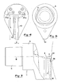
- is an end view of the tool seen from the front,
- Fig 5
- is an end view of the tool seen from behind,
- Fig 6
- is an enlarged planar view from above of the same tool,
- Fig 7
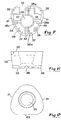
- is an enlarged planar view of the cutting insert of the tool seen from below,
- Fig 8
- is an end view of the cutting insert according to
fig 7 , - Fig 9
- is a planar view from above of the same cutting insert,
- Fig 10
- is an additional enlarged planar view from above of the cutting insert, the geometry of the cutting insert being illustrated in detail,
- Fig 11
- is a partially cut perspective view showing the tool in connection with a partially shown workpiece,
- Fig 12
- is a planar view from above showing the tool during machining of a workpiece, wherein it should be noted that the cutting insert is right-hand mounted seen based on the basic body,
- Fig 13
- is an analogous planar view showing an alternative embodiment having a left-hand mounted cutting insert, and
- Figs 14-16
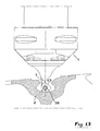
- are partial planar views showing the tool in three different positions during operation.
- In
figs 1 and 2 , a tool is shown in the form of a turning tool, which comprises abasic body 1 and acutting insert 2, which is detachably mounted on the basic body. In the example, thebasic body 1 includes a cylindricalmain part 3 from the back side of which acoupling element 4 extends, which is possible to fix in a machine tool (not shown). In the front, the basic body has a bracket in its entirety designated 5 having a cuttingseat 6 in which thecutting insert 2 is possible to fix. Said bracket includes anarrow neck part 7 and asupport part 8 protruding laterally from the same. - The cutting
insert 2 will be described more in detail below, reference being made tofigs 7-10 . - Now reference is also made to
figs 3-6 , which together withfigs 1 and 2 illustrate the design of thebracket 5 in detail. Infig 6 is seen how the comparativelythin neck part 7 is delimited by two planar,opposite side surfaces support part 8 projects only from one of the sides of the neck part, viz. towards the right seen from the basic body. Theright side surface 9 of theneck part 7 transforms via a transition line 11 (seefigs 2 and3 ) into a limiting surface designated 12, which also is delimited by anedge line 13 distanced from thetransition line 11. From said edge line, a convexly curvedfront surface 14 extends, which in the area thereof opposite theedge line 13 continuously transforms into theplanar side surface 10 of theneck part 7. At the top, i.e. in connection with the cuttingseat 6, the limitingsurface 12 is planar, as is outlined by means of thestraight edge line 15 infig 6 . Thesupport part 8 tapers in the backward direction or downwards from the cuttingseat 6 towards alower end surface 16. More precisely, the support part tapers in two different planes, because not only thetransition line 11, but also theedge line 13, is arched, as is clearly seen infig 3 and fig 4 together. As a consequence of theedge line 13 having said arc-shape, the limitingsurface 12 tapers in the direction from the cutting seat towards the lower end of the support part, the limiting surface simultaneously having a convexly curved shape in the longitudinal direction thereof (also cross-section-wise the limitingsurface 12 may have a weakly curved shape). - In order to guarantee a good stability of the cutting insert during operation, the described bracket has a considerable length such as this is counted from the cutting
seat 6 to thelower end surface 16. Thus, in practice, the length L of the bracket (seefig 4 ) should be at least 3, suitably 5 times greater than the width B such as this is counted in the area of the cuttingseat 6. In the example according tofig 4 , the length L is approx. 5,6 times greater than the width B. In relation to the thickness of the cutting insert 2 (such as this is counted between the top and bottom sides of the cutting insert), the length L of the bracket should be at least 5, suitably at least 10 times greater than the thickness of the cutting insert. In the example, the length of the bracket L is approx. 11 times greater than the thickness of the cutting insert. - Reference is now made to
fig 12 , which illustrates the turning tool according to the invention together with aworkpiece 17 in the form of a so-called coil to a jet engine. Said workpiece has a rotationally symmetrical, more preciselyconical envelope surface 18, in which continuous, ring-shapedgrooves 19 should be shaped. During turning, theworkpiece 17 rotates around a geometrical centre axis that in reality is situated at a comparatively large distance from the envelope surface, but which for technical reasons of drawing, is shown by means of the dash-dotted line C fairly near the envelope surface. Theindividual groove 19 is formed with anouter gap 20 and a countersunkhollow space 21 located inside the same, which hollow space has a greater width than thegap 20. Saidhollow space 21 is delimited by a bottom 22 and two concavely curvedside limiting surfaces 24, which transform into planar shoulder surfaces 23, which are inclined in relation to the centre axis C and converge in the direction outwards towards thegap 20. - A radial plane perpendicular to the rotational axis C of the
workpiece 17 is infig 12 designated R. The same radial plane R coincides with a vertical, central reference plane through the tool. The designation R will therefore henceforth be used in order to denote the central reference plane through the tool as well as a radial plane through the gap. The radial plane R is located halfway between the twoshoulder surfaces 23 and forms therefore also a symmetry plane for thegroove 19. In relation to said symmetry plane, the shoulder surfaces in the example extend at approx. 45° angle, the supplementary angle α amounting to 135°. - Now reference is made again to
figs 1-6 ,fig 6 of which illustrates how theedge line 15, which partly defines the cuttingseat 6, extends at an obtuse angle β to the reference plane R. Said angle β should always be smaller than the above-mentioned angle α. In the example shown, when the angle α is 135°, the angle β amounts to 132°. This means that theedge line 15 clears approx. 3° from theshoulder surface 23 of thehollow space 21. - Depending on the angle of inclination of the shoulder surfaces 23, the above-mentioned angle β may vary. However, it should amount to at least 125°, or preferably at least 130°, and at most 140°, or preferably at most 135°.
- In
figs 3 and 5 is seen how thecoupling element 4 on the back side of thecylinder part 3 tapers in the backward direction, as well as has a so-called polygon-shaped cross-section. More precisely, the cross-section shape of theelement 4 is determined by three triangle-like, convexly curved main surfaces which transform into each other via rounded corners having considerably smaller bending radius than the main surfaces. A coupling element of this type (which is commercially available under the trade name COROMANT CAPTO ®) guarantees an absolutely rigid connection between the tool and the appurtenant tool holder. - On the front side of the
cylinder part 3 of thebasic body 1, anozzle plate 25 is arranged having a number ofnozzles 25a (seefigs 1 and4 ) by means of which a cooling fluid can be sprayed against the cuttinginsert 2, more precisely against the top side of the same. In the example, twonozzles 25a are included in the plate, viz. one to the left and one to the right, for spraying a fluid with low pressure. The plate could also be supplemented with high pressure nozzles. Furthermore, a coolingfluid conduit 26 mouths in thesupport part 8 of thebracket 5 with the purpose of from below spraying a cooling fluid against the cutting insert. - In
fig 3 , M designates a conceived centre line through thecoupling element 4 and thecylindrical part 3 of thebasic body 1. As is clearly seen infig 3 , the cuttinginsert 2 is located approximately on a level with said centre line. More precisely, the top side of the cuttinginsert 2 is located in the extension of the centre line M, the supportingbracket 5 for the cutting insert extending downwards from the centre line M. Furthermore, the bracket has such a length that the lower portion of the same projects an important distance under the envelope surface of thecylinder part 3. Advantageously, the length of the bracket is more than 50 % greater than the circle radius for the envelope surface of thecylinder part 3. - With particular reference to
fig 6 , it should be pointed out that theside surface 9 of theneck part 7 is situated substantially in the reference plane R, i.e. the central plane that intersects the basic body vertically. This means that thesupport part 8 in its entirety projects sidewards from the material portion that is delimited by theside surface 10 and a conceived extension of the reference plane R. A threadedhole 27 for a fixing screw 28 (seefig 2 ) for fixation of the cutting insert is symmetrically located in relation to the reference plane R (the centre of the hole is situated in the plane R). Between theinclined edge 15 of thesupport part 8 and a correspondingly inclined limitingsurface 29 on the basic body, a cross-section-wise V-shapedspace 30 is defined. If thesurface 29 is inclined in the same angle to the reference plane R as theedge 15, the angle of aperture of the V-space 30 will amount to 84°. - Characteristic of the cutting
insert 2, which is visualised in detail infigs 7-10 , is that the same is indexable by including two spaced-apart, convexly arched and alternately applicable side cutting edges 31. In the usual way, the cutting insert is defined by atop side 32, abottom side 33 and acircumferential clearance surface 34, which extends between thetop side 32 and thebottom side 33. In the example, thetop side 32 is planar, and the cutting insert having a positive cutting geometry thanks to theclearance surface 34 extending at an acute angle γ to thetop side 32. In practice, the angle γ can amount to 83°, i.e. the clearance angle is 7°. In the cutting insert, a throughhole 35 is formed for the aforementioned fixingscrew 28. On the bottom side thereof, the cutting insert is formed with means in order to in co-operation with analogous means of the cuttingseat 6 prevent angular displacement of the cutting insert in the mounted state. Said means may advantageously consist of so-called cross serrations in the form of either scores or ridges on the cutting insert for engagement with a corresponding number of ridges or scores in the cutting seat. In the example shown, the cutting insert is formed with twoscores like lands 37 being defined. At the free corners of two of said lands, comparatively large L-shaped corner countersinks 38 are formed, while the two other lands are formed with analogous corner countersinks 39 which are smaller than thecountersinks 38. Each one of the twoscores central hole 35. In other words, the individual score consists of two flute formations located in line with each other, which are distanced from each other via the hole. - The co-operating coupling means in the cutting
seat 6 consist of tworidges fig 2 ), which extend at right angles to each other while forming a cross-like configuration of the same type as cross configuration of thescores corner projections 41 are formed intended to engage the aforementioned corner countersinks 38, 39 in the cutting insert. Between thecorner projections 41 and theridges tooth 37 on the cutting insert can engage. The depth of theridges scores screw 28. By means of the described coupling means, it is guaranteed that the cutting insert by the simple measure of fastening the screw is located in a very exactly defined position from which it is not dislodged by angular displacement or in another way. Therefore, in practice, the cutting insert can be mounted in the tool with a dimensional accuracy of 0,01 mm or finer. - As is best seen in
fig 10 , the cuttinginsert 2 has a generally heart-like contour shape, which is defined by the two side cutting edges 31 on both sides of a symmetry plane S, which intersects the centre of thehole 35. Perpendicularly to the symmetry plane S, the centre of thehole 27 is intersected by a second plane P. Because the two halves of the cutting insert that are spaced apart by the symmetry plane S are mirror-symmetrical, only one of the halves, viz. the left one infig 10 , will be described closer. The cutting edges 31 extend between a commonrear corner edge 42 and afront clearance edge 43, which in the example is straight. As is seen infig 10 , the cutting insert tapers from the area of the front clearance edge in the direction of the rear corner edge, more precisely as a consequence of the first-mentioned edge being considerably longer than the last-mentioned one. - Each individual
side cutting edge 31 is composed of a plurality ofpart cutting edges top side 32 of the cutting insert and the circumferential,smooth clearance surface 34. The contour shape of thebottom side 33, such as this is determined by a circumferential interruption line 48 (seefigs 7 and 8 ), corresponds generally to the contour shape of the cuttingseat 6. This means that theclearance surface 34 of the cutting insert is located in flush with the external surface of thesupport part 8. In other words, theclearance surface 34 of the cutting insert connects to the outside of thesupport part 8 without forming any abrupt projections in the interface between the cutting insert and the support part. Because the cutting insert has a positive cutting geometry so far that theclearance surface 34 extends at the acute angle γ to the top side, thetop side 32 receive a larger surface extension than the bottom side 33 (a projection of the outer edge of thetop side 32 perpendicularly to the plane of the cutting insert is accordingly located outside theinterruption line 48 from all sides). - It should be noted that the
edges 42 and 43 - which both are straight - are parallel with each other. - Reference being made to
fig 10 , a concrete example of the shape and the dimensions of a cutting insert according to the invention will follow below. In this case, the cutting insert has a width W of 9 mm (W/2 = 4,5 mm) and a length I of 8,5 mm. The distances D1, D2 between the plane P and theclearance edge 43 and thecorner edge 42, respectively, is equally large and amounts to 4,25 mm. In other words, the centre of thehole 35 is located halfway between theedges corner edge 42 is straight and transforms into the part cutting edge 46 via apart cutting edge 47 having a radius R4 of 2,5 mm. The distance D3 between the symmetry plane S and the point where thecorner edge 42 transforms into thepart cutting edge 47 amounts to 0,3 mm. The centre E for the radius R3 of the part cutting edge 46 is situated to the right of the symmetry plane S and above the plane P. In other words, the individual part cutting edge 46 (which is longest of all part cutting edges 44, 45, 46, 47) has the centre E thereof located on the half of the cutting insert defined by the symmetry plane S which is opposite said part edge, as well as on the front part of the cutting insert, i.e. between the plane P and thefront clearance edge 43. From said point E, a line F extends perpendicularly to the symmetry plane S. Where said line F intersects the left edge of the cutting insert, the part cutting edge 46 transforms into apart cutting edge 45, which in turn transforms into thepart cutting edge 44. Thepart cutting edge 45 has a radius R2 of 2,1 mm and an arc angle b2 of approx. 43,5°, while thepart cutting edge 44 has a (somewhat larger) radius R1 of 2,2 mm and an arc angle b1 of 46,5°. The arc angle b3 of the part cutting edge 46 amounts to 48,5°, while the arc angle B4 of thepart cutting edge 47 is 41,5°. The distance D4 between the plane P and the point E amounts to 2,1 mm, while the distance D5 (=half the length of the clearance edge 43) amounts to 2,3 mm. In other words, theclearance edge 43 has a length of 4,6 mm. It is axiomatic that the formedcutting edges 31 are mirror-inverted and equidistantly distanced from the symmetry plane S. - From what has been said above, it is clear that the bending radius R3 of the longest part cutting edge 46 is greater than the bending radius of each one of the other
part cutting edges - Furthermore, it should be noted that the total arc angle (b1 + b2 = 90°) for the part cutting edges 44, 45 is considerably greater than the arc angle (b3 = 48,5°) for the longest part cutting edge 46.
- In
fig 11 the described tool is shown during machining of theworkpiece 17. In the figure, T designates a conceived tangent line to the circumferentialcircular groove 19, which is turned in the rotationally symmetrical workpiece, while the dash-dotted line G marks a plane perpendicular to the tangent line T. If the tangent line T is vertical, the plane G is accordingly horizontally oriented (the line G extends in the extension of a conceived radius between the geometrical rotational axis of the workpiece and the periphery). As is shown by means of the line H, the cuttinginsert 2 is oriented at a certain, limited angle δ to the plane G. saidangle 5 has to be smaller than the clearance angle of the cutting insert (= 7°) and may in practice be within the range of 1-4°. - The function of the tool is described below, reference being made to
figs 13-16 , which show a tool having a left-hand mounted cutting insert. In this connection, it should be pointed out that one and the same cutting insert according to the invention can universally be used for both types of tools, i.e. for right-hand cutting as well left-hand cutting tools. - In a preparatory step, a groove having a quadrangular cross-section shape is rough-turned by means of a conventional, slotting tool (not shown), as is outlined by means of the parallel dash-dotted
lines 49 infig 14 . In the next step, in the bottom surface of the groove ashallow countersink 50 is turned by means of a round cutting insert (not shown) in order to form a clearance. In practice, said countersink may have a depth of approx. 0,05 mm. After this, forming follows of the desired profile of the innerhollow space 21 that widens inwards in the workpiece. Said profile forming is begun with a machining of one side of the groove. More precisely, the cuttinginsert 2 is inserted obliquely from outside, e.g. at an angle of 45°, as is shown by means of the arrow infig 14 . During the motion thereof into the workpiece, the tool is controlled in a determined, desired track of motion by means of suitable software. In this connection, chip removal takes place along the part cutting edges on the cutting insert that extend clockwise from the contact point Q. From the point Q, theaforementioned clearance edge 43 extends rearwards at a certain angle to the linear track of motion in which the point Q moves when the cutting insert is moved in the direction of the arrow infig 14 . More precisely, theedge 43 is somewhat inclined counter-clockwise in relation to said track of motion. This means that theedge 43 clears from the machined surface, as is clearly shown infig 15 . - In practice, the machining can be effected in one single step or pass. The cutting insert is then inserted obliquely laterally according to
fig 14 into the desired cutting depth, and then the same is inserted towards the centre of the groove in the direction of the arrow according tofig 16 . When the machining of theinclined shoulder surface 23 has been completed and the point Q reaches the position according tofig 15 , the cutting insert assumes a position in which the contour shape of the cutting edge from the point Q approximately up to the edge 47 (seefig 10 ) decides the final profile shape in one side of the groove. From the position according tofig 15 , the cutting insert is brought perpendicularly to the symmetry plane R of the groove in the direction inwards in order to finally clear when the same reaches up to the countersink. - The opposite side of the groove is turned in the same way, but by means of a tool having a right-hand mounted cutting insert (according to
fig 12 ). - A fundamental advantage of the tool according to the invention is that the same is robust and thereby ensures a stable, vibration-free turning, which results in the machined surfaces, in particular the vital, inclined shoulder surfaces in the hollow space of the groove becoming smooth and dimensionally accurate. To said stability, a plurality of factors contribute. Among other things, the described rudge teeth or locking means in the interface between the cutting insert and the cutting seat guarantee that the cutting insert can be located in a very exactly definable position, as well as be retained in a reliable way in the same position during turning. In doing so, the long bracket and the appurtenant support part ensure that the cutting insert in an exact way maintains the tangential position thereof in relation to the rotary workpiece also in situations when the cutting insert is exposed to very large cutting forces. Also the described coupling element in the rear part of the basic body contributes to the stability of the tool. By the fact that said coupling element (in a known way, per se) has a tapering shape and a polygon-shaped cross-section, an extremely good fixation of the basic body in the appurtenant machine is guaranteed. In this way, each tendency of the basic body and the cutting insert, respectively, to be angularly displaced is counteracted in an effective way. Another advantage is that one and the same cutting insert is universally usable for right-hand turning as well as left-hand turning tools. By the unique, tapering shape of the support part of the insert-carrying bracket, it is further guaranteed that the cutting insert can be inserted into the described groove and machine an inwardly turned shoulder surface without the bracket colliding with the workpiece. Since the cutting insert is fed-in obliquely, e.g. at an angle of 45°, in the groove and has a positive chip angle, the released chip will exit the groove via the thin gap without hitting the opposite side of the groove. In other words, chip stopping is avoided. This in turn entails that the need for after-treatment disappears or is reduced. Also, the number of requisite finishing steps is reduced, more precisely to two, viz. a machining of the left side of the groove and a machining of the right side thereof. The work of getting the desired grooves ready is furthermore shortened by the fact that the tools can be mounted and removed with minimal set-up times.
- The invention is not limited only to the embodiments described above and shown in the drawings. Thus, the basic body included in the tool as well as the replaceable cutting inserts may be modified in miscellaneous ways within the scope of the appended claims. For instance, it is feasible for fixation of the cutting insert in the cutting seat of the basic body to use other means than cross serrations of the type that is exemplified in the drawings. Although the cutting insert suitably has a heart-like contour shape, the individual details may be modified. For instance, the long clearance edge extending between the two cutting edges may be formed concavely arched instead of straight.
- In conclusion, it should be pointed out that the described tool primarily is intended for turning in metallic workpieces, the basic body advantageously being made from steel or the like, while the cutting insert is made from cemented carbide, ceramic metals or the like.
-
- 1
- Basic body
- 2
- Cutting insert
- 3
- Cylinder part
- 4
- Coupling element
- 5
- Bracket
- 6
- Cutting seat
- 7
- Neck part
- 8
- Support part
- 9
- Side surface of neck part
- 10
- Side surface of neck part
- 11
- Transition line
- 12
- Limiting surface
- 13
- Edge line of support part
- 14
- Front surface of bracket
- 15
- Edge line along cutting seat
- 16
- Lower end surface of bracket
- 17
- Workpiece
- 18
- Envelope surface of workpiece
- 19
- Ring-shaped groove in workpiece
- 20
- Outer gap in groove
- 21
- Hollow space
- 22
- Bottom in hollow space
- 23
- Shoulder surfaces
- 24
- Side limiting surfaces
- 25
- Nozzle plate
- 25a
- Nozzles
- 26
- Cooling fluid conduit
- 27
- Hole for fixing screw
- 28
- Fixing screw
- 29
- Limiting surface of basic body
- 30
- V-space
- 31
- Cutting edges
- 32
- Top side of cutting insert
- 33
- Bottom side of cutting insert
- 34
- Clearance surface of cutting insert
- 35
- Hole in cutting insert
- 36
- Scores in cutting insert
- 37
- Land of cutting insert
- 38
- Corner countersink in cutting insert
- 39
- Corner countersink in cutting insert
- 40
- Ridges in cutting seat
- 41
- Corner projections of cutting seat
- 42
- Rear corner edge of cutting insert
- 43
- Front clearance edge of cutting insert
- 44
- Part cutting edge of cutting insert
- 45
- Part cutting edge of cutting insert
- 46
- Part cutting edge of cutting insert
- 47
- Part cutting edge of cutting insert
- 48
- Contour line of cutting insert
- 49
- Groove limitation lines
- 50
- Bottom countersink
Claims (25)
- Tool for the fine turning of rotationally symmetrical grooves (19) in workpieces, comprising a basic body (1) and a cutting insert (2), which is delimited by a top side (32), a bottom side (33) and at least one clearance surface (34) between the same, and which is possible to fix in a cutting seat (6) on a bracket (5) included in the basic body, which bracket includes a narrow neck part (7) and a support part (8) protruding laterally from the same with the purpose of supporting a portion of the cutting insert (2) protruding laterally in relation to the neck part with the purpose of enabling, in a workpiece, the turning of internal shoulder surfaces (23) of a hollow space (21) countersunk inside a gap (20) of the groove (19) and having a greater width than the gap, characterized in that the cutting insert (2) is indexable by including two spaced-apart, convexly arched and alternately applicable side cutting edges (31), and has a hole (35) for a screw (28) by means of which the same can be clamped and fixed in the cutting seat (6) on the bracket (5), said cutting seat (6) and the bottom side (33) on the cutting insert (2) having co-operating means (36, 40) in order to prevent angular displacement of the cutting insert in relation to the cutting seat.
- Tool according to claim 1, characterized in that the bracket (5) has a length (L) that is at least 3 times greater than the width (B) counted in the area of said support part (8).
- Tool according to claim 1 or 2, characterized in that the length (L) of the bracket (5) is at least 5 times greater than the thickness of the cutting insert (2) such as this is counted between the top and bottom sides (32, 33) of the cutting insert.
- Tool according to any one of the preceding claims, characterized in that the neck part (7) of the bracket (5) is delimited by two planar, opposite side surfaces (9, 10), a first one of which (9) transforms into said support part (8) via an arched transition line or zone (11).
- Tool according to any one of the preceding claims, characterized in that the support part (8) tapers in the backward or downward direction from the cutting seat (6) in order to go free from the internal shoulder surface (23) in said hollow space (21).
- Tool according to claim 4 and 5, characterized in that the tapering shape of the support part (8) is defined not only by the transition line (11) between the support part and the first side surface (9) being arched, but also by an edge line or comb (13) formed on the support part and distanced from the transition line being arched.
- Tool according to any one of the preceding claims, characterized in that a cooling fluid conduit (26) mouths in the outside of the support part (8) in order to spray a cooling fluid in the direction of the cutting insert (2).
- Tool according to any one of the preceding claims, characterized in that the contour of the support part (8) in connection with the cutting seat (6) corresponds with the contour shape (48) of the bottom side (33) of a corner portion on the cutting insert that includes the side cutting edge (31), in order for a clearance surface (34) on the cutting insert to be located in flush with the outside of the support part (8).
- Tool according to any one of claims 4-8, characterized in that an edge (15) defining the cutting seat in connection with the first side surface (9) of the neck part (7) extends at an obtuse angle (β) of at least 125° and at most 140° to said side surface.
- Tool according to any one of the preceding claims, characterized in that the basic body (1) comprises a male-like, tapering coupling element (4) having a polygon-shaped cross-section.
- Tool according to any one of the preceding claims, characterized in that said means for preventing angular displacement of the cutting insert consists of cross serrations in the form of a plurality of scores (36a, 36b) - or ridges - of the cutting insert (2) oriented at an angle to each other for engagement with a corresponding number of ridges (40a, 40b) - or scores - of the cutting seat (6).
- Tool according to claim 9 and 11, characterized in that the scores are formed in the cutting insert and consist of two scores (36a, 36b), which are arranged perpendicularly to each other while forming a cross-like configuration, while the ridges are formed in the cutting seat (6) and consist of two ridges (40a, 40b), which have a shape mating the scores and are arranged perpendicularly to each other while forming a cross-like configuration, a first ridge (40a) being oriented perpendicularly to the limitation edge (15) of the cutting seat.
- Cutting insert for tool according to any one of the preceding claims, comprising a top side (32), a bottom side (33) and a clearance surface (34) between the same, as well as a hole (35) for a screw, characterized in that the same is indexable by including two spaced-apart, convexly arched side cutting edges (31), and that said bottom side (33) has means (36) in order to prevent angular displacement of the cutting insert.
- Cutting insert according to claim 13, characterized in that the same has a generally heart-like contour shape that is defined by two convexly arched edges (31), which form said side cutting edges, and are mirror-inverted and equidistantly distanced from a symmetry plane (S) intersecting the hole (35) via an intermediate, front clearance edge (43), the cutting insert tapering in the direction of a rear end distanced from said clearance edge (43).
- Cutting insert according to claim 12 or 13, characterized in that the individual side cutting edge (31) comprises a plurality of part cutting edges (44, 45, 46, 47) having different bending radii.
- Cutting insert according to claim 14 or 15, characterized in that the two side cutting edges (31) at the rear, thin end of the cutting insert are spaced-apart by a straight edge (42), which is parallel with the front clearance edge (43) and shorter than the same.
- Cutting insert according to claim 15 or 16, characterized in that a longest part edge (46) is circular arc-shaped and has the centre (E) thereof located, on one hand, on the half of the cutting insert, defined by the symmetry line (S), that is opposite said part edge, and, on the other hand, in an area between the front clearance edge (43) and a plane (P) that is perpendicular to the symmetry line (S) and intersects the centre axis of the hole (35).
- Cutting insert according to claim 14-17, characterized in that the front clearance edge (43) between the two side cutting edges (31) is straight and extends as a tangent in extension of a first part edge (44) in the two cutting edges (31).
- Cutting insert according to claim 17 or 18, characterized in that the bending radius (R3) of the longest part cutting edge (46) is at least twice as large as the bending radius (R1, R2, R4) of anyone of the other part cutting edges (44, 45, 47).
- Cutting insert according to any one of claims 13-19, characterized in that the means for preventing angular displacement on the bottom side consists of cross serrations in the form of a plurality of scores (36a, 36b) oriented at an angle to each other for engagement with a corresponding number of ridges (40a, 40b) in a cutting seat (6) on a tool basic body (1).
- Cutting insert according to claim 20, characterized in that two scores (36a, 36b) are arranged perpendicularly to each other while forming a cross-like configuration.
- Cutting insert according to claim 21, characterized in that a first score (36a) extends perpendicularly to the long clearance edge (43) of the cutting insert and is located halfway between the arched side cutting edges (31).
- Cutting insert according to claim 21 and 22, characterized in that the second score (36b) is located halfway between the front and rear limiting edges (43, 42) of the cutting insert and intersects the centre of the hole (27).
- Cutting insert according to any one of claims 13-23, characterized in that said top side (32) is planar, all edges or cutting edges (31, 42, 43) on the cutting insert being located in a common plane.
- Cutting insert according to any one of claims 13-24, characterized in that the same has a positive cutting geometry thanks to the clearance surface (34) between said top and bottom sides (32, 33) extending at an acute angle (γ) to the top side.
Applications Claiming Priority (3)
| Application Number | Priority Date | Filing Date | Title |
|---|---|---|---|
| SE0300696 | 2003-03-14 | ||
| SE0300696A SE526255C2 (en) | 2003-03-14 | 2003-03-14 | Tools and indexable inserts for fine turning of rotationally symmetrical grooves in workpieces |
| PCT/SE2004/000345 WO2004080631A1 (en) | 2003-03-14 | 2004-03-09 | Tool and cutting insert for the fine turning of grooves in workpieces |
Publications (2)
| Publication Number | Publication Date |
|---|---|
| EP1603698A1 EP1603698A1 (en) | 2005-12-14 |
| EP1603698B1 true EP1603698B1 (en) | 2010-05-05 |
Family
ID=20290672
Family Applications (1)
| Application Number | Title | Priority Date | Filing Date |
|---|---|---|---|
| EP04718783A Expired - Lifetime EP1603698B1 (en) | 2003-03-14 | 2004-03-09 | Tool and cutting insert for the fine turning of grooves in workpieces |
Country Status (7)
| Country | Link |
|---|---|
| US (1) | US7063487B2 (en) |
| EP (1) | EP1603698B1 (en) |
| CN (1) | CN100418678C (en) |
| AT (1) | ATE466681T1 (en) |
| DE (1) | DE602004027009D1 (en) |
| SE (1) | SE526255C2 (en) |
| WO (1) | WO2004080631A1 (en) |
Cited By (1)
| Publication number | Priority date | Publication date | Assignee | Title |
|---|---|---|---|---|
| EP4755550A1 (en) * | 2024-12-04 | 2026-06-10 | AB Sandvik Coromant | Method for machining a metal workpiece |
Families Citing this family (47)
| Publication number | Priority date | Publication date | Assignee | Title |
|---|---|---|---|---|
| IL158497A (en) * | 2003-10-20 | 2008-03-20 | Gil Hecht | Deburring tool and cutting insert therefor |
| US7300432B2 (en) * | 2004-04-21 | 2007-11-27 | Depuy Products, Inc. | Apparatus for securing a sensor to a surgical instrument for use in computer guided orthopaedic surgery |
| US7325471B2 (en) * | 2004-09-07 | 2008-02-05 | Kennametal Inc. | Toolholder and cutting insert for a toolholder assembly |
| SE527613C2 (en) * | 2004-10-15 | 2006-04-25 | Seco Tools Ab | Tool for cutting machining with a base plate with recesses |
| JP4830377B2 (en) * | 2005-07-11 | 2011-12-07 | コニカミノルタオプト株式会社 | Cutting tools |
| DE102006023740B4 (en) * | 2006-05-18 | 2017-05-11 | Kennametal Widia Produktions Gmbh & Co. Kg | Cutting insert and tool consisting of tool holder and cutting insert |
| US20070274794A1 (en) * | 2006-05-26 | 2007-11-29 | Cirino Thomas J | Oblique angle serration location and drive interface |
| SE530298C2 (en) * | 2006-09-12 | 2008-04-22 | Sandvik Intellectual Property | Cutting tools and inserts where the cutting edge of the cutting edge has a partially concave shape |
| SE530579C2 (en) * | 2006-11-28 | 2008-07-08 | Sandvik Intellectual Property | Tools and basic body for multi-channel chip separation machining |
| SE530581C2 (en) | 2006-11-28 | 2008-07-08 | Sandvik Intellectual Property | Chip separation tool and basic body comprising two channels for a fluid |
| SE530808C2 (en) * | 2007-01-31 | 2008-09-16 | Sandvik Intellectual Property | Tools for chip separating machining, as well as cutting and basic body for this |
| WO2011047126A1 (en) | 2009-10-15 | 2011-04-21 | Sandvik, Inc. | Multiteeth indexable insert with locating means and material removal tool with same |
| IL211113A (en) * | 2011-02-08 | 2015-09-24 | Iscar Ltd | Cutting tool and cutting insert therefor |
| DE102011016148B4 (en) * | 2011-03-28 | 2024-06-06 | Hartmetall-Werkzeugfabrik Paul Horn Gmbh | Tool for machining a workpiece with lateral coolant outlet and holder for the tool |
| US20120282048A1 (en) * | 2011-05-03 | 2012-11-08 | Diamond Innovations, Inc. | Insert With A Wiper To Induce Chip Thinning On A Leading Edge |
| US9120156B2 (en) * | 2013-03-26 | 2015-09-01 | Iscar, Ltd. | Rhombus-shaped indexable cutting insert and cutting tool |
| EP2898967B9 (en) † | 2014-01-27 | 2021-08-11 | Rosswag GmbH | Cutting tool holder, production method and use of a generative manufacturing device for manufacturing the cutting tool holder |
| CN105619168B (en) * | 2014-10-28 | 2017-12-22 | 富鼎电子科技(嘉善)有限公司 | Processing unit (plant) |
| US10507529B2 (en) * | 2015-07-24 | 2019-12-17 | Kyocera Corporation | Cutting tool and method of manufacturing machined product using the same |
| CN107052379B (en) * | 2017-03-01 | 2018-12-11 | 株洲钻石切削刀具股份有限公司 | Aperture knife tool in a kind of small-bore |
| CN109203725B (en) * | 2017-07-05 | 2023-08-04 | 康美包(苏州)有限公司 | Ink jet printer with print head protector |
| CN107470659B (en) * | 2017-08-29 | 2023-11-21 | 上海奥林汽车安全系统有限公司 | A tool for circular groove machining |
| CN107792752A (en) * | 2017-11-06 | 2018-03-13 | 张聿哲 | A kind of vertical transport bicycle system |
| EP3501701B1 (en) | 2017-12-22 | 2020-07-29 | Ceratizit Austria Gesellschaft m.b.H. | Tool system and method for turning |
| CN108569368A (en) * | 2018-01-03 | 2018-09-25 | 周长宾 | It is a kind of to determine the pseudo- trimaran of waterline buoyancy tank wheel propulsion |
| CN108057676B (en) * | 2018-02-05 | 2024-07-19 | 爱思恩梯(苏州)机床有限公司 | Automatic cleaning and detecting production line for gears of automobile gear box |
| EP3536428B2 (en) * | 2018-03-08 | 2026-03-25 | AB Sandvik Coromant | A turning method for a cnc-lathe and a turning tool |
| CN108406305B (en) * | 2018-04-13 | 2024-04-26 | 袁开靖 | Socket body capable of being symmetrically positioned in relative sliding mode and assembling method thereof |
| CN108571504A (en) * | 2018-05-08 | 2018-09-25 | 上海威纳工程技术有限公司 | Accurate pretension bolt |
| CN108555956A (en) * | 2018-07-01 | 2018-09-21 | 苏州华吉威自动化设备有限公司 | The jig of contour localization single-point absorption |
| CN109552268B (en) * | 2019-01-30 | 2023-09-26 | 广州市道诺电子科技有限公司 | Intelligent car washing equipment of split type control |
| CN110116351B (en) * | 2019-05-10 | 2024-06-11 | 河南华创通信设备有限公司 | Optical fiber end forming machine |
| JP6961900B2 (en) * | 2019-05-15 | 2021-11-05 | 住友電工ハードメタル株式会社 | Boring holders and turning tools |
| EP3738698B1 (en) * | 2019-05-16 | 2022-11-02 | AB Sandvik Coromant | Turning insert for metal cutting, a cutting tool and a method to machine a metal workpiece |
| CN110394491B (en) * | 2019-07-22 | 2024-08-02 | 河南北方红阳机电有限公司 | Coaxial double-edge cutter oblique insertion machining tool and machining method |
| EP3812066A1 (en) * | 2019-10-23 | 2021-04-28 | AB Sandvik Coromant | A tool holder and a parting and grooving tool for an indexable turret, and a machining method therefor |
| CN114787067B (en) * | 2019-12-13 | 2023-08-08 | 三菱电机株式会社 | Suspension body, method for manufacturing suspension body, method for assembling elevator, and elevator |
| JP6919824B2 (en) * | 2020-01-15 | 2021-08-18 | 株式会社タンガロイ | Cutting inserts and turning tools using the cutting inserts |
| CN112756580A (en) * | 2020-12-22 | 2021-05-07 | 闫哲 | Copper alloy bar extrusion forming die |
| CN113104249B (en) * | 2021-05-18 | 2024-01-05 | 正帆合泰(杭州)生物科技有限公司 | Metering device of liquid filling machine |
| CN113524356A (en) * | 2021-07-22 | 2021-10-22 | 山东中亿木业有限公司 | Fiber board edge rising prevention cutting device and using method thereof |
| CN113775577B (en) * | 2021-08-27 | 2024-01-30 | 中国煤炭科工集团太原研究院有限公司 | Built-in oil tank structure |
| CN114000839B (en) * | 2021-10-25 | 2023-09-15 | 西南石油大学 | A high-efficiency pipe string punching device |
| CN114770557A (en) * | 2022-05-30 | 2022-07-22 | 共享智能装备有限公司 | Truss robot |
| CN115446996B (en) * | 2022-07-21 | 2023-08-01 | 湖北国通领驭建设集团有限公司 | Reinforced concrete cutting equipment for hydropower installation of factory building |
| CN116460323A (en) * | 2023-05-17 | 2023-07-21 | 成都邦普切削刀具股份有限公司 | Cutting blade and cutting knife |
| EP4603215A1 (en) * | 2024-02-15 | 2025-08-20 | CERATIZIT Austria Gesellschaft m.b.H. | Machining cutting tool |
Family Cites Families (20)
| Publication number | Priority date | Publication date | Assignee | Title |
|---|---|---|---|---|
| SE452271B (en) * | 1982-04-01 | 1987-11-23 | Sandvik Ab | CUTS AND TOOLS FOR SPANISH WORKING |
| US5760015A (en) | 1988-01-19 | 1998-06-02 | The Trustees Of The University Of Pennsylvania | Cyclodextrin compounds and methods of making and use thereof |
| DE4018043A1 (en) * | 1990-06-06 | 1991-12-12 | Krupp Widia Gmbh | DRILLING TOOL |
| DE4244316C2 (en) * | 1992-12-28 | 2002-08-29 | Widia Gmbh | cutting tool |
| SE508387C2 (en) * | 1993-05-26 | 1998-10-05 | Sandvik Ab | round Cut |
| EP0906514B1 (en) | 1996-06-21 | 2001-10-24 | Siemens Aktiengesellschaft | Rotor for a turbomachine with blades insertable into grooves and blades for a rotor |
| SE511390C2 (en) * | 1997-03-05 | 1999-09-20 | Sandvik Ab | Device for clamping cutting plates for cutting metal machining |
| SE511565C2 (en) * | 1997-04-28 | 1999-10-18 | Sandvik Ab | Tools for cutting machining |
| SE509540C2 (en) * | 1997-06-30 | 1999-02-08 | Seco Tools Ab | Tool |
| SE513480C2 (en) * | 1998-01-27 | 2000-09-18 | Sandvik Ab | Cutting Tools |
| SE519123C2 (en) * | 1998-12-22 | 2003-01-14 | Seco Tools Ab | Cuts and tools for cutting machining and method of mounting cutters therein |
| SE514938C2 (en) * | 1999-09-02 | 2001-05-21 | Sandvik Ab | Cutting Tools |
| SE514939C2 (en) * | 1999-09-02 | 2001-05-21 | Sandvik Ab | Machine for chip separating machining and cutting tools for such machines |
| US6409435B1 (en) | 2000-07-03 | 2002-06-25 | Valenite Inc. | Cutting tool and method of locating cutting insert |
| IL145584A0 (en) * | 2000-10-02 | 2002-06-30 | Pfizer Prod Inc | Nmda nr2b antagonists for treatment |
| US6439851B1 (en) | 2000-12-21 | 2002-08-27 | United Technologies Corporation | Reduced stress rotor blade and disk assembly |
| AT410188B (en) * | 2001-01-18 | 2003-02-25 | Boehlerit Gmbh & Co Kg | CUTTING TOOL AND TABLE CUTTING PLATE |
| NO319690B1 (en) * | 2001-01-23 | 2005-09-05 | Teeness Asa | Cutter head for machine tools |
| SE521183C2 (en) * | 2001-03-15 | 2003-10-07 | Sandvik Ab | Cutting holder with means for adjusting the cutting position holder |
| US6796207B1 (en) * | 2002-08-09 | 2004-09-28 | Paul W. Long, Jr. | Machine tool support apparatus |
-
2003
- 2003-03-14 SE SE0300696A patent/SE526255C2/en not_active IP Right Cessation
-
2004
- 2004-03-09 EP EP04718783A patent/EP1603698B1/en not_active Expired - Lifetime
- 2004-03-09 WO PCT/SE2004/000345 patent/WO2004080631A1/en not_active Ceased
- 2004-03-09 AT AT04718783T patent/ATE466681T1/en not_active IP Right Cessation
- 2004-03-09 CN CNB2004800067896A patent/CN100418678C/en not_active Expired - Fee Related
- 2004-03-09 DE DE602004027009T patent/DE602004027009D1/en not_active Expired - Lifetime
- 2004-03-15 US US10/799,680 patent/US7063487B2/en not_active Expired - Lifetime
Cited By (2)
| Publication number | Priority date | Publication date | Assignee | Title |
|---|---|---|---|---|
| EP4755550A1 (en) * | 2024-12-04 | 2026-06-10 | AB Sandvik Coromant | Method for machining a metal workpiece |
| WO2026119444A1 (en) * | 2024-12-04 | 2026-06-11 | Ab Sandvik Coromant | Method for machining a metal workpiece |
Also Published As
| Publication number | Publication date |
|---|---|
| CN1758974A (en) | 2006-04-12 |
| SE0300696L (en) | 2004-09-15 |
| SE526255C2 (en) | 2005-08-09 |
| SE0300696D0 (en) | 2003-03-14 |
| DE602004027009D1 (en) | 2010-06-17 |
| US7063487B2 (en) | 2006-06-20 |
| WO2004080631A1 (en) | 2004-09-23 |
| US20040265074A1 (en) | 2004-12-30 |
| CN100418678C (en) | 2008-09-17 |
| EP1603698A1 (en) | 2005-12-14 |
| ATE466681T1 (en) | 2010-05-15 |
Similar Documents
| Publication | Publication Date | Title |
|---|---|---|
| US7063487B2 (en) | Tool and cutting insert for the fine turning of grooves in workpieces | |
| CN108290224B (en) | turning inserts | |
| JP4908201B2 (en) | Anti-rotation tool holder and cutting tip tool | |
| US11103929B2 (en) | Turning insert | |
| US20200406362A1 (en) | Turning method for a cnc-lathe | |
| JP7355736B2 (en) | turning inserts | |
| US20050023044A1 (en) | Cutting insert and milling cutter with such a cutting insert | |
| US20140010607A1 (en) | Milling insert | |
| JP2003334716A (en) | Indexable inserts and cutting tools | |
| WO2016083044A1 (en) | Rotatable tool for forming by metal cutting a circular groove | |
| CN108290231A (en) | Indexable insert blade type rotary cutting tool and blade | |
| US11597017B2 (en) | Turning tool and turning method for CNC-machines | |
| US11247280B2 (en) | Rotatable tool for forming by metal cutting a circular groove | |
| CN113396026B (en) | Turning insert for metal cutting | |
| JP2001025914A (en) | Indexable cutter | |
| JP2002166318A (en) | Milling tool |
Legal Events
| Date | Code | Title | Description |
|---|---|---|---|
| PUAI | Public reference made under article 153(3) epc to a published international application that has entered the european phase |
Free format text: ORIGINAL CODE: 0009012 |
|
| 17P | Request for examination filed |
Effective date: 20050708 |
|
| AK | Designated contracting states |
Kind code of ref document: A1 Designated state(s): AT BE BG CH CY CZ DE DK EE ES FI FR GB GR HU IE IT LI LU MC NL PL PT RO SE SI SK TR |
|
| AX | Request for extension of the european patent |
Extension state: AL LT LV MK |
|
| DAX | Request for extension of the european patent (deleted) | ||
| GRAP | Despatch of communication of intention to grant a patent |
Free format text: ORIGINAL CODE: EPIDOSNIGR1 |
|
| RIC1 | Information provided on ipc code assigned before grant |
Ipc: B23B 27/16 20060101ALI20091020BHEP Ipc: B23B 27/06 20060101AFI20091020BHEP |
|
| GRAS | Grant fee paid |
Free format text: ORIGINAL CODE: EPIDOSNIGR3 |
|
| GRAA | (expected) grant |
Free format text: ORIGINAL CODE: 0009210 |
|
| AK | Designated contracting states |
Kind code of ref document: B1 Designated state(s): AT BE BG CH CY CZ DE DK EE ES FI FR GB GR HU IE IT LI LU MC NL PL PT RO SE SI SK TR |
|
| REG | Reference to a national code |
Ref country code: GB Ref legal event code: FG4D |
|
| REG | Reference to a national code |
Ref country code: CH Ref legal event code: EP |
|
| REG | Reference to a national code |
Ref country code: IE Ref legal event code: FG4D |
|
| REF | Corresponds to: |
Ref document number: 602004027009 Country of ref document: DE Date of ref document: 20100617 Kind code of ref document: P |
|
| REG | Reference to a national code |
Ref country code: NL Ref legal event code: VDEP Effective date: 20100505 |
|
| PG25 | Lapsed in a contracting state [announced via postgrant information from national office to epo] |
Ref country code: SE Free format text: LAPSE BECAUSE OF FAILURE TO SUBMIT A TRANSLATION OF THE DESCRIPTION OR TO PAY THE FEE WITHIN THE PRESCRIBED TIME-LIMIT Effective date: 20100505 Ref country code: NL Free format text: LAPSE BECAUSE OF FAILURE TO SUBMIT A TRANSLATION OF THE DESCRIPTION OR TO PAY THE FEE WITHIN THE PRESCRIBED TIME-LIMIT Effective date: 20100505 Ref country code: ES Free format text: LAPSE BECAUSE OF FAILURE TO SUBMIT A TRANSLATION OF THE DESCRIPTION OR TO PAY THE FEE WITHIN THE PRESCRIBED TIME-LIMIT Effective date: 20100816 |
|
| PG25 | Lapsed in a contracting state [announced via postgrant information from national office to epo] |
Ref country code: SI Free format text: LAPSE BECAUSE OF FAILURE TO SUBMIT A TRANSLATION OF THE DESCRIPTION OR TO PAY THE FEE WITHIN THE PRESCRIBED TIME-LIMIT Effective date: 20100505 Ref country code: AT Free format text: LAPSE BECAUSE OF FAILURE TO SUBMIT A TRANSLATION OF THE DESCRIPTION OR TO PAY THE FEE WITHIN THE PRESCRIBED TIME-LIMIT Effective date: 20100505 Ref country code: FI Free format text: LAPSE BECAUSE OF FAILURE TO SUBMIT A TRANSLATION OF THE DESCRIPTION OR TO PAY THE FEE WITHIN THE PRESCRIBED TIME-LIMIT Effective date: 20100505 |
|
| PG25 | Lapsed in a contracting state [announced via postgrant information from national office to epo] |
Ref country code: CY Free format text: LAPSE BECAUSE OF FAILURE TO SUBMIT A TRANSLATION OF THE DESCRIPTION OR TO PAY THE FEE WITHIN THE PRESCRIBED TIME-LIMIT Effective date: 20100505 Ref country code: PL Free format text: LAPSE BECAUSE OF FAILURE TO SUBMIT A TRANSLATION OF THE DESCRIPTION OR TO PAY THE FEE WITHIN THE PRESCRIBED TIME-LIMIT Effective date: 20100505 Ref country code: GR Free format text: LAPSE BECAUSE OF FAILURE TO SUBMIT A TRANSLATION OF THE DESCRIPTION OR TO PAY THE FEE WITHIN THE PRESCRIBED TIME-LIMIT Effective date: 20100806 |
|
| PG25 | Lapsed in a contracting state [announced via postgrant information from national office to epo] |
Ref country code: EE Free format text: LAPSE BECAUSE OF FAILURE TO SUBMIT A TRANSLATION OF THE DESCRIPTION OR TO PAY THE FEE WITHIN THE PRESCRIBED TIME-LIMIT Effective date: 20100505 Ref country code: PT Free format text: LAPSE BECAUSE OF FAILURE TO SUBMIT A TRANSLATION OF THE DESCRIPTION OR TO PAY THE FEE WITHIN THE PRESCRIBED TIME-LIMIT Effective date: 20100906 Ref country code: DK Free format text: LAPSE BECAUSE OF FAILURE TO SUBMIT A TRANSLATION OF THE DESCRIPTION OR TO PAY THE FEE WITHIN THE PRESCRIBED TIME-LIMIT Effective date: 20100505 |
|
| PG25 | Lapsed in a contracting state [announced via postgrant information from national office to epo] |
Ref country code: SK Free format text: LAPSE BECAUSE OF FAILURE TO SUBMIT A TRANSLATION OF THE DESCRIPTION OR TO PAY THE FEE WITHIN THE PRESCRIBED TIME-LIMIT Effective date: 20100505 Ref country code: RO Free format text: LAPSE BECAUSE OF FAILURE TO SUBMIT A TRANSLATION OF THE DESCRIPTION OR TO PAY THE FEE WITHIN THE PRESCRIBED TIME-LIMIT Effective date: 20100505 Ref country code: CZ Free format text: LAPSE BECAUSE OF FAILURE TO SUBMIT A TRANSLATION OF THE DESCRIPTION OR TO PAY THE FEE WITHIN THE PRESCRIBED TIME-LIMIT Effective date: 20100505 Ref country code: BE Free format text: LAPSE BECAUSE OF FAILURE TO SUBMIT A TRANSLATION OF THE DESCRIPTION OR TO PAY THE FEE WITHIN THE PRESCRIBED TIME-LIMIT Effective date: 20100505 |
|
| PLBE | No opposition filed within time limit |
Free format text: ORIGINAL CODE: 0009261 |
|
| STAA | Information on the status of an ep patent application or granted ep patent |
Free format text: STATUS: NO OPPOSITION FILED WITHIN TIME LIMIT |
|
| 26N | No opposition filed |
Effective date: 20110208 |
|
| REG | Reference to a national code |
Ref country code: DE Ref legal event code: R097 Ref document number: 602004027009 Country of ref document: DE Effective date: 20110207 |
|
| PG25 | Lapsed in a contracting state [announced via postgrant information from national office to epo] |
Ref country code: MC Free format text: LAPSE BECAUSE OF NON-PAYMENT OF DUE FEES Effective date: 20110331 |
|
| REG | Reference to a national code |
Ref country code: CH Ref legal event code: PL |
|
| REG | Reference to a national code |
Ref country code: IE Ref legal event code: MM4A |
|
| PG25 | Lapsed in a contracting state [announced via postgrant information from national office to epo] |
Ref country code: LI Free format text: LAPSE BECAUSE OF NON-PAYMENT OF DUE FEES Effective date: 20110331 Ref country code: CH Free format text: LAPSE BECAUSE OF NON-PAYMENT OF DUE FEES Effective date: 20110331 Ref country code: IE Free format text: LAPSE BECAUSE OF NON-PAYMENT OF DUE FEES Effective date: 20110309 |
|
| PG25 | Lapsed in a contracting state [announced via postgrant information from national office to epo] |
Ref country code: LU Free format text: LAPSE BECAUSE OF NON-PAYMENT OF DUE FEES Effective date: 20110309 |
|
| PG25 | Lapsed in a contracting state [announced via postgrant information from national office to epo] |
Ref country code: BG Free format text: LAPSE BECAUSE OF FAILURE TO SUBMIT A TRANSLATION OF THE DESCRIPTION OR TO PAY THE FEE WITHIN THE PRESCRIBED TIME-LIMIT Effective date: 20100805 Ref country code: TR Free format text: LAPSE BECAUSE OF FAILURE TO SUBMIT A TRANSLATION OF THE DESCRIPTION OR TO PAY THE FEE WITHIN THE PRESCRIBED TIME-LIMIT Effective date: 20100505 |
|
| PG25 | Lapsed in a contracting state [announced via postgrant information from national office to epo] |
Ref country code: HU Free format text: LAPSE BECAUSE OF FAILURE TO SUBMIT A TRANSLATION OF THE DESCRIPTION OR TO PAY THE FEE WITHIN THE PRESCRIBED TIME-LIMIT Effective date: 20100505 |
|
| REG | Reference to a national code |
Ref country code: FR Ref legal event code: PLFP Year of fee payment: 13 |
|
| REG | Reference to a national code |
Ref country code: FR Ref legal event code: PLFP Year of fee payment: 14 |
|
| REG | Reference to a national code |
Ref country code: FR Ref legal event code: PLFP Year of fee payment: 15 |
|
| PGFP | Annual fee paid to national office [announced via postgrant information from national office to epo] |
Ref country code: DE Payment date: 20190226 Year of fee payment: 16 Ref country code: GB Payment date: 20190306 Year of fee payment: 16 |
|
| PGFP | Annual fee paid to national office [announced via postgrant information from national office to epo] |
Ref country code: FR Payment date: 20190226 Year of fee payment: 16 |
|
| REG | Reference to a national code |
Ref country code: DE Ref legal event code: R119 Ref document number: 602004027009 Country of ref document: DE |
|
| PG25 | Lapsed in a contracting state [announced via postgrant information from national office to epo] |
Ref country code: DE Free format text: LAPSE BECAUSE OF NON-PAYMENT OF DUE FEES Effective date: 20201001 Ref country code: FR Free format text: LAPSE BECAUSE OF NON-PAYMENT OF DUE FEES Effective date: 20200331 |
|
| GBPC | Gb: european patent ceased through non-payment of renewal fee |
Effective date: 20200309 |
|
| PG25 | Lapsed in a contracting state [announced via postgrant information from national office to epo] |
Ref country code: GB Free format text: LAPSE BECAUSE OF NON-PAYMENT OF DUE FEES Effective date: 20200309 |
|
| PGFP | Annual fee paid to national office [announced via postgrant information from national office to epo] |
Ref country code: IT Payment date: 20210211 Year of fee payment: 18 |
|
| PG25 | Lapsed in a contracting state [announced via postgrant information from national office to epo] |
Ref country code: IT Free format text: LAPSE BECAUSE OF NON-PAYMENT OF DUE FEES Effective date: 20220309 |
|
| P01 | Opt-out of the competence of the unified patent court (upc) registered |
Effective date: 20230526 |