EP1603259A1 - Method for receiving multicarrier signal and multicarrier receiver comprising it - Google Patents
Method for receiving multicarrier signal and multicarrier receiver comprising it Download PDFInfo
- Publication number
- EP1603259A1 EP1603259A1 EP03708493A EP03708493A EP1603259A1 EP 1603259 A1 EP1603259 A1 EP 1603259A1 EP 03708493 A EP03708493 A EP 03708493A EP 03708493 A EP03708493 A EP 03708493A EP 1603259 A1 EP1603259 A1 EP 1603259A1
- Authority
- EP
- European Patent Office
- Prior art keywords
- carrier signal
- carrier
- channel
- dimensions
- signal
- Prior art date
- Legal status (The legal status is an assumption and is not a legal conclusion. Google has not performed a legal analysis and makes no representation as to the accuracy of the status listed.)
- Granted
Links
Images






Classifications
-
- H—ELECTRICITY
- H04—ELECTRIC COMMUNICATION TECHNIQUE
- H04L—TRANSMISSION OF DIGITAL INFORMATION, e.g. TELEGRAPHIC COMMUNICATION
- H04L27/00—Modulated-carrier systems
- H04L27/26—Systems using multi-frequency codes
- H04L27/2601—Multicarrier modulation systems
- H04L27/2647—Arrangements specific to the receiver only
- H04L27/2649—Demodulators
- H04L27/265—Fourier transform demodulators, e.g. fast Fourier transform [FFT] or discrete Fourier transform [DFT] demodulators
-
- H—ELECTRICITY
- H04—ELECTRIC COMMUNICATION TECHNIQUE
- H04L—TRANSMISSION OF DIGITAL INFORMATION, e.g. TELEGRAPHIC COMMUNICATION
- H04L25/00—Baseband systems
- H04L25/02—Details ; arrangements for supplying electrical power along data transmission lines
- H04L25/0202—Channel estimation
- H04L25/0212—Channel estimation of impulse response
- H04L25/0216—Channel estimation of impulse response with estimation of channel length
-
- H—ELECTRICITY
- H04—ELECTRIC COMMUNICATION TECHNIQUE
- H04L—TRANSMISSION OF DIGITAL INFORMATION, e.g. TELEGRAPHIC COMMUNICATION
- H04L25/00—Baseband systems
- H04L25/02—Details ; arrangements for supplying electrical power along data transmission lines
- H04L25/0202—Channel estimation
- H04L25/0224—Channel estimation using sounding signals
- H04L25/0228—Channel estimation using sounding signals with direct estimation from sounding signals
- H04L25/023—Channel estimation using sounding signals with direct estimation from sounding signals with extension to other symbols
-
- H—ELECTRICITY
- H04—ELECTRIC COMMUNICATION TECHNIQUE
- H04L—TRANSMISSION OF DIGITAL INFORMATION, e.g. TELEGRAPHIC COMMUNICATION
- H04L25/00—Baseband systems
- H04L25/02—Details ; arrangements for supplying electrical power along data transmission lines
- H04L25/03—Shaping networks in transmitter or receiver, e.g. adaptive shaping networks
- H04L25/03006—Arrangements for removing intersymbol interference
- H04L25/03159—Arrangements for removing intersymbol interference operating in the frequency domain
-
- H—ELECTRICITY
- H04—ELECTRIC COMMUNICATION TECHNIQUE
- H04L—TRANSMISSION OF DIGITAL INFORMATION, e.g. TELEGRAPHIC COMMUNICATION
- H04L25/00—Baseband systems
- H04L25/02—Details ; arrangements for supplying electrical power along data transmission lines
- H04L25/03—Shaping networks in transmitter or receiver, e.g. adaptive shaping networks
- H04L25/03006—Arrangements for removing intersymbol interference
- H04L25/03178—Arrangements involving sequence estimation techniques
- H04L25/03248—Arrangements for operating in conjunction with other apparatus
- H04L25/03254—Operation with other circuitry for removing intersymbol interference
- H04L25/03261—Operation with other circuitry for removing intersymbol interference with impulse-response shortening filters
-
- H—ELECTRICITY
- H04—ELECTRIC COMMUNICATION TECHNIQUE
- H04L—TRANSMISSION OF DIGITAL INFORMATION, e.g. TELEGRAPHIC COMMUNICATION
- H04L25/00—Baseband systems
- H04L25/02—Details ; arrangements for supplying electrical power along data transmission lines
- H04L25/03—Shaping networks in transmitter or receiver, e.g. adaptive shaping networks
- H04L25/03006—Arrangements for removing intersymbol interference
- H04L2025/0335—Arrangements for removing intersymbol interference characterised by the type of transmission
- H04L2025/03375—Passband transmission
- H04L2025/03414—Multicarrier
-
- H—ELECTRICITY
- H04—ELECTRIC COMMUNICATION TECHNIQUE
- H04L—TRANSMISSION OF DIGITAL INFORMATION, e.g. TELEGRAPHIC COMMUNICATION
- H04L25/00—Baseband systems
- H04L25/02—Details ; arrangements for supplying electrical power along data transmission lines
- H04L25/03—Shaping networks in transmitter or receiver, e.g. adaptive shaping networks
- H04L25/03006—Arrangements for removing intersymbol interference
- H04L2025/03433—Arrangements for removing intersymbol interference characterised by equaliser structure
- H04L2025/03439—Fixed structures
- H04L2025/03522—Frequency domain
-
- H—ELECTRICITY
- H04—ELECTRIC COMMUNICATION TECHNIQUE
- H04L—TRANSMISSION OF DIGITAL INFORMATION, e.g. TELEGRAPHIC COMMUNICATION
- H04L25/00—Baseband systems
- H04L25/02—Details ; arrangements for supplying electrical power along data transmission lines
- H04L25/03—Shaping networks in transmitter or receiver, e.g. adaptive shaping networks
- H04L25/03006—Arrangements for removing intersymbol interference
- H04L2025/03433—Arrangements for removing intersymbol interference characterised by equaliser structure
- H04L2025/03535—Variable structures
- H04L2025/03547—Switching between time domain structures
- H04L2025/03566—Switching between time domain structures between different tapped delay line structures
- H04L2025/03585—Modifying the length
-
- H—ELECTRICITY
- H04—ELECTRIC COMMUNICATION TECHNIQUE
- H04L—TRANSMISSION OF DIGITAL INFORMATION, e.g. TELEGRAPHIC COMMUNICATION
- H04L27/00—Modulated-carrier systems
- H04L27/26—Systems using multi-frequency codes
- H04L27/2601—Multicarrier modulation systems
- H04L27/2602—Signal structure
- H04L27/2605—Symbol extensions, e.g. Zero Tail, Unique Word [UW]
-
- H—ELECTRICITY
- H04—ELECTRIC COMMUNICATION TECHNIQUE
- H04L—TRANSMISSION OF DIGITAL INFORMATION, e.g. TELEGRAPHIC COMMUNICATION
- H04L5/00—Arrangements affording multiple use of the transmission path
- H04L5/0001—Arrangements for dividing the transmission path
- H04L5/0003—Two-dimensional division
- H04L5/0005—Time-frequency
- H04L5/0007—Time-frequency the frequencies being orthogonal, e.g. OFDM(A) or DMT
Definitions
- the present invention relates to a method of receiving and processing a multi-carrier signal and a multi-carrier reception device employing the method and in particular relates to intersymbol interference equalization of received data in a multi-carrier reception device.
- OFDM Orthogonal Frequency Division Multiplexing
- MC-CDMA Code Division Multiple Access
- the OFDM system enables high bit rate transmission to be achieved using a plurality of mutually orthogonal narrow-band carriers.
- the frequency bandwidth is divided into small ranges and the respective divided ranges are processed using sub-carriers of low bit rate.
- the sub-carriers are not subject to frequency selective fading, so the multi-carrier modulation system is advantageous in respect of frequency selective fading.
- the CDMA technique is employed for OFDM modulation as a multiple access multiplexing technique.
- the respective user data are spread in the frequency region using orthogonal spread spectrum code, and are multiplexed with other user data that is spread using a different spread spectrum code.
- Figure 1 is an example of the layout of a MC-CDMA transmission device employing a prior art system as described above, in which a MC-CDMA transmission signal is generated and transmitted.
- binary data 1 is encoded using an encoder 2 of prescribed bit length and is modulated by a modulator 3 using a modulation system such as BPSK, QPSK or 16-QAM corresponding to the encoding.
- the modulated data is converted to Np1 data symbols using a serial/parallel converter 4.
- Np1 data symbols are simultaneously processed, a single data symbol being copied to a data set by a copier 5 using a spreading factor (SF).
- the transmission device transmits data using a number Np1*SF of sub-carriers.
- Data i.e. orthogonal code of length SF is multiplexed by a chip provided for each sub-carrier.
- the MC-CDMA transmission device spreads the signal in the frequency region using spreading code 6 and the inverse fast Fourier transformer (IFFT) 7 then performs inverse fast Fourier transformation with a number of dimensions equal to (Np1*SF). These are the main characteristics of an MC-CDMA system.
- the data set is converted to serial data by the parallel/serial converter 8 and, in order to remove intersymbol interference, an insertion section 8 inserts guard intervals GI.
- Figure 2 shows the layout of a MC-CDMA reception device corresponding to the MC-CDMA transmission device of Figure 1 using the prior art described above.
- the combining coefficients are multiplied with the output of the fast Fourier transformer 11 and code 12 that is the same as the spread spectrum code at the transmission end is multiplied therewith.
- ORC orthogonal restoring combining
- ECC equal gain combining
- MRC maximum ratio combining
- MMSEC minimum mean square error combining
- the output of the fast Fourier transformer 11 is accumulated in an accumulation section 14 matched with the intervals of the spreading factor (SF) of the frequency region, corresponding to the copying of the data sets in accordance with the spreading factor (SF) at the transmission end.
- the data symbols specific to a single user are thereby extracted.
- the signals accumulated by the accumulation section 14 are converted to serial signals by a parallel/serial converter 15, demodulated by a demodulator 16 and decoded by a decoder 17.
- Figure 3 and Figure 4 are respectively examples of the layout of an OFDM transmission device and reception device as employed in the conventional systems described above; they differ from the layout of the MC-CDMA transmission device of Figure 1 in that the spread spectrum processing using spread spectrum code and the inverse spread spectrum processing in the reception device are not performed.
- the rest of the layout is the same as that of the MC-CDMA transmission device and reception device shown in Figure 1 and Figure 2 so further description thereof is dispensed with.
- the OFDM transmission system is effective in regard to multi-path propagation and circuit distortion, but, in the extreme case, the maximum propagation delay becomes greater than the length of the guard intervals GI and, in the case where an adjacent symbol is affected by a preceding symbol i.e. in the case where intersymbol interference (ISI) occurs, is insufficient.
- ISI intersymbol interference
- An object of the present invention is therefore to provide a multi-carrier reception processing method that avoids such problems and a multi-carrier reception device using this.
- a first mode of achieving the above object of the present invention is characterized in that a multi-carrier signal in a multi-carrier system is received, a multi-carrier signal of an interval longer than one symbol of said received multi-carrier signal is selected, discrete Fourier transformation is performed on said selected multi-carrier signal, channel equalization is performed on said signal that has been subjected to said discrete Fourier transformation, and the dimensions of said channel-equalized signal are reduced to the dimensions of said received multi-carrier signal.
- a second mode of achieving the above object of the present invention is characterized in that, in the first mode, selection of said multi-carrier signal of interval longer than one symbol is performed in order to execute discrete Fourier transformation of greater length than the dimensions of said received multi-carrier signal.
- a third mode of achieving the above object of the present invention is characterized in that, in the first mode, said channel equalization is performed by multiplying the multi-carrier signal by equalization coefficients and in that the channel distortion effect of said received multi-carrier signal in the frequency region is thereby reduced.
- a fourth mode of achieving the above object of the present invention is characterized in that, in the first mode, orthogonal frequency division multiplexing is employed in said multi-carrier system.
- a fifth mode of achieving the above object of the present invention is characterized in that, in the first mode, multi-carrier code division multiple access is employed in said multi-carrier system.
- a sixth mode of achieving the above object of the present invention is characterized in that, in any of the first to the fifth modes, said received multi-carrier signal does not include guard intervals between adjacent symbol frames.
- a seventh mode of achieving the above object of the present invention is characterized in that, in the second mode, the discrete Fourier transformation of greater length than the dimensions of the multi-carrier signal is of a length which is an integral multiple of the dimensions of said multi-carrier signal.
- an eighth mode of achieving the above object of the present invention is characterized in that, in the seventh mode, an estimated value of the channel response with respect to said discrete Fourier transform output for each channel is found by interpolation of estimated values of reduced dimensions.
- the corresponding transmission device that is employed may have a layout as in the prior art layout shown in Figure 1 and Figure 3. Furthermore, as will be described later, as the multi-carrier reception device according to the present invention, a reception device may be employed that is capable of being applied also to reception of signals in which no guard intervals GI are inserted at the transmission end.
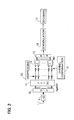
- Figure 5 is a block diagram of an example layout of an OFDM reception device according to the present invention.
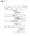
- Figure 6 is a flow chart given in explanation of the flow of processing corresponding to the example layout of the OFDM reception device of Figure 5; an outline of the necessary processing for equalization compensation of channel distortion, omitting the intersymbol interference (ISI) portion, is shown.
- ISI intersymbol interference
- the OFDM symbol length N is assumed to be much longer than the maximum amount of delay (expressed by ⁇ max ) from the channel model.
- the received signal train is first of all converted to a parallel signal by the serial/parallel converter 10.
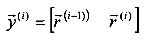
- 2 N data symbols are found from this parallel signal using a window (j-1, j) of size 2 N points, from two continuous symbol frames (see D1, Figure 6).
- Figure 6 shows how 2 N data symbols are successively found from two continuous symbol frames. Specifically, this Figure shows how 2 N data symbols are found from the (j-1)-th OFDM symbol frame and the j-th OFDM symbol frame and how 2 N data symbols are found from the j-th OFDM symbol frame and the (j+1)-th OFDM symbol frame.
- step S1 Discrete Fourier transformation of such 2 N data symbols is performed (step S1) by fast Fourier transformation processing performed by a 2 N point fast Fourier transformer 110, the construction of an embodiment of which is described later.
- channel compensation is performed by a distortion compensator 13 on the data (D2) that has been subjected to discrete Fourier transformation, in respect of each sub-carrier, in order to decrease channel distortion (step S2).
- the dimensions of the signal are reduced using a special transformation matrix 111, prior to demodulation using a demodulator 16.
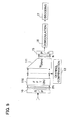
- Figure 7 shows an example layout of this transformation matrix 111.
- this comprises an inverse fast Fourier transformer (IFFT) 112 in respect of the 2 N points and a second IFFT 113 that, of the transformation processing output of the IFFT 112, performs inverse discrete Fourier transformation in respect of the subordinate N points.
- IFFT inverse fast Fourier transformer
- the inverse fast Fourier transformer (IFFT) 112 performs (step S3) inverse discrete Fourier transformation using inverse fast Fourier transformation on the channel-compensated data (D3).
- IFFT inverse fast Fourier transformer
- D4 inverse discrete Fourier transformed data
- D5 is obtained by performing an inverse discrete Fourier transformation (step S4) using the second IFFT 113, solely in respect of N points. In this way, the 2 N dimensions of the reception data are reduced to N dimensions.
- the reception data of N dimensions is converted to a serial signal by the parallel/serial converter 15 and is then subjected to demodulation using a demodulator 6 corresponding to the modulator 3 (see Figure 1) at the transmission end and decoding using a decoder 17 corresponding to the channel encoder 2.
- the principle of the present invention is that, in order to reduce the effect of intersymbol interference (ISI), the length on which fast Fourier transformation i.e. discrete Fourier transformation is performed is extended.
- ISI intersymbol interference
- FFT 2 N point fast Fourier transform
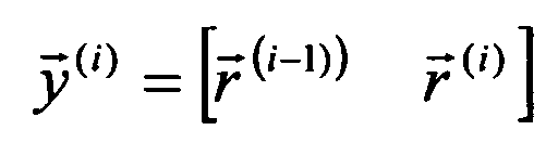
- the OFDM symbol length is assumed to be much larger than the amount of delay spreading, so only the residual portions of the received signals represent a combination of two continuous transmission symbols.
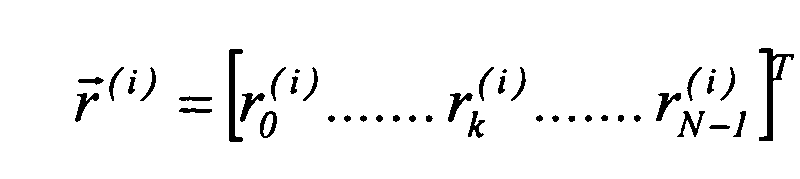
- reception signal r k (i) is represented as the following expression 1.
- intersymbol interference is moderated by equalization using extension of the discrete Fourier transformation length instead of canceling intersymbol interference.
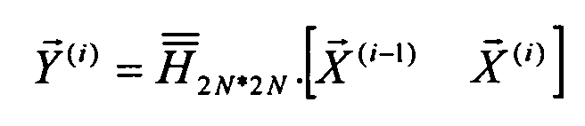
- G 2N*2N is a diagonal matrix constituted by complex numbers.
- the channel distortion compensation is expressed as follows in the frequency region. Consequently,
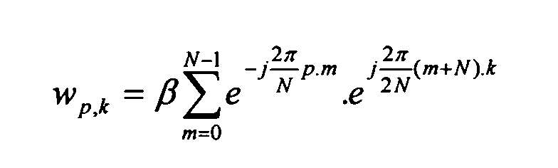
- the 2 N point signal is transformed to an N point signal stream by a special transformation matrix (transformation matrix 111 shown in Figure 5).
- the transformation matrix 111 is set as where ⁇ is a normalization coefficient
- the reception data found by processing using the above transformation matrix 111 is where, if guard intervals G1 are present, the selection of symbol blocks must be specified such that continuity between samples is maintained (i.e. orthogonality in the frequency region).
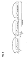
- Figure 8 is a view showing a 2 N continuous point cluster arrangement in the case where guard intervals GI are present.
- the thick arrows in the Figure indicate the arrangement of the guard intervals GI.
- 2 N points are obtained by combining the (j-1)-th OFDM symbol frame and the (j)-th OFDM symbol frame.
- a further 2 N points are obtained by combining the (j)-th OFDM symbol frame and the (j+1)-th OFDM symbol frame.
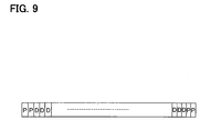
- Figure 9 shows an example of a frame in such a case.
- the two OFDM symbols (represented by P) of the head and the tail of each frame are pilot symbols recognized at the reception end.
- the channel compensation circuit 13 effects conversion to signals of the frequency region using N point fast Fourier transformation. It then estimates the channel response in respect of each sub-carrier for compensation of distortion, using the pilot symbols.
- the compensation coefficients based on the estimated channel response are then multiplied with the outputs of the 2 N dimensional fast Fourier transformer 110.
- a 2 N point channel response can be obtained by averaging from the estimated values obtained by interpolation as described next i.e. with N dimensions.
- this may be equivalently represented as follows.
- * is a convolution operator.
- the pilot series is subjected to inverse fast Fourier transformation at the transmission end and is received through a circuit (channel) at the reception end, where the corresponding fast Fourier transformation is performed.
- the channel response in respect of the 2 N point frequency region can therefore be obtained (see expression 4 or above) by interpolation. Finally, the compensation coefficients in respect of the various sub-carriers can be found from the estimated values of the channel response.
- FIG. 10 An embodiment of the layout of a reception device constituting a multi-carrier reception device according to the present invention in the case of MC-CDMA accompanying channel encoding and in which no guard intervals are employed is shown in Figure 10.
- the prior art layout ( Figure 1) may be employed at the transmission device end.
- equalization processing is performed in three steps.
- the fast Fourier transformer (FFT) 110 performs 2 N dimensional discrete Fourier transformation of length longer than a single MC-CDMA symbol on the FFT reception signal.
- the channel compensator 13 multiplies the output of the FFT transformer 110 by the equalization coefficients found from the channel estimated values.
- the dimensions of the signal are made equal to the N dimensions of the received MC-CDMA symbols.
- Reception data is converted to a parallel signal by the serial/parallel converter 10 and N point discrete Fourier transformation is then performed on N points by a fast Fourier transformer 1111.
- a serial data series is then obtained by a parallel/serial converter 112 in respect of these data that have been subjected to transformation processing.
- two continuous data series are obtained using a butterfly pattern (isomorphic mapping) 1114.
- the output of the fast Fourier transformer 1111 is directly output together with the output of the fast Fourier transformer 1111 to which a delay of one frame has been added by a delay element 1113, to the butterfly pattern (isomorphic mapping) 1114.
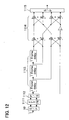
- FIG 12 shows the layout of an embodiment of the fast Fourier transformer (FFT) 110 in such a case of extension to 4 N dimensions.
- the butterfly pattern 1114 is implemented by performing synchronization by delay of three frames, performed by the frame delay element 1113.
- the portion indicated by j in the butterfly pattern 1114 of Figure 12 indicates the square root of "-1".
- transformer 111 corresponding to the fast Fourier transformer (FFT) 110 of Figure 12 needs to have a matrix of W4N*N so as to provide 4 N inputs.
- ISI intersymbol interference
Landscapes
- Engineering & Computer Science (AREA)
- Computer Networks & Wireless Communication (AREA)
- Signal Processing (AREA)
- Power Engineering (AREA)
- Physics & Mathematics (AREA)
- Discrete Mathematics (AREA)
- General Physics & Mathematics (AREA)
- Mathematical Physics (AREA)
- Cable Transmission Systems, Equalization Of Radio And Reduction Of Echo (AREA)
- Digital Transmission Methods That Use Modulated Carrier Waves (AREA)
Abstract
Description










Claims (16)
- A method of reception processing of a multi-carrier signal comprising the steps of:receiving a multi-carrier signal in a multi-carrier communications system;selecting a multi-carrier signal of an interval longer than one symbol of said received multi-carrier signal;performing discrete Fourier transformation on said selected multi-carrier signal;performing channel equalization on said discrete Fourier transformed signal; andreducing the dimensions of said channel equalized signal to the dimensions of said received multi-carrier signal.
- The method of reception processing of a multi-carrier signal according to claim 1, wherein selection of said multi-carrier signal of an interval longer than one symbol is performed in order to execute discrete Fourier transformation of length longer than the dimensions of said received multi-carrier signal.
- The method of reception processing of a multi-carrier signal according to claim 1, wherein said equalization is conducted by multiplying equalization coefficients by the multi-carrier signal so as to reduce the channel distortion effect of said received multi-carrier signal in the frequency region.
- The method of reception processing of a multi-carrier signal according to claim 1, wherein orthogonal frequency division multiplexing is employed in said multi-carrier communications system.
- The method of reception processing of a multi-carrier signal according to claim 1, wherein multi-carrier code division multiple access is employed in said multi-carrier communications system.
- The method of reception processing of a multi-carrier signal according to any of claims 1 to 5, wherein said received multi-carrier signal does not include guard intervals between adjacent symbol frames.
- The method of reception processing of a multi-carrier signal according to claim 2, the discrete Fourier transformation of length longer than the dimensions of the multi-carrier signal is of a length which is an integral multiple of the dimensions of said multi-carrier signal.
- The method of reception processing of a multi-carrier signal according to claim 7, the estimated value of the channel response with respect to said discrete Fourier transformed output of each channel is found by interpolating estimated values of reduced dimensions.
- A reception device for a multi-carrier signal in a multi-carrier system, comprising:a serial/parallel converter that receives a multi-carrier signal and converts this to a parallel signal;a Fourier transformer that selects a multi-carrier signal of an interval of length longer than one symbol of said received multi-carrier signal from the output of said serial/parallel converter and performs discrete Fourier transformation on said selected multi-carrier signal;a channel compensator that performs channel equalization on said discrete Fourier transformed signal;a matrix transformer that reduces the dimensions of said channel equalized signal to the dimensions of said received multi-carrier signal;a parallel/serial converter that converts the output of said matrix transformer to a serial signal; anda demodulator corresponding to the modulator and a decoder corresponding to the encoder at the transmission device side for the output of said parallel/serial converter.
- The reception device for a multi-carrier signal according to claim 9, wherein the length of the discrete Fourier transformation in said Fourier transformer corresponds to the length of said selected multi-carrier signal of an interval longer than said one symbol.
- The reception device for a multi-carrier signal according to claim 9, wherein the channel equalization performed by said channel compensator is conducted by multiplying equalization coefficients by the multi-carrier signal and thereby reducing the channel distortion effect of said received multi-carrier signal in the frequency region.
- The reception device for a multi-carrier signal according to claim 9, wherein orthogonal frequency division multiplexing is employed in said multi-carrier system.
- The reception device for a multi-carrier signal according to claim 9, wherein multi-carrier code division multiple access is employed in said multi-carrier system.
- The reception device for a multi-carrier signal to according to any of claims 9 to 13, wherein said received multi-carrier signal does not contain guard intervals between adjacent symbol frames.
- The reception device for a multi-carrier signal according to claim 10, wherein the discrete Fourier transformation of length longer than the dimensions of the multi-carrier signal is of length which is an integral multiple of the dimensions of said multi-carrier signal.
- The reception device for a multi-carrier signal according to claim 15, wherein the estimated values of the channel response with respect to said discrete Fourier transformed output of each channel are found by interpolation of estimated values of reduced dimensions.
Applications Claiming Priority (1)
| Application Number | Priority Date | Filing Date | Title |
|---|---|---|---|
| PCT/JP2003/002565 WO2004079958A1 (en) | 2003-03-05 | 2003-03-05 | Method for receiving multicarrier signal and multicarrier receiver comprising it |
Publications (3)
| Publication Number | Publication Date |
|---|---|
| EP1603259A1 true EP1603259A1 (en) | 2005-12-07 |
| EP1603259A4 EP1603259A4 (en) | 2010-04-07 |
| EP1603259B1 EP1603259B1 (en) | 2012-03-28 |
Family
ID=32948251
Family Applications (1)
| Application Number | Title | Priority Date | Filing Date |
|---|---|---|---|
| EP20030708493 Expired - Lifetime EP1603259B1 (en) | 2003-03-05 | 2003-03-05 | Method for receiving multicarrier signal and multicarrier receiver comprising it |
Country Status (4)
| Country | Link |
|---|---|
| US (1) | US20050232133A1 (en) |
| EP (1) | EP1603259B1 (en) |
| JP (1) | JP3998685B2 (en) |
| WO (1) | WO2004079958A1 (en) |
Families Citing this family (1)
| Publication number | Priority date | Publication date | Assignee | Title |
|---|---|---|---|---|
| WO2018071242A1 (en) | 2016-10-10 | 2018-04-19 | Kyocera Corporation | Layered data transmissions with geographical location dependent control information for machine type communication (mtc) devices |
Family Cites Families (14)
| Publication number | Priority date | Publication date | Assignee | Title |
|---|---|---|---|---|
| US5416767A (en) * | 1993-02-08 | 1995-05-16 | U.S. Philips Corporation | Method of transmitting a data stream, transmitter and receiver |
| JP3186464B2 (en) * | 1994-09-26 | 2001-07-11 | 日本コロムビア株式会社 | OFDM modulator and OFDM demodulator |
| JPH08316932A (en) * | 1995-05-17 | 1996-11-29 | Nippon Columbia Co Ltd | Ofdm demodulator |
| AT408396B (en) | 1998-12-21 | 2001-11-26 | Ericsson Austria Ag | METHOD FOR TRANSMITTING DATA |
| JP2000299673A (en) * | 1999-04-13 | 2000-10-24 | Toyota Central Res & Dev Lab Inc | Orthogonal frequency division multiplex modulation system and orthogonal frequency division multiplex modulation device, and orthogonal frequency division multiplex demodulation system and orthogonal frequency division multiplex demodulation device |
| JP4174905B2 (en) * | 1999-04-13 | 2008-11-05 | 株式会社豊田中央研究所 | Orthogonal frequency division multiplex modulation method and orthogonal frequency division multiplex modulation device, and orthogonal frequency division multiplex demodulation method and orthogonal frequency division multiplex demodulation device |
| JP2002064461A (en) * | 2000-08-18 | 2002-02-28 | Mitsubishi Electric Corp | Communication device and communication method |
| JP2002111622A (en) * | 2000-09-28 | 2002-04-12 | Mitsubishi Electric Corp | Communication device and communication method |
| CA2361247C (en) * | 2000-11-06 | 2008-10-07 | Ntt Docomo, Inc. | Transmitter, transmitting method, receiver, and receiving method for mc-cdma communication system |
| US6985533B2 (en) * | 2001-02-07 | 2006-01-10 | Agency For Science, Technology And Research | Method and apparatus for reducing peak to average power ratio in a multi-carrier modulation communication system |
| WO2002067527A2 (en) * | 2001-02-22 | 2002-08-29 | Koninklijke Philips Electronics N.V. | Multicarrier equalisation using multiplication by a leakage matrix |
| US7027519B2 (en) * | 2001-02-28 | 2006-04-11 | Mitsubishi Electric Research Laboratories, Inc. | Iterative maximum likelihood channel estimation and signal detection for OFDM systems |
| US20030023779A1 (en) * | 2001-07-13 | 2003-01-30 | Hideo Mizutani | Symbol window correlative operation circuit and address generation circuit therefor |
| DE10208717B4 (en) * | 2002-02-28 | 2004-04-01 | Infineon Technologies Ag | Method for transmitting an analog data stream with an increase in the sampling rate in the data stream transmitter and circuit arrangement for carrying out the method |
-
2003
- 2003-03-05 WO PCT/JP2003/002565 patent/WO2004079958A1/en not_active Ceased
- 2003-03-05 JP JP2004569089A patent/JP3998685B2/en not_active Expired - Fee Related
- 2003-03-05 EP EP20030708493 patent/EP1603259B1/en not_active Expired - Lifetime
-
2005
- 2005-04-01 US US11/097,979 patent/US20050232133A1/en not_active Abandoned
Also Published As
| Publication number | Publication date |
|---|---|
| EP1603259A4 (en) | 2010-04-07 |
| EP1603259B1 (en) | 2012-03-28 |
| US20050232133A1 (en) | 2005-10-20 |
| WO2004079958A1 (en) | 2004-09-16 |
| JPWO2004079958A1 (en) | 2006-06-08 |
| JP3998685B2 (en) | 2007-10-31 |
Similar Documents
| Publication | Publication Date | Title |
|---|---|---|
| JP5048481B2 (en) | Staggered pilot transmission for channel estimation and time tracking | |
| US7082159B2 (en) | Methods and arrangements in a telecommunications system | |
| AU2005208658B2 (en) | Time filtering for excess delay mitigation in OFDM systems | |
| KR100594084B1 (en) | Channel Estimation Method and Channel Estimator for Orthogonal Frequency Division Multiple Receiver | |
| US8050336B2 (en) | Frequency domain equalization method and apparatus for a single carrier receiver | |
| CN109861939B (en) | OQPSK frequency domain equalization wireless data transmission method | |
| KR20060000054A (en) | Hybrid Channel Estimation Method and System for High Speed Mobile Environment | |
| EP1894378A1 (en) | Receiver apparatus for receiving a multicarrier signal | |
| KR100764012B1 (en) | Channel Estimation Apparatus and Method for Delay Spread of Channel in Mobile Communication System | |
| CN100499610C (en) | Low complexity channel estimation method based on orthogonal sequence design | |
| KR101291683B1 (en) | Method of equalization for TDS-OFDM receiver and apparatus thereof | |
| JP5030311B2 (en) | Receiver, receiving method and integrated circuit | |
| CN101232358A (en) | A method and system for blind channel equalization in a multiple-input multiple-output system | |
| CN100505596C (en) | A Channel Estimation Method Applicable to Orthogonal Frequency Division Multiple Access System | |
| KR100664600B1 (en) | Curve Junction Channel Estimation Method in OFDM Systems | |
| US20070133393A1 (en) | Multi-carrier receiving method and multi-carrier receiving apparatus | |
| EP1603259A1 (en) | Method for receiving multicarrier signal and multicarrier receiver comprising it | |
| EP1679850A2 (en) | Pilot-based channel estimation method for mc-cdma system | |
| KR100781044B1 (en) | Channel Estimation System and Method for Wireless Communication System | |
| KR20050046209A (en) | A method for a channel estimation at a time-varying channel in an ofdm system with multiple transmit antennas | |
| KR101159122B1 (en) | Apparatus and method estimating of channel time delay in broadband wireless communication system | |
| Nair et al. | Channel estimation and equalization based on implicit training in OFDM systems | |
| KR100625075B1 (en) | Efficient Channel Estimation Method in Complex Channel Transceiver System | |
| JP2009267450A (en) | Receiving device and receiving method |
Legal Events
| Date | Code | Title | Description |
|---|---|---|---|
| PUAI | Public reference made under article 153(3) epc to a published international application that has entered the european phase |
Free format text: ORIGINAL CODE: 0009012 |
|
| 17P | Request for examination filed |
Effective date: 20050929 |
|
| AK | Designated contracting states |
Kind code of ref document: A1 Designated state(s): AT BE BG CH CY CZ DE DK EE ES FI FR GB GR IE IT LI LU MC NL PT SE SK TR |
|
| RBV | Designated contracting states (corrected) |
Designated state(s): DE FR GB |
|
| A4 | Supplementary search report drawn up and despatched |
Effective date: 20100304 |
|
| RIC1 | Information provided on ipc code assigned before grant |
Ipc: H04J 11/00 20060101AFI20040917BHEP Ipc: H04L 27/26 20060101ALI20100226BHEP Ipc: H04L 5/02 20060101ALI20100226BHEP |
|
| 17Q | First examination report despatched |
Effective date: 20100622 |
|
| GRAP | Despatch of communication of intention to grant a patent |
Free format text: ORIGINAL CODE: EPIDOSNIGR1 |
|
| RIC1 | Information provided on ipc code assigned before grant |
Ipc: H04L 27/26 20060101ALI20110912BHEP Ipc: H04J 11/00 20060101AFI20110912BHEP Ipc: H04L 5/02 20060101ALI20110912BHEP Ipc: H04L 25/03 20060101ALI20110912BHEP Ipc: H04L 25/02 20060101ALI20110912BHEP |
|
| GRAS | Grant fee paid |
Free format text: ORIGINAL CODE: EPIDOSNIGR3 |
|
| GRAA | (expected) grant |
Free format text: ORIGINAL CODE: 0009210 |
|
| AK | Designated contracting states |
Kind code of ref document: B1 Designated state(s): DE FR GB |
|
| REG | Reference to a national code |
Ref country code: GB Ref legal event code: FG4D |
|
| REG | Reference to a national code |
Ref country code: DE Ref legal event code: R096 Ref document number: 60340402 Country of ref document: DE Effective date: 20120524 |
|
| PGFP | Annual fee paid to national office [announced via postgrant information from national office to epo] |
Ref country code: FR Payment date: 20121130 Year of fee payment: 11 |
|
| PLBE | No opposition filed within time limit |
Free format text: ORIGINAL CODE: 0009261 |
|
| STAA | Information on the status of an ep patent application or granted ep patent |
Free format text: STATUS: NO OPPOSITION FILED WITHIN TIME LIMIT |
|
| 26N | No opposition filed |
Effective date: 20130103 |
|
| REG | Reference to a national code |
Ref country code: DE Ref legal event code: R097 Ref document number: 60340402 Country of ref document: DE Effective date: 20130103 |
|
| PGFP | Annual fee paid to national office [announced via postgrant information from national office to epo] |
Ref country code: GB Payment date: 20130102 Year of fee payment: 11 |
|
| REG | Reference to a national code |
Ref country code: DE Ref legal event code: R119 Ref document number: 60340402 Country of ref document: DE Effective date: 20131001 |
|
| PG25 | Lapsed in a contracting state [announced via postgrant information from national office to epo] |
Ref country code: DE Free format text: LAPSE BECAUSE OF NON-PAYMENT OF DUE FEES Effective date: 20131001 |
|
| GBPC | Gb: european patent ceased through non-payment of renewal fee |
Effective date: 20140305 |
|
| REG | Reference to a national code |
Ref country code: FR Ref legal event code: ST Effective date: 20141128 |
|
| PG25 | Lapsed in a contracting state [announced via postgrant information from national office to epo] |
Ref country code: FR Free format text: LAPSE BECAUSE OF NON-PAYMENT OF DUE FEES Effective date: 20140331 Ref country code: GB Free format text: LAPSE BECAUSE OF NON-PAYMENT OF DUE FEES Effective date: 20140305 |