EP1603033A2 - Verfahren und Vorrichtung zum Generieren von Formularen unter Verwendung von Formulartypen - Google Patents
Verfahren und Vorrichtung zum Generieren von Formularen unter Verwendung von Formulartypen Download PDFInfo
- Publication number
- EP1603033A2 EP1603033A2 EP05104721A EP05104721A EP1603033A2 EP 1603033 A2 EP1603033 A2 EP 1603033A2 EP 05104721 A EP05104721 A EP 05104721A EP 05104721 A EP05104721 A EP 05104721A EP 1603033 A2 EP1603033 A2 EP 1603033A2
- Authority
- EP
- European Patent Office
- Prior art keywords
- different
- logical
- generating
- run
- data model
- Prior art date
- Legal status (The legal status is an assumption and is not a legal conclusion. Google has not performed a legal analysis and makes no representation as to the accuracy of the status listed.)
- Ceased
Links
Images





Classifications
-
- G—PHYSICS
- G06—COMPUTING OR CALCULATING; COUNTING
- G06F—ELECTRIC DIGITAL DATA PROCESSING
- G06F8/00—Arrangements for software engineering
- G06F8/30—Creation or generation of source code
-
- A—HUMAN NECESSITIES
- A47—FURNITURE; DOMESTIC ARTICLES OR APPLIANCES; COFFEE MILLS; SPICE MILLS; SUCTION CLEANERS IN GENERAL
- A47G—HOUSEHOLD OR TABLE EQUIPMENT
- A47G9/00—Bed-covers; Counterpanes; Travelling rugs; Sleeping rugs; Sleeping bags; Pillows
- A47G9/10—Pillows
- A47G9/1036—Pillows with cooling or heating means
-
- A—HUMAN NECESSITIES
- A47—FURNITURE; DOMESTIC ARTICLES OR APPLIANCES; COFFEE MILLS; SPICE MILLS; SUCTION CLEANERS IN GENERAL
- A47C—CHAIRS; SOFAS; BEDS
- A47C27/00—Spring, stuffed or fluid mattresses or cushions specially adapted for chairs, beds or sofas
-
- A—HUMAN NECESSITIES
- A47—FURNITURE; DOMESTIC ARTICLES OR APPLIANCES; COFFEE MILLS; SPICE MILLS; SUCTION CLEANERS IN GENERAL
- A47G—HOUSEHOLD OR TABLE EQUIPMENT
- A47G9/00—Bed-covers; Counterpanes; Travelling rugs; Sleeping rugs; Sleeping bags; Pillows
- A47G9/007—Bed-covers; Counterpanes; Travelling rugs; Sleeping rugs; Sleeping bags; Pillows comprising deodorising, fragrance releasing, therapeutic or disinfecting substances
-
- A—HUMAN NECESSITIES
- A61—MEDICAL OR VETERINARY SCIENCE; HYGIENE
- A61F—FILTERS IMPLANTABLE INTO BLOOD VESSELS; PROSTHESES; DEVICES PROVIDING PATENCY TO, OR PREVENTING COLLAPSING OF, TUBULAR STRUCTURES OF THE BODY, e.g. STENTS; ORTHOPAEDIC, NURSING OR CONTRACEPTIVE DEVICES; FOMENTATION; TREATMENT OR PROTECTION OF EYES OR EARS; BANDAGES, DRESSINGS OR ABSORBENT PADS; FIRST-AID KITS
- A61F5/00—Orthopaedic methods or devices for non-surgical treatment of bones or joints; Nursing devices ; Anti-rape devices
- A61F5/56—Devices for preventing snoring
-
- G—PHYSICS
- G06—COMPUTING OR CALCULATING; COUNTING
- G06F—ELECTRIC DIGITAL DATA PROCESSING
- G06F8/00—Arrangements for software engineering
- G06F8/30—Creation or generation of source code
- G06F8/38—Creation or generation of source code for implementing user interfaces
Definitions
- the present invention relates to the generation of forms. More particularly, the present invention relates to methods and apparatus for generating and updating form user interfaces (UIs).
- UIs user interfaces
- a form is a window, a dialog, a page, or another UI element for viewing and/or entering data. It is not uncommon for the number of forms which are used in conjunction with a business software application to exceed several thousand. Developing a large number of forms has traditionally been a labor-intensive task for software developers.
- the present invention provides solutions to one or more of the above-described problems and/or provides other advantages over the prior art.
- a method, computer readable medium and system are provided which generate model driven form user interfaces to represent data models or models of a problem domain.
- a form user interface to represent a data model such as a business model
- a selection is made to identify which of a plurality of different logical form types is to be used to generate the form user interface to represent the data model.
- a logical form is generated at run-time using the data model and the selected logical form type.
- the form user interface is then also rendered at run-time using the generated logical form such that the data model is acted on at run-time.
- selecting which of the plurality of different logical form types to use to generate the form user interface further comprises selecting which of a plurality of different logical form type models to use to generate the user interface. Then, generating the logical form at run-time comprises generating the logical form at run-time using both the selected logical form type model and meta data from the data model.
- each of the plurality of different logical form types has an associated schema which defines data model data to be included in the generated logical form.
- the schema of each different logical form type represents patterns captured from a plurality of forms.
- generating the logical form at run-time further comprises generating the logical form using the associated schema.
- FIG. 1 illustrates an example of a suitable computing system environment 100 on which the invention may be implemented.
- the computing system environment 100 is only one example of a suitable computing environment and is not intended to suggest any limitation as to the scope of use or functionality of the invention. Neither should the computing environment 100 be interpreted as having any dependency or requirement relating to any one or combination of components illustrated in the exemplary operating environment 100.
- the invention is operational with numerous other general purpose or special purpose computing system environments or configurations.
- Examples of well known computing systems, environments, and/or configurations that may be suitable for use with the invention include, but are not limited to, personal computers, server computers, hand-held or laptop devices, multiprocessor systems, microprocessor-based systems, set top boxes, programmable consumer electronics, network PCs, minicomputers, mainframe computers, distributed computing environments that include any of the above systems or devices, and the like.
- the invention may be described in the general context of computer-executable instructions, such as program modules, being executed by a computer.
- program modules include routines, programs, objects, components, data structures, etc. that perform particular tasks or implement particular abstract data types.
- the invention may also be practiced in distributed computing environments where tasks are performed by remote processing devices that are linked through a communications network.
- program modules may be located in both local and remote computer storage media including memory storage devices.
- an exemplary system for implementing the invention includes a general purpose computing device in the form of a computer 110.
- Components of computer 110 may include, but are not limited to, a processing unit 120, a system memory 130, and a system bus 121 that couples various system components including the system memory to the processing unit 120.
- the system bus 121 may be any of several types of bus structures including a memory bus or memory controller, a peripheral bus, and a local bus using any of a variety of bus architectures.
- such architectures include Industry Standard Architecture (ISA) bus, Micro Channel Architecture (MCA) bus, Enhanced ISA (EISA) bus, Video Electronics Standards Association (VESA) local bus, and Peripheral Component Interconnect (PCI) bus also known as Mezzanine bus.
- ISA Industry Standard Architecture
- MCA Micro Channel Architecture
- EISA Enhanced ISA
- VESA Video Electronics Standards Association
- PCI Peripheral Component Interconnect
- Computer 110 typically includes a variety of computer readable media.
- Computer readable media can be any available media that can be accessed by computer 110 and includes both volatile and nonvolatile media, removable and non-removable media.
- Computer readable media may comprise computer storage media and communication media.
- Computer storage media includes both volatile and nonvolatile, removable and non-removable media implemented in any method or technology for storage of information such as computer readable instructions, data structures, program modules or other data.
- Computer storage media includes, but is not limited to, RAM, ROM, EEPROM, flash memory or other memory technology, CD-ROM, digital versatile disks (DVD) or other optical disk storage, magnetic cassettes, magnetic tape, magnetic disk storage or other magnetic storage devices, or any other medium which can be used to store the desired information and which can be accessed by computer 110.
- Communication media typically embodies computer readable instructions, data structures, program modules or other data in a modulated data signal such as a carrier wave or other transport mechanism and includes any information delivery media.
- modulated data signal means a signal that has one or more of its characteristics set or changed in such a manner as to encode information in the signal.
- communication media includes wired media such as a wired network or direct-wired connection, and wireless media such as acoustic, RF, infrared and other wireless media. Combinations of any of the above should also be included within the scope of computer readable media.
- the system memory 130 includes computer storage media in the form of volatile and/or nonvolatile memory such as read only memory (ROM) 131 and random access memory (RAM) 132.
- ROM read only memory
- RAM random access memory
- RAM 132 typically contains data and/or program modules that are immediately accessible to and/or presently being operated on by processing unit 120.
- FIG. 1 illustrates operating system 134, application programs 135, other program modules 136, and program data 137.
- a particular group of application programs are called business applications. These are targeted at the management of companies including - but not limited to - handling the general ledger, inventory, salaries, customers, sales, purchases, financial reports and any other data relevant for a business.
- the computer 110 may also include other removable/non-removable volatile/nonvolatile computer storage media.
- FIG. 1 illustrates a hard disk drive 141 that reads from or writes to non-removable, nonvolatile magnetic media, a magnetic disk drive 151 that reads from or writes to a removable, nonvolatile magnetic disk 152, and an optical disk drive 155 that reads from or writes to a removable, nonvolatile optical disk 156 such as a CD ROM or other optical media.
- removable/non-removable, volatile/nonvolatile computer storage media that can be used in the exemplary operating environment include, but are not limited to, magnetic tape cassettes, flash memory cards, digital versatile disks, digital video tape, solid state RAM, solid state ROM, and the like.
- the hard disk drive 141 is typically connected to the system bus 121 through a non-removable memory interface such as interface 140, and magnetic disk drive 151 and optical disk drive 155 are typically connected to the system bus 121 by a removable memory interface, such as interface 150.
- hard disk drive 141 is illustrated as storing operating system 144, application programs 145, other program modules 146, and program data 147. Note that these components can either be the same as or different from operating system 134, application programs 135, other program modules 136, and program data 137. Operating system 144, application programs 145, other program modules 146, and program data 147 are given different numbers here to illustrate that, at a minimum, they are different copies.
- a user may enter commands and information into the computer 110 through input devices such as a keyboard 162, a microphone 163, and a pointing device 161, such as a mouse, trackball or touch pad.
- Other input devices may include a joystick, game pad, satellite dish, scanner, or the like.
- These and other input devices are often connected to the processing unit 120 through a user input interface 160 that is coupled to the system bus, but may be connected by other interface and bus structures, such as a parallel port, game port or a universal serial bus (USB).
- the input devices are used for creating, modifying, and deleting data.
- Input devices can also be used for controlling (starting and stopping) the application programs and particular functions herein.
- the functions include opening (showing) forms and closing the forms.
- a monitor 191 or other type of display device is also connected to the system bus 121 via an interface, such as a video interface 190.
- computers may also include other peripheral output devices such as speakers 197 and printer 196, which may be connected through an output peripheral interface 195.
- the monitor or other display device is used to show (render) forms.
- the computer 110 may operate in a networked environment using logical connections to one or more remote computers, such as a remote computer 180.
- the remote computer 180 may be a personal computer, a hand-held device, a server, a router, a network PC, a peer device or other common network node, and typically includes many or all of the elements described above relative to the computer 110.
- the logical connections depicted in FIG. 1 include a local area network (LAN) 171 and a wide area network (WAN) 173, but may also include other networks.
- LAN local area network
- WAN wide area network
- Such networking environments are commonplace in offices, enterprise-wide computer networks, intranets and the Internet.
- the computer 110 When used in a LAN networking environment, the computer 110 is connected to the LAN 171 through a network interface or adapter 170. When used in a WAN networking environment, the computer 110 typically includes a modem 172 or other means for establishing communications over the WAN 173, such as the Internet.
- the modem 172 which may be internal or external, may be connected to the system bus 121 via the user input interface 160, or other appropriate mechanism.
- program modules depicted relative to the computer 110, or portions thereof may be stored in the remote memory storage device.
- FIG. 1 illustrates remote application programs 185 as residing on remote computer 180. It will be appreciated that the network connections shown are exemplary and other means of establishing a communications link between the computers may be used.
- FIG. 2 is a block diagram of a mobile device 200, which is an alternative exemplary computing environment.
- Mobile device 200 includes a microprocessor 202, memory 204, input/output (I/O) components 206, and a communication interface 208 for communicating with remote computers or other mobile devices.
- I/O input/output
- the afore-mentioned components are coupled for communication with one another over a suitable bus 210.
- Memory 204 is implemented as non-volatile electronic memory such as random access memory (RAM) with a battery back-up module (not shown) such that information stored in memory 204 is not lost when the general power to mobile device 200 is shut down.
- RAM random access memory
- a portion of memory 204 is preferably allocated as addressable memory for program execution, while another portion of memory 204 is preferably used for storage, such as to simulate storage on a disk drive.
- Memory 204 includes an operating system 212, application programs 214 as well as an object store 216.
- operating system 212 is preferably executed by processor 202 from memory 204.
- Operating system 212 in one preferred embodiment, is a WINDOWS® CE brand operating system commercially available from Microsoft Corporation.
- Operating system 212 is preferably designed for mobile devices, and implements database features that can be utilized by applications 214 through a set of exposed application programming interfaces and methods.
- the objects in object store 216 are maintained by applications 214 and operating system 212, at least partially in response to calls to the exposed application programming interfaces and methods.
- Communication interface 208 represents numerous devices and technologies that allow mobile device 200 to send and receive information.
- the devices include wired and wireless modems, satellite receivers and broadcast tuners to name a few.
- Mobile device 200 can also be directly connected to a computer to exchange data therewith.
- communication interface 208 can be an infrared transceiver or a serial or parallel communication connection, all of which are capable of transmitting streaming information.
- Input/output components 206 include a variety of input devices such as a touch-sensitive screen, buttons, rollers, and a microphone as well as a variety of output devices including an audio generator, a vibrating device, and a display.
- input devices such as a touch-sensitive screen, buttons, rollers, and a microphone
- output devices including an audio generator, a vibrating device, and a display.
- the devices listed above are by way of example and need not all be present on mobile device 200.
- other input/output devices may be attached to or found with mobile device 200.
- the present invention utilizes the concepts of logical forms and logical form types to provide a new method of building form user interfaces (forms) for business and other applications. While in exemplary embodiments or implementations of the invention logical forms and logical form types are used, the use of the logical layer is not required in all embodiments. Thus, the present invention applies to the use of form types to create forms in general.
- Business applications of today typically consists of a large number of forms which often fall into a few categories or follow a similar pattern. Investigations show that the 1800 forms found in Microsoft Business Solutions Axapta can be divided into only 7 categories.
- the form types of the present invention which can be models used to aid in the generation of form user interfaces, support the notion of model-driven user interfaces by preserving and acting on the business or data model both at design-time and at run-time. This provides a high level of abstraction to a software developer. Further, the use of form types in accordance with the present invention ensures re-use (one layout is used many times), a much more homogeneous set of form user interfaces since all forms fall into a few distinct types, and forms that are easier to maintain (the layout of the type can be changed without changing the form and in some instances a different type can be applied without changing the form).
- some form types can be incompatible, and changing the form type can require a recompile or a complete rebuild of the form.
- the invention ensures that application developers can reuse the user interface model across multiple display targets while retaining complete control of the look and feel of the application and how navigation within the application takes place on each display target.
- Examples of display targets include each of the multiple types of current and future operating systems, as well as each of the many available or future mobile devices.
- each rendering technology on a particular operating system can also be a display target.
- a logical form contains display target independent logical controls, which makes the logical form independent of display targets itself.
- a logical form refers to a logical form type which defines the pattern that the logical form must follow.
- the logical form type referred to by a logical form can be selected from multiple different logical form types to quickly establish the look and contents of the logical form.
- the logical form types are models that, when combined with a business or other data model, results in the generation of a logical form.
- the logical form type exposes the schema (which describes the structure of the form, which elements it can contain, etc.) that the form must conform to, the Maps (or Rules) which map (automatically or manually via an application developer) the business model to the logical model and from this to the physical model.
- the form types are themselves forms which define a certain structure which the form can extend.
- the form type may also contain user interface logic (code) that affect the dynamic behavior of the logical form and its contents.
- a form type may reference display target information or contain display target specific meta data.
- form types expose style and layout information, and other types of information specific to a display target. However, since they also specify rules for the logical form and its contents they play a much bigger role.
- form types could include a Dialog form type, a Card or CardView form type, a ListView form type, an EntityOverview form type, and an ActivityCenter form type.
- form types correspond to typical different categories of forms used in a business application in one example.
- providing the multiple form types allows application developers to build all the forms that make up a state-of-the-art business application.
- these particular form types are simply an example, and the present invention is not limited to any particular form types or to any particular number of form types.
- the contents and structure of the layout information may be different for each form type.
- the layout information may be display target specific.
- the layout information for the ActivityCenter form type could have support for Themes/Skins/Styles and Master Pages which will be used by the HTML (i.e., World Wide Web or Internet) display target for displaying the form on a particular operating system platform. This gives the business developer the freedom to innovate on different display targets and tweak the form user interface as much as needed.
- the Form Type and Form Type Layout could be the same.
- Form types offer full flexibility and extensibility as an independent software vendor (ISV) can modify or extend them and create new form types, thereby changing the look and feel for the entire application.
- the form type may also define which physical controls to use on a given display target.
- a form type may allow a standard grid to be substituted with a third party grid control (if the third party grid satisfies a well-defined contract/interface).
- the controls to use can be defined in a map (which may differ between form types) - and hence they are late bound - so controls can be substituted without the need for a recompilation - i.e. after deployment.
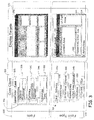
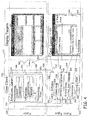
- FIGS. 3 and 4 shown are diagrammatic illustrations of a Sales Order logical form created using a Card form type in accordance with an example embodiment of the present invention.
- the Sales Order logical form contains a set of logical controls grouped into three different logical control groups.
- the Card form type defines how and where the controls will appear on the physical form and on different display targets, and which physical controls to use for rendering.
- FIGS. 3 and 4 illustrate the same information, with FIG. 4 including arrows illustrating relationships and origins of information between the logical form type and the logical form, and the generation of a physical form from the logical form.
- FIGS. 3 and 4 diagrammatically illustrate a form instance 305 generated using a form type 300.
- a core client 310 which is a display target independent forms engine
- form instance 305 is logical form 306 (shown as a conceptual model of a form) and form type 300 is a logical form type 301.
- a display target 320 form 305 is a rendered form 370 created using logical form 306, and ultimately from logical form type 301.
- Rendered form 370 is one particular implementation, but many other implementations or renderings can be achieved.
- the rendered form 370 can also be referred to as a physical form.
- Two parts included in form type 300 include a schema 330 that defines what has to be included in particular forms using the form type, and a layout 331 that includes controls which specify how the form should be rendered or drawn on a specific display target.
- the form type also contains a mapping from logical to physical controls, which can also be considered to be part of the layout 331 in some embodiments.
- the form type may also include logic determining the interaction between UI elements (controls, etc.). This logic is display target independent, so the schema also includes "code-behind".
- the forms created using the form type can be tailored to different display targets (e.g., cell phone displays, personal digital assistant displays, personal computer monitors, etc.).
- form type 300 representing a captured pattern to be used in multiple forms, multiple form instances 305 can be generated using form type 300.
- the form types can include a pattern for navigating between forms - the form type defines how another form (of a given type) is opened - e.g. in its own window or replacing the content area.
- the logical form 306 will include a Content Area 336 corresponding to Content Area 335 defined in the schema 330.
- the origin of Content Area 336 corresponding to Content Area 335 is represented by arrow 337 in FIG. 4.
- the logical form 306 includes these areas or fields as well as shown at 341, 346 and 351. Again, the origins of these fields are represented diagrammatically by arrows 342, 347 and 352.
- each form type also includes a layout 331 that dictates which controls to use for rendering on a specific display target.
- the layout for the card form type includes controls which cause a display target 320 to include a Content Area 339, a UI Part Area 344, a Related Entity IU Part Area 349, and an Action Area 354.
- Arrows 338, 343, 348 and 353 illustrate the correlation of these areas in the card layout to their corresponding areas in the Card schema.
- a flow diagram 500 which illustrates a method of generating a model driven form user interface to represent a data model as was described above with reference to FIGS. 3 and 4.
- the method is shown to include selecting which of multiple different logical form types to use to generate the form user interface to represent the data model.
- a Card or CardView form type was selected for this purpose.
- the method includes generating a logical form at run-time using the data model and the selected logical form type.
- the data model is preserved (i.e., acted on at run-time), and any changes made to the data model will be reflected in the logical form and in the rendered physical form.
- the step 510 can be considered to include generating the logical form at run-time using both the selected logical form type model and meta data from the data model.
- each of the multiple different logical form types has an associated schema which defines data from the data model to be included in the generated logical form. Therefore, the step 510 of generating the logical form at run-time includes generating the logical form using the associated schema in exemplary embodiments. Since the schema of each of the different logical form types represents patterns captured from a large number of forms, a few form types can be used to generate a very large number of forms. Also, since each of the logical form types has at least one defined layout which is specific to a particular display target, a step of generating a physical form at run-time includes generating the physical form using the at least one defined layout. In other embodiments, each logical form type can include multiple different layouts corresponding to multiple different display targets to facilitate generation of a large number of forms for the different display targets.
- the methods disclosed herein generate multiple different form user interfaces to represent a single data model.
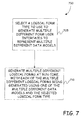
- the method is shown to further include the step 605 of selecting multiple different logical form types to use to generate the multiple different form user interfaces to represent the data model.
- the method includes generating the multiple different logical forms at run-time, with each of the different logical forms being generated using the data model and a different one of the selected logical form types.
- the data model is acted upon at run-time, this allows changes to the data model to be implemented in multiple generated forms automatically. Altering the data model a single time, but automatically affecting multiple forms at run-time provides a significant increase in efficiency as compared to conventional more labor intensive methods of generating forms.
- the methods of the present invention are used to generate multiple different model driven form user interfaces to represent multiple different data models.
- this more particular embodiment of the method includes selecting which one of multiple different logical form types to use to generate multiple different form user interfaces to represent the data models.
- the method is shown to include generating multiple different logical forms at run-time, with each of the multiple different logical forms being generated using one of the multiple different data models and the selected logical form type.
- a single form type can be used to generate a logical form for each of a large number of data models.
- each of the multiple different form user interfaces can be altered by altering the one selected logical form type a single time.
- system 800 includes processing/control component 810 and data stores 820 and 840 for storing meta data related to either the data models 815 (for example business models in the form of entities or objects) or for storing form types 825 and associated schemas 830 and layouts 835.
- Developer inputs 805 can be, but is not restricted to, any inputs which select form types and data models to be used to generate logical forms 845.
- Example input actions can include selecting, from a list or otherwise, which form type to use.
- the developer inputs can also include input actions such as dragging a visual representation of the data model onto a visual representation of the selected form type in order to dictate which field types the generated logical form should include. Many other developer inputs can also be used.
- Logical form types can also be used by third parties to customize the form types at runtime, which is not necessarily considered to be selecting data models or form types. Therefore, developer input is not necessarily restricted to "design time”. Further, the methods of the present invention are not restricted to embodiments requiring developer input. In other embodiments, the form types can be personalized - allowing the end user to change multiple forms at once.
- processing/control component 810 is configured to generate logical forms 845 as described above. Then, a rendering engine 850 generates the physical forms 855 and the corresponding display target(s) 860.
Landscapes
- Engineering & Computer Science (AREA)
- Software Systems (AREA)
- General Engineering & Computer Science (AREA)
- Theoretical Computer Science (AREA)
- Health & Medical Sciences (AREA)
- Physics & Mathematics (AREA)
- General Physics & Mathematics (AREA)
- Human Computer Interaction (AREA)
- General Health & Medical Sciences (AREA)
- Otolaryngology (AREA)
- Pulmonology (AREA)
- Orthopedic Medicine & Surgery (AREA)
- Nursing (AREA)
- Biomedical Technology (AREA)
- Heart & Thoracic Surgery (AREA)
- Vascular Medicine (AREA)
- Life Sciences & Earth Sciences (AREA)
- Animal Behavior & Ethology (AREA)
- Public Health (AREA)
- Veterinary Medicine (AREA)
- Management, Administration, Business Operations System, And Electronic Commerce (AREA)
- User Interface Of Digital Computer (AREA)
- Digital Computer Display Output (AREA)
- Stored Programmes (AREA)
Applications Claiming Priority (2)
| Application Number | Priority Date | Filing Date | Title |
|---|---|---|---|
| US860226 | 2004-06-03 | ||
| US10/860,226 US7665014B2 (en) | 2004-06-03 | 2004-06-03 | Method and apparatus for generating forms using form types |
Publications (2)
| Publication Number | Publication Date |
|---|---|
| EP1603033A2 true EP1603033A2 (de) | 2005-12-07 |
| EP1603033A3 EP1603033A3 (de) | 2007-12-12 |
Family
ID=34940046
Family Applications (1)
| Application Number | Title | Priority Date | Filing Date |
|---|---|---|---|
| EP05104721A Ceased EP1603033A3 (de) | 2004-06-03 | 2005-06-01 | Verfahren und Vorrichtung zum Generieren von Formularen unter Verwendung von Formulartypen |
Country Status (5)
| Country | Link |
|---|---|
| US (1) | US7665014B2 (de) |
| EP (1) | EP1603033A3 (de) |
| JP (1) | JP4812337B2 (de) |
| KR (1) | KR101130525B1 (de) |
| CN (1) | CN100580667C (de) |
Cited By (1)
| Publication number | Priority date | Publication date | Assignee | Title |
|---|---|---|---|---|
| CN101847099A (zh) * | 2010-06-08 | 2010-09-29 | 用友软件股份有限公司 | 个性化配置应用功能的方法和装置 |
Families Citing this family (24)
| Publication number | Priority date | Publication date | Assignee | Title |
|---|---|---|---|---|
| US8850304B2 (en) * | 2010-02-05 | 2014-09-30 | Kip Medv Pi Lp | System and method for visually mapping and automatically completing electronic forms |
| US20060026522A1 (en) * | 2004-07-27 | 2006-02-02 | Microsoft Corporation | Method and apparatus for revising data models and maps by example |
| US20070156977A1 (en) * | 2005-12-29 | 2007-07-05 | Ritter Gerd M | Automatic location data determination in an electronic document |
| US7730412B2 (en) * | 2006-06-30 | 2010-06-01 | Sap Ag | System and method for model-based user interface using transformation nodes |
| US8683315B2 (en) * | 2006-11-06 | 2014-03-25 | Eci Software, Inc. | System and method for creating integrated web form and database applications |
| US8484663B2 (en) * | 2007-04-27 | 2013-07-09 | Microsoft Corporation | Method of deriving web service interfaces from form and table metadata |
| US8543903B2 (en) * | 2008-01-14 | 2013-09-24 | International Business Machines Corporation | System and method of integrating a plurality of form related workflow tools |
| US8209355B2 (en) * | 2008-07-28 | 2012-06-26 | Microsoft Corporation | Automatic user interface generation for entity interaction |
| US20110035655A1 (en) * | 2009-08-04 | 2011-02-10 | Sap Ag | Generating Forms Using One or More Transformation Rules |
| CN101706720B (zh) * | 2009-11-23 | 2013-07-24 | 浪潮集团山东通用软件有限公司 | 一种运行时根据用户自定义信息进行界面展示方法 |
| US20110185294A1 (en) * | 2010-01-22 | 2011-07-28 | Microsoft Corporation | Pattern-based user interfaces |
| CA2783451C (en) | 2010-06-03 | 2018-01-16 | International Business Machines Corporation | Method and system of adapting a data model to a user interface component |
| CN102789382B (zh) * | 2012-06-28 | 2015-09-23 | 用友软件股份有限公司 | 用于表单生成和运行的系统及方法 |
| US9223760B2 (en) | 2012-07-13 | 2015-12-29 | International Business Machines Corporation | Method of encapsulating diverse user interface components while consistently enforcing external constraints |
| US20140149470A1 (en) * | 2012-11-27 | 2014-05-29 | Sandeep Rawal | Systems and methods for storing and populating forms |
| US10296562B2 (en) | 2013-02-12 | 2019-05-21 | Oath Inc. | Dynamic generation of mobile web experience |
| EP2767901B1 (de) | 2013-02-19 | 2020-05-20 | Quadient Group AG | Erzeugung interaktiver elektronischer Dokumente |
| RU2536391C1 (ru) * | 2013-04-26 | 2014-12-20 | Общество с ограниченной ответственностью "1С" | Способ автоматизированного изменения интерфейса (варианты) |
| CN103713901B (zh) * | 2013-12-24 | 2018-01-12 | 金蝶软件(中国)有限公司 | 单据的展示方法和系统 |
| US9736032B2 (en) | 2014-05-30 | 2017-08-15 | Microsoft Technology Licensing, Llc | Pattern-based validation, constraint and generation of hierarchical metadata |
| RU2015116133A (ru) * | 2015-04-29 | 2016-11-20 | Общество с ограниченной ответственностью "1С" | Способ автоматизированного генерирования интерфейса приложения |
| KR101916802B1 (ko) * | 2017-08-17 | 2019-01-25 | (주) 더존비즈온 | 블록 ui를 이용한 양식 생성 장치 및 방법 |
| CN110442340B (zh) * | 2019-07-04 | 2023-10-10 | 湖南善禧文化股份有限公司 | 基于数据处理的表单生成方法、装置和计算机设备 |
| CN114047855B (zh) * | 2021-11-18 | 2023-11-07 | 北京字跳网络技术有限公司 | 一种表单编辑方法、装置及终端设备 |
Citations (4)
| Publication number | Priority date | Publication date | Assignee | Title |
|---|---|---|---|---|
| US6429882B1 (en) | 1999-03-15 | 2002-08-06 | Sun Microsystems, Inc. | User interface component |
| US20030025732A1 (en) | 2001-07-31 | 2003-02-06 | Prichard Scot D. | Method and apparatus for providing customizable graphical user interface and screen layout |
| US20040027378A1 (en) * | 2002-08-06 | 2004-02-12 | Hays Grace L. | Creation of user interfaces for multiple devices |
| US20040083426A1 (en) | 2002-10-25 | 2004-04-29 | Smita Sahu | System and method for generating pre-populated forms |
Family Cites Families (36)
| Publication number | Priority date | Publication date | Assignee | Title |
|---|---|---|---|---|
| US5649190A (en) * | 1994-06-14 | 1997-07-15 | Harris Corporation | Multi-model database system for dynamic creation and maintenance of complex objects in a real time environment |
| US6076051A (en) * | 1997-03-07 | 2000-06-13 | Microsoft Corporation | Information retrieval utilizing semantic representation of text |
| US5999948A (en) * | 1997-09-03 | 1999-12-07 | 3Com Corporation | Dynamic configuration forms in network management software |
| US6012098A (en) * | 1998-02-23 | 2000-01-04 | International Business Machines Corp. | Servlet pairing for isolation of the retrieval and rendering of data |
| CA2363733C (en) * | 1999-03-02 | 2011-10-18 | Quixtar Investments, Inc. | Electronic commerce transactions within a marketing system |
| US6456740B1 (en) * | 1999-07-26 | 2002-09-24 | International Business Machines Corporation | System and method for identifying form type in a handwriting recognition based form completion system |
| US6636242B2 (en) * | 1999-08-31 | 2003-10-21 | Accenture Llp | View configurer in a presentation services patterns environment |
| US6704743B1 (en) * | 1999-09-13 | 2004-03-09 | Copernus, Inc. | Selective inheritance of object parameters in object-oriented computer environment |
| US20030221162A1 (en) * | 2000-03-20 | 2003-11-27 | Sridhar Mandayam Andampillai | Meta-templates in website development and methods therefor |
| US6580440B1 (en) * | 2000-04-05 | 2003-06-17 | Ncr Corporation | System and method for automatically creating and updating a graphical user interface |
| US6968500B2 (en) * | 2000-04-05 | 2005-11-22 | Dmitry Mikhailov | Automatic forms handling system |
| WO2001088661A2 (en) * | 2000-05-16 | 2001-11-22 | U.S. Army Medical Research And Material Command | System and method for providing access to forms and maintaining the data used to complete the forms |
| ES2355188T3 (es) * | 2000-06-23 | 2011-03-23 | Sportvision Inc. | Sistema para seguir la trayectoria basado en gps. |
| US20020083068A1 (en) * | 2000-10-30 | 2002-06-27 | Quass Dallan W. | Method and apparatus for filling out electronic forms |
| WO2002041624A2 (en) * | 2000-11-06 | 2002-05-23 | Terry Bernard Young | Electronic markets business interchange system and metheo |
| US7194743B2 (en) * | 2000-12-12 | 2007-03-20 | Citrix Systems, Inc. | Methods and apparatus for communicating changes between a user interface and an executing application using property paths |
| US20020091732A1 (en) * | 2000-12-29 | 2002-07-11 | Pedro Justin E. | Displaying forms and content in a browser |
| US7194683B2 (en) * | 2001-03-02 | 2007-03-20 | International Business Machines Corporation | Representing and managing dynamic data content for web documents |
| US20030131142A1 (en) * | 2001-03-14 | 2003-07-10 | Horvitz Eric J. | Schema-based information preference settings |
| US20040205525A1 (en) * | 2001-04-30 | 2004-10-14 | Murren Brian T. | Automatic identification of form contents |
| US20030135825A1 (en) * | 2001-12-05 | 2003-07-17 | Matthew Gertner | Dynamically generated mark-up based graphical user interfaced with an extensible application framework with links to enterprise resources |
| US7171615B2 (en) * | 2002-03-26 | 2007-01-30 | Aatrix Software, Inc. | Method and apparatus for creating and filing forms |
| US20040039990A1 (en) * | 2002-03-30 | 2004-02-26 | Xorbix Technologies, Inc. | Automated form and data analysis tool |
| US20030221165A1 (en) * | 2002-05-22 | 2003-11-27 | Microsoft Corporation | System and method for metadata-driven user interface |
| US7032170B2 (en) * | 2002-06-03 | 2006-04-18 | General Electric Company | Creating data structures from a form file and creating a web page in conjunction with corresponding data structures |
| US20050005259A1 (en) * | 2003-03-14 | 2005-01-06 | Infowave Software, Inc. | System and method for communication and mapping of business objects between mobile client devices and a plurality of backend systems |
| US7194106B2 (en) * | 2003-04-03 | 2007-03-20 | Digimarc Corporation | Creating electronic forms through digital watermarking |
| US20040237030A1 (en) * | 2003-05-19 | 2004-11-25 | Malkin Wayne Allan | System and method of implementing calculation fields in an electronic form |
| US8504380B2 (en) * | 2003-06-05 | 2013-08-06 | Medidata Solutions, Inc. | Assistance for clinical trial protocols |
| WO2004112301A2 (en) * | 2003-06-11 | 2004-12-23 | Wtviii, Inc. | Mark up language authoring system |
| US7698176B2 (en) * | 2003-07-28 | 2010-04-13 | At&T Intellectual Property I, L.P. | Method, system, and computer-readable medium for updating inventory data in an inventory management system |
| JP4089655B2 (ja) * | 2003-09-16 | 2008-05-28 | セイコーエプソン株式会社 | レイアウトシステムおよびレイアウトプログラム、並びにレイアウト方法 |
| US7933762B2 (en) * | 2004-04-16 | 2011-04-26 | Fortelligent, Inc. | Predictive model generation |
| US7424485B2 (en) * | 2004-06-03 | 2008-09-09 | Microsoft Corporation | Method and apparatus for generating user interfaces based upon automation with full flexibility |
| US20060026522A1 (en) * | 2004-07-27 | 2006-02-02 | Microsoft Corporation | Method and apparatus for revising data models and maps by example |
| US7584416B2 (en) * | 2006-02-21 | 2009-09-01 | Microsoft Corporation | Logical representation of a user interface form |
-
2004
- 2004-06-03 US US10/860,226 patent/US7665014B2/en not_active Expired - Fee Related
-
2005
- 2005-04-21 KR KR1020050033059A patent/KR101130525B1/ko not_active Expired - Fee Related
- 2005-05-12 CN CN200510071283A patent/CN100580667C/zh not_active Expired - Fee Related
- 2005-06-01 EP EP05104721A patent/EP1603033A3/de not_active Ceased
- 2005-06-03 JP JP2005164519A patent/JP4812337B2/ja not_active Expired - Fee Related
Patent Citations (4)
| Publication number | Priority date | Publication date | Assignee | Title |
|---|---|---|---|---|
| US6429882B1 (en) | 1999-03-15 | 2002-08-06 | Sun Microsystems, Inc. | User interface component |
| US20030025732A1 (en) | 2001-07-31 | 2003-02-06 | Prichard Scot D. | Method and apparatus for providing customizable graphical user interface and screen layout |
| US20040027378A1 (en) * | 2002-08-06 | 2004-02-12 | Hays Grace L. | Creation of user interfaces for multiple devices |
| US20040083426A1 (en) | 2002-10-25 | 2004-04-29 | Smita Sahu | System and method for generating pre-populated forms |
Cited By (1)
| Publication number | Priority date | Publication date | Assignee | Title |
|---|---|---|---|---|
| CN101847099A (zh) * | 2010-06-08 | 2010-09-29 | 用友软件股份有限公司 | 个性化配置应用功能的方法和装置 |
Also Published As
| Publication number | Publication date |
|---|---|
| US20060036634A1 (en) | 2006-02-16 |
| JP2005346722A (ja) | 2005-12-15 |
| CN100580667C (zh) | 2010-01-13 |
| US7665014B2 (en) | 2010-02-16 |
| KR101130525B1 (ko) | 2012-03-28 |
| KR20060047321A (ko) | 2006-05-18 |
| JP4812337B2 (ja) | 2011-11-09 |
| CN1704937A (zh) | 2005-12-07 |
| EP1603033A3 (de) | 2007-12-12 |
Similar Documents
| Publication | Publication Date | Title |
|---|---|---|
| US7665014B2 (en) | Method and apparatus for generating forms using form types | |
| US7424485B2 (en) | Method and apparatus for generating user interfaces based upon automation with full flexibility | |
| US7809597B2 (en) | Progressive refinement model for business processes | |
| US8433602B2 (en) | Modeling of business process data | |
| US10019239B2 (en) | Systems and methods for enhancing software products through integrated development environment running on host computer | |
| US8712953B2 (en) | Data consumption framework for semantic objects | |
| US9286037B2 (en) | Platform for distributed applications | |
| CN102982396B (zh) | 通用过程建模框架 | |
| CN102221993B (zh) | 复杂用户界面状态变更的声明性定义 | |
| JP5460941B2 (ja) | ソフトウェアシステムのための拡張可能なカスタマイズフレームワークおよび方法 | |
| US7363578B2 (en) | Method and apparatus for mapping a data model to a user interface model | |
| US8423477B2 (en) | Providing multiple views of a business process definition to different classes of users | |
| US7603624B2 (en) | System and method for styling content in a graphical user interface control | |
| JP2004280829A (ja) | コンピューティング環境においてオブジェクトを記述するメタデータのカスタマイズ | |
| JP2004280814A (ja) | ソフトウェアシステム内での処理ロジックのカスタマイズ方法 | |
| JP2013518321A (ja) | パターンベースのユーザインターフェース | |
| US20060259386A1 (en) | Building digital assets for use with software applications | |
| JP2004272911A (ja) | コンピューティング環境におけるオブジェクト内のフィールドのカスタマイズ | |
| Schattkowsky et al. | Uml model mappings for platform independent user interface design | |
| Horvath | Collaborative Spaces for Increased Traceability in Knowledge-Intensive Document-Based Processes |
Legal Events
| Date | Code | Title | Description |
|---|---|---|---|
| PUAI | Public reference made under article 153(3) epc to a published international application that has entered the european phase |
Free format text: ORIGINAL CODE: 0009012 |
|
| AK | Designated contracting states |
Kind code of ref document: A2 Designated state(s): AT BE BG CH CY CZ DE DK EE ES FI FR GB GR HU IE IS IT LI LT LU MC NL PL PT RO SE SI SK TR |
|
| AX | Request for extension of the european patent |
Extension state: AL BA HR LV MK YU |
|
| PUAL | Search report despatched |
Free format text: ORIGINAL CODE: 0009013 |
|
| AK | Designated contracting states |
Kind code of ref document: A3 Designated state(s): AT BE BG CH CY CZ DE DK EE ES FI FR GB GR HU IE IS IT LI LT LU MC NL PL PT RO SE SI SK TR |
|
| AX | Request for extension of the european patent |
Extension state: AL BA HR LV MK YU |
|
| 17P | Request for examination filed |
Effective date: 20080104 |
|
| AKX | Designation fees paid |
Designated state(s): AT BE BG CH CY CZ DE DK EE ES FI FR GB GR HU IE IS IT LI LT LU MC NL PL PT RO SE SI SK TR |
|
| 17Q | First examination report despatched |
Effective date: 20091013 |
|
| RAP1 | Party data changed (applicant data changed or rights of an application transferred) |
Owner name: MICROSOFT TECHNOLOGY LICENSING, LLC |
|
| APBK | Appeal reference recorded |
Free format text: ORIGINAL CODE: EPIDOSNREFNE |
|
| APBN | Date of receipt of notice of appeal recorded |
Free format text: ORIGINAL CODE: EPIDOSNNOA2E |
|
| APBR | Date of receipt of statement of grounds of appeal recorded |
Free format text: ORIGINAL CODE: EPIDOSNNOA3E |
|
| APAF | Appeal reference modified |
Free format text: ORIGINAL CODE: EPIDOSCREFNE |
|
| APBT | Appeal procedure closed |
Free format text: ORIGINAL CODE: EPIDOSNNOA9E |
|
| STAA | Information on the status of an ep patent application or granted ep patent |
Free format text: STATUS: THE APPLICATION HAS BEEN REFUSED |
|
| 18R | Application refused |
Effective date: 20200416 |