EP1602879A2 - Headlamp for vehicles with a shielding housing for the ballast unit of the discharge lamp - Google Patents
Headlamp for vehicles with a shielding housing for the ballast unit of the discharge lamp Download PDFInfo
- Publication number
- EP1602879A2 EP1602879A2 EP05104803A EP05104803A EP1602879A2 EP 1602879 A2 EP1602879 A2 EP 1602879A2 EP 05104803 A EP05104803 A EP 05104803A EP 05104803 A EP05104803 A EP 05104803A EP 1602879 A2 EP1602879 A2 EP 1602879A2
- Authority
- EP
- European Patent Office
- Prior art keywords
- housing
- discharge lamp
- electronic circuit
- contact pin
- headlamp
- Prior art date
- Legal status (The legal status is an assumption and is not a legal conclusion. Google has not performed a legal analysis and makes no representation as to the accuracy of the status listed.)
- Granted
Links
Images

Classifications
-
- F—MECHANICAL ENGINEERING; LIGHTING; HEATING; WEAPONS; BLASTING
- F21—LIGHTING
- F21V—FUNCTIONAL FEATURES OR DETAILS OF LIGHTING DEVICES OR SYSTEMS THEREOF; STRUCTURAL COMBINATIONS OF LIGHTING DEVICES WITH OTHER ARTICLES, NOT OTHERWISE PROVIDED FOR
- F21V25/00—Safety devices structurally associated with lighting devices
-
- B—PERFORMING OPERATIONS; TRANSPORTING
- B60—VEHICLES IN GENERAL
- B60Q—ARRANGEMENT OF SIGNALLING OR LIGHTING DEVICES, THE MOUNTING OR SUPPORTING THEREOF OR CIRCUITS THEREFOR, FOR VEHICLES IN GENERAL
- B60Q1/00—Arrangement of optical signalling or lighting devices, the mounting or supporting thereof or circuits therefor
- B60Q1/0088—Details of electrical connections
- B60Q1/0094—Arrangement of electronic circuits separated from the light source, e.g. mounting of housings for starter circuits for discharge lamps
-
- F—MECHANICAL ENGINEERING; LIGHTING; HEATING; WEAPONS; BLASTING
- F21—LIGHTING
- F21S—NON-PORTABLE LIGHTING DEVICES; SYSTEMS THEREOF; VEHICLE LIGHTING DEVICES SPECIALLY ADAPTED FOR VEHICLE EXTERIORS
- F21S41/00—Illuminating devices specially adapted for vehicle exteriors, e.g. headlamps
- F21S41/10—Illuminating devices specially adapted for vehicle exteriors, e.g. headlamps characterised by the light source
- F21S41/14—Illuminating devices specially adapted for vehicle exteriors, e.g. headlamps characterised by the light source characterised by the type of light source
- F21S41/17—Discharge light sources
-
- F—MECHANICAL ENGINEERING; LIGHTING; HEATING; WEAPONS; BLASTING
- F21—LIGHTING
- F21S—NON-PORTABLE LIGHTING DEVICES; SYSTEMS THEREOF; VEHICLE LIGHTING DEVICES SPECIALLY ADAPTED FOR VEHICLE EXTERIORS
- F21S41/00—Illuminating devices specially adapted for vehicle exteriors, e.g. headlamps
- F21S41/10—Illuminating devices specially adapted for vehicle exteriors, e.g. headlamps characterised by the light source
- F21S41/19—Attachment of light sources or lamp holders
- F21S41/192—Details of lamp holders, terminals or connectors
-
- F—MECHANICAL ENGINEERING; LIGHTING; HEATING; WEAPONS; BLASTING
- F21—LIGHTING
- F21S—NON-PORTABLE LIGHTING DEVICES; SYSTEMS THEREOF; VEHICLE LIGHTING DEVICES SPECIALLY ADAPTED FOR VEHICLE EXTERIORS
- F21S41/00—Illuminating devices specially adapted for vehicle exteriors, e.g. headlamps
- F21S41/50—Illuminating devices specially adapted for vehicle exteriors, e.g. headlamps characterised by aesthetic components not otherwise provided for, e.g. decorative trim, partition walls or covers
- F21S41/55—Attachment thereof
-
- H—ELECTRICITY
- H01—ELECTRIC ELEMENTS
- H01R—ELECTRICALLY-CONDUCTIVE CONNECTIONS; STRUCTURAL ASSOCIATIONS OF A PLURALITY OF MUTUALLY-INSULATED ELECTRICAL CONNECTING ELEMENTS; COUPLING DEVICES; CURRENT COLLECTORS
- H01R4/00—Electrically-conductive connections between two or more conductive members in direct contact, i.e. touching one another; Means for effecting or maintaining such contact; Electrically-conductive connections having two or more spaced connecting locations for conductors and using contact members penetrating insulation
- H01R4/58—Electrically-conductive connections between two or more conductive members in direct contact, i.e. touching one another; Means for effecting or maintaining such contact; Electrically-conductive connections having two or more spaced connecting locations for conductors and using contact members penetrating insulation characterised by the form or material of the contacting members
- H01R4/64—Connections between or with conductive parts having primarily a non-electric function, e.g. frame, casing, rail
Definitions
- the invention relates to a headlamp for vehicles with a gas discharge lamp, with a reflector having a reflector opening for receiving the Gas discharge lamp, with a ballast for operating the gas discharge lamp containing a shielded housing for shielding of electromagnetic interference in which an electronic circuit is arranged, that contact means are provided for contacting the Housing on a ground connection.
- headlights have been known for vehicles as light source have a gas discharge lamp.
- a gas discharge lamp For generating a relatively high ignition voltage for the gas discharge lamp an electronic circuit is required, the DC power provided by the electrical system in a Alternating current of predetermined height and frequency transforms.
- the electronic Circuit is housed in a ballast, the usual way has a shielded housing.
- a housing 1 made of a metal material and an electronic Completely enclose circuit 2 for operating the gas discharge lamp.
- a ground contact pin 3 and another Pin 4 off for electrical power supply of the electronic circuit 2 protrude one side of the housing 1 on the one hand a ground contact pin 3 and another Pin 4 off, with the ground contact pin 3 with the negative pole and the further contact pin 4 is connected to the positive pole of the vehicle electrical system.
- the Contact pins 3, 4 are facing one of the electronic circuit Side electrically conductive connected to corresponding tracks of the same. Opposite a wall of the housing 1 they are by means of openings the wall of the housing bordered sleeves disposed electrically insulating. To minimize the electromagnetic interference is the housing 1 via an electrically conductive connected to the same pin 5 with connectable to a ground terminal of the vehicle.
- grounding of the housing according to Figure 2 may be an electrical connection between tracks of the electronic Circuit 2 and the inside of the housing 1 instead of an additional Ground contact pin produced within the housing 1 by means of bonding become.
- Object of the present invention is therefore to provide a headlight for vehicles with a ballast for operating a gas discharge lamp in such a way that the effort for grounding a housing the ballast is further reduced.
- the invention is in connection with the preamble of claim 1, characterized in that the contact means on a leading out of the housing ground terminal of the electronic Circuit is arranged.
- the particular advantage of the invention results from the fact that a ground connection element the electronic circuit of a ballast in addition used as ground contact means for the housing of the ballast becomes.
- the ground terminal element of the electrical circuit formed such that an electrically conductive connection of the same not only to the electronic circuit, but also to a wall of the housing.
- the connected to the negative pole of the electrical system Ground connection element of the ballast thus comes a double function to.
- This can advantageously be a relatively short ground connection of the Housing to be made to a ground connection. Additional contact means - As described in the prior art above - are not required.
- the ground terminal element of Vorschalt raised formed as a ground contact pin in the area a wall opening of the housing has a widening portion.
- the broadening section is shaped such that the ground contact pin positive and / or non-positive in the wall opening of the housing is held.
- the broadening section resilient outer sections have on a circumferential wall of the wall opening of the Housing abut.
- An inventive Vorschalt driving 20 for operating a not shown Gas discharge lamp of a headlamp can be a cuboid Have housing 21 made of a metal material.
- the ballast 20 has an electronic Circuit 22, the electronic components 23 on a common carrier plate 24 are housed.
- the support plate 24 is over as screws trained fastener 25 frictionally with a base wall 26th of the housing 21 or with an adjoining the same housing wall connected to the headlamp.
- the ballast 20 can immediately be attached to the housing of the headlamp, in addition to the gas discharge lamp in the usual way a reflector and a clear cover has in the light exit direction.
- a grounding element / ground contact pin 27 for electromagnetic shielding of the housing 21 is the same from a Metal material, such as aluminum produced.
- the ground contact pin 27 has is in the region of an opening of the base wall 26 a widening section 28, by means of which he at the Base wall 26 and the support plate 24 positive and / or non-positive is held.
- the widening portion 28 resilient outer sections (Outer surface), by means of which he in the opening under System clamped to a circumferential wall of the opening of the base wall 26 is arranged. This is a direct electrically conductive connection between the ground contact pin 27 and the base wall 26 given.
- a subsequent to the widening section 28, essentially outside of the housing 21 extending tongue-shaped outer portion 32 has the same shape as a corresponding outer portion a neighboring further contact pin 30, which serves as a connection of the electrical Circuit 22 is used at a positive pole of the electrical system.
- the contact pins 27, 30 can not be used for contacting, for example connected plugs are connected.
- the further contact pin 30 in contrast to the ground contact pin 27 is the further contact pin 30 by means of a within a Opening the base wall 26 extending electrically non-conductive Sleeve 31 bordered, wherein only one of the electronic circuit 22 facing End of the contact pin 30 electrically conductive with not shown Conductor tracks of the electronic circuit 22 is connected.
- the contact pins 27, 30 extend substantially parallel through adjacent ones Openings of the base wall 26 and have substantially the same length up.
- the contact pins 27, 30 are made of a metal material.
- the ballast 20 may according to an alternative embodiment also be formed in two parts, wherein an ignition unit for generating the required ignition voltage of the gas discharge lamp and one of the ignition unit serve upstream control unit for generating an operating current.
- the ignition unit can be arranged, for example, on a rear side of a reflector be.
Abstract
Description
Die Erfindung betrifft einen Scheinwerfer für Fahrzeuge mit einer Gasentladungslampe, mit einem Reflektor, der eine Reflektoröffnung zur Aufnahme der Gasentladungslampe aufweist, mit einer Vorschalteinrichtung zum Betreiben der Gasentladungslampe enthaltend ein abgeschirmtes Gehäuse zur Abschirmung von elektromagnetischer Störstrahlung, in dem eine elektronische Schaltung angeordnet ist, dass Kontaktmittel vorgesehen sind zur Kontaktierung des Gehäuses an einem Masseanschluss.The invention relates to a headlamp for vehicles with a gas discharge lamp, with a reflector having a reflector opening for receiving the Gas discharge lamp, with a ballast for operating the gas discharge lamp containing a shielded housing for shielding of electromagnetic interference in which an electronic circuit is arranged, that contact means are provided for contacting the Housing on a ground connection.
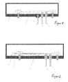
Seit einiger Zeit sind Scheinwerfer für Fahrzeuge bekannt, die als Lichtquelle eine Gasentladungslampe aufweisen. Zur Erzeugung einer relativ hohen Zündspannung für die Gasentladungslampe ist eine elektronische Schaltung erforderlich, die den vom Bordnetz zur Verfügung gestellten Gleichstrom in einen Wechselstrom vorgegebener Höhe und Frequenz umformt. Die elektronische Schaltung ist in einer Vorschalteinrichtung untergebracht, die üblicher Weise über ein abgeschirmtes Gehäuse verfügt. Wie aus Figur 1 zu ersehen ist, kann ein Gehäuse 1 aus einem Metallmaterial bestehen und eine elektronische Schaltung 2 zum Betreiben der Gasentladungslampe vollständig umschließen. Zur elektrischen Stromversorgung der elektronischen Schaltung 2 ragen auf einer Seite des Gehäuses 1 zum einen ein Masse-Kontaktstift 3 sowie ein weiterer Kontaktstift 4 ab, wobei der Masse-Kontaktstift 3 mit dem Minuspol und der weitere Kontaktstift 4 mit dem Pluspol des Bordnetzes verbunden ist. Die Kontaktstifte 3, 4 sind auf einer der elektronischen Schaltung zugewandten Seite mit entsprechenden Leiterbahnen derselben elektrisch leitend verbunden. Gegenüber einer Wandung des Gehäuses 1 sind sie mittels in Öffnungen der Wandung des Gehäuses eingefasster Hülsen elektrisch isolierend angeordnet. Zur Minimierung der elektromagnetischen Störstrahlung ist das Gehäuse 1 über ein elektrisch leitend mit demselben verbundenen Kontaktstift 5 mit einem Masseanschluss des Fahrzeugs verbindbar. For some time, headlights have been known for vehicles as light source have a gas discharge lamp. For generating a relatively high ignition voltage for the gas discharge lamp an electronic circuit is required, the DC power provided by the electrical system in a Alternating current of predetermined height and frequency transforms. The electronic Circuit is housed in a ballast, the usual way has a shielded housing. As can be seen from Figure 1, can a housing 1 made of a metal material and an electronic Completely enclose circuit 2 for operating the gas discharge lamp. For electrical power supply of the electronic circuit 2 protrude one side of the housing 1 on the one hand a ground contact pin 3 and another Pin 4 off, with the ground contact pin 3 with the negative pole and the further contact pin 4 is connected to the positive pole of the vehicle electrical system. The Contact pins 3, 4 are facing one of the electronic circuit Side electrically conductive connected to corresponding tracks of the same. Opposite a wall of the housing 1 they are by means of openings the wall of the housing bordered sleeves disposed electrically insulating. To minimize the electromagnetic interference is the housing 1 via an electrically conductive connected to the same pin 5 with connectable to a ground terminal of the vehicle.
Nach einer alternativen bekannten Massekontaktierung des Gehäuses gemäß Figur 2 kann eine elektrische Verbindung zwischen Leiterbahnen der elektronischen Schaltung 2 und der Innenseite des Gehäuses 1 anstatt eines zusätzliches Massekontaktstiftes innerhalb des Gehäuses 1 mittels Bonden hergestellt werden.According to an alternative known grounding of the housing according to Figure 2 may be an electrical connection between tracks of the electronic Circuit 2 and the inside of the housing 1 instead of an additional Ground contact pin produced within the housing 1 by means of bonding become.
Mit dem Vorsehen von zusätzlichen Kontaktmitteln 5, 6 ist die Massekontaktierung des Gehäuses 1 jedoch relativ aufwändig.With the provision of additional contact means 5, 6 is the ground contact of the housing 1, however, relatively expensive.
Aufgabe der vorliegenden Erfindung ist es daher, einen Scheinwerfer für Fahrzeuge mit einer Vorschalteinrichtung zum Betreiben einer Gasentladungslampe derart weiterzubilden, dass der Aufwand zur Massekontaktierung eines Gehäuses der Vorschalteinrichtung weiter reduziert wird.Object of the present invention is therefore to provide a headlight for vehicles with a ballast for operating a gas discharge lamp in such a way that the effort for grounding a housing the ballast is further reduced.
Zur Lösung dieser Aufgabe ist die Erfindung in Verbindung mit dem Oberbegriff des Patenanspruchs 1 dadurch gekennzeichnet, dass das Kontaktmittel an einem aus dem Gehäuse herausführenden Masseanschlusselement der elektronischen Schaltung angeordnet ist.To solve this problem, the invention is in connection with the preamble of claim 1, characterized in that the contact means on a leading out of the housing ground terminal of the electronic Circuit is arranged.
Der besondere Vorteil der Erfindung ergibt sich daraus, dass ein Masseanschlusselement der elektronischen Schaltung einer Vorschalteinrichtung zusätzlich als Massekontaktmittel für das Gehäuse der Vorschalteinrichtung eingesetzt wird. Hierzu ist das Masseanschlusselement der elektrischen Schaltung derart ausgebildet, dass eine elektrisch leitende Verbindung von demselben nicht nur zur elektronischen Schaltung, sondern auch zu einer Wandung des Gehäuses besteht. Dem mit dem Minuspol des Bordnetzes verbundenen Masseanschlusselement der Vorschalteinrichtung kommt somit eine Doppelfunktion zu. Vorteilhaft kann hierdurch eine relativ kurze Masseanbindung des Gehäuses an einen Masseanschluss hergestellt werden. Zusätzliche Kontaktmittel - wie beim Stand der Technik oben beschrieben - sind nicht erforderlich. The particular advantage of the invention results from the fact that a ground connection element the electronic circuit of a ballast in addition used as ground contact means for the housing of the ballast becomes. For this purpose, the ground terminal element of the electrical circuit formed such that an electrically conductive connection of the same not only to the electronic circuit, but also to a wall of the housing. The connected to the negative pole of the electrical system Ground connection element of the ballast thus comes a double function to. This can advantageously be a relatively short ground connection of the Housing to be made to a ground connection. Additional contact means - As described in the prior art above - are not required.
Nach einer Weiterbildung der Erfindung ist das Masseanschlusselement der Vorschalteinrichtung als ein Masse-Kontaktstift ausgebildet, der im Bereich einer Wandungsöffnung des Gehäuses einen Verbreiterungsabschnitt aufweist. Der Verbreiterungsabschnitt ist derart geformt, dass der Masse-Kontaktstift form- und/oder kraftschlüssig in der Wandungsöffnung des Gehäuses gehalten ist. Hierzu kann der Verbreiterungsabschnitt federnde Außenabschnitte aufweisen, die an einer umlaufenden Wand der Wandungsöffnung des Gehäuses anliegen.According to a development of the invention, the ground terminal element of Vorschalteinrichtung formed as a ground contact pin in the area a wall opening of the housing has a widening portion. The broadening section is shaped such that the ground contact pin positive and / or non-positive in the wall opening of the housing is held. For this purpose, the broadening section resilient outer sections have on a circumferential wall of the wall opening of the Housing abut.
Weitere Vorteile der Erfindung ergeben sich aus den weiteren Unteransprüchen. Further advantages of the invention will become apparent from the further subclaims.
Ein Ausführungsbeispiel der Erfindung wird nachfolgend anhand der Zeichnungen näher erläutert.An embodiment of the invention will be described below with reference to the drawings explained in more detail.
Es zeigen:
- Figur 1
- einen schematischen Querschnitt durch eine Vorschalteinrichtung mit einer Masseanbindung für ein Gehäuse derselben nach einer ersten Variante des Standes der Technik,
- Figur 2
- einen schematischen Querschnitt durch eine Vorschalteinrichtung mit einer Masseanbindung für ein Gehäuse derselben nach einer zweiten Variante des Standes der Technik und
- Figur 3
- einen schematischen Querschnitt durch eine erfindungsgemäße Vorschalteinrichtung.
- FIG. 1
- 3 shows a schematic cross section through a ballast with a ground connection for a housing thereof according to a first variant of the prior art,
- FIG. 2
- a schematic cross section through a ballast with a ground connection for a housing thereof according to a second variant of the prior art and
- FIG. 3
- a schematic cross section through a ballast according to the invention.
Eine erfindungsgemäße Vorschalteinrichtung 20 zum Betreiben einer nicht dargestellten
Gasentladungslampe eines Scheinwerfers kann ein quaderförmiges
Gehäuse 21 aus einem Metallmaterial aufweisen. Zur Erzeugung einer relativ
hohen Zündspannung weist die Vorschalteinrichtung 20 eine elektronische
Schaltung 22 auf, deren elektronische Bauteile 23 auf einer gemeinsamen Trägerplatte
24 untergebracht sind. Die Trägerplatte 24 ist über als Schrauben
ausgebildete Befestigungsmittel 25 kraftschlüssig mit einer Basiswandung 26
des Gehäuses 21 bzw. mit einer an dieselbe anschließenden Gehäusewandung
des Scheinwerfers verbunden. Die Vorschalteinrichtung 20 kann unmittelbar
an dem Gehäuse des Scheinwerfers befestigt sein, der neben der Gasentladungslampe
in üblicher Weise einen Reflektor sowie eine klare Abdeckscheibe
in Lichtaustrittsrichtung aufweist. An
Zur elektromagnetischen Abschirmung des Gehäuses 21 ist dasselbe aus einem
Metallwerkstoff, beispielsweise Aluminium, hergestellt. Zur Masseanbindung
des Gehäuses 21 dient als Kontaktierungsmittel ein Masseanschlusselement/Masse-Kontaktstift
27, der darüber hinaus als Masseanschluss für die
elektronische Schaltung 22 an einem Minuspol des Bordnetzes des Fahrzeuges
dient. Der Masse-Kontaktstift 27 weist ist im Bereich einer Öffnung der Basiswandung
26 einen Verbreiterungsabschnitt 28 auf, mittels dessen er an der
Basiswandung 26 bzw. der Trägerplatte 24 form- und/oder kraftschlüssig
gehalten ist. Beispielsweise kann der Verbreiterungsabschnitt 28 federnde Außenabschnitte
(Außenfläche) aufweisen, mittels derer er in der Öffnung unter
Anlage an einer umlaufenden Wand der Öffnung der Basiswandung 26 klemmend
angeordnet ist. Hierdurch ist eine direkte elektrisch leitende Verbindung
zwischen dem Masse-Kontaktstift 27 und der Basiswandung 26 gegeben.For electromagnetic shielding of the housing 21 is the same from a
Metal material, such as aluminum produced. To the ground connection
of the housing 21 serves as a contacting means, a grounding element /
Ein sich an den Verbreiterungsabschnitt 28 anschließender, sich im Wesentlichen
außerhalb des Gehäuses 21 erstreckender zungenförmiger Außenabschnitt
32 weist die gleiche Form auf wie ein entsprechender Außenabschnitt
eines benachbarten weiteren Kontaktstiftes 30, der als Anschluss der elektrischen
Schaltung 22 an einem Pluspol des Bordnetzes dient. Die Kontaktstifte
27, 30 (Flachstecker) können zur Kontaktierung beispielsweise mit einem nicht
dargestellten Stecker verbunden werden. Im Unterschied zu dem Masse-Kontaktstift
27 ist der weitere Kontaktstift 30 mittels in einer sich innerhalb einer
Öffnung der Basiswandung 26 erstreckenden elektrisch nicht leitenden
Hülse 31 eingefasst, wobei lediglich ein der elektronischen Schaltung 22 zugewandtes
Ende des Kontaktstiftes 30 elektrisch leitend mit nicht dargestellten
Leiterbahnen der elektronischen Schaltung 22 verbunden ist.A subsequent to the widening
Die Kontaktstifte 27, 30 erstrecken sich im Wesentlichen parallel durch benachbarte
Öffnungen der Basiswandung 26 und weisen im Wesentlichen die
gleiche Länge auf. Die Kontaktstifte 27, 30 bestehen aus einem Metallwerkstoff.The
Die Vorschalteinrichtung 20 kann nach einer alternativen Ausführungsform
auch zweiteilig ausgebildet sein, wobei eine Zündeinheit zur Erzeugung der
erforderlichen Zündspannung der Gasentladungslampe und eine der Zündeinheit
vorgelagerte Steuereinheit zur Erzeugung eines Betriebsstromes dienen.
Die Zündeinheit kann beispielsweise an einer Rückseite eines Reflektors angeordnet
sein.The
Claims (7)
Applications Claiming Priority (2)
| Application Number | Priority Date | Filing Date | Title |
|---|---|---|---|
| DE102004027602 | 2004-06-05 | ||
| DE102004027602A DE102004027602A1 (en) | 2004-06-05 | 2004-06-05 | Headlights for vehicles |
Publications (3)
| Publication Number | Publication Date |
|---|---|
| EP1602879A2 true EP1602879A2 (en) | 2005-12-07 |
| EP1602879A3 EP1602879A3 (en) | 2007-11-28 |
| EP1602879B1 EP1602879B1 (en) | 2010-03-10 |
Family
ID=34940067
Family Applications (1)
| Application Number | Title | Priority Date | Filing Date |
|---|---|---|---|
| EP05104803A Active EP1602879B1 (en) | 2004-06-05 | 2005-06-02 | Headlamp for vehicles with a shielding housing for the ballast unit of the discharge lamp |
Country Status (3)
| Country | Link |
|---|---|
| EP (1) | EP1602879B1 (en) |
| AT (1) | ATE460623T1 (en) |
| DE (2) | DE102004027602A1 (en) |
Cited By (1)
| Publication number | Priority date | Publication date | Assignee | Title |
|---|---|---|---|---|
| WO2013160797A1 (en) * | 2012-04-26 | 2013-10-31 | Koninklijke Philips N.V. | Ground connection to a lamp housing |
Families Citing this family (1)
| Publication number | Priority date | Publication date | Assignee | Title |
|---|---|---|---|---|
| DE102017115593A1 (en) | 2017-07-12 | 2019-01-17 | HELLA GmbH & Co. KGaA | Lighting device for vehicles |
Citations (2)
| Publication number | Priority date | Publication date | Assignee | Title |
|---|---|---|---|---|
| DE4342978A1 (en) | 1993-12-16 | 1995-06-22 | Bosch Gmbh Robert | Control unit for vehicle electrical equipment e.g. gas discharge lamp headlights |
| JP2000173311A (en) | 1998-12-04 | 2000-06-23 | Stanley Electric Co Ltd | Head lamp for vehicle |
Family Cites Families (6)
| Publication number | Priority date | Publication date | Assignee | Title |
|---|---|---|---|---|
| US5343370A (en) * | 1990-10-23 | 1994-08-30 | Koito Manufacturing Co., Ltd. | Motor vehicle headlamp |
| US5267125A (en) * | 1992-10-08 | 1993-11-30 | Enlight Corporation | Flexible grounding element |
| DE59405595D1 (en) * | 1994-09-21 | 1998-05-07 | Siemens Ag | Layer circuit with terminals |
| JP3791021B2 (en) * | 1995-05-12 | 2006-06-28 | 松下電工株式会社 | Vehicle headlamp device |
| JP3159078B2 (en) * | 1996-08-30 | 2001-04-23 | 株式会社デンソー | High pressure discharge lamp device |
| FR2852381B1 (en) * | 2003-03-14 | 2005-05-27 | Valeo Vision | SHIELDING DEVICE FOR CONNECTION BETWEEN A PROJECTOR AND A COMPLEMENTARY MODULE |
-
2004
- 2004-06-05 DE DE102004027602A patent/DE102004027602A1/en not_active Withdrawn
-
2005
- 2005-06-02 DE DE502005009169T patent/DE502005009169D1/en active Active
- 2005-06-02 AT AT05104803T patent/ATE460623T1/en not_active IP Right Cessation
- 2005-06-02 EP EP05104803A patent/EP1602879B1/en active Active
Patent Citations (2)
| Publication number | Priority date | Publication date | Assignee | Title |
|---|---|---|---|---|
| DE4342978A1 (en) | 1993-12-16 | 1995-06-22 | Bosch Gmbh Robert | Control unit for vehicle electrical equipment e.g. gas discharge lamp headlights |
| JP2000173311A (en) | 1998-12-04 | 2000-06-23 | Stanley Electric Co Ltd | Head lamp for vehicle |
Cited By (2)
| Publication number | Priority date | Publication date | Assignee | Title |
|---|---|---|---|---|
| WO2013160797A1 (en) * | 2012-04-26 | 2013-10-31 | Koninklijke Philips N.V. | Ground connection to a lamp housing |
| US9123498B2 (en) | 2012-04-26 | 2015-09-01 | Koninklijke Philips N.V. | Ground connection to a lamp housing |
Also Published As
| Publication number | Publication date |
|---|---|
| EP1602879A3 (en) | 2007-11-28 |
| ATE460623T1 (en) | 2010-03-15 |
| DE102004027602A1 (en) | 2006-01-05 |
| DE502005009169D1 (en) | 2010-04-22 |
| EP1602879B1 (en) | 2010-03-10 |
Similar Documents
| Publication | Publication Date | Title |
|---|---|---|
| DE4310307B4 (en) | Headlights for vehicles | |
| DE19831042A1 (en) | Lighting system with a high-pressure discharge lamp | |
| DE19654190A1 (en) | Gas discharge type headlamp for motor vehicle | |
| DE19645752A1 (en) | Discharge lamp e.g. headlamp for motor vehicle | |
| EP1148602A1 (en) | Overvoltage arrester device | |
| EP1667200B1 (en) | High pressure discharge lamp and lighting system using a high pressure discharge lamp | |
| EP0941644A1 (en) | Electronic circuit with a screening case to attenuate high-frequency interference | |
| EP0179472A2 (en) | Mercury vapour low-pressure discharge lamp having a single base | |
| EP1602879A2 (en) | Headlamp for vehicles with a shielding housing for the ballast unit of the discharge lamp | |
| DE10048986A1 (en) | Dielectric barrier discharge lamp | |
| WO2006076879A1 (en) | High-pressure discharge lamp | |
| DE10113912B4 (en) | Electronic device | |
| DE3014490C2 (en) | Electric switch with lighting device | |
| DE19543852A1 (en) | Motor vehicle headlights with high pressure gas discharge lamp | |
| WO2001031670A1 (en) | Discharge lamp | |
| EP0293423A1 (en) | Process for enhancing the ignition performance of discharge lamps, ignition accessory arrangement and discharge lamp equipped therewith | |
| EP0933974B1 (en) | Ignition device for a discharge lamp | |
| DE10116255B4 (en) | Headlights for vehicles | |
| DE10018411A1 (en) | Ignition device for pyrotechnical gas generators has metal cap for sliding onto ignition device with openings for connecting pins with arrangement for connecting cap to earthed pin | |
| DE10111191A1 (en) | Electrical contact system e.g. for flat radiator of LCD system, has receptacle for insulating body with mounted contact part | |
| DE3818019C2 (en) | lamp | |
| WO2013017325A1 (en) | High-pressure discharge lamp with starting aid and operating apparatus | |
| DE19651800A1 (en) | Coaxial cable connector to circuit board | |
| EP0906645B1 (en) | Printed circuit board with socket and base for a small incandescent lamp | |
| DE102010064243B4 (en) | Circuit accommodation unit of a luminous means and discharge lamp unit |
Legal Events
| Date | Code | Title | Description |
|---|---|---|---|
| PUAI | Public reference made under article 153(3) epc to a published international application that has entered the european phase |
Free format text: ORIGINAL CODE: 0009012 |
|
| AK | Designated contracting states |
Kind code of ref document: A2 Designated state(s): AT BE BG CH CY CZ DE DK EE ES FI FR GB GR HU IE IS IT LI LT LU MC NL PL PT RO SE SI SK TR |
|
| AX | Request for extension of the european patent |
Extension state: AL BA HR LV MK YU |
|
| PUAL | Search report despatched |
Free format text: ORIGINAL CODE: 0009013 |
|
| AK | Designated contracting states |
Kind code of ref document: A3 Designated state(s): AT BE BG CH CY CZ DE DK EE ES FI FR GB GR HU IE IS IT LI LT LU MC NL PL PT RO SE SI SK TR |
|
| AX | Request for extension of the european patent |
Extension state: AL BA HR LV MK YU |
|
| RIC1 | Information provided on ipc code assigned before grant |
Ipc: H01R 13/648 20060101ALI20071019BHEP Ipc: H01R 4/64 20060101ALI20071019BHEP Ipc: F21V 25/00 20060101AFI20050922BHEP Ipc: H01J 61/02 20060101ALI20071019BHEP Ipc: F21S 8/10 20060101ALI20071019BHEP Ipc: B60Q 1/00 20060101ALI20071019BHEP Ipc: H01R 13/04 20060101ALI20071019BHEP |
|
| 17P | Request for examination filed |
Effective date: 20080429 |
|
| AKX | Designation fees paid |
Designated state(s): AT BE BG CH CY CZ DE DK EE ES FI FR GB GR HU IE IS IT LI LT LU MC NL PL PT RO SE SI SK TR |
|
| 17Q | First examination report despatched |
Effective date: 20080714 |
|
| GRAP | Despatch of communication of intention to grant a patent |
Free format text: ORIGINAL CODE: EPIDOSNIGR1 |
|
| GRAS | Grant fee paid |
Free format text: ORIGINAL CODE: EPIDOSNIGR3 |
|
| GRAA | (expected) grant |
Free format text: ORIGINAL CODE: 0009210 |
|
| AK | Designated contracting states |
Kind code of ref document: B1 Designated state(s): AT BE BG CH CY CZ DE DK EE ES FI FR GB GR HU IE IS IT LI LT LU MC NL PL PT RO SE SI SK TR |
|
| REG | Reference to a national code |
Ref country code: GB Ref legal event code: FG4D Free format text: NOT ENGLISH |
|
| REG | Reference to a national code |
Ref country code: CH Ref legal event code: EP |
|
| REG | Reference to a national code |
Ref country code: IE Ref legal event code: FG4D |
|
| REF | Corresponds to: |
Ref document number: 502005009169 Country of ref document: DE Date of ref document: 20100422 Kind code of ref document: P |
|
| REG | Reference to a national code |
Ref country code: NL Ref legal event code: VDEP Effective date: 20100310 |
|
| PG25 | Lapsed in a contracting state [announced via postgrant information from national office to epo] |
Ref country code: LT Free format text: LAPSE BECAUSE OF FAILURE TO SUBMIT A TRANSLATION OF THE DESCRIPTION OR TO PAY THE FEE WITHIN THE PRESCRIBED TIME-LIMIT Effective date: 20100310 |
|
| LTIE | Lt: invalidation of european patent or patent extension |
Effective date: 20100310 |
|
| PG25 | Lapsed in a contracting state [announced via postgrant information from national office to epo] |
Ref country code: SI Free format text: LAPSE BECAUSE OF FAILURE TO SUBMIT A TRANSLATION OF THE DESCRIPTION OR TO PAY THE FEE WITHIN THE PRESCRIBED TIME-LIMIT Effective date: 20100310 Ref country code: PL Free format text: LAPSE BECAUSE OF FAILURE TO SUBMIT A TRANSLATION OF THE DESCRIPTION OR TO PAY THE FEE WITHIN THE PRESCRIBED TIME-LIMIT Effective date: 20100310 Ref country code: FI Free format text: LAPSE BECAUSE OF FAILURE TO SUBMIT A TRANSLATION OF THE DESCRIPTION OR TO PAY THE FEE WITHIN THE PRESCRIBED TIME-LIMIT Effective date: 20100310 |
|
| REG | Reference to a national code |
Ref country code: IE Ref legal event code: FD4D |
|
| PG25 | Lapsed in a contracting state [announced via postgrant information from national office to epo] |
Ref country code: GR Free format text: LAPSE BECAUSE OF FAILURE TO SUBMIT A TRANSLATION OF THE DESCRIPTION OR TO PAY THE FEE WITHIN THE PRESCRIBED TIME-LIMIT Effective date: 20100611 Ref country code: EE Free format text: LAPSE BECAUSE OF FAILURE TO SUBMIT A TRANSLATION OF THE DESCRIPTION OR TO PAY THE FEE WITHIN THE PRESCRIBED TIME-LIMIT Effective date: 20100310 Ref country code: ES Free format text: LAPSE BECAUSE OF FAILURE TO SUBMIT A TRANSLATION OF THE DESCRIPTION OR TO PAY THE FEE WITHIN THE PRESCRIBED TIME-LIMIT Effective date: 20100621 Ref country code: RO Free format text: LAPSE BECAUSE OF FAILURE TO SUBMIT A TRANSLATION OF THE DESCRIPTION OR TO PAY THE FEE WITHIN THE PRESCRIBED TIME-LIMIT Effective date: 20100310 Ref country code: NL Free format text: LAPSE BECAUSE OF FAILURE TO SUBMIT A TRANSLATION OF THE DESCRIPTION OR TO PAY THE FEE WITHIN THE PRESCRIBED TIME-LIMIT Effective date: 20100310 Ref country code: CY Free format text: LAPSE BECAUSE OF FAILURE TO SUBMIT A TRANSLATION OF THE DESCRIPTION OR TO PAY THE FEE WITHIN THE PRESCRIBED TIME-LIMIT Effective date: 20100310 Ref country code: SE Free format text: LAPSE BECAUSE OF FAILURE TO SUBMIT A TRANSLATION OF THE DESCRIPTION OR TO PAY THE FEE WITHIN THE PRESCRIBED TIME-LIMIT Effective date: 20100310 |
|
| PG25 | Lapsed in a contracting state [announced via postgrant information from national office to epo] |
Ref country code: CZ Free format text: LAPSE BECAUSE OF FAILURE TO SUBMIT A TRANSLATION OF THE DESCRIPTION OR TO PAY THE FEE WITHIN THE PRESCRIBED TIME-LIMIT Effective date: 20100310 Ref country code: BG Free format text: LAPSE BECAUSE OF FAILURE TO SUBMIT A TRANSLATION OF THE DESCRIPTION OR TO PAY THE FEE WITHIN THE PRESCRIBED TIME-LIMIT Effective date: 20100610 Ref country code: IS Free format text: LAPSE BECAUSE OF FAILURE TO SUBMIT A TRANSLATION OF THE DESCRIPTION OR TO PAY THE FEE WITHIN THE PRESCRIBED TIME-LIMIT Effective date: 20100710 Ref country code: SK Free format text: LAPSE BECAUSE OF FAILURE TO SUBMIT A TRANSLATION OF THE DESCRIPTION OR TO PAY THE FEE WITHIN THE PRESCRIBED TIME-LIMIT Effective date: 20100310 |
|
| BERE | Be: lapsed |
Owner name: HELLA KGAA HUECK & CO. Effective date: 20100630 |
|
| PLBE | No opposition filed within time limit |
Free format text: ORIGINAL CODE: 0009261 |
|
| STAA | Information on the status of an ep patent application or granted ep patent |
Free format text: STATUS: NO OPPOSITION FILED WITHIN TIME LIMIT |
|
| PG25 | Lapsed in a contracting state [announced via postgrant information from national office to epo] |
Ref country code: DK Free format text: LAPSE BECAUSE OF FAILURE TO SUBMIT A TRANSLATION OF THE DESCRIPTION OR TO PAY THE FEE WITHIN THE PRESCRIBED TIME-LIMIT Effective date: 20100310 Ref country code: PT Free format text: LAPSE BECAUSE OF FAILURE TO SUBMIT A TRANSLATION OF THE DESCRIPTION OR TO PAY THE FEE WITHIN THE PRESCRIBED TIME-LIMIT Effective date: 20100712 Ref country code: MC Free format text: LAPSE BECAUSE OF NON-PAYMENT OF DUE FEES Effective date: 20100630 Ref country code: IE Free format text: LAPSE BECAUSE OF FAILURE TO SUBMIT A TRANSLATION OF THE DESCRIPTION OR TO PAY THE FEE WITHIN THE PRESCRIBED TIME-LIMIT Effective date: 20100310 |
|
| REG | Reference to a national code |
Ref country code: CH Ref legal event code: PL |
|
| 26N | No opposition filed |
Effective date: 20101213 |
|
| PG25 | Lapsed in a contracting state [announced via postgrant information from national office to epo] |
Ref country code: IT Free format text: LAPSE BECAUSE OF FAILURE TO SUBMIT A TRANSLATION OF THE DESCRIPTION OR TO PAY THE FEE WITHIN THE PRESCRIBED TIME-LIMIT Effective date: 20100310 |
|
| PG25 | Lapsed in a contracting state [announced via postgrant information from national office to epo] |
Ref country code: CH Free format text: LAPSE BECAUSE OF NON-PAYMENT OF DUE FEES Effective date: 20100630 Ref country code: LI Free format text: LAPSE BECAUSE OF NON-PAYMENT OF DUE FEES Effective date: 20100630 |
|
| PG25 | Lapsed in a contracting state [announced via postgrant information from national office to epo] |
Ref country code: BE Free format text: LAPSE BECAUSE OF NON-PAYMENT OF DUE FEES Effective date: 20100630 |
|
| PG25 | Lapsed in a contracting state [announced via postgrant information from national office to epo] |
Ref country code: AT Free format text: LAPSE BECAUSE OF NON-PAYMENT OF DUE FEES Effective date: 20100602 |
|
| PG25 | Lapsed in a contracting state [announced via postgrant information from national office to epo] |
Ref country code: LU Free format text: LAPSE BECAUSE OF NON-PAYMENT OF DUE FEES Effective date: 20100602 Ref country code: HU Free format text: LAPSE BECAUSE OF FAILURE TO SUBMIT A TRANSLATION OF THE DESCRIPTION OR TO PAY THE FEE WITHIN THE PRESCRIBED TIME-LIMIT Effective date: 20100911 |
|
| PG25 | Lapsed in a contracting state [announced via postgrant information from national office to epo] |
Ref country code: TR Free format text: LAPSE BECAUSE OF FAILURE TO SUBMIT A TRANSLATION OF THE DESCRIPTION OR TO PAY THE FEE WITHIN THE PRESCRIBED TIME-LIMIT Effective date: 20100310 |
|
| REG | Reference to a national code |
Ref country code: FR Ref legal event code: PLFP Year of fee payment: 12 |
|
| PGFP | Annual fee paid to national office [announced via postgrant information from national office to epo] |
Ref country code: GB Payment date: 20160601 Year of fee payment: 12 |
|
| PGFP | Annual fee paid to national office [announced via postgrant information from national office to epo] |
Ref country code: FR Payment date: 20160516 Year of fee payment: 12 |
|
| REG | Reference to a national code |
Ref country code: DE Ref legal event code: R081 Ref document number: 502005009169 Country of ref document: DE Owner name: HELLA GMBH & CO. KGAA, DE Free format text: FORMER OWNER: HELLA KGAA HUECK & CO., 59557 LIPPSTADT, DE |
|
| GBPC | Gb: european patent ceased through non-payment of renewal fee |
Effective date: 20170602 |
|
| REG | Reference to a national code |
Ref country code: FR Ref legal event code: ST Effective date: 20180228 |
|
| PG25 | Lapsed in a contracting state [announced via postgrant information from national office to epo] |
Ref country code: GB Free format text: LAPSE BECAUSE OF NON-PAYMENT OF DUE FEES Effective date: 20170602 |
|
| PG25 | Lapsed in a contracting state [announced via postgrant information from national office to epo] |
Ref country code: FR Free format text: LAPSE BECAUSE OF NON-PAYMENT OF DUE FEES Effective date: 20170630 |
|
| REG | Reference to a national code |
Ref country code: DE Ref legal event code: R084 Ref document number: 502005009169 Country of ref document: DE |
|
| PGFP | Annual fee paid to national office [announced via postgrant information from national office to epo] |
Ref country code: DE Payment date: 20230404 Year of fee payment: 19 |