EP1602812A2 - Controlling an engine with a multi-link type piston crank mechanism - Google Patents
Controlling an engine with a multi-link type piston crank mechanism Download PDFInfo
- Publication number
- EP1602812A2 EP1602812A2 EP05253457A EP05253457A EP1602812A2 EP 1602812 A2 EP1602812 A2 EP 1602812A2 EP 05253457 A EP05253457 A EP 05253457A EP 05253457 A EP05253457 A EP 05253457A EP 1602812 A2 EP1602812 A2 EP 1602812A2
- Authority
- EP
- European Patent Office
- Prior art keywords
- engine
- piston
- dead centre
- fuel
- top dead
- Prior art date
- Legal status (The legal status is an assumption and is not a legal conclusion. Google has not performed a legal analysis and makes no representation as to the accuracy of the status listed.)
- Granted
Links
Images


Classifications
-
- F—MECHANICAL ENGINEERING; LIGHTING; HEATING; WEAPONS; BLASTING
- F02—COMBUSTION ENGINES; HOT-GAS OR COMBUSTION-PRODUCT ENGINE PLANTS
- F02D—CONTROLLING COMBUSTION ENGINES
- F02D15/00—Varying compression ratio
- F02D15/02—Varying compression ratio by alteration or displacement of piston stroke
-
- F—MECHANICAL ENGINEERING; LIGHTING; HEATING; WEAPONS; BLASTING
- F02—COMBUSTION ENGINES; HOT-GAS OR COMBUSTION-PRODUCT ENGINE PLANTS
- F02B—INTERNAL-COMBUSTION PISTON ENGINES; COMBUSTION ENGINES IN GENERAL
- F02B75/00—Other engines
- F02B75/04—Engines with variable distances between pistons at top dead-centre positions and cylinder heads
- F02B75/048—Engines with variable distances between pistons at top dead-centre positions and cylinder heads by means of a variable crank stroke length
-
- F—MECHANICAL ENGINEERING; LIGHTING; HEATING; WEAPONS; BLASTING
- F02—COMBUSTION ENGINES; HOT-GAS OR COMBUSTION-PRODUCT ENGINE PLANTS
- F02D—CONTROLLING COMBUSTION ENGINES
- F02D41/00—Electrical control of supply of combustible mixture or its constituents
- F02D41/30—Controlling fuel injection
- F02D41/3011—Controlling fuel injection according to or using specific or several modes of combustion
- F02D41/3017—Controlling fuel injection according to or using specific or several modes of combustion characterised by the mode(s) being used
- F02D41/3023—Controlling fuel injection according to or using specific or several modes of combustion characterised by the mode(s) being used a mode being the stratified charge spark-ignited mode
- F02D41/3029—Controlling fuel injection according to or using specific or several modes of combustion characterised by the mode(s) being used a mode being the stratified charge spark-ignited mode further comprising a homogeneous charge spark-ignited mode
-
- F—MECHANICAL ENGINEERING; LIGHTING; HEATING; WEAPONS; BLASTING
- F02—COMBUSTION ENGINES; HOT-GAS OR COMBUSTION-PRODUCT ENGINE PLANTS
- F02P—IGNITION, OTHER THAN COMPRESSION IGNITION, FOR INTERNAL-COMBUSTION ENGINES; TESTING OF IGNITION TIMING IN COMPRESSION-IGNITION ENGINES
- F02P5/00—Advancing or retarding ignition; Control therefor
- F02P5/04—Advancing or retarding ignition; Control therefor automatically, as a function of the working conditions of the engine or vehicle or of the atmospheric conditions
- F02P5/145—Advancing or retarding ignition; Control therefor automatically, as a function of the working conditions of the engine or vehicle or of the atmospheric conditions using electrical means
- F02P5/15—Digital data processing
- F02P5/1502—Digital data processing using one central computing unit
- F02P5/1504—Digital data processing using one central computing unit with particular means during a transient phase, e.g. acceleration, deceleration, gear change
-
- Y—GENERAL TAGGING OF NEW TECHNOLOGICAL DEVELOPMENTS; GENERAL TAGGING OF CROSS-SECTIONAL TECHNOLOGIES SPANNING OVER SEVERAL SECTIONS OF THE IPC; TECHNICAL SUBJECTS COVERED BY FORMER USPC CROSS-REFERENCE ART COLLECTIONS [XRACs] AND DIGESTS
- Y02—TECHNOLOGIES OR APPLICATIONS FOR MITIGATION OR ADAPTATION AGAINST CLIMATE CHANGE
- Y02T—CLIMATE CHANGE MITIGATION TECHNOLOGIES RELATED TO TRANSPORTATION
- Y02T10/00—Road transport of goods or passengers
- Y02T10/10—Internal combustion engine [ICE] based vehicles
- Y02T10/12—Improving ICE efficiencies
-
- Y—GENERAL TAGGING OF NEW TECHNOLOGICAL DEVELOPMENTS; GENERAL TAGGING OF CROSS-SECTIONAL TECHNOLOGIES SPANNING OVER SEVERAL SECTIONS OF THE IPC; TECHNICAL SUBJECTS COVERED BY FORMER USPC CROSS-REFERENCE ART COLLECTIONS [XRACs] AND DIGESTS
- Y02—TECHNOLOGIES OR APPLICATIONS FOR MITIGATION OR ADAPTATION AGAINST CLIMATE CHANGE
- Y02T—CLIMATE CHANGE MITIGATION TECHNOLOGIES RELATED TO TRANSPORTATION
- Y02T10/00—Road transport of goods or passengers
- Y02T10/10—Internal combustion engine [ICE] based vehicles
- Y02T10/40—Engine management systems
Definitions
- the present invention relates to an engine equipped with a multi-link (double-link or other multi-link) type piston crank mechanism and, more particularly, to an engine with a multi-link type piston crank mechanism constructed in such a way that a piston stays in the vicinity of the top dead centre longer than a conventional piston.
- the present invention can be applied to an engine equipped with a multi-link type piston crank mechanism and is effective in improving the heat efficiency of the engine to reduce fuel consumption.
- Japanese Laid-Open Patent Publication No. 2003-232233 discloses an engine which has a double-link type piston crank mechanism. Such a mechanism acts to increase the compression ratio of the engine, and thus improve fuel consumption, by raising the top dead centre position of a piston in a partial load operation mode.
- the compression ratio is increased, the heat efficiency increases while the cooling loss caused by a rise in combustion temperature also increases.
- the engine disclosed in Japanese Laid-Open Patent Publication No. 2003-232233 drops the combustion temperature by executing sufficient exhaust gas recirculation, thereby suppressing the cooling loss.
- the combustion speed reduces such that when combustion is carried out with a delay at a timing shifted from the top dead centre position of the piston (e.g. retarded ignition) the combustion becomes unstable.
- the engine in Japanese Laid-Open Patent Publication No. 2003-232233 further uses its double-link type piston crank mechanism to change the piston motion in such a way that the piston stays longer in the vicinity of the top dead centre, thereby preventing combustion instability.
- the engine in Japanese Laid-Open Patent Publication No. 2003-232233 can improve the heat efficiency by increasing the compression ratio, can reduce the cooling loss and pumping loss with sufficient exhaust gas recirculation (thus improving the fuel consumption), and can reduce the exhaust amount of nitrogen oxide(s) by decreasing the combustion temperature using exhaust gas recirculation.
- exhaust gas recirculation is not always advantageous.
- exhaust gas recirculation dilutes the air/fuel mixture by recirculating the exhaust gases into the air/fuel charge entering the piston, the heat efficiency achievable by using exhaust gas recirculation in the double-link crank mechanism is not optimum.
- An engine, and the method of controlling such an engine, according to the present invention ensures a high heat efficiency and low fuel consumption by employing a combination of the multi-link piston crank mechanism and lean combustion.
- An engine according to the present invention is provided with a multi-link type piston crank mechanism so configured as to provide a piston motion in which the acceleration of a piston in the vicinity of top dead centre is lower than an acceleration of the piston in the vicinity of bottom dead centre.
- An operating condition (a combination of engine load and engine speed) of the engine is determined, and when it is determined that the operating condition of the engine lies in a partial load region (i.e. a predetermined first operating region), the engine is operated at an air-fuel ratio leaner than a stoichiometric air-fuel ratio.
- the invention provides an engine having a piston which is slidably received within an associated cylinder, a crankshaft connected to the piston for reciprocably moving the piston with respect to the cylinder, and a multi-link piston crank mechanism connected to the crankshaft for controlling movement of the piston such that an acceleration of the piston at top dead centre is less than an acceleration of the piston at bottom dead centre.
- the engine further comprises determining means for determining an operating condition of the engine and combustion mode control means to control a combustion mode of the engine to operate at an air-fuel ratio leaner than a stoichiometric air-fuel ratio when the determining means determines that the operating condition of the engine is in a predetermined first operating region.
- the engine of the invention ensures a high heat efficiency and low fuel consumption by making use of the characteristics of a multi-link type piston crank mechanism.
- the combustion mode control means may control the engine such that a homogeneous air-fuel mixture is formed and combusted in the cylinder when the combustion mode control means controls the engine to operate at the air-fuel ratio leaner than the stoichiometric air-fuel ratio.
- the combustion mode control means may control the engine such that a stratified air-fuel mixture with different air-fuel ratios in different strata is formed and combusted in the cylinder when the combustion mode control means controls the engine to operate at the air-fuel ratio leaner than the stoichiometric air-fuel ratio.
- the combustion mode control means may control the engine to operate at the stoichiometric air-fuel ratio when the determining means determines that the operating condition of the engine is not in the predetermined first operating region.
- the engine may further include compression ratio change means associated with or connected to the multi-link piston crank mechanism for changing a connecting position of the multi-link piston crank mechanism relative to the engine so that a top dead centre position of the piston is adjusted to change a compression ratio of the engine.
- the compression ratio change means raises the top dead centre of the piston to increase the compression ratio of the engine when the determining means determines that the operating condition of the engine is in a predetermined second operating region. Further, the compression ratio change means may lower the top dead centre position of the piston to decrease the compression ratio of the engine when the determining means determines that the operating condition of the engine is in the predetermined second operating region.
- the double-link piston crank mechanism may control the piston such that an acceleration of the piston at top dead centre is lowered when the compression ratio change device raises the top dead centre.
- the operating condition of the engine is determined according to a combination of engine load and engine speed.
- the invention also resides in an engine control system for use in the engine described above, the engine control system including an engine control unit providing the combustion mode control means.
- the invention provides a method of controlling an engine as described above, the control method including eccentrically moving a piston within a cylinder such that an acceleration of the piston at a top dead centre position is less than an acceleration of the piston at a bottom dead centre position, calculating an operating condition of the engine, determining if the calculated operating condition of the engine resides within one or more predetermined operating regions, and operating the engine at an air-fuel ratio leaner than a stoichiometric air-fuel ratio when the operating condition of the engine is in a predetermined first operating region.
- the method may further include, when operating the engine at the air-fuel ratio leaner than the stoichiometric air-fuel ratio, forming a homogeneous air-fuel mixture, and combusting the homogeneous air-fuel mixture in the cylinder. Further, when operating the engine at the air-fuel ratio leaner than the stoichiometric air-fuel ratio, the method may include forming a stratified air-fuel mixture with different air-fuel ratios in different strata, and combusting the stratified air-fuel mixture in the cylinder.
- the method may include adjusting the top dead centre position to increase a compression ratio of the engine when the operating condition of the engine is in a predetermined second operating region and adjusting the top dead centre position to decrease a compression ratio of the engine when the operating condition of the engine is not in the predetermined second operating region.
- the method may determine the operating condition according to a combination of engine load and engine speed.
- the invention provides an engine comprising a multi-link piston and cylinder system arranged to move a piston eccentrically within a cylinder such that piston acceleration is slowed at a top dead centre position, the top dead centre position being adjustable, engine load sensing means to measure engine load, engine speed sensing means to measure engine speed, a fuel injection system for injecting a variable amount of fuel into the cylinder, and an ignition system for causing ignition of fuel in the cylinder.
- the engine further comprises an engine control unit connected to the engine load sensing means, the engine speed sensing means, the fuel injection system, and the ignition system.
- the engine control unit is arranged to select a combustion mode from a plurality of combustion modes including a lean combustion mode and a stoichiometric combustion mode and, according to the selection of a combustion mode, the engine control unit is capable of adjusting one or more of the top dead centre position of the double-link piston and cylinder system, the variable amount of fuel, the timing of the injection of fuel, and the timing of the ignition system.
- the engine control unit selects one of the lean combustion mode or the stoichiometric combustion mode depending upon a combination of engine load measured by the engine load sensing means and engine speed measured by the engine speed sensing means.
- the lean combustion mode selected by the engine control unit circuit may be selected from one of a stratified lean combustion mode, in which at least the top dead centre position of the multi-link piston and cylinder system, the variable amount of fuel, and timing of the injection of fuel are adjusted to create a stratified lean combustion region in the cylinder in which different air-fuel ratios occur in different parts of a top of the cylinder, and a homogenous lean combustion mode, in which at least the top dead centre position of the multi-link piston and cylinder system, the variable amount of fuel, and timing of the injection of fuel are adjusted to create a homogenous lean combustion region in the cylinder in which the same air-fuel ratio occurs in substantially all of the top of the cylinder.
- the top dead centre position may be adjustable between a high compression mode top dead centre position and a low compression mode top dead centre position.
- the engine control unit may adjust the top dead centre position to the high compression mode top dead centre position when selecting the stratified lean combustion mode.
- the engine control unit selects either one of the homogenous lean combustion mode or the stoichiometric combustion mode, the engine control unit may adjust the top dead centre position to one of the low compression mode top dead centre position or the high compression mode top dead centre position depending upon a combination of engine load measured by the engine load sensing means and engine speed measured by the engine speed sensing means.
- the specific heat ratio of the exhaust gas to be recirculated is large, so that the heat efficiency in the case of executing the exhaust gas recirculation becomes lower than that in the case of executing lean combustion (e.g. if lean combustion is contemplated as a means of reducing combustion temperatures).
- Lean combustion in such a partial load region allows an increase in the heat efficiency and a decrease in the pumping loss, thereby improving fuel consumption.
- lean combustion ensures low fuel consumption, it is difficult to ensure high combustion stability with lean combustion. Since the combustion velocity of lean combustion is relatively low, flame propagation during lean combustion tends to terminate at a region approximately halfway down the piston stroke. Downward movement of the piston after top dead centre increases the volume of the combustion chamber and decreases temperature and pressure within the combustion chamber which, in turn, causes termination of flame propagation.
- the action of the multi-link type piston crank mechanism causes the piston to stay longer in the vicinity of top dead centre, creating and keeping a high-temperature and high-pressure field in the combustion chamber. Therefore, the multi-link type piston crank mechanism can suppress termination of flame propagation during lean combustion and can also guard against unstable combustion.
- lean combustion Since the specific heat ratio of lean combustion gas is smaller than the specific heat ratio of combustion gas including recirculated exhaust gas, lean combustion is better for improving the heat efficiency. In addition, the pumping loss becomes small as a consequence of the use of lean combustion, as compared to the case of exhaust gas recirculation. Therefore, lean combustion ensures lower fuel consumption than exhaust gas recirculation.
- Fig. 1 illustrates the schematic construction of a spark ignition engine equipped with a double-link type piston crank mechanism according to the invention.
- the engine includes a cylinder head 1, a cylinder block 2, and a combustion chamber 4 defined by a piston 3 slidably received in a cylinder formed in the engine.
- Fig.1 shows the engine having a single piston and its associated cylinder, it is to be appreciated that the engine typically will include a plurality of pistons, each of which is received within respective cylinders formed within the cylinder block 2.
- spark ignition engines it is common for spark ignition engines to include four, six or eight pistons.
- reference will be made to a single piston and cylinder for the sake of clarity.
- Fresh air is supplied from an intake port 7 through an intake valve 5, and the exhaust gas is discharged from an exhaust port 8 through an exhaust valve 6.
- a fuel pump 9 is connected to the end of a camshaft, which actuates the intake valve 5, so that fuel compressed by the fuel pump 9 can be injected directly into the combustion chamber 4 from a fuel injection valve 11 via a fuel pipe 10.
- a recessed bowl portion 3a is provided at that portion of the upper face or "crest plane" of the piston 3 which faces the fuel injection valve 11.
- the injected fuel forms a stratified air-fuel mixture cloud mostly in the bowl portion 3 a and the space above the bowl portion 3a, and combustion is done by igniting the air-fuel mixture cloud with an ignition plug 12.
- the engine further includes a double-link type piston crank mechanism 30, which comprises a lower link 13, a control link 14, a crankshaft 15, a crankpin 16, an eccentric portion 17, a control shaft 18, and a connecting rod 19.
- a compression ratio control actuator 20 which mainly comprises an electric motor, based on a control signal from an engine control unit (“ECU") 21.
- ECU engine control unit
- the construction of the double-link type piston crank mechanism 30 shown in Fig. 1 is just an example of the construction to which the invention is applied, and the double-link type piston crank mechanism 30 may take various constructions, including the one disclosed in Unexamined Japanese Patent Publication No. 2003-232233, as long as the mechanism can provide a piston motion where the acceleration of the piston 3 in the vicinity of top dead centre is lower than the acceleration of the piston 3 in the vicinity of bottom dead centre.
- the double-link piston crank mechanism 30 can be arranged (using well understood mechanical design principles) to control the piston such that an acceleration of the piston at top dead centre is lowered (i.e. further lowered) when the double-link piston crank mechanism 30 raises the top dead centre.
- the ECU 21 receives signals from engine speed sensing means in the form of a crank angle sensor 31, which detects the rotational angle (relating to the engine speed) of the crankshaft 15, a coolant temperature sensor 32, which detects the temperature of the coolant of the engine, and engine load sensing means in the form of an acceleration pedal depression sensor 33, which detects the degree to which the acceleration pedal is depressed (relating to engine load).
- a crank angle sensor 31 is considered a type of engine speed sensor
- the pedal depression sensor 33 is considered a type of engine load sensor, notwithstanding that the mode of sensing may be indirect.
- the ECU 21 implements means to determine the operating condition of the engine and means to control the combustion mode of the engine to perform switching between types of the combustion mode and compression ratio mode to be discussed below, in addition to controlling the fuel injection amount, the fuel injection timing and the ignition timing.
- the engine is provided with different combustion modes.
- the combustion modes are i) a stratified combustion mode where fuel injection is executed during a compression stroke (particularly, the second half of the compression stroke) to realize a lean combustion operation, thereby reducing the fuel consumption, ii) a homogeneous lean combustion mode where fuel injection is executed during an intake stroke to realize a lean combustion operation, also reducing the fuel consumption, and iii) a homogeneous stoichiometric combustion mode where fuel injection is executed during an intake stroke to realize a stoichiometric combustion operation.
- One of the combustion modes is appropriately selected according to the operating condition of the engine (calculated by determining means) that is determined based on the engine speed and the engine load, as shown in Fig. 5. The modes are carried out by changing the compression ratio, together with advancing or retarding the times of fuel injection and ignition, as discussed below.
- a lean air-fuel mixture is formed in the bowl portion 3a and the space above the bowl portion 3a that has an air-fuel ratio richer than a stoichiometric air-fuel ratio. This mixture is ignited with the ignition plug 12 to carry out combustion.
- a homogeneous lean combustion mode a lean air-fuel mixture with an air-fuel ratio leaner than a stoichiometric air-fuel ratio is formed in the entire combustion chamber 4, and is ignited with the ignition plug 12 to carry out combustion. From the viewpoint of the entire combustion chamber, the air-fuel ratio in a stratified combustion mode is leaner than the air-fuel ratio in a homogeneous lean combustion mode.
- the action of the double-link type piston crank mechanism 30 causes the piston 3 to stay longer in the vicinity of the top dead centre (for example, in comparison to an engine equipped with an ordinary single-link type piston crank mechanism), so that a high-temperature and high-pressure field is produced in the combustion chamber 4.
- Termination of flame propagation which is caused by the downward movement of the piston 3 may thus be avoided in either one of the lean combustion modes, namely the stratified lean combustion mode and the homogeneous lean combustion mode.
- the engine can therefore propagate flame into the entire combustion chamber 4 even at an air-fuel ratio leaner than a stoichiometric air-fuel ratio, thereby ensuring stable combustion.
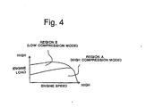
- the engine is provided with a high compression ratio mode to set the compression ratio of the engine to be high in an operation region on the relatively low load side and a low compression ratio mode to set the compression ratio of the engine to be low in an operation region on the relatively high load side.
- Either one of the compression ratio modes is selected according to the operating condition of the engine. For instance, when the engine load is sufficiently high (depending on the rotation speed), the invention contemplates operating the engine at a lower compression ratio. The result is that heat efficiency is improved in the low-load side operation region by increasing the compression ratio of the engine. Alternatively, the occurrence of engine knocking is effectively suppressed in the high-load side operation region by lowering the compression ratio of the engine.
- Fig. 4 is exemplary. It will be evident to those of ordinary skill in the art that the thresholds at which an engine should switch to or from a low compression mode (that suppresses knocking) to a high compression mode (that improves heat efficiency at low loads) are dependent upon many factors, including the geometry of the engine, and will be different for each engine configuration and different for the goals of the engine design (e.g. depending on a balance of desired performance, efficiency, emissions, knock reduction and/or other goals). Accordingly, appropriate data for generating a map such as Fig. 4 can be determined empirically or by modeling, but the generation of a map such as Fig. 4 for a particular engine configuration is a task that can be carried out by the exercise of ordinary skill.
- the invention does not depend upon any particular factors considered by a designer in selecting the location of the line separating Mode A from Mode B. Nonetheless, according to the invention, the "switching" thresholds (e.g., the line separating Mode A from Mode B) are selected to result in suppression of knocking in the low compression mode and improved heat efficiency for low loads at the high compression mode.
- the "switching" thresholds e.g., the line separating Mode A from Mode B
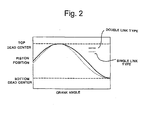
- Fig. 2 shows the piston motion state of an engine having a double-link type piston crank mechanism in comparison with the piston motion state of an engine having a single-link type piston crank mechanism.
- the height from the crankshaft to the top surface of the piston is the same in both engines.
- the slope of the lines in Fig. 2 represents velocity and the gradient of the slope of the lines in Fig. 2 represents acceleration.
- the action of the double-link type piston crank mechanism reduces the maximum acceleration of the piston in the region of top dead centre, and thus reduces the amount of displacement of the piston in the region of the top dead centre. Consequently, the piston can approach top dead centre relatively early, and can stay longer in the vicinity the top dead centre than is possible in a single-link type piston crank mechanism.
- the double-link type piston crank mechanism can make a high-temperature and high-pressure state in the vicinity of the top dead centre persist for a relatively longer time so that combustion stability, particularly in the low-load side operation region, can be improved.
- Fig. 3 is a flowchart illustrating the contents of a compression ratio mode switching control and a combustion mode switch control according to the invention.
- the flowchart is repeatedly executed by the Engine Control Unit ("ECU") 21 at predetermined time intervals, for example every 10 milliseconds.
- predetermined time interval does not preclude a time interval that varies in a predetermined manner.
- the engine speed and the engine load are detected based on the signals from the crank angle sensor 31 (one type of engine speed sensor) and the acceleration pedal depression sensor 33 (one type of engine load sensor).
- the engine load is detected from the depression amount of the acceleration pedal in this embodiment, the engine load may be detected from the amount of fuel injection, the target torque of the engine, or the like.
- engine speed can be detected in other fashions other than based on the crank angle sensor.
- step S2 by referring to a compression ratio mode map such as that shown in Fig. 4, it is determined whether the operating condition of the engine, meaning a combination of the engine speed and the engine load, is in region "A" or region "B". Those operating conditions in region “A” are set on the low-load side of the entire operation region, and those operating conditions in region “B” are set on the higher-load side to the region "A”. The flow of control then proceeds to step S3 or step S4 according to the region where the operating condition lies.
- the boundary between "A” and “B” may be empirically acquired.
- the data defining the boundary are stored in ROM (Read Only Memory) in the ECU 21.
- the boundary is a set of operating conditions where engine knocking can be barely restrained at the high compression ratio when the combustion mode is appropriately selected.
- the operation region to be able to suppress the knocking is set to the region "A".
- region "A” of Fig. 4 includes the set of combinations of engine load and engine speed (operating conditions) that restrain knocking during high compression ratio operation.
- the border between “A” and “ B” is set to continue to restrain knocking while the engine is switched to low compression ratio operation.
- Region “B” includes the set of operating conditions that restrain knocking during low compression mode operation.
- step S3 a target compression ratio of the engine is set to a predetermined high compression ratio, and the actuator 20 is controlled in such a way as to achieve the set target compression ratio (i.e. setting a higher top dead centre height). If the operating condition lies in the region "B”, flow proceeds to step S4 instead of step S3. At step S4, a target compression ratio of the engine is set to a predetermined low compression ratio that is lower than the compression ratio set at step S3, and the actuator 20 is controlled in such a way as to achieve the set target compression ratio (i.e. setting a lower top dead centre height).
- an actual compression ratio in the next cycle is predicted. Prediction is employed to compensate for the time lag associated for the actuator 20 to operate to move the piston into the necessary position. In other words, even when the target compression ratio is set and the control of the actuator 20 is initiated at step S3 or S4, there is a certain time lag for the actual compression ratio to reach the target compression ratio. This time lag is substantial because of the relatively slow response speed of the actuator 20 compared to, for example, the faster response speed of changing the fuel injection amount, changing the fuel injection timing or changing the ignition timing.
- the prediction is based on the response speed of the actuator 20.
- the actual compression ratio is predicted by performing a delay process which correlates the response characteristic of the actuator 20, the current compression ratio (i.e., the actual compression ratio predicted in the previous cycle), and the target compression ratio set at step S3 or S4.
- the invention does not depend upon the particular prediction, and the appropriate time lag and appropriate prediction is readily determined for a particular engine configuration; for example by modeling, or empirically, by measuring the compression ratio in a test engine as the actuator is controlled.
- step S6 referring to a combustion mode map such as the one depicted in Fig. 5, it is determined whether the operating condition of the engine (again, a combination of engine load and engine speed) lies in a particular combustion mode region.
- Fig. 5 is again, merely exemplary.
- the data of the boundaries which form the combustion mode map are stored in ROM.
- step S6 referring to a combustion mode map such as the one shown in Fig. 5, it is determined whether the operating condition of the engine lies in a region "X" which is set when the engine operates at a low speed and under a low load, a region “Y” which is set when the engine operates at a higher speed and under a higher load than region "X", or a region “Z” which is set when the engine operates at a yet higher speed and under a yet higher load than region "Y”.
- the flow then proceeds to one of steps S7, S8 and S9 according to the operating condition.
- step S7 the combustion mode of the engine is set to the stratified lean combustion mode, and the fuel injection timing and the ignition timing are calculated based on the operating condition by referring to predetermined maps prepared beforehand for the stratified lean combustion mode.
- the fuel injection timing map and the ignition timing map are stored in ROM and are acquired by experiment in consideration of the compression ratio of the engine being changed according to the map shown in Fig. 4. Such experiments would be different for each engine configuration, but are generally routine and generally require only ordinary skill.
- the region "X" is wholly contained within the region "A", although the invention does not require such.
- the tables are set (acquired by experiment) such that the fuel injection timing and the ignition timing are suitable for executing stratified lean combustion at the high compression ratio of region "A" (according to well understood principles of advancing or retarding injection and/or ignition, e.g. to achieve efficient combustion).
- step S8 the combustion mode of the engine is set to the homogeneous lean combustion mode, and the fuel injection timing and the ignition timing are calculated based on the operating condition by referring to predetermined maps prepared beforehand for the homogeneous lean combustion mode.
- the combustion mode region "Y" overlaps both the compression mode region "A” and the compression mode region "B", although the invention does not require such.
- the individual maps for fuel injection timing and ignition timing are set (acquired by experiment) in such a way that the timing of each is suitable for executing homogeneous lean combustion at a high compression ratio for combinations of engine speed and engine load where the combustion mode region "Y" and the compression mode region "A" overlap each other.
- the maps are set such that the fuel injection timing and the ignition timing are suitable for executing homogeneous lean combustion at a low compression ratio for combinations of engine speed and engine load where the combustion mode region "Y" and the compression mode region “B” overlap each other.
- such settings or experiments would result in different predetermined maps for each engine configuration, but generally require only ordinary skill.
- the amount of fuel injected is also predetermined, and the amount for one mode need not be the same as any other mode.
- step S9 the combustion mode of the engine is set to the homogeneous stoichiometric combustion mode, and the fuel injection timing and the ignition timing are set referring to predetermined maps prepared beforehand for the homogeneous stoichiometric combustion mode.
- the individual maps are, as described above with respect to the homogenous lean combustion mode, set by routine experiment in consideration of the compression ratio of the engine being changed according to the map shown in Fig. 4. For example, in this particular embodiment, it is necessary to take into account that the combustion mode region "Z" overlaps both the compression mode region "A" and the compression mode region "B", although the invention does not require such.
- step S10 the actual compression ratio was predicted based on the response characteristics of the actuator 20, the "current" compression ratio, and the target compression ratio.
- step S10 the fuel injection timing and the ignition timing (set at step S7, S8 or S9) are corrected based on the difference between the "current" compression ratio and the target compression ratio. The correction is performed considering that the fuel injection timing and the ignition timing set in step S7, S8 or S9 took values based on the assumption that the actual compression ratio had already become the target compression ratio.
- the actual compression ratio changes with a delay with respect to the target compression ratio, due to the operation delay or response delay of the actuator 20.
- the invention does not depend upon the particular correction applied, and the appropriate correction to fuel injection timing and/or ignition timing is readily determined for a particular engine configuration, for example, by modeling, or empirically by measuring desired combustion characteristics such as emissions or crankshaft power in a test engine as the actuator 20 is controlled.
- the compression ratio mode and the combustion mode of the engine are switched from one to the other according to the operating condition of the engine (combination of engine load and engine speed).
- the engine is provided with a double-link type piston crank mechanism 30, as seen in Fig. 1, so constructed as to provide piston motion wherein the acceleration of the piston in the vicinity of top dead centre is lower than the acceleration of the piston in the vicinity of bottom dead centre.
- An operating condition of the engine is determined (step S2, preferably directly or indirectly measured, but possibly predicted, modeled, or inferred), and the engine is operated at an air-fuel ratio leaner than a stoichiometric air-fuel ratio (lean combustion) when it is determined that the operating condition of the engine lies in a predetermined partial load region (step S7 or S8), thus making it possible to enhance the heat efficiency and improve the fuel consumption, compared with earlier technology which performs exhaust gas recirculation in a partial load region.
- a "partial load region” is a set of combinations of engine speed and engine load ("region") in which the engine load is not at a maximum (“partial load”).
- An "operating region” can include one or more partial load regions.
- the action of the double-link type piston crank mechanism 30 causes the piston 3 to stay longer in the vicinity of the top dead centre, so that a high-temperature and high-pressure field can be produced and maintained in the combustion chamber 4, and termination of flame propagation caused by the downward movement of the piston 3 can be suppressed. Accordingly, combustion stability can be maintained even when lean combustion is carried out in a relatively wide operation region.
- the thresholds at which an engine should switch to or from a stratified lean combustion mode that enhances heat efficiency with the very best fuel consumption
- homogenous lean combustion mode that enhances heat efficiency with improved fuel consumption
- stoichiometric combustion mode that is used at times when a lean mixture is disadvantageous, such as during the very highest power and speed demands
- appropriate data for generating a map can be determined empirically or modeled, but the generation of a map such as Fig.
- the "switching" thresholds are selected to result in i) enhanced heat efficiency and the lowest fuel consumption in the stratified lean combustion mode, ii) in enhanced heat efficiency and improved fuel consumption in the homogenous lean combustion mode, and ii) in the very highest power generation in the stoichiometric combustion mode.
- stratified combustion or homogeneous combustion can be set as the lean combustion system, and may be switched according to the operating condition of the engine in such a way that stratified combustion is done in an operation region in the partial load region which is set to a relatively low-load side and a lower-speed side (i.e., the region "X" in Fig. 5), and homogeneous combustion is done in an operation region in the partial load region which is set to a higher load side and a higher speed side than the region "X" (i.e., the region Y in Fig. 5).
- step S9 When the operating condition of the engine lies in an operating region which is set outside a predetermined partial load region (i.e., the region "Z" in Fig. 5, which is outside the lean combustion regions "X" and “Y"), the combustion system of the engine is switched to the homogeneous stoichiometric combustion (step S9) to be able to carry out high-power operation.
- the coupled position of the double-link type piston crank mechanism 30 and the engine body i.e. the position of the eccentric portion 17
- the actuator 20 i.e. the compression ratio change mechanism
- the top dead centre of the piston 3 is lowered to reduce the compression ratio of the engine (step S4), making it possible to effectively suppress knocking.
- an engine control system such as that depicted in Fig. 1 includes a double-link piston and cylinder system 30 arranged to eccentrically move a piston 3 within a cylinder such that piston acceleration is slowed at a top dead centre position.
- the top dead centre position is adjustable via the actuator 20.
- An engine load sensor 33 measures engine load
- an engine speed sensor 31 measures engine speed
- a fuel injection system (including valve 11) causes an injection of fuel of a variable amount into the cylinder
- an ignition system including plug 12 causes an ignition of fuel in the cylinder.
- An engine control unit (including ECU 21 and associated control lines) is connected to each of the engine load sensor 33, the engine speed sensor 31, fuel injection system (including valve 11), and the ignition system (including plug 12).
- the engine control unit circuit selects a combustion mode from combustion modes including two lean combustion modes and a stoichiometric combustion mode.
- the engine control unit is capable of adjusting the top dead centre position of the double-link piston and cylinder system, the variable amount of fuel, timing of the injection of fuel, or timing of the ignition system according to the selection of the combustion mode.
- the engine control unit selects one of the two lean combustion modes or the stoichiometric combustion mode depending upon a combination of engine load measured by the engine load sensor and engine speed measured by the engine speed sensor.
- the lean combustion mode selected by the engine control unit circuit may be selected from one of a stratified lean combustion mode or a homogenous lean combustion mode.
- stratified lean combustion mode the top dead centre position of the double-link piston and cylinder system, the variable amount of fuel, and the timing of the fuel injection are adjusted to create a stratified lean combustion region in the cylinder in which different air-fuel ratios occur at the top of the cylinder.
- the aformentioned variables are again adjusted to create a homogenous lean combustion region with the same air-fuel ratio in substantially all of the top of the cylinder.
- the operating region where lean combustion becomes possible becomes wider so that even when lean combustion is executed, the amount of nitrogen oxide which is produced during combustion can be suppressed to a sufficiently low level, and using a highly ignitable fuel can further widen the operation region where lean combustion is possible.
- a cylinder means one or more cylinders;
- a double-link piston crank mechanism means one or more of these, and so on, as appropriate, and unless otherwise specified.
- Determining includes measuring, modeling, predicting, or other means of substantially accurately obtaining a desired value.
Landscapes
- Engineering & Computer Science (AREA)
- Chemical & Material Sciences (AREA)
- Combustion & Propulsion (AREA)
- Mechanical Engineering (AREA)
- General Engineering & Computer Science (AREA)
- Theoretical Computer Science (AREA)
- Signal Processing (AREA)
- Electrical Control Of Air Or Fuel Supplied To Internal-Combustion Engine (AREA)
- Output Control And Ontrol Of Special Type Engine (AREA)
- Combustion Methods Of Internal-Combustion Engines (AREA)
- Control Of Vehicle Engines Or Engines For Specific Uses (AREA)
- Combined Controls Of Internal Combustion Engines (AREA)
Abstract
Description
Claims (21)
- An engine comprising:a piston (3) which is slidably received within an associated cylinder and a crankshaft (15) connected to the piston (3) for reciprocably moving the piston (3) with respect to the cylinder;a multi-link piston crank mechanism (30) connected to the crankshaft (15) for controlling movement of the piston (3) such that an acceleration of the piston (3) at top dead centre is less than an acceleration of the piston (3) at bottom dead centre;determining means to determine an operating condition of the engine; andcombustion mode control means to control a combustion mode of the engine to operate at an air-fuel ratio leaner than a stoichiometric air-fuel ratio when the determining means determines that the operating condition of the engine resides in a predetermined first operating region.
- The engine according to claim 1, wherein the combustion mode control means controls the engine such that a homogeneous air-fuel mixture is formed and combusted in the cylinder when the combustion mode control means controls the engine to operate at the air-fuel ratio leaner than the stoichiometric air-fuel ratio.
- The engine according to claim 1, wherein the combustion mode control means controls the engine such that a stratified air-fuel mixture with different air-fuel ratios in different strata is formed and combusted in the cylinder when the combustion mode control means controls the engine to operate at the air-fuel ratio leaner than the stoichiometric air-fuel ratio.
- The engine according to claim 1, wherein the combustion mode control means controls the engine to operate at the stoichiometric air-fuel ratio when the determining means determines that the operating condition of the engine is not in the predetermined first operating region.
- The engine according to any of claims 1 to 4 including compression ratio change means (20) associated with the multi-link piston crank mechanism (30) for adjusting a top dead centre position of the piston (3) in order to change the compression ratio of the engine, wherein when the determining means determines that the operating condition of the engine is in a second predetermined operating region, the compression ratio change means raises the top dead centre of the piston (3) to increase the compression ratio of the engine.
- The engine according to claim 5, wherein the compression ratio change means (20) lowers the top dead centre position of the piston (3) to decrease the compression ratio of the engine when the determining means determines that the operating condition of the engine is in the remaining partial load region in which an engine load is higher than in the predetermined partial load region.
- The engine according to claim 5, wherein the multi-link piston crank mechanism (30) controls the piston (3) such that an acceleration of the piston (3) at top dead centre is lowered when the compression ratio change means (20) raises the top dead centre position of the piston (3).
- The engine according to any of claims 1 to 7, wherein the operating condition is determined according to a combination of engine load and engine speed.
- An engine control system for use in the engine according to any of claims 1 to 8, the engine control system including an engine control unit (21) providing the combustion mode control means.
- A method of controlling an engine comprising:eccentrically moving a piston (3) within a cylinder such that an acceleration of the piston (3) at a top dead centre position is less than an acceleration of the piston (3) at a bottom dead centre position;calculating an operating condition of the engine;determining if the calculated operating condition of the engine resides within one or more predetermined operating regions; andoperating the engine at an air-fuel ratio leaner than a stoichiometric air-fuel ratio when the calculated operating condition of the engine is in a predetermined first operating region.
- The method according to claim 10, further comprising, when operating the engine at the air-fuel ratio leaner than the stoichiometric air-fuel ratio,
forming a homogeneous air-fuel mixture within the cylinder and combusting the homogeneous air-fuel mixture in the cylinder. - The method according to claim 10, further comprising, when operating the engine at the air-fuel ratio leaner than the stoichiometric air-fuel ratio,
forming a stratified air-fuel mixture in the cylinder having different air-fuel ratios in different strata, and combusting the stratified air-fuel mixture in the cylinder. - The method according to any of claims 10 to 12, further comprising:adjusting the top dead centre position of the piston (3) to increase a compression ratio of the engine when the operating condition of the engine is in a predetermined second operating region, andadjusting the top dead centre position of the piston (3) to decrease a compression ratio of the engine when the operating condition of the engine is not in the predetermined second operating region.
- The method according to any of claims 10 to 13, further comprising determining the operating condition according to a combination of engine load and engine speed.
- An engine comprising:wherein the engine control unit (21) is arranged to select a combustion mode from a plurality of combustion modes including a lean combustion mode and a stoichiometric combustion mode and wherein, according to the selection of a combustion mode, the engine control unit (21) is capable of adjusting the top dead centre position of the multi-link piston and cylinder system (30), the variable amount of fuel, the timing of the injection of fuel, and the timing of the ignition system (12).a multi-link piston and cylinder system (30) arranged to eccentrically move a piston (3) within a cylinder such that piston acceleration is slowed at a top dead centre position, said top dead centre position being adjustable;engine load sensing means (33);engine speed sensing means (31);a fuel injection system (11) for injecting a variable amount of fuel into the cylinder;an ignition system (12) that causes an ignition of fuel in the cylinder;an engine control unit (21) connected to the engine load sensing means (33), the engine speed sensing means (31), the fuel injection system (11), and the ignition system (12);
- The engine according to claim 15, wherein the engine control unit (21) selects the lean combustion mode or the stoichiometric combustion mode depending upon a combination of engine load measured by the engine load sensing means (33) and engine speed measured by the engine speed sensing means (31).
- The engine according to claim 15 or claim 16, wherein the lean combustion mode selected by said engine control unit (21) is selected from one of:a stratified lean combustion mode, in which at least the top dead centre position of the multi-link piston and cylinder system (30), the variable amount of fuel, and timing of the injection of fuel are adjusted to create a stratified lean combustion region in the cylinder in which different air-fuel ratios occur in different parts of a top of the cylinder, anda homogenous lean combustion mode, in which at least the top dead centre position of the multi-link piston and cylinder system (30), the variable amount of fuel, and timing of the injection of fuel are adjusted to create a homogenous lean combustion region in the cylinder in which the same air-fuel ratio occurs in substantially all of the top of the cylinder.
- The engine according to any of claims 15 to 17, wherein the top dead centre position of the piston (3) is adjustable between a high compression mode top dead centre position and a low compression mode top dead centre position.
- The engine according to claim 18, wherein the engine control unit (21) adjusts the top dead centre position of the piston (3) to the high compression mode top dead centre position when selecting the stratified lean combustion mode.
- The engine according to claim 18, wherein when the engine control unit (21) selects the homogenous lean combustion mode or the stoichiometric combustion mode, the engine control unit (21) adjusts the top dead centre position of the piston (3) to the low compression mode top dead centre position or the high compression mode top dead centre position depending upon a combination of engine load measured by the engine load sensing means (33) and engine speed measured by the engine speed sensing means (31).
- An engine control system for use in the engine according to any of claims 15 to 20, the engine control system including the engine control unit (21) for selecting the combustion mode.
Applications Claiming Priority (2)
| Application Number | Priority Date | Filing Date | Title |
|---|---|---|---|
| JP2004166775A JP4403885B2 (en) | 2004-06-04 | 2004-06-04 | Engine with multi-link piston crank mechanism |
| JP2004166775 | 2004-06-04 |
Publications (3)
| Publication Number | Publication Date |
|---|---|
| EP1602812A2 true EP1602812A2 (en) | 2005-12-07 |
| EP1602812A3 EP1602812A3 (en) | 2009-02-04 |
| EP1602812B1 EP1602812B1 (en) | 2011-08-10 |
Family
ID=34941580
Family Applications (1)
| Application Number | Title | Priority Date | Filing Date |
|---|---|---|---|
| EP05253457A Expired - Lifetime EP1602812B1 (en) | 2004-06-04 | 2005-06-04 | Controlling an engine with a multi-link type piston crank mechanism |
Country Status (4)
| Country | Link |
|---|---|
| US (1) | US7159543B2 (en) |
| EP (1) | EP1602812B1 (en) |
| JP (1) | JP4403885B2 (en) |
| AT (1) | ATE519934T1 (en) |
Cited By (1)
| Publication number | Priority date | Publication date | Assignee | Title |
|---|---|---|---|---|
| WO2012139609A1 (en) * | 2011-04-15 | 2012-10-18 | Daimler Ag | Method for operating an adjustment device for variably adjusting a compression ration of an internal combustion engine |
Families Citing this family (18)
| Publication number | Priority date | Publication date | Assignee | Title |
|---|---|---|---|---|
| US7228824B2 (en) * | 2005-11-03 | 2007-06-12 | Ford Global Technologies, Llc | Internal combustion engine having variable compression ratio selection as a function of projected engine speed |
| DE102006003737B3 (en) * | 2006-01-24 | 2007-06-06 | Iav Gmbh Ingenieurgesellschaft Auto Und Verkehr | Reciprocating-piston combustion engine, has piston connected to pulling and pressing rod guided parallel to cylinder axis and pulling and pressing rod interacts with transmission lever along extended channel |
| JP4821373B2 (en) * | 2006-03-06 | 2011-11-24 | 日産自動車株式会社 | Variable compression ratio engine |
| FR2914950B1 (en) * | 2007-04-16 | 2012-06-15 | Vianney Rabhi | DEVICE FOR MEASURING DIRECTLY ON THE PISTON THE EFFECTIVE VOLUMETRIC RATIO OF A VARIABLE COMPRESSION RATE MOTOR. |
| JP4450025B2 (en) * | 2007-07-12 | 2010-04-14 | トヨタ自動車株式会社 | Spark ignition internal combustion engine |
| JP4882912B2 (en) * | 2007-08-10 | 2012-02-22 | 日産自動車株式会社 | Variable compression ratio internal combustion engine |
| JP4941168B2 (en) * | 2007-08-14 | 2012-05-30 | 日産自動車株式会社 | Supercharged engine and supercharger input torque control device for supercharged engine |
| US8100097B2 (en) * | 2007-10-26 | 2012-01-24 | Nissan Motor Co., Ltd. | Multi-link engine |
| JP5029290B2 (en) * | 2007-10-29 | 2012-09-19 | 日産自動車株式会社 | Variable compression ratio engine |
| WO2013141089A1 (en) * | 2012-03-23 | 2013-09-26 | 日産自動車株式会社 | Control method and control device of internal combustion engine |
| JP2014034927A (en) * | 2012-08-09 | 2014-02-24 | Honda Motor Co Ltd | Multiple link-type internal combustion engine |
| JP5971396B2 (en) * | 2013-02-22 | 2016-08-17 | 日産自動車株式会社 | Control device and control method for internal combustion engine |
| CN105121816B (en) * | 2013-04-23 | 2017-06-30 | 日产自动车株式会社 | The control device and control method of internal combustion engine |
| US10125679B2 (en) * | 2016-03-29 | 2018-11-13 | GM Global Technology Operations LLC | Independent compression and expansion ratio engine with variable compression ratio |
| EP3640462B1 (en) * | 2017-06-15 | 2021-01-27 | Nissan Motor Co., Ltd. | Control device and control method for direct-injection engine |
| EP3640463B8 (en) * | 2017-06-15 | 2021-06-23 | Nissan Motor Co., Ltd. | Control device and control method for direct-injection engine |
| US10428863B2 (en) * | 2017-06-21 | 2019-10-01 | GM Global Technology Operations LLC | Variable compression ratio engine |
| CN118188155A (en) * | 2024-03-12 | 2024-06-14 | 李斯特技术中心(天津)有限公司 | A high expansion ratio multi-link mechanism for an engine |
Family Cites Families (4)
| Publication number | Priority date | Publication date | Assignee | Title |
|---|---|---|---|---|
| JP3968957B2 (en) * | 2000-06-02 | 2007-08-29 | 日産自動車株式会社 | Internal combustion engine |
| US6564769B2 (en) * | 2001-09-04 | 2003-05-20 | Ford Global Technologies, Llc | Method and system for operating a direct injection spark internal combustion engine having variable compression ratio modes |
| JP2003232233A (en) | 2001-12-06 | 2003-08-22 | Nissan Motor Co Ltd | Control device for internal combustion engine |
| JP3885740B2 (en) * | 2003-02-06 | 2007-02-28 | トヨタ自動車株式会社 | Control of internal combustion engine when changing two operation modes with different compression ratio and air-fuel ratio |
-
2004
- 2004-06-04 JP JP2004166775A patent/JP4403885B2/en not_active Expired - Fee Related
-
2005
- 2005-06-02 US US11/142,892 patent/US7159543B2/en not_active Expired - Lifetime
- 2005-06-04 EP EP05253457A patent/EP1602812B1/en not_active Expired - Lifetime
- 2005-06-04 AT AT05253457T patent/ATE519934T1/en not_active IP Right Cessation
Cited By (1)
| Publication number | Priority date | Publication date | Assignee | Title |
|---|---|---|---|---|
| WO2012139609A1 (en) * | 2011-04-15 | 2012-10-18 | Daimler Ag | Method for operating an adjustment device for variably adjusting a compression ration of an internal combustion engine |
Also Published As
| Publication number | Publication date |
|---|---|
| JP2005344644A (en) | 2005-12-15 |
| US20050268870A1 (en) | 2005-12-08 |
| JP4403885B2 (en) | 2010-01-27 |
| EP1602812A3 (en) | 2009-02-04 |
| EP1602812B1 (en) | 2011-08-10 |
| US7159543B2 (en) | 2007-01-09 |
| ATE519934T1 (en) | 2011-08-15 |
Similar Documents
| Publication | Publication Date | Title |
|---|---|---|
| EP1602812B1 (en) | Controlling an engine with a multi-link type piston crank mechanism | |
| EP2263000B1 (en) | Control apparatus for a cylinder direct-injection internal combustion engine | |
| JP3500951B2 (en) | Non-throttle compression-ignition internal combustion engine and control method thereof | |
| KR100284523B1 (en) | Control device of internal injection type spark ignition internal combustion engine | |
| EP1515031B1 (en) | System and method for controlling spark-ignition internal combustion engine | |
| JP4946173B2 (en) | Internal combustion engine | |
| EP1083324A2 (en) | Control system for self-ignition type gasoline engine | |
| KR101016924B1 (en) | Fuel injection control device and fuel injection method of internal combustion engine | |
| JP2003003873A (en) | Compression self-ignition internal combustion engine | |
| JP2001207889A (en) | Combustion control device for internal combustion engine | |
| JP2002276404A (en) | Compression ignition type internal combustion engine | |
| JP4311604B2 (en) | Control device for self-ignition engine | |
| JP4032650B2 (en) | Combustion control device for internal combustion engine | |
| JP5359590B2 (en) | Variable compression ratio internal combustion engine | |
| EP3640462A1 (en) | Control device and control method for direct-injection engine | |
| US7104249B2 (en) | Direct fuel injection/spark ignition engine control device | |
| JP4186782B2 (en) | Internal combustion engine | |
| JP2000192846A (en) | Combustion control device for internal combustion engine | |
| JP2004204745A (en) | Engine control apparatus and method | |
| JP2007239550A (en) | Variable compression ratio engine | |
| JP4425839B2 (en) | Control device for internal combustion engine | |
| JP2008002328A (en) | Multi-fuel internal combustion engine | |
| JP2018096311A (en) | Control device of internal combustion engine | |
| JP2010159683A (en) | Internal combustion engine | |
| JP2006144629A (en) | Control device for internal combustion engine |
Legal Events
| Date | Code | Title | Description |
|---|---|---|---|
| PUAI | Public reference made under article 153(3) epc to a published international application that has entered the european phase |
Free format text: ORIGINAL CODE: 0009012 |
|
| AK | Designated contracting states |
Kind code of ref document: A2 Designated state(s): AT BE BG CH CY CZ DE DK EE ES FI FR GB GR HU IE IS IT LI LT LU MC NL PL PT RO SE SI SK TR |
|
| AX | Request for extension of the european patent |
Extension state: AL BA HR LV MK YU |
|
| RIN1 | Information on inventor provided before grant (corrected) |
Inventor name: KUBO, MASAAKI Inventor name: HOTTA, ISAMU Inventor name: NODA, TORU Inventor name: MOTEKI, KATSUYA |
|
| PUAL | Search report despatched |
Free format text: ORIGINAL CODE: 0009013 |
|
| AK | Designated contracting states |
Kind code of ref document: A3 Designated state(s): AT BE BG CH CY CZ DE DK EE ES FI FR GB GR HU IE IS IT LI LT LU MC NL PL PT RO SE SI SK TR |
|
| AX | Request for extension of the european patent |
Extension state: AL BA HR LV MK YU |
|
| RIC1 | Information provided on ipc code assigned before grant |
Ipc: F02D 15/02 20060101AFI20050824BHEP Ipc: F02B 67/00 20060101ALI20081230BHEP |
|
| 17P | Request for examination filed |
Effective date: 20090804 |
|
| 17Q | First examination report despatched |
Effective date: 20090904 |
|
| AKX | Designation fees paid |
Designated state(s): AT BE BG CH CY CZ DE DK EE ES FI FR GB GR HU IE IS IT LI LT LU MC NL PL PT RO SE SI SK TR |
|
| GRAP | Despatch of communication of intention to grant a patent |
Free format text: ORIGINAL CODE: EPIDOSNIGR1 |
|
| GRAS | Grant fee paid |
Free format text: ORIGINAL CODE: EPIDOSNIGR3 |
|
| GRAA | (expected) grant |
Free format text: ORIGINAL CODE: 0009210 |
|
| AK | Designated contracting states |
Kind code of ref document: B1 Designated state(s): AT BE BG CH CY CZ DE DK EE ES FI FR GB GR HU IE IS IT LI LT LU MC NL PL PT RO SE SI SK TR |
|
| REG | Reference to a national code |
Ref country code: GB Ref legal event code: FG4D |
|
| REG | Reference to a national code |
Ref country code: CH Ref legal event code: EP |
|
| REG | Reference to a national code |
Ref country code: IE Ref legal event code: FG4D |
|
| REG | Reference to a national code |
Ref country code: DE Ref legal event code: R096 Ref document number: 602005029398 Country of ref document: DE Effective date: 20111006 |
|
| REG | Reference to a national code |
Ref country code: NL Ref legal event code: VDEP Effective date: 20110810 |
|
| LTIE | Lt: invalidation of european patent or patent extension |
Effective date: 20110810 |
|
| PG25 | Lapsed in a contracting state [announced via postgrant information from national office to epo] |
Ref country code: FI Free format text: LAPSE BECAUSE OF FAILURE TO SUBMIT A TRANSLATION OF THE DESCRIPTION OR TO PAY THE FEE WITHIN THE PRESCRIBED TIME-LIMIT Effective date: 20110810 Ref country code: NL Free format text: LAPSE BECAUSE OF FAILURE TO SUBMIT A TRANSLATION OF THE DESCRIPTION OR TO PAY THE FEE WITHIN THE PRESCRIBED TIME-LIMIT Effective date: 20110810 Ref country code: PT Free format text: LAPSE BECAUSE OF FAILURE TO SUBMIT A TRANSLATION OF THE DESCRIPTION OR TO PAY THE FEE WITHIN THE PRESCRIBED TIME-LIMIT Effective date: 20111212 Ref country code: LT Free format text: LAPSE BECAUSE OF FAILURE TO SUBMIT A TRANSLATION OF THE DESCRIPTION OR TO PAY THE FEE WITHIN THE PRESCRIBED TIME-LIMIT Effective date: 20110810 Ref country code: SE Free format text: LAPSE BECAUSE OF FAILURE TO SUBMIT A TRANSLATION OF THE DESCRIPTION OR TO PAY THE FEE WITHIN THE PRESCRIBED TIME-LIMIT Effective date: 20110810 Ref country code: IS Free format text: LAPSE BECAUSE OF FAILURE TO SUBMIT A TRANSLATION OF THE DESCRIPTION OR TO PAY THE FEE WITHIN THE PRESCRIBED TIME-LIMIT Effective date: 20111210 |
|
| REG | Reference to a national code |
Ref country code: AT Ref legal event code: MK05 Ref document number: 519934 Country of ref document: AT Kind code of ref document: T Effective date: 20110810 |
|
| PG25 | Lapsed in a contracting state [announced via postgrant information from national office to epo] |
Ref country code: PL Free format text: LAPSE BECAUSE OF FAILURE TO SUBMIT A TRANSLATION OF THE DESCRIPTION OR TO PAY THE FEE WITHIN THE PRESCRIBED TIME-LIMIT Effective date: 20110810 Ref country code: AT Free format text: LAPSE BECAUSE OF FAILURE TO SUBMIT A TRANSLATION OF THE DESCRIPTION OR TO PAY THE FEE WITHIN THE PRESCRIBED TIME-LIMIT Effective date: 20110810 Ref country code: CY Free format text: LAPSE BECAUSE OF FAILURE TO SUBMIT A TRANSLATION OF THE DESCRIPTION OR TO PAY THE FEE WITHIN THE PRESCRIBED TIME-LIMIT Effective date: 20110810 Ref country code: SI Free format text: LAPSE BECAUSE OF FAILURE TO SUBMIT A TRANSLATION OF THE DESCRIPTION OR TO PAY THE FEE WITHIN THE PRESCRIBED TIME-LIMIT Effective date: 20110810 |
|
| PG25 | Lapsed in a contracting state [announced via postgrant information from national office to epo] |
Ref country code: BE Free format text: LAPSE BECAUSE OF FAILURE TO SUBMIT A TRANSLATION OF THE DESCRIPTION OR TO PAY THE FEE WITHIN THE PRESCRIBED TIME-LIMIT Effective date: 20110810 |
|
| PG25 | Lapsed in a contracting state [announced via postgrant information from national office to epo] |
Ref country code: CZ Free format text: LAPSE BECAUSE OF FAILURE TO SUBMIT A TRANSLATION OF THE DESCRIPTION OR TO PAY THE FEE WITHIN THE PRESCRIBED TIME-LIMIT Effective date: 20110810 Ref country code: SK Free format text: LAPSE BECAUSE OF FAILURE TO SUBMIT A TRANSLATION OF THE DESCRIPTION OR TO PAY THE FEE WITHIN THE PRESCRIBED TIME-LIMIT Effective date: 20110810 |
|
| PG25 | Lapsed in a contracting state [announced via postgrant information from national office to epo] |
Ref country code: EE Free format text: LAPSE BECAUSE OF FAILURE TO SUBMIT A TRANSLATION OF THE DESCRIPTION OR TO PAY THE FEE WITHIN THE PRESCRIBED TIME-LIMIT Effective date: 20110810 Ref country code: RO Free format text: LAPSE BECAUSE OF FAILURE TO SUBMIT A TRANSLATION OF THE DESCRIPTION OR TO PAY THE FEE WITHIN THE PRESCRIBED TIME-LIMIT Effective date: 20110810 Ref country code: IT Free format text: LAPSE BECAUSE OF FAILURE TO SUBMIT A TRANSLATION OF THE DESCRIPTION OR TO PAY THE FEE WITHIN THE PRESCRIBED TIME-LIMIT Effective date: 20110810 |
|
| PLBE | No opposition filed within time limit |
Free format text: ORIGINAL CODE: 0009261 |
|
| STAA | Information on the status of an ep patent application or granted ep patent |
Free format text: STATUS: NO OPPOSITION FILED WITHIN TIME LIMIT |
|
| PG25 | Lapsed in a contracting state [announced via postgrant information from national office to epo] |
Ref country code: DK Free format text: LAPSE BECAUSE OF FAILURE TO SUBMIT A TRANSLATION OF THE DESCRIPTION OR TO PAY THE FEE WITHIN THE PRESCRIBED TIME-LIMIT Effective date: 20110810 |
|
| 26N | No opposition filed |
Effective date: 20120511 |
|
| REG | Reference to a national code |
Ref country code: DE Ref legal event code: R097 Ref document number: 602005029398 Country of ref document: DE Effective date: 20120511 |
|
| PG25 | Lapsed in a contracting state [announced via postgrant information from national office to epo] |
Ref country code: MC Free format text: LAPSE BECAUSE OF NON-PAYMENT OF DUE FEES Effective date: 20120630 |
|
| REG | Reference to a national code |
Ref country code: CH Ref legal event code: PL |
|
| REG | Reference to a national code |
Ref country code: CH Ref legal event code: PL |
|
| REG | Reference to a national code |
Ref country code: IE Ref legal event code: MM4A |
|
| PG25 | Lapsed in a contracting state [announced via postgrant information from national office to epo] |
Ref country code: CH Free format text: LAPSE BECAUSE OF NON-PAYMENT OF DUE FEES Effective date: 20120630 Ref country code: IE Free format text: LAPSE BECAUSE OF NON-PAYMENT OF DUE FEES Effective date: 20120604 Ref country code: LI Free format text: LAPSE BECAUSE OF NON-PAYMENT OF DUE FEES Effective date: 20120630 Ref country code: ES Free format text: LAPSE BECAUSE OF FAILURE TO SUBMIT A TRANSLATION OF THE DESCRIPTION OR TO PAY THE FEE WITHIN THE PRESCRIBED TIME-LIMIT Effective date: 20111121 |
|
| PG25 | Lapsed in a contracting state [announced via postgrant information from national office to epo] |
Ref country code: BG Free format text: LAPSE BECAUSE OF FAILURE TO SUBMIT A TRANSLATION OF THE DESCRIPTION OR TO PAY THE FEE WITHIN THE PRESCRIBED TIME-LIMIT Effective date: 20111110 |
|
| PG25 | Lapsed in a contracting state [announced via postgrant information from national office to epo] |
Ref country code: TR Free format text: LAPSE BECAUSE OF FAILURE TO SUBMIT A TRANSLATION OF THE DESCRIPTION OR TO PAY THE FEE WITHIN THE PRESCRIBED TIME-LIMIT Effective date: 20110810 |
|
| PG25 | Lapsed in a contracting state [announced via postgrant information from national office to epo] |
Ref country code: LU Free format text: LAPSE BECAUSE OF NON-PAYMENT OF DUE FEES Effective date: 20120604 |
|
| PG25 | Lapsed in a contracting state [announced via postgrant information from national office to epo] |
Ref country code: HU Free format text: LAPSE BECAUSE OF FAILURE TO SUBMIT A TRANSLATION OF THE DESCRIPTION OR TO PAY THE FEE WITHIN THE PRESCRIBED TIME-LIMIT Effective date: 20050604 |
|
| PG25 | Lapsed in a contracting state [announced via postgrant information from national office to epo] |
Ref country code: GR Free format text: LAPSE BECAUSE OF FAILURE TO SUBMIT A TRANSLATION OF THE DESCRIPTION OR TO PAY THE FEE WITHIN THE PRESCRIBED TIME-LIMIT Effective date: 20110810 |
|
| REG | Reference to a national code |
Ref country code: FR Ref legal event code: PLFP Year of fee payment: 12 |
|
| REG | Reference to a national code |
Ref country code: FR Ref legal event code: PLFP Year of fee payment: 13 |
|
| REG | Reference to a national code |
Ref country code: FR Ref legal event code: PLFP Year of fee payment: 14 |
|
| PGFP | Annual fee paid to national office [announced via postgrant information from national office to epo] |
Ref country code: FR Payment date: 20230523 Year of fee payment: 19 Ref country code: DE Payment date: 20230523 Year of fee payment: 19 |
|
| PGFP | Annual fee paid to national office [announced via postgrant information from national office to epo] |
Ref country code: GB Payment date: 20230523 Year of fee payment: 19 |
|
| REG | Reference to a national code |
Ref country code: DE Ref legal event code: R119 Ref document number: 602005029398 Country of ref document: DE |
|
| GBPC | Gb: european patent ceased through non-payment of renewal fee |
Effective date: 20240604 |
|
| PG25 | Lapsed in a contracting state [announced via postgrant information from national office to epo] |
Ref country code: DE Free format text: LAPSE BECAUSE OF NON-PAYMENT OF DUE FEES Effective date: 20250101 |
|
| PG25 | Lapsed in a contracting state [announced via postgrant information from national office to epo] |
Ref country code: FR Free format text: LAPSE BECAUSE OF NON-PAYMENT OF DUE FEES Effective date: 20240630 |
|
| PG25 | Lapsed in a contracting state [announced via postgrant information from national office to epo] |
Ref country code: GB Free format text: LAPSE BECAUSE OF NON-PAYMENT OF DUE FEES Effective date: 20240604 |