EP1602513A1 - Klimaanlage, insbesondere für ein Kraftfahrzeug - Google Patents
Klimaanlage, insbesondere für ein Kraftfahrzeug Download PDFInfo
- Publication number
- EP1602513A1 EP1602513A1 EP04291367A EP04291367A EP1602513A1 EP 1602513 A1 EP1602513 A1 EP 1602513A1 EP 04291367 A EP04291367 A EP 04291367A EP 04291367 A EP04291367 A EP 04291367A EP 1602513 A1 EP1602513 A1 EP 1602513A1
- Authority
- EP
- European Patent Office
- Prior art keywords
- cold air
- air
- cold
- radiator
- air duct
- Prior art date
- Legal status (The legal status is an assumption and is not a legal conclusion. Google has not performed a legal analysis and makes no representation as to the accuracy of the status listed.)
- Granted
Links
Images

Classifications
-
- B—PERFORMING OPERATIONS; TRANSPORTING
- B60—VEHICLES IN GENERAL
- B60H—ARRANGEMENTS OF HEATING, COOLING, VENTILATING OR OTHER AIR-TREATING DEVICES SPECIALLY ADAPTED FOR PASSENGER OR GOODS SPACES OF VEHICLES
- B60H1/00—Heating, cooling or ventilating devices
- B60H1/00007—Combined heating, ventilating, or cooling devices
- B60H1/00021—Air flow details of HVAC devices
- B60H1/00028—Constructional lay-out of the devices in the vehicle
-
- B—PERFORMING OPERATIONS; TRANSPORTING
- B60—VEHICLES IN GENERAL
- B60H—ARRANGEMENTS OF HEATING, COOLING, VENTILATING OR OTHER AIR-TREATING DEVICES SPECIALLY ADAPTED FOR PASSENGER OR GOODS SPACES OF VEHICLES
- B60H1/00—Heating, cooling or ventilating devices
- B60H1/00007—Combined heating, ventilating, or cooling devices
- B60H1/00021—Air flow details of HVAC devices
- B60H2001/0015—Temperature regulation
- B60H2001/00164—Temperature regulation with more than one by-pass
Definitions
- the invention relates to an air conditioner, in particular for a motor vehicle according to the preamble of claim 1.
- Air conditioning systems for motor vehicles have been known, have an evaporator (cooling heat exchanger) and a Radiator (heating heat exchanger) on, in the air flow direction one behind the other are arranged in a housing of the air conditioner.
- the over a blower In the air conditioning funded air is therefore initially in the evaporator cooled - resulting in cold air - and then heated in the radiator or reheated - this creates warm air.
- the radiator is either "water side” or regulated on the "air side”. With water-side control, the entire cold air flows through the radiator, while air-side air control part of the Cold air flows around the radiator in a bypass or cold air duct.
- bypass or cold air duct In Flow direction behind the radiator then hot air and cold air brought together in a mixing room and to achieve the target temperature mixed.
- the bypass or cold air duct is outside around the radiator, d. H. it runs between radiator and housing wall of the air conditioner. This creates a longer path the associated with a corresponding pressure loss for the cold air flow is.
- the cold air can pass this way through the bypass channel - also reheat by absorbing heat from the environment so that in the mixing room or in the passenger compartment of the motor vehicle not the full cooling capacity is available.
- a second cold air duct provided by a second mixing flap with respect to the cold air flow rate is adjustable.
- the inventive Air conditioning system thus has two each by its own Mixing flap controllable cold air ducts on. This will be the advantage of a lower Pressure loss and increased cooling capacity achieved.
- the first Cold air flow can according to the invention - with locked radiator - the second cold air stream having a lower pressure drop admixed become - with it the air temperature can be lowered.
- both cold air ducts open into a common mixing room. This also allows for better mixing warm air and cold air as well as from both cold air flows become.
- the radiator is through the first cold air duct outside, d. H. on the side of the housing wall and through the second cold air duct on its inside, d. H. the evaporator facing side of the cold air flow around.
- the second "inner" cold air duct will have the advantage of a short and low-pressure loss Cold air flow reached.
- total is also due to the second Cold air duct increases the total cross section for both cold air flows, so that also the first cold air flow due to lower flow velocity has a lower pressure drop.
- the two Blades each two extreme positions, wherein in a first extreme position the cold air duct is fully open and the air passage through the radiator is locked while locked in the second extreme position of the cold air duct and the passage through the radiator is fully open. Between These two extreme positions are intermediate positions for the achievement of intermediate temperatures possible for the air.
- both Mixing flaps are coupled together so that they at a setting "cold” are pressed one after the other.
- a setting "100% cold” be with the first mixing flap releases the bypass channel and the Radiator locks, the second mixing valve, however, the second bypass channel still locks.
- the HMI device could then have another setting "maximum cold” are selected: this would result in that by the coupling Both blending flaps now the second blending flap the second cold air channel would release so that cold air directly by the shortest path from Evaporator enter the mixing room and there with the first cold air flow would mix.
- This is the advantage of a maximum cooling capacity achieved, d. H. a lower air temperature with less fan power due to lower pressure drop of the cold air flow.
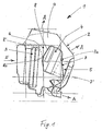
- Fig. 1 shows an air conditioner 1 according to the invention with a housing 2, in which an evaporator 3 and a radiator 4 are arranged one behind the other in the air flow direction. Between the radiator 4 and the housing 2, a first cold air duct 5 and between the radiator 4 and the evaporator 3, a second cold air duct 6 is provided. In the area of the first cold air duct 5, a first mixing flap 7 is pivotably arranged about a pivot axis 7a. The flap 7 takes in the drawing a first extreme position 7 (solid line), in which the cold air duct 5 is closed and the passage of air through the radiator 4 is released.
- the second extreme position 7 ' is shown in dashed lines: in this position, the first cold air duct 5 is fully open and the radiator 4 is blocked for the passage of air.
- a second mixing flap 8 pivotable about an upstream pivot axis 8a, arranged.
- the flap 8 releases the second cold air duct 6 and simultaneously blocks the passage of air from the side of the radiator 4.
- a second dashed extreme position 8 'of the cold air duct 6 is blocked, the air outlet of the Side of the radiator 4, however, open.
- a mixing chamber 9 is arranged, in which open both the first and the second cold air duct 5, 6 as well as coming from the radiator 4 hot air flow.
- the mixing chamber 9 so the air streams of different temperature are mixed to achieve the desired set temperature.
- the air is supplied via channels not shown in a known manner to a passenger compartment of the motor vehicle, not shown.
- the air enters in the flow direction in front of the evaporator 3, indicated by an arrow E, in the housing 2 of the air conditioner 1 and leaves the air conditioner at various points, which are indicated by arrows A.
- Fig. 2 shows the air conditioner of FIG. 1 in a flap position, which should be marked with "100% warm".
- both cold air ducts 5, 6 are closed by the mixing flaps 7, 8 (flap position 7, 8 bold), and the passage of air through the radiator 4 is fully open on both sides.
- the entire air emerging from the evaporator 3 is thus directed by the radiator 4 and heated there maximum.
- the various temperature levels are regulated by the flow rate of a coolant through the radiator 4 via a radiator valve not shown (so-called water-side control).
- the emerging from the radiator 4 hot air flow is indicated by an arrow WL.
- Fig. 3 shows a flap position in which the cold air duct 5 is fully opened and the radiator 4 is blocked for the passage of air.
- the second bypass channel 6 is blocked by the second mixing flap 8.
- This flap position (flap positions 7, 8 bold) is referred to as "100% cold", the cold air flow is indicated by an arrow KL.
- Fig. 4 shows a further flap position (flaps 7, 8 bold), which is referred to as "maximum cold”.
- maximum cold In this flap position both cold air ducts 5, 6 are fully open, and the flow path of the air through the radiator 4 is blocked.
- the exiting from the evaporator 3, maximum cooled air now flows through both cold air ducts 5, 6 around the radiator 4 around in the mixing chamber 9, where both cold air flows, represented by the arrows KL1, KL2, meet.
- KL1, KL2 the mixing chamber, therefore, a mixing of the two cold air flows KL1, KL2 takes place, so that there is also a uniformized air temperature.
- the flow rates of KL1, KL2 set after the respective pressure loss in the two cold air ducts 5, 6 a.
Landscapes
- Physics & Mathematics (AREA)
- Thermal Sciences (AREA)
- Engineering & Computer Science (AREA)
- Mechanical Engineering (AREA)
- Air-Conditioning For Vehicles (AREA)
Abstract
Description
- Fig. 1
- eine erfindungsgemäße Klimaanlage,
- Fig. 2
- die Klimaanlage gemäß Fig. 1 mit einer Klappenstellung "100 % warm",
- Fig. 3
- die Klimaanlage gemäß Fig. 1 mit einer Klappenstellung "100 % kalt" und
- Fig. 4
- die Klimaanlage gemäß Fig. 1 mit einer Klappenstellung "maximal kalt".
Claims (6)
- Klimaanlage, insbesondere für ein Kraftfahrzeug mit in einem Gehäuse (2) angeordnetem Verdampfer (3), Heizkörper (4), Kaltluftkanal (5) und einer Mischklappe (7) zur Regelung einer den Heizkörper (4) und/oder den Kaltluftkanal (5) durchströmenden Luftmenge, dadurch gekennzeichnet, dass ein zweiter durch eine zweite Mischklappe (8) regelbarer Kaltluftkanal (6) vorgesehen ist.
- Klimaanlage nach Anspruch 1, dadurch gekennzeichnet, dass beide Kaltluftkanäle (5, 6) und die aus dem Heizkörper (4) austretende Warmluft (WL) in einen Mischraum (9) münden.
- Klimaanlage nach Anspruch 1 oder 2, dadurch gekennzeichnet, dass der erste Kaltluftkanal (5) zwischen dem Heizkörper (4) und dem Gehäuse (2) und der zweite Kaltluftkanal (6) zwischen dem Heizkörper (4) und dem Verdampfer (3) angeordnet sind.
- Klimaanlage nach Anspruch 1, 2 oder 3, dadurch gekennzeichnet, dass die erste und zweite Mischklappe (7, 8) jeweils zwei Extremlagen, nämlich Kaltluftkanal "auf" und "zu" aufweisen.
- Klimaanlage nach Anspruch 4, dadurch gekennzeichnet, dass bei der Extremlage Kaltluftkanal "auf" eine Luftströmung durch den Heizkörper (4) gesperrt ist.
- Klimaanlage nach einem der Ansprüche 1 bis 5, dadurch gekennzeichnet, dass die erste und die zweite Mischklappe (7, 8) derart miteinander koppelbar sind, dass die zweite Mischklappe (8) nach der ersten Mischklappe (7) schließbar und die Klimaanlage (1) von einer Position "100 % kalt" auf eine Position "maximal kalt" steuerbar ist.
Priority Applications (2)
| Application Number | Priority Date | Filing Date | Title |
|---|---|---|---|
| EP04291367A EP1602513B1 (de) | 2004-06-01 | 2004-06-01 | Klimaanlage, insbesondere für ein Kraftfahrzeug |
| DE200450009268 DE502004009268D1 (de) | 2004-06-01 | 2004-06-01 | Klimaanlage, insbesondere für ein Kraftfahrzeug |
Applications Claiming Priority (1)
| Application Number | Priority Date | Filing Date | Title |
|---|---|---|---|
| EP04291367A EP1602513B1 (de) | 2004-06-01 | 2004-06-01 | Klimaanlage, insbesondere für ein Kraftfahrzeug |
Publications (2)
| Publication Number | Publication Date |
|---|---|
| EP1602513A1 true EP1602513A1 (de) | 2005-12-07 |
| EP1602513B1 EP1602513B1 (de) | 2009-04-01 |
Family
ID=34931137
Family Applications (1)
| Application Number | Title | Priority Date | Filing Date |
|---|---|---|---|
| EP04291367A Expired - Lifetime EP1602513B1 (de) | 2004-06-01 | 2004-06-01 | Klimaanlage, insbesondere für ein Kraftfahrzeug |
Country Status (2)
| Country | Link |
|---|---|
| EP (1) | EP1602513B1 (de) |
| DE (1) | DE502004009268D1 (de) |
Citations (4)
| Publication number | Priority date | Publication date | Assignee | Title |
|---|---|---|---|---|
| US4593852A (en) * | 1983-12-29 | 1986-06-10 | Nihon Radiator Co., Ltd. | Air conditioner for automobile |
| EP0212306A2 (de) * | 1985-08-16 | 1987-03-04 | Adam Opel Aktiengesellschaft | Heiz- und Belüftungseinrichtung für Kraftfahrzeuge |
| DE10104907A1 (de) | 2001-02-03 | 2002-08-08 | Behr Gmbh & Co | Klimagerät für ein Kraftfahrzeug |
| US20030230103A1 (en) * | 2000-03-13 | 2003-12-18 | Zexel Valeo Climate Control Corporation | Automotive air conditioner and instrument panel module |
Family Cites Families (1)
| Publication number | Priority date | Publication date | Assignee | Title |
|---|---|---|---|---|
| JPS59124719U (ja) * | 1982-09-30 | 1984-08-22 | カルソニックカンセイ株式会社 | インテ−クユニツト |
-
2004
- 2004-06-01 EP EP04291367A patent/EP1602513B1/de not_active Expired - Lifetime
- 2004-06-01 DE DE200450009268 patent/DE502004009268D1/de not_active Expired - Lifetime
Patent Citations (4)
| Publication number | Priority date | Publication date | Assignee | Title |
|---|---|---|---|---|
| US4593852A (en) * | 1983-12-29 | 1986-06-10 | Nihon Radiator Co., Ltd. | Air conditioner for automobile |
| EP0212306A2 (de) * | 1985-08-16 | 1987-03-04 | Adam Opel Aktiengesellschaft | Heiz- und Belüftungseinrichtung für Kraftfahrzeuge |
| US20030230103A1 (en) * | 2000-03-13 | 2003-12-18 | Zexel Valeo Climate Control Corporation | Automotive air conditioner and instrument panel module |
| DE10104907A1 (de) | 2001-02-03 | 2002-08-08 | Behr Gmbh & Co | Klimagerät für ein Kraftfahrzeug |
Also Published As
| Publication number | Publication date |
|---|---|
| EP1602513B1 (de) | 2009-04-01 |
| DE502004009268D1 (de) | 2009-05-14 |
Similar Documents
| Publication | Publication Date | Title |
|---|---|---|
| EP0841201B1 (de) | Heiz- oder Klimaanlage für ein Kraftfahrzeug | |
| DE102009057814B4 (de) | Klimaanlage für Fahrzeuge | |
| DE60200264T2 (de) | Kraftfahrzeugklimaanlage | |
| EP0102611B1 (de) | Heiz- und/oder Klimaanlage für Kraftfahrzeuge | |
| EP1134102B1 (de) | Heizungs- oder Klimaanlage | |
| DE29504860U1 (de) | Nach dem Mischluftprinzip arbeitendes Heiz- bzw. Klimagerät | |
| DE10057039A1 (de) | Heizungs- oder Klimaanlage für ein Kraftfahrzeug | |
| DE19749104B4 (de) | Fahrzeug-Klimaanlage | |
| DE102007014835B4 (de) | Fahrzeugklimaanlage | |
| DE3046336A1 (de) | Fahrzeug-klimaanlage | |
| DE19750381B4 (de) | Kraftfahrzeug-Klimaanlage | |
| DE3514359A1 (de) | Vorrichtung zum beheizen und/oder klimatisieren des innenraums eines fahrzeuges | |
| DE102011008520B4 (de) | Klimaanlage zur Steuerung eines Luftstroms in einer Klimaanlage eines Fahrzeugs | |
| DE10051195A1 (de) | Fahrzeugklimaanlage mit seitlicher Kopfraum-Öffnung | |
| DE102018207369A1 (de) | Klimaanlage mit mehreren stromab einer Heizeinrichtung angeordneten Temperaturregelungsklappen | |
| DE112014005711T5 (de) | Vorrichtung zur thermischen Behandlung eines Fahrgastraums und/oder eines Organs eines Kraftfahrzeugs | |
| EP1510375B1 (de) | Klimaanlage sowie Verfahren zum Betreiben einer solchen | |
| DE19807002A1 (de) | Klimaanlage für ein Fahrzeug | |
| DE102015122348A1 (de) | Heiz- und Klimaanlage für ein Kraftfahrzeug | |
| DE10045438A1 (de) | Klimaanlage für ein Kraftfahrzeug | |
| EP1602513B1 (de) | Klimaanlage, insbesondere für ein Kraftfahrzeug | |
| DE10337195A1 (de) | Luftkonditionierungseinrichtung, insbesondere Heizungs- oder Klimaanlage, für Fahrzeuge | |
| EP2277728B1 (de) | Klimaanlage | |
| DE102004030672B4 (de) | V-förmige Wärmetauscheranordnung einer Heiz-Klimaanlage | |
| EP1641644B1 (de) | Klimatisierungseinrichtung für fahrzeuge sowie verfahren zum betreiben einer klimatisierungseinrichtung |
Legal Events
| Date | Code | Title | Description |
|---|---|---|---|
| PUAI | Public reference made under article 153(3) epc to a published international application that has entered the european phase |
Free format text: ORIGINAL CODE: 0009012 |
|
| AK | Designated contracting states |
Kind code of ref document: A1 Designated state(s): AT BE BG CH CY CZ DE DK EE ES FI FR GB GR HU IE IT LI LU MC NL PL PT RO SE SI SK TR |
|
| AX | Request for extension of the european patent |
Extension state: AL HR LT LV MK |
|
| 17P | Request for examination filed |
Effective date: 20060607 |
|
| AKX | Designation fees paid |
Designated state(s): CZ DE FR IT |
|
| 17Q | First examination report despatched |
Effective date: 20061005 |
|
| 17Q | First examination report despatched |
Effective date: 20061005 |
|
| GRAP | Despatch of communication of intention to grant a patent |
Free format text: ORIGINAL CODE: EPIDOSNIGR1 |
|
| GRAS | Grant fee paid |
Free format text: ORIGINAL CODE: EPIDOSNIGR3 |
|
| GRAA | (expected) grant |
Free format text: ORIGINAL CODE: 0009210 |
|
| AK | Designated contracting states |
Kind code of ref document: B1 Designated state(s): CZ DE FR IT |
|
| REF | Corresponds to: |
Ref document number: 502004009268 Country of ref document: DE Date of ref document: 20090514 Kind code of ref document: P |
|
| PG25 | Lapsed in a contracting state [announced via postgrant information from national office to epo] |
Ref country code: CZ Free format text: LAPSE BECAUSE OF FAILURE TO SUBMIT A TRANSLATION OF THE DESCRIPTION OR TO PAY THE FEE WITHIN THE PRESCRIBED TIME-LIMIT Effective date: 20090401 |
|
| PLBE | No opposition filed within time limit |
Free format text: ORIGINAL CODE: 0009261 |
|
| STAA | Information on the status of an ep patent application or granted ep patent |
Free format text: STATUS: NO OPPOSITION FILED WITHIN TIME LIMIT |
|
| 26N | No opposition filed |
Effective date: 20100105 |
|
| PG25 | Lapsed in a contracting state [announced via postgrant information from national office to epo] |
Ref country code: IT Free format text: LAPSE BECAUSE OF FAILURE TO SUBMIT A TRANSLATION OF THE DESCRIPTION OR TO PAY THE FEE WITHIN THE PRESCRIBED TIME-LIMIT Effective date: 20090401 |
|
| REG | Reference to a national code |
Ref country code: DE Ref legal event code: R082 Ref document number: 502004009268 Country of ref document: DE Representative=s name: GRAUEL, ANDREAS, DIPL.-PHYS. DR. RER. NAT., DE Ref country code: DE Ref legal event code: R081 Ref document number: 502004009268 Country of ref document: DE Owner name: MAHLE INTERNATIONAL GMBH, DE Free format text: FORMER OWNER: BEHR FRANCE ROUFFACH S.A.S., ROUFFACH, FR |
|
| REG | Reference to a national code |
Ref country code: FR Ref legal event code: PLFP Year of fee payment: 13 |
|
| REG | Reference to a national code |
Ref country code: FR Ref legal event code: PLFP Year of fee payment: 14 |
|
| REG | Reference to a national code |
Ref country code: FR Ref legal event code: PLFP Year of fee payment: 15 |
|
| PGFP | Annual fee paid to national office [announced via postgrant information from national office to epo] |
Ref country code: FR Payment date: 20190625 Year of fee payment: 16 |
|
| PGFP | Annual fee paid to national office [announced via postgrant information from national office to epo] |
Ref country code: DE Payment date: 20190822 Year of fee payment: 16 |
|
| REG | Reference to a national code |
Ref country code: DE Ref legal event code: R119 Ref document number: 502004009268 Country of ref document: DE |
|
| PG25 | Lapsed in a contracting state [announced via postgrant information from national office to epo] |
Ref country code: FR Free format text: LAPSE BECAUSE OF NON-PAYMENT OF DUE FEES Effective date: 20200630 |
|
| PG25 | Lapsed in a contracting state [announced via postgrant information from national office to epo] |
Ref country code: DE Free format text: LAPSE BECAUSE OF NON-PAYMENT OF DUE FEES Effective date: 20210101 |