EP1602153B1 - Metal foaming material contact for electrical connections - Google Patents
Metal foaming material contact for electrical connections Download PDFInfo
- Publication number
- EP1602153B1 EP1602153B1 EP03786039A EP03786039A EP1602153B1 EP 1602153 B1 EP1602153 B1 EP 1602153B1 EP 03786039 A EP03786039 A EP 03786039A EP 03786039 A EP03786039 A EP 03786039A EP 1602153 B1 EP1602153 B1 EP 1602153B1
- Authority
- EP
- European Patent Office
- Prior art keywords
- foam
- contact
- electrical
- copper
- connection
- Prior art date
- Legal status (The legal status is an assumption and is not a legal conclusion. Google has not performed a legal analysis and makes no representation as to the accuracy of the status listed.)
- Expired - Lifetime
Links
- 239000000463 material Substances 0.000 title abstract description 4
- 229910052751 metal Inorganic materials 0.000 title description 2
- 239000002184 metal Substances 0.000 title description 2
- 238000005187 foaming Methods 0.000 title 1
- 239000004020 conductor Substances 0.000 claims abstract description 18
- 229920001971 elastomer Polymers 0.000 claims abstract 2
- 239000006260 foam Substances 0.000 claims description 39
- 239000006262 metallic foam Substances 0.000 claims description 9
- BQCADISMDOOEFD-UHFFFAOYSA-N Silver Chemical group [Ag] BQCADISMDOOEFD-UHFFFAOYSA-N 0.000 claims description 5
- 229910052709 silver Inorganic materials 0.000 claims description 5
- 239000004332 silver Substances 0.000 claims description 5
- 239000003795 chemical substances by application Substances 0.000 claims description 4
- 230000004888 barrier function Effects 0.000 claims description 3
- 238000007789 sealing Methods 0.000 claims description 2
- 238000000151 deposition Methods 0.000 claims 1
- 239000000806 elastomer Substances 0.000 claims 1
- 230000037431 insertion Effects 0.000 abstract 2
- 238000003780 insertion Methods 0.000 abstract 2
- RYGMFSIKBFXOCR-UHFFFAOYSA-N Copper Chemical compound [Cu] RYGMFSIKBFXOCR-UHFFFAOYSA-N 0.000 description 34
- 229910052802 copper Inorganic materials 0.000 description 33
- 239000010949 copper Substances 0.000 description 33
- 229910052782 aluminium Inorganic materials 0.000 description 8
- XAGFODPZIPBFFR-UHFFFAOYSA-N aluminium Chemical compound [Al] XAGFODPZIPBFFR-UHFFFAOYSA-N 0.000 description 8
- 230000015556 catabolic process Effects 0.000 description 8
- 238000006731 degradation reaction Methods 0.000 description 8
- 230000002093 peripheral effect Effects 0.000 description 5
- 230000000694 effects Effects 0.000 description 4
- HEMHJVSKTPXQMS-UHFFFAOYSA-M Sodium hydroxide Chemical compound [OH-].[Na+] HEMHJVSKTPXQMS-UHFFFAOYSA-M 0.000 description 3
- 229910000831 Steel Inorganic materials 0.000 description 3
- NEIHULKJZQTQKJ-UHFFFAOYSA-N [Cu].[Ag] Chemical compound [Cu].[Ag] NEIHULKJZQTQKJ-UHFFFAOYSA-N 0.000 description 3
- 230000000593 degrading effect Effects 0.000 description 3
- 238000009826 distribution Methods 0.000 description 3
- 238000005868 electrolysis reaction Methods 0.000 description 3
- 238000012423 maintenance Methods 0.000 description 3
- 238000000034 method Methods 0.000 description 3
- 230000009467 reduction Effects 0.000 description 3
- 239000010959 steel Substances 0.000 description 3
- 241000195940 Bryophyta Species 0.000 description 2
- 235000011929 mousse Nutrition 0.000 description 2
- 230000008569 process Effects 0.000 description 2
- 238000009628 steelmaking Methods 0.000 description 2
- XLYOFNOQVPJJNP-UHFFFAOYSA-N water Substances O XLYOFNOQVPJJNP-UHFFFAOYSA-N 0.000 description 2
- QPLDLSVMHZLSFG-UHFFFAOYSA-N Copper oxide Chemical compound [Cu]=O QPLDLSVMHZLSFG-UHFFFAOYSA-N 0.000 description 1
- 239000005751 Copper oxide Substances 0.000 description 1
- 101001126084 Homo sapiens Piwi-like protein 2 Proteins 0.000 description 1
- 102100029365 Piwi-like protein 2 Human genes 0.000 description 1
- GYMWQLRSSDFGEQ-ADRAWKNSSA-N [(3e,8r,9s,10r,13s,14s,17r)-13-ethyl-17-ethynyl-3-hydroxyimino-1,2,6,7,8,9,10,11,12,14,15,16-dodecahydrocyclopenta[a]phenanthren-17-yl] acetate;(8r,9s,13s,14s,17r)-17-ethynyl-13-methyl-7,8,9,11,12,14,15,16-octahydro-6h-cyclopenta[a]phenanthrene-3,17-diol Chemical compound OC1=CC=C2[C@H]3CC[C@](C)([C@](CC4)(O)C#C)[C@@H]4[C@@H]3CCC2=C1.O/N=C/1CC[C@@H]2[C@H]3CC[C@](CC)([C@](CC4)(OC(C)=O)C#C)[C@@H]4[C@@H]3CCC2=C\1 GYMWQLRSSDFGEQ-ADRAWKNSSA-N 0.000 description 1
- 239000003513 alkali Substances 0.000 description 1
- PNEYBMLMFCGWSK-UHFFFAOYSA-N aluminium oxide Inorganic materials [O-2].[O-2].[O-2].[Al+3].[Al+3] PNEYBMLMFCGWSK-UHFFFAOYSA-N 0.000 description 1
- 239000003990 capacitor Substances 0.000 description 1
- 238000004140 cleaning Methods 0.000 description 1
- 230000000052 comparative effect Effects 0.000 description 1
- 150000001879 copper Chemical class 0.000 description 1
- 229910000431 copper oxide Inorganic materials 0.000 description 1
- 238000002788 crimping Methods 0.000 description 1
- 230000007423 decrease Effects 0.000 description 1
- 238000004870 electrical engineering Methods 0.000 description 1
- 230000007613 environmental effect Effects 0.000 description 1
- 239000003344 environmental pollutant Substances 0.000 description 1
- 230000004927 fusion Effects 0.000 description 1
- 230000006872 improvement Effects 0.000 description 1
- 238000009830 intercalation Methods 0.000 description 1
- 230000002427 irreversible effect Effects 0.000 description 1
- 239000007788 liquid Substances 0.000 description 1
- 238000003754 machining Methods 0.000 description 1
- 150000002739 metals Chemical class 0.000 description 1
- 230000035515 penetration Effects 0.000 description 1
- 230000000704 physical effect Effects 0.000 description 1
- 231100000719 pollutant Toxicity 0.000 description 1
- 238000005096 rolling process Methods 0.000 description 1
- 239000000565 sealant Substances 0.000 description 1
- 125000006850 spacer group Chemical group 0.000 description 1
- 238000005406 washing Methods 0.000 description 1
Images
Classifications
-
- H—ELECTRICITY
- H01—ELECTRIC ELEMENTS
- H01R—ELECTRICALLY-CONDUCTIVE CONNECTIONS; STRUCTURAL ASSOCIATIONS OF A PLURALITY OF MUTUALLY-INSULATED ELECTRICAL CONNECTING ELEMENTS; COUPLING DEVICES; CURRENT COLLECTORS
- H01R13/00—Details of coupling devices of the kinds covered by groups H01R12/70 or H01R24/00 - H01R33/00
- H01R13/02—Contact members
- H01R13/03—Contact members characterised by the material, e.g. plating, or coating materials
-
- H—ELECTRICITY
- H01—ELECTRIC ELEMENTS
- H01R—ELECTRICALLY-CONDUCTIVE CONNECTIONS; STRUCTURAL ASSOCIATIONS OF A PLURALITY OF MUTUALLY-INSULATED ELECTRICAL CONNECTING ELEMENTS; COUPLING DEVICES; CURRENT COLLECTORS
- H01R4/00—Electrically-conductive connections between two or more conductive members in direct contact, i.e. touching one another; Means for effecting or maintaining such contact; Electrically-conductive connections having two or more spaced connecting locations for conductors and using contact members penetrating insulation
- H01R4/28—Clamped connections, spring connections
- H01R4/30—Clamped connections, spring connections utilising a screw or nut clamping member
- H01R4/304—Clamped connections, spring connections utilising a screw or nut clamping member having means for improving contact
-
- H—ELECTRICITY
- H01—ELECTRIC ELEMENTS
- H01R—ELECTRICALLY-CONDUCTIVE CONNECTIONS; STRUCTURAL ASSOCIATIONS OF A PLURALITY OF MUTUALLY-INSULATED ELECTRICAL CONNECTING ELEMENTS; COUPLING DEVICES; CURRENT COLLECTORS
- H01R4/00—Electrically-conductive connections between two or more conductive members in direct contact, i.e. touching one another; Means for effecting or maintaining such contact; Electrically-conductive connections having two or more spaced connecting locations for conductors and using contact members penetrating insulation
- H01R4/28—Clamped connections, spring connections
- H01R4/30—Clamped connections, spring connections utilising a screw or nut clamping member
- H01R4/34—Conductive members located under head of screw
-
- Y—GENERAL TAGGING OF NEW TECHNOLOGICAL DEVELOPMENTS; GENERAL TAGGING OF CROSS-SECTIONAL TECHNOLOGIES SPANNING OVER SEVERAL SECTIONS OF THE IPC; TECHNICAL SUBJECTS COVERED BY FORMER USPC CROSS-REFERENCE ART COLLECTIONS [XRACs] AND DIGESTS
- Y10—TECHNICAL SUBJECTS COVERED BY FORMER USPC
- Y10S—TECHNICAL SUBJECTS COVERED BY FORMER USPC CROSS-REFERENCE ART COLLECTIONS [XRACs] AND DIGESTS
- Y10S439/00—Electrical connectors
- Y10S439/927—Conductive gasket
Definitions
- the present invention relates to devices for improving and increasing the conductance of electrical connections and particularly relates to a contact device for improving the service life of electrical connections.
- the maintenance of the connections requires disassembly to practice a re-surfacing of the areas in contact.
- the tools used for these re-surfacing are generally rotary grinding machines. They degrade the total flatness of the surfaces in contact which has the effect of limiting areas and points of contact. The contact areas being reduced, the connections then undergo electrical stresses concentrated on these areas and their degradation is even faster.
- JA-A-530805890n discloses a metal foam spacer for improving the conductivity of the connection in a capacitor. But this element is not suitable in the context of the invention which relates to the case of connections in which continuous currents of high intensity exceeding 1000 A.
- the first object of the invention is to provide a contact device for electrical connections in order to improve the electrical conductance of these connections and to slow the degradation of the surfaces in contact.
- Another object of the invention is to provide a contact device for improving the electrical connections in order to increase the electrical performance of these connections when they are in an advanced state of degradation.
- a third object of the invention is to provide a contact device for improving the electrical connections subjected to currents of high intensity greater than 1000 A, to increase the electrical performance of these connections.
- the object of the invention is therefore a contact device essentially comprising a conductive element adapted to be interposed between the two contact surfaces of two conductors of an electrical connection.
- the intermediate conductive element in which circulates a current of an intensity greater than 1000 A is made of silver foam of high porosity and deformability to reduce the electrical resistance of the connection. It also includes minus a peripheral seal creating a seal-proof barrier to external degrading agents at the periphery of the intercalating conductive element.
- the intermediate conductive element used in the device according to the invention is a metal foam 10 preferably manufactured according to the method described in the patent application.
- WO 02/059396 it being understood that the device according to the invention is not limited to metal foams obtained by the process described in this document.
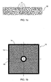
- the metal foam is preferably a copper foam. Its structure is alveolar and its physical properties are mainly a high porosity and deformability and a low density of the order of 400g / m 2 . In comparison, the density of a copper sheet of the same thickness is of the order of 15 kg / m 2 .
- the honeycomb structure of the copper foam is such that it consists for the most part of vacuum.
- its surface comprises a multitude of contact points 11 of the order of one micron, the number of which reaches 30 points per mm 2 .
- the thickness of the copper foam is of the order of 2 mm.
- this copper foam constituting the intermediate conductive element according to the invention is cut to the size of the contact surface of the electrical connection described in FIG. figure 2 and has an opening 18 for the passage of the clamping bolt.
- the copper foam thus cut has two peripheral sealing seals 14 and 16.
- Peripheral seals 14 and 16 may be made in different ways. They may be impregnated in the foam or made by the removal of an elastomeric sealant on the periphery. But it is also possible to make joints by folding the edges of the foam plate at least once on itself or by rolling the edges of the foam plate.
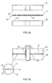
- FIGs 2a and 2b represent an electrical connection according to the invention.
- the conductors 21 and 23 are located on either side of the copper foam 10 so that their surfaces 22 and 24 come into contact with the copper foam.
- the copper foam is an intermediate element between the two conductors of the electrical connection.
- the electrical connection between the conductors 21 and 23 is made by close contact by means of a clamping means such as a clamping bolt 25 passing through the two conductors through a hole provided for this purpose and through the opening 18 of the foam of copper 10.
- the device according to the invention can be used for a contact of a new electrical connection.
- it improves the homogeneity of the passage of the current through the surface in contact.
- the contact is even more important that it is located near the clamping means or clamping bolt 25. Therefore, the resistance and therefore the electrical losses of the electrical connection consisting of the conductors 21 and 23 in contact is minimal near the clamping means .25 and increases more away from it.
- This inhomogeneous distribution of the current favors a zone of higher current concentration and therefore a zone more solicited and therefore degraded-more-quickly.
- the provision of the intermediate conductive element made of copper foam increases the points of contact between the two conductors 21 and 23 and thus allows a homogeneous distribution of the current over the entire contact surface. Thanks to this homogeneous distribution, there are no areas of concentration of current so no areas more solicited and conducive to a faster degradation.
- the device according to the invention can also be advantageously used for a contact of a degraded or deformed electrical connection.
- the conductors and the electrical connections are subjected to currents of high intensity and high temperatures.
- the wear of the connections is concretized mainly by a deformation of the contact surfaces of the electrical connections. This results in significant electrical losses of up to several KW per connection and variations in the flow of current through these contacting surfaces.
- the re-machining of deformed contact surfaces is no longer necessary thanks to the contribution of copper foam. There is thus obtained a significant improvement in the electrical connections having degraded and deformed contact surfaces 22 and 24, even in the case of deformations of the order of one millimeter.
- the deformability of the copper foam allows the whole of the foam 10 to marry the degraded contours of the surfaces in contact 22 and 24, as described on the enlargement of the figure 2b and thus to increase the contact area and distribute the pressure exerted through the clamping means 25.
- the tips 11 on the surface of the copper foam multiply the points of contact. This results in improved current flow conditions by reducing electrical losses.
- the tips 11 on the surface of the copper foam also pierce the oxide layers that appear on the surface of the metals and therefore the conductors 21 and 23, such as copper oxide or alumina for example. 'aluminum. These layers have an insulating effect and act as resistors and therefore induce electrical losses.
- the device according to the invention makes it possible to improve the electrical conductance of a used connection even without first cleaning it.
- the peripheral seal 14 and 16 makes it possible to reduce the penetration of degrading external agents into the connection by creating a sealed barrier at the periphery of the connection.
- the degrading agents are generally liquids such as sodium hydroxide or washing water or any other pollutant product transported by water.
- Copper foam can be improved by removing a product that improves heat transfer and electrical conductivity.
- the use of a silver-plated copper foam as an intermediate conductive element improves the efficiency of the device according to the invention.
- the potential drop of a connection of 1 dm 2 formed of two copper conductors is of the order of 50 mV for a current of an intensity of 5000 A.
- the potential drop decreases to 26 mV and with a silver copper foam, the potential drop is only 5 mV for identical temperature and pressure conditions in all three cases.
- the silver is deposited on the copper foam by a conventional electrochemical process or under vacuum.
- the device according to the invention is all the more advantageous, it sees its efficiency increase with temperature. Indeed, the potential drop of a 1 dm 2 connection using the device according to the invention with a silver copper foam is of the order of a few mV for a current of an intensity of 5000 A and the temperature of 300 ° C. This feature is due to the fact that the tips 11 of the metal foam (copper, silver copper or silver) are soldered under the effect of temperature to the conductors 21 and 23 with which they are in contact.
- metal foam is preferably used for the practice of the invention, any other conductive foam composed of one or more materials could be used.
- the device according to the invention has many other advantages. Its implementation is fast, easy and clean. It is particularly advantageous for improving the conductance of copper / copper electrical connections but also for connections between two different electrical conductors such as aluminum / copper or steel / aluminum or steel / copper pairs.
- the device according to the present invention makes it possible to slow down the degradation of the surface state of the electrical connections subjected to currents of high intensity.
- the use of the copper foam according to the invention is also conceivable to improve the thermal conductance of contact and thus avoid thermal losses due to the passage of heat from one material to another.
Landscapes
- Connections Effected By Soldering, Adhesion, Or Permanent Deformation (AREA)
- Contacts (AREA)
- Powder Metallurgy (AREA)
- Non-Insulated Conductors (AREA)
- Conductive Materials (AREA)
- Push-Button Switches (AREA)
- Coupling Device And Connection With Printed Circuit (AREA)
Abstract
Description
La présente invention concerne les dispositifs d'amélioration et d'augmentation de la conductance des connexions électriques et concerne en particulier un dispositif de contact pour améliorer la durée de vie des connexions électriques.The present invention relates to devices for improving and increasing the conductance of electrical connections and particularly relates to a contact device for improving the service life of electrical connections.
Dans le domaine de l'électrotechnique de puissance, les connexions électriques des cuves d'électrolyse ou des fours d'aciérie sont soumises à des courants de haute intensité (I > 1000 A) et à des températures élevées. Il en résulte des pertes électriques importantes pouvant atteindre plusieurs KW par connexion et la perte de rendement qui en découle est un problème majeur. La dégradation de ces connexions est irréversible. En effet, la dégradation des surfaces en contact induit des variations de la densité du courant à travers cette surface. Il s'ensuit des pertes électriques par effet Joule et par la même une augmentation des températures ce qui accélère la dégradation des connexions mais également des conducteurs et peut même entraîner leur fusion.In the field of power electrical engineering, the electrical connections of electrolysis tanks or steelmaking furnaces are subjected to currents of high intensity (I> 1000 A) and at high temperatures. This results in significant electrical losses of up to several KW per connection and the resulting loss of efficiency is a major problem. The degradation of these connections is irreversible. Indeed, the degradation of the surfaces in contact induces variations in the density of the current through this surface. It follows electric losses by Joule effect and by the same an increase in temperatures which accelerates the degradation of the connections but also the drivers and can even lead to their fusion.
La maintenance des connexions nécessite de les démonter afin de pratiquer un re-surfaçage des zones en contact. Les outils employés pour ces re-surfaçages sont en général des disqueuses rotatives. Elles dégradent la planéité totale des surfaces en contact ce qui a pour conséquence de limiter les zones et les points de contact. Les zones de contact étant réduites, les connexions subissent alors des contraintes électriques concentrées sur ces zones et leur dégradation est encore plus rapide.The maintenance of the connections requires disassembly to practice a re-surfacing of the areas in contact. The tools used for these re-surfacing are generally rotary grinding machines. They degrade the total flatness of the surfaces in contact which has the effect of limiting areas and points of contact. The contact areas being reduced, the connections then undergo electrical stresses concentrated on these areas and their degradation is even faster.
Pour retrouver les surfaces de contact des connexions d'origine, le démontage total des connexions est nécessaire afin de ré-usiner sur machine les surfaces de contact. Mais cette opération est lourde et coûteuse.To recover the contact surfaces of the original connections, the total disassembly of the connections is necessary to re-machine the contact surfaces. But this operation is heavy and expensive.
Le document JA-A-530805890n décrit un élément intercalaire en mousse de métal destiné à améliorer la conductivité de la connexion dans un condensateur. Mais cet élément n'est pas adapté dans le cadre de l'invention qui concerne le cas des connexions où circulent des courants continus de forte intensité dépassant 1000 A.JA-A-530805890n discloses a metal foam spacer for improving the conductivity of the connection in a capacitor. But this element is not suitable in the context of the invention which relates to the case of connections in which continuous currents of high intensity exceeding 1000 A.
A noter que le document
C'est pourquoi le premier but de l'invention est de fournir un dispositif de contact pour connexions électriques afin d'améliorer la conductance électrique de ces connexions et de ralentir la dégradation des surfaces en contact.This is why the first object of the invention is to provide a contact device for electrical connections in order to improve the electrical conductance of these connections and to slow the degradation of the surfaces in contact.
Un autre but de l'invention est de fournir un dispositif de contact pour améliorer les connexions électriques afin d'augmenter les performances électriques de ces connexions lorsqu'elles sont dans un état de dégradation avancée.Another object of the invention is to provide a contact device for improving the electrical connections in order to increase the electrical performance of these connections when they are in an advanced state of degradation.
Un troisième but dé l'invention est de fournir un dispositif de contact pour améliorer les connexions électriques soumises à des courants de haute intensité supérieur à 1000 A, afin d'augmenter les performances électriques de ces connexions.A third object of the invention is to provide a contact device for improving the electrical connections subjected to currents of high intensity greater than 1000 A, to increase the electrical performance of these connections.
L'objet de l'invention est donc un dispositif de contact comprenant essentiellement un élément conducteur adapté pour être intercalé entre les deux surfaces de contact de deux conducteurs d'une connexion électrique. L'élément conducteur intercalaire dans lequel circule un courant d'une intensité supérieure à 1000 A est constitué de mousse d'argent de porosité et de déformabilité élevées afin de réduire la résistance électrique de la connexion. Il comporte en outre au moins un joint d'étanchéité périphérique créant une barrière étanche aux agents extérieurs dégradants à la périphérie de l'élément conducteur intercalaire.The object of the invention is therefore a contact device essentially comprising a conductive element adapted to be interposed between the two contact surfaces of two conductors of an electrical connection. The intermediate conductive element in which circulates a current of an intensity greater than 1000 A is made of silver foam of high porosity and deformability to reduce the electrical resistance of the connection. It also includes minus a peripheral seal creating a seal-proof barrier to external degrading agents at the periphery of the intercalating conductive element.
Les buts, objets et caractéristiques de l'invention apparaîtront plus clairement à la lecture de la description qui suit faite en référence aux dessins dans lesquels :
- La figure la représente de façon microscopique une coupe transversale de la mousse de cuivre,
- La
figure 1b représente une plaque de la mousse de cuivre selon un mode de réalisation de l'invention, - La
figure 2a représente une coupe de la connexion électrique selon l'invention avant le serrage, - La
figure 2b représente une coupe de la connexion électrique selon l'invention.
- Figure la shows a microscopic cross-section of the copper foam,
- The
figure 1b represents a plate of the copper foam according to one embodiment of the invention, - The
figure 2a represents a section of the electrical connection according to the invention before tightening, - The
figure 2b represents a section of the electrical connection according to the invention.
En référence à la
Selon la
Selon un des modes de réalisation de l'invention, cette mousse de cuivre constituant l'élément conducteur intercalaire selon l'invention est découpée à la taille de la surface de contact de la connexion électrique décrite dans la
Les
Le dispositif selon l'invention peut être utilisé pour un contact d'une connexion électrique neuve. Dans ce cas, il améliore l'homogénéité du passage du courant à travers la surface en contact. En effet, dans une connexion électrique représentée par exemple par les deux conducteurs 21 et 23 en contact l'un avec l'autre, le contact est d'autant plus important qu'il se situe à proximité du moyen de serrage ou boulon de serrage 25. Par conséquent, la résistance et donc les pertes électriques de la connexion électrique constituée des conducteurs 21 et 23 en contact est minimale près du moyen de serrage .25 et augmente plus on s'en éloigne. Cette répartition inhomogène du courant favorise une zone de concentration de courant plus élevé et donc une zone davantage sollicitée et donc dégradée-plus-rapidement. L'apport de l'élément conducteur intercalaire constitué de mousse de cuivre augmente les points de contacts entre les deux conducteurs 21 et 23 et permet donc une répartition homogène du courant sur toute la surface de contact. Grâce à cette répartition homogène, il n'existe pas de zones de concentration de courant donc pas de zones davantage sollicitées et propices à une dégradation plus rapide.The device according to the invention can be used for a contact of a new electrical connection. In this case, it improves the homogeneity of the passage of the current through the surface in contact. Indeed, in an electrical connection represented for example by the two
Le dispositif selon l'invention peut également être avantageusement utilisé pour un contact d'une connexion électrique dégradée ou déformée. Dans le domaine des cuves d'électrolyse et des fours d'aciérie, les conducteurs et les connexions électriques sont soumis à des courants de haute intensité et à des températures élevées. L'usure des connexions se concrétise principalement par une déformation des surfaces de contact des connexions électriques. Il en résulte des pertes électriques importantes pouvant atteindre plusieurs KW par connexion et des variations du passage de courant à travers ces surfaces en contact. Le ré-usinage des surfaces de contact déformées n'est plus nécessaire grâce à l'apport de mousse de cuivre. On obtient ainsi une amélioration importante des connexions électriques présentant des surfaces de contact 22 et 24 dégradées et déformées, même lorsqu'il s'agit de déformations de l'ordre du millimètre. En effet, la déformabilité de la mousse de cuivre permet à l'ensemble de la mousse 10 d'épouser les contours dégradés des surfaces en contact 22 et 24, tel qu'il est décrit sur l'agrandissement de la
Le joint d'étanchéité périphérique 14 et 16 permet de réduire la pénétration d'agents extérieurs dégradants dans la connexion en créant une barrière étanche à la périphérie de la connexion. En effet, et en particulier dans le cas des cuves d'électrolyse chlore-soude, les agents dégradants sont généralement des liquides tels que de la soude ou de l'eau de lavage ou bien tout autre produit polluant transporté par l'eau.The
La mousse de cuivre peut être améliorée par la dépose d'un produit améliorant le transfert thermique et la conductivité électrique. Ainsi, l'utilisation d'une mousse de cuivre argenté comme élément conducteur intercalaire améliore l'efficacité du dispositif selon l'invention. En effet, la chute de potentiel d'une connexion de 1 dm2 formée de deux conducteurs en cuivre est de l'ordre de 50 mV pour un courant d'une intensité de 5000 A. Avec une mousse de cuivre, la chute de potentiel diminue à 26 mV et avec une mousse de cuivre argentée, la chute de potentiel n'est plus que 5 mV pour des conditions de température et de pression identiques dans les trois cas. L'argent est déposé sur la mousse de cuivre par un procédé électrochimique classique ou sous vide.Copper foam can be improved by removing a product that improves heat transfer and electrical conductivity. Thus, the use of a silver-plated copper foam as an intermediate conductive element improves the efficiency of the device according to the invention. Indeed, the potential drop of a connection of 1 dm 2 formed of two copper conductors is of the order of 50 mV for a current of an intensity of 5000 A. With a copper foam, the potential drop decreases to 26 mV and with a silver copper foam, the potential drop is only 5 mV for identical temperature and pressure conditions in all three cases. The silver is deposited on the copper foam by a conventional electrochemical process or under vacuum.
L'utilisation d'un élément conducteur intercalaire composé d'une mousse d'argent est également possible sans sortir du cadre de l'invention.The use of an interposed conductive element composed of a silver foam is also possible without departing from the scope of the invention.
Le dispositif selon l'invention est d'autant plus avantageux, qu'il voit son efficacité augmenter avec la température. En effet, la chute de potentiel d'une connexion de 1 dm2 utilisant le dispositif selon l'invention avec une mousse de cuivre argentée est de- l'ordre de-quelques mV pour un courant d'une intensité de 5000 A et à la température de 300°C. Cette particularité est due au fait que les pointes 11 de la mousse métallique (de cuivre, de cuivre argenté ou d'argent) se soudent sous l'effet de la température aux conducteurs 21 et 23 avec lesquels elles sont en contact.The device according to the invention is all the more advantageous, it sees its efficiency increase with temperature. Indeed, the potential drop of a 1 dm 2 connection using the device according to the invention with a silver copper foam is of the order of a few mV for a current of an intensity of 5000 A and the temperature of 300 ° C. This feature is due to the fact that the
Bien que la mousse de métal soit utilisée de préférence pour la mise en oeuvre de l'invention, tout autre mousse conductrice composée d'un ou plusieurs matériaux pourrait être utilisée.Although the metal foam is preferably used for the practice of the invention, any other conductive foam composed of one or more materials could be used.
Le dispositif selon l'invention présente de nombreux autres avantages. Sa mise en oeuvre est rapide, facile et propre. Il est particulièrement avantageux pour améliorer la conductance des connexions électriques cuivre/cuivre mais également des connexions entre deux conducteurs électriques différents tels que les couples aluminium/cuivre ou acier/aluminium ou acier/cuivre.The device according to the invention has many other advantages. Its implementation is fast, easy and clean. It is particularly advantageous for improving the conductance of copper / copper electrical connections but also for connections between two different electrical conductors such as aluminum / copper or steel / aluminum or steel / copper pairs.
Par la diminution des pertes électriques qu'il induit, le dispositif selon la présente invention, permet de ralentir la dégradation de l'état de surface des connexions électriques soumises à des courants de haute intensité.By reducing the electrical losses it induces, the device according to the present invention makes it possible to slow down the degradation of the surface state of the electrical connections subjected to currents of high intensity.
Les intérêts économiques de ce dispositif sont la réduction des coûts dus à la diminution des pertes électriques et dus à la réduction de la maintenance et de l'entretien. De plus, ces intérêts s'inscrivent dans une politique d'économie d'énergie dictée par des normes environnementales.The economic advantages of this device are the reduction of the costs due to the reduction of the electrical losses and due to the reduction of the maintenance and the maintenance. In addition, these interests are part of an energy saving policy dictated by environmental standards.
L'utilisation de la mousse de cuivre selon l'invention est envisageable également pour améliorer la conductance thermique de contact et éviter ainsi des pertes thermiques dus au passage de la chaleur d'un matériau à un autre.The use of the copper foam according to the invention is also conceivable to improve the thermal conductance of contact and thus avoid thermal losses due to the passage of heat from one material to another.
En outre, d'autres applications sont envisageables et généralisables aux connexions électriques et au transfert thermique des composants électriques tels que diodes, thyristors, etc.... De- même- pour améliorer le sertissage des cosses sur les conducteurs aluminium dans le domaine de l'automobile. Par conséquent, l'utilisation de l'invention peut être généralisée aux connexions électriques de faible intensité.In addition, other applications are possible and generalizable to the electrical connections and the thermal transfer of electrical components such as diodes, thyristors, etc .... Similarly- to improve crimping lugs on aluminum conductors in the field of the automobile. Therefore, the use of the invention can be generalized to low-intensity electrical connections.
Des essais ont été effectués afin de mettre en évidence les performances de la mousse métallique selon l'invention baptisée mousse conductrice écocontact. Les essais ont été effectués sur une connexion de 100 mm par 100 mm dégradée c'est à dire dont les surfaces de contact ne sont pas parfaitement planes. Quatre types de connexion ont été utilisés avec du cuivre, de l'aluminium, et de l'accier pour un courant allant de 1000 à 10000 A. Les résultats rapportés sur le tableau ci-après montrent que la chute de tension mesurée à la connexion est améliorée , grâce à la mousse conductrice écocontact de 82 à 91 %.
Claims (4)
- A contact device comprising essentially a conductive insert adapted to be placed between the two contact surfaces (22 and 24) of two conductors (21 and 23) of an electrical connection, said conductive insert consisting of metallic foam (10) with high porosity and deformability and in order to reduce the electrical resistance of the connection;
said device being characterised in that said conductive insert is silver foam in which flows a current greater than 1,000 A, and in that it includes at least a peripheral_seal (14 and 16) creating a hermetic barrier against external damaging agents along the periphery of said conductive insert. - The device according to claim 1, in which said conductive insert is placed between said conductors (21 and 23) whose surfaces (22 and 24) are degraded.
- The device according to claim 1 or 2, in which said seal (14 and 16) is made by depositing an elastomer type sealing product along the periphery of said conductive insert.
- The device according to claim 1 or 2, in which said seal (14 and 16) is made by at least a fold on the edge of said conductive insert.
Applications Claiming Priority (3)
| Application Number | Priority Date | Filing Date | Title |
|---|---|---|---|
| FR0214528A FR2847391A1 (en) | 2002-11-20 | 2002-11-20 | Improved life contact connector mechanism having two conductors with intermediate insertion element placed between electrically conducting surfacers having several porous/high deformability rubber materials reducing electrical resistance |
| FR0214528 | 2002-11-20 | ||
| PCT/FR2003/003440 WO2004049515A1 (en) | 2002-11-20 | 2003-11-20 | Contact device for improving lifetime of electrical connections |
Publications (2)
| Publication Number | Publication Date |
|---|---|
| EP1602153A1 EP1602153A1 (en) | 2005-12-07 |
| EP1602153B1 true EP1602153B1 (en) | 2009-06-10 |
Family
ID=32187770
Family Applications (1)
| Application Number | Title | Priority Date | Filing Date |
|---|---|---|---|
| EP03786039A Expired - Lifetime EP1602153B1 (en) | 2002-11-20 | 2003-11-20 | Metal foaming material contact for electrical connections |
Country Status (10)
| Country | Link |
|---|---|
| US (1) | US7229296B2 (en) |
| EP (1) | EP1602153B1 (en) |
| JP (1) | JP2006506796A (en) |
| CN (1) | CN100468875C (en) |
| AT (1) | ATE433609T1 (en) |
| AU (1) | AU2003295045A1 (en) |
| CA (1) | CA2506788C (en) |
| DE (1) | DE60327951D1 (en) |
| FR (1) | FR2847391A1 (en) |
| WO (1) | WO2004049515A1 (en) |
Families Citing this family (16)
| Publication number | Priority date | Publication date | Assignee | Title |
|---|---|---|---|---|
| JP5463742B2 (en) * | 2009-06-10 | 2014-04-09 | 三菱電機株式会社 | Connection device and switchboard using the same |
| FR2952377B1 (en) * | 2009-11-09 | 2012-05-04 | Amc Holding | CONTACT DEVICE FOR IMPROVING THERMAL DISSIPATION OF HEAT GENERATING DEVICES |
| FR2962856B1 (en) * | 2010-07-16 | 2012-08-17 | Amc Holding | ELECTRICAL CONNECTION DEVICE WITH IMPROVED CONDUCTANCE |
| FR2996348B1 (en) * | 2012-10-03 | 2015-05-15 | Amc Holding | POWDER AND PASTE FOR IMPROVING THE CONDUCTANCE OF ELECTRICAL CONNECTIONS |
| FR2997788B1 (en) | 2012-11-05 | 2016-01-22 | Amc Etec | DEVICE FOR DISCONNECTING A HIGH INTENSITY CURRENT POWER SUPPLY LINE |
| CN203232920U (en) * | 2012-12-25 | 2013-10-09 | 华广生技股份有限公司 | Battery conductive sheet and electronic device provided with movable battery conductive sheet |
| US9847521B2 (en) | 2012-12-25 | 2017-12-19 | Bionime Corporation | Conductive plate and an electronic device having the same |
| CN105261844A (en) * | 2015-11-11 | 2016-01-20 | 何亮 | A filling member at a connecting portion of a plane conductor |
| CN105932436A (en) * | 2016-06-01 | 2016-09-07 | 国网辽宁省电力有限公司葫芦岛供电公司 | Method for filling tin dielectric film used for connecting wire clamps of power equipment |
| CN105977654A (en) * | 2016-06-01 | 2016-09-28 | 国网辽宁省电力有限公司葫芦岛供电公司 | Aluminum dielectric film filling method used for electric power equipment wire clamp connection |
| CN106099405A (en) * | 2016-06-01 | 2016-11-09 | 国网辽宁省电力有限公司葫芦岛供电公司 | A kind of power equipment wire clamp connects with Copper-Aluminum compound deielectric-coating fill method |
| CN105932510A (en) * | 2016-06-01 | 2016-09-07 | 国网辽宁省电力有限公司葫芦岛供电公司 | Method for filling copper dielectric film used for connecting wire clamps of power equipment |
| FR3073677B1 (en) * | 2017-11-13 | 2019-10-11 | A M C | CONTACT DEVICE ADAPTED TO FACILITATE THE REPAIR OF BOLT ELECTRICAL CONNECTIONS |
| DE102019101307B3 (en) * | 2019-01-18 | 2020-06-18 | Auto-Kabel Management Gmbh | Electric closer |
| CN111987488A (en) * | 2019-05-23 | 2020-11-24 | 广州华嘉电力科技有限公司 | Connecting device and method for self healing of power equipment connector |
| DE102020128939A1 (en) | 2020-11-03 | 2022-05-05 | TenneT TSO GmbH | High voltage contact for a geometric imperfection tolerant high voltage connection |
Family Cites Families (9)
| Publication number | Priority date | Publication date | Assignee | Title |
|---|---|---|---|---|
| US3539973A (en) * | 1968-02-12 | 1970-11-10 | Hughes Aircraft Co | Electrical connector |
| JPS5380589A (en) * | 1976-12-24 | 1978-07-17 | Hitachi Ltd | Connecting method for electric conductor |
| US4923739A (en) * | 1987-07-30 | 1990-05-08 | American Telephone And Telegraph Company | Composite electrical interconnection medium comprising a conductive network, and article, assembly, and method |
| US5153818A (en) * | 1990-04-20 | 1992-10-06 | Rohm Co., Ltd. | Ic memory card with an anisotropic conductive rubber interconnector |
| EP0568755B1 (en) * | 1992-05-08 | 1996-08-21 | Multi-Contact Ag | Contact device |
| US6114645A (en) * | 1995-04-27 | 2000-09-05 | Burgess; Lester E. | Pressure activated switching device |
| US5857858A (en) * | 1996-12-23 | 1999-01-12 | General Electric Company | Demountable and repairable low pitch interconnect for stacked multichip modules |
| US6309742B1 (en) * | 2000-01-28 | 2001-10-30 | Gore Enterprise Holdings, Inc. | EMI/RFI shielding gasket |
| LU90721B1 (en) * | 2001-01-25 | 2002-07-26 | Circuit Foil Luxembourg Trading Sarl | Method for producing metal foams and furnace for producing same |
-
2002
- 2002-11-20 FR FR0214528A patent/FR2847391A1/en not_active Withdrawn
-
2003
- 2003-11-20 US US10/535,244 patent/US7229296B2/en not_active Expired - Lifetime
- 2003-11-20 DE DE60327951T patent/DE60327951D1/en not_active Expired - Lifetime
- 2003-11-20 EP EP03786039A patent/EP1602153B1/en not_active Expired - Lifetime
- 2003-11-20 CN CN200380103766.2A patent/CN100468875C/en not_active Expired - Fee Related
- 2003-11-20 WO PCT/FR2003/003440 patent/WO2004049515A1/en active Application Filing
- 2003-11-20 AU AU2003295045A patent/AU2003295045A1/en not_active Abandoned
- 2003-11-20 AT AT03786039T patent/ATE433609T1/en not_active IP Right Cessation
- 2003-11-20 JP JP2004554614A patent/JP2006506796A/en active Pending
- 2003-11-20 CA CA2506788A patent/CA2506788C/en not_active Expired - Lifetime
Also Published As
| Publication number | Publication date |
|---|---|
| DE60327951D1 (en) | 2009-07-23 |
| CN100468875C (en) | 2009-03-11 |
| FR2847391A1 (en) | 2004-05-21 |
| WO2004049515A1 (en) | 2004-06-10 |
| JP2006506796A (en) | 2006-02-23 |
| EP1602153A1 (en) | 2005-12-07 |
| US7229296B2 (en) | 2007-06-12 |
| CA2506788C (en) | 2012-06-12 |
| AU2003295045A1 (en) | 2004-06-18 |
| ATE433609T1 (en) | 2009-06-15 |
| CN1714478A (en) | 2005-12-28 |
| CA2506788A1 (en) | 2004-06-10 |
| US20060051990A1 (en) | 2006-03-09 |
Similar Documents
| Publication | Publication Date | Title |
|---|---|---|
| EP1602153B1 (en) | Metal foaming material contact for electrical connections | |
| EP2593990B1 (en) | Electrical connection device having improved conductance | |
| EP2375426B1 (en) | Varistor including an electrode with jag portion forming a pole and lightning including such a varistor | |
| EP2915172B1 (en) | Device for disconnecting an electrical supply line with a high-intensity current | |
| EP0796499B1 (en) | Clip for connecting circuit breaker or detachable multipolar system to busbar | |
| CN101944576A (en) | Post seal structure for lithium ion battery | |
| EP1047294A1 (en) | Insulated metallic substrate for printed circuit boards | |
| EP2904615B1 (en) | Powder and paste for improving the conductivity of electrical connections | |
| FR3086122A1 (en) | ROTOR FOR ASYNCHRONOUS ELECTRIC MACHINE WITH NON-THROUGH SHAFT | |
| FR3050579A1 (en) | DEVICE AND METHOD FOR REPAIRING ELECTRICAL CONNECTION TERMINALS | |
| EP1116424A1 (en) | Electronic assembly comprising a sole plate forming a heat sink | |
| FR3096840A1 (en) | Device and method for mechanical and electrical connection of two electrical power members | |
| WO2011055028A1 (en) | Contact device for improving the heat dissipation of heat-generating apparatuses | |
| FR3073677B1 (en) | CONTACT DEVICE ADAPTED TO FACILITATE THE REPAIR OF BOLT ELECTRICAL CONNECTIONS | |
| FR3019439A1 (en) | ELECTRONIC DEVICE COMPRISING AN IMPROVED THERMAL INTERFACE | |
| FR3131073A1 (en) | Double contact power contactor | |
| FR2823020A1 (en) | Electrical connection of electrical wires with an electrical supply bar involves introducing stripped end of the wire into recess created in the side of the bar | |
| FR2879849A1 (en) | HIGH CURRENT CURRENT TRANSMISSION DEVICE | |
| FR2762143A1 (en) | Dismantlable device for improving electrical contact |
Legal Events
| Date | Code | Title | Description |
|---|---|---|---|
| PUAI | Public reference made under article 153(3) epc to a published international application that has entered the european phase |
Free format text: ORIGINAL CODE: 0009012 |
|
| 17P | Request for examination filed |
Effective date: 20050915 |
|
| AK | Designated contracting states |
Kind code of ref document: A1 Designated state(s): AT BE BG CH CY CZ DE DK EE ES FI FR GB GR HU IE IT LI LU MC NL PT RO SE SI SK TR |
|
| AX | Request for extension of the european patent |
Extension state: AL LT LV MK |
|
| PUAJ | Public notification under rule 129 epc |
Free format text: ORIGINAL CODE: 0009425 |
|
| DAX | Request for extension of the european patent (deleted) | ||
| 32PN | Public notification |
Free format text: NOTIFICATION ETABLIE CONFORMEMENT AE L'ARTICLE 96(2) CBE |
|
| R17C | First examination report despatched (corrected) |
Effective date: 20061124 |
|
| RAP1 | Party data changed (applicant data changed or rights of an application transferred) |
Owner name: A.M.C. SARL |
|
| 17Q | First examination report despatched |
Effective date: 20061124 |
|
| RTI1 | Title (correction) |
Free format text: METAL FOAMING MATERIAL CONTACT FOR ELECTRICAL CONNECTIONS |
|
| GRAP | Despatch of communication of intention to grant a patent |
Free format text: ORIGINAL CODE: EPIDOSNIGR1 |
|
| GRAS | Grant fee paid |
Free format text: ORIGINAL CODE: EPIDOSNIGR3 |
|
| GRAA | (expected) grant |
Free format text: ORIGINAL CODE: 0009210 |
|
| AK | Designated contracting states |
Kind code of ref document: B1 Designated state(s): AT BE BG CH CY CZ DE DK EE ES FI FR GB GR HU IE IT LI LU MC NL PT RO SE SI SK TR |
|
| REG | Reference to a national code |
Ref country code: GB Ref legal event code: FG4D Free format text: NOT ENGLISH |
|
| REG | Reference to a national code |
Ref country code: CH Ref legal event code: EP |
|
| REG | Reference to a national code |
Ref country code: IE Ref legal event code: FG4D Free format text: LANGUAGE OF EP DOCUMENT: FRENCH |
|
| REF | Corresponds to: |
Ref document number: 60327951 Country of ref document: DE Date of ref document: 20090723 Kind code of ref document: P |
|
| PG25 | Lapsed in a contracting state [announced via postgrant information from national office to epo] |
Ref country code: FI Free format text: LAPSE BECAUSE OF FAILURE TO SUBMIT A TRANSLATION OF THE DESCRIPTION OR TO PAY THE FEE WITHIN THE PRESCRIBED TIME-LIMIT Effective date: 20090610 Ref country code: AT Free format text: LAPSE BECAUSE OF FAILURE TO SUBMIT A TRANSLATION OF THE DESCRIPTION OR TO PAY THE FEE WITHIN THE PRESCRIBED TIME-LIMIT Effective date: 20090610 |
|
| NLV1 | Nl: lapsed or annulled due to failure to fulfill the requirements of art. 29p and 29m of the patents act | ||
| PG25 | Lapsed in a contracting state [announced via postgrant information from national office to epo] |
Ref country code: SE Free format text: LAPSE BECAUSE OF FAILURE TO SUBMIT A TRANSLATION OF THE DESCRIPTION OR TO PAY THE FEE WITHIN THE PRESCRIBED TIME-LIMIT Effective date: 20090910 Ref country code: SI Free format text: LAPSE BECAUSE OF FAILURE TO SUBMIT A TRANSLATION OF THE DESCRIPTION OR TO PAY THE FEE WITHIN THE PRESCRIBED TIME-LIMIT Effective date: 20090610 Ref country code: NL Free format text: LAPSE BECAUSE OF FAILURE TO SUBMIT A TRANSLATION OF THE DESCRIPTION OR TO PAY THE FEE WITHIN THE PRESCRIBED TIME-LIMIT Effective date: 20090610 |
|
| REG | Reference to a national code |
Ref country code: IE Ref legal event code: FD4D |
|
| PG25 | Lapsed in a contracting state [announced via postgrant information from national office to epo] |
Ref country code: CZ Free format text: LAPSE BECAUSE OF FAILURE TO SUBMIT A TRANSLATION OF THE DESCRIPTION OR TO PAY THE FEE WITHIN THE PRESCRIBED TIME-LIMIT Effective date: 20090610 Ref country code: EE Free format text: LAPSE BECAUSE OF FAILURE TO SUBMIT A TRANSLATION OF THE DESCRIPTION OR TO PAY THE FEE WITHIN THE PRESCRIBED TIME-LIMIT Effective date: 20090610 Ref country code: IE Free format text: LAPSE BECAUSE OF FAILURE TO SUBMIT A TRANSLATION OF THE DESCRIPTION OR TO PAY THE FEE WITHIN THE PRESCRIBED TIME-LIMIT Effective date: 20090610 Ref country code: RO Free format text: LAPSE BECAUSE OF FAILURE TO SUBMIT A TRANSLATION OF THE DESCRIPTION OR TO PAY THE FEE WITHIN THE PRESCRIBED TIME-LIMIT Effective date: 20090610 Ref country code: ES Free format text: LAPSE BECAUSE OF FAILURE TO SUBMIT A TRANSLATION OF THE DESCRIPTION OR TO PAY THE FEE WITHIN THE PRESCRIBED TIME-LIMIT Effective date: 20090921 |
|
| PG25 | Lapsed in a contracting state [announced via postgrant information from national office to epo] |
Ref country code: SK Free format text: LAPSE BECAUSE OF FAILURE TO SUBMIT A TRANSLATION OF THE DESCRIPTION OR TO PAY THE FEE WITHIN THE PRESCRIBED TIME-LIMIT Effective date: 20090610 |
|
| PG25 | Lapsed in a contracting state [announced via postgrant information from national office to epo] |
Ref country code: PT Free format text: LAPSE BECAUSE OF FAILURE TO SUBMIT A TRANSLATION OF THE DESCRIPTION OR TO PAY THE FEE WITHIN THE PRESCRIBED TIME-LIMIT Effective date: 20091010 Ref country code: BG Free format text: LAPSE BECAUSE OF FAILURE TO SUBMIT A TRANSLATION OF THE DESCRIPTION OR TO PAY THE FEE WITHIN THE PRESCRIBED TIME-LIMIT Effective date: 20090910 |
|
| PLBE | No opposition filed within time limit |
Free format text: ORIGINAL CODE: 0009261 |
|
| STAA | Information on the status of an ep patent application or granted ep patent |
Free format text: STATUS: NO OPPOSITION FILED WITHIN TIME LIMIT |
|
| PG25 | Lapsed in a contracting state [announced via postgrant information from national office to epo] |
Ref country code: DK Free format text: LAPSE BECAUSE OF FAILURE TO SUBMIT A TRANSLATION OF THE DESCRIPTION OR TO PAY THE FEE WITHIN THE PRESCRIBED TIME-LIMIT Effective date: 20090610 |
|
| 26N | No opposition filed |
Effective date: 20100311 |
|
| PG25 | Lapsed in a contracting state [announced via postgrant information from national office to epo] |
Ref country code: MC Free format text: LAPSE BECAUSE OF NON-PAYMENT OF DUE FEES Effective date: 20091130 |
|
| PG25 | Lapsed in a contracting state [announced via postgrant information from national office to epo] |
Ref country code: GR Free format text: LAPSE BECAUSE OF FAILURE TO SUBMIT A TRANSLATION OF THE DESCRIPTION OR TO PAY THE FEE WITHIN THE PRESCRIBED TIME-LIMIT Effective date: 20090911 |
|
| PGFP | Annual fee paid to national office [announced via postgrant information from national office to epo] |
Ref country code: CH Payment date: 20101117 Year of fee payment: 8 Ref country code: DE Payment date: 20101112 Year of fee payment: 8 |
|
| PG25 | Lapsed in a contracting state [announced via postgrant information from national office to epo] |
Ref country code: IT Free format text: LAPSE BECAUSE OF FAILURE TO SUBMIT A TRANSLATION OF THE DESCRIPTION OR TO PAY THE FEE WITHIN THE PRESCRIBED TIME-LIMIT Effective date: 20090610 |
|
| PGFP | Annual fee paid to national office [announced via postgrant information from national office to epo] |
Ref country code: GB Payment date: 20101020 Year of fee payment: 8 |
|
| PG25 | Lapsed in a contracting state [announced via postgrant information from national office to epo] |
Ref country code: LU Free format text: LAPSE BECAUSE OF NON-PAYMENT OF DUE FEES Effective date: 20091120 |
|
| PG25 | Lapsed in a contracting state [announced via postgrant information from national office to epo] |
Ref country code: HU Free format text: LAPSE BECAUSE OF FAILURE TO SUBMIT A TRANSLATION OF THE DESCRIPTION OR TO PAY THE FEE WITHIN THE PRESCRIBED TIME-LIMIT Effective date: 20091211 |
|
| PGFP | Annual fee paid to national office [announced via postgrant information from national office to epo] |
Ref country code: BE Payment date: 20101221 Year of fee payment: 8 |
|
| PG25 | Lapsed in a contracting state [announced via postgrant information from national office to epo] |
Ref country code: TR Free format text: LAPSE BECAUSE OF FAILURE TO SUBMIT A TRANSLATION OF THE DESCRIPTION OR TO PAY THE FEE WITHIN THE PRESCRIBED TIME-LIMIT Effective date: 20090610 |
|
| PG25 | Lapsed in a contracting state [announced via postgrant information from national office to epo] |
Ref country code: CY Free format text: LAPSE BECAUSE OF FAILURE TO SUBMIT A TRANSLATION OF THE DESCRIPTION OR TO PAY THE FEE WITHIN THE PRESCRIBED TIME-LIMIT Effective date: 20090610 |
|
| BERE | Be: lapsed |
Owner name: A.M.C. SARL Effective date: 20111130 |
|
| REG | Reference to a national code |
Ref country code: CH Ref legal event code: PL |
|
| GBPC | Gb: european patent ceased through non-payment of renewal fee |
Effective date: 20111120 |
|
| PG25 | Lapsed in a contracting state [announced via postgrant information from national office to epo] |
Ref country code: LI Free format text: LAPSE BECAUSE OF NON-PAYMENT OF DUE FEES Effective date: 20111130 Ref country code: CH Free format text: LAPSE BECAUSE OF NON-PAYMENT OF DUE FEES Effective date: 20111130 |
|
| REG | Reference to a national code |
Ref country code: FR Ref legal event code: ST Effective date: 20120731 |
|
| PG25 | Lapsed in a contracting state [announced via postgrant information from national office to epo] |
Ref country code: BE Free format text: LAPSE BECAUSE OF NON-PAYMENT OF DUE FEES Effective date: 20111130 |
|
| REG | Reference to a national code |
Ref country code: DE Ref legal event code: R119 Ref document number: 60327951 Country of ref document: DE Effective date: 20120601 |
|
| PG25 | Lapsed in a contracting state [announced via postgrant information from national office to epo] |
Ref country code: GB Free format text: LAPSE BECAUSE OF NON-PAYMENT OF DUE FEES Effective date: 20111120 |
|
| PG25 | Lapsed in a contracting state [announced via postgrant information from national office to epo] |
Ref country code: FR Free format text: LAPSE BECAUSE OF NON-PAYMENT OF DUE FEES Effective date: 20111130 |
|
| REG | Reference to a national code |
Ref country code: FR Ref legal event code: RN Effective date: 20130107 |
|
| PG25 | Lapsed in a contracting state [announced via postgrant information from national office to epo] |
Ref country code: DE Free format text: LAPSE BECAUSE OF NON-PAYMENT OF DUE FEES Effective date: 20120601 |
|
| REG | Reference to a national code |
Ref country code: FR Ref legal event code: FC Effective date: 20130702 |
|
| PGRI | Patent reinstated in contracting state [announced from national office to epo] |
Ref country code: FR Effective date: 20130726 |
|
| REG | Reference to a national code |
Ref country code: FR Ref legal event code: PLFP Year of fee payment: 13 |
|
| REG | Reference to a national code |
Ref country code: FR Ref legal event code: PLFP Year of fee payment: 14 |
|
| REG | Reference to a national code |
Ref country code: FR Ref legal event code: PLFP Year of fee payment: 15 |
|
| PGFP | Annual fee paid to national office [announced via postgrant information from national office to epo] |
Ref country code: FR Payment date: 20221122 Year of fee payment: 20 |
|
| P01 | Opt-out of the competence of the unified patent court (upc) registered |
Effective date: 20230513 |