EP1601811B1 - Method for producing a sliding surface - Google Patents
Method for producing a sliding surface Download PDFInfo
- Publication number
- EP1601811B1 EP1601811B1 EP04711337A EP04711337A EP1601811B1 EP 1601811 B1 EP1601811 B1 EP 1601811B1 EP 04711337 A EP04711337 A EP 04711337A EP 04711337 A EP04711337 A EP 04711337A EP 1601811 B1 EP1601811 B1 EP 1601811B1
- Authority
- EP
- European Patent Office
- Prior art keywords
- sliding surface
- bearing
- recesses
- spraying
- roughness
- Prior art date
- Legal status (The legal status is an assumption and is not a legal conclusion. Google has not performed a legal analysis and makes no representation as to the accuracy of the status listed.)
- Expired - Lifetime
Links
- 238000004519 manufacturing process Methods 0.000 title claims description 5
- 238000005507 spraying Methods 0.000 claims description 18
- 229910045601 alloy Inorganic materials 0.000 claims description 11
- 239000000956 alloy Substances 0.000 claims description 11
- 239000002245 particle Substances 0.000 claims description 9
- 239000000463 material Substances 0.000 claims description 7
- 238000000034 method Methods 0.000 claims description 7
- 238000002485 combustion reaction Methods 0.000 claims description 6
- OKTJSMMVPCPJKN-UHFFFAOYSA-N Carbon Chemical compound [C] OKTJSMMVPCPJKN-UHFFFAOYSA-N 0.000 claims description 4
- 229910052799 carbon Inorganic materials 0.000 claims description 4
- XEEYBQQBJWHFJM-UHFFFAOYSA-N iron Substances [Fe] XEEYBQQBJWHFJM-UHFFFAOYSA-N 0.000 description 6
- 239000000314 lubricant Substances 0.000 description 5
- 239000007787 solid Substances 0.000 description 4
- 238000012876 topography Methods 0.000 description 4
- 229910000831 Steel Inorganic materials 0.000 description 3
- 238000000576 coating method Methods 0.000 description 3
- 230000014759 maintenance of location Effects 0.000 description 3
- 239000010959 steel Substances 0.000 description 3
- 230000003746 surface roughness Effects 0.000 description 3
- ZOKXTWBITQBERF-UHFFFAOYSA-N Molybdenum Chemical compound [Mo] ZOKXTWBITQBERF-UHFFFAOYSA-N 0.000 description 2
- 239000011248 coating agent Substances 0.000 description 2
- 238000013461 design Methods 0.000 description 2
- 238000009826 distribution Methods 0.000 description 2
- 230000000694 effects Effects 0.000 description 2
- 238000002347 injection Methods 0.000 description 2
- 239000007924 injection Substances 0.000 description 2
- 230000001050 lubricating effect Effects 0.000 description 2
- 229910052750 molybdenum Inorganic materials 0.000 description 2
- 239000011733 molybdenum Substances 0.000 description 2
- 238000012549 training Methods 0.000 description 2
- 229910000838 Al alloy Inorganic materials 0.000 description 1
- 229910000640 Fe alloy Inorganic materials 0.000 description 1
- 239000000654 additive Substances 0.000 description 1
- 230000000996 additive effect Effects 0.000 description 1
- 238000005275 alloying Methods 0.000 description 1
- 230000015572 biosynthetic process Effects 0.000 description 1
- 230000009172 bursting Effects 0.000 description 1
- 239000007795 chemical reaction product Substances 0.000 description 1
- 229910052804 chromium Inorganic materials 0.000 description 1
- 229910052802 copper Inorganic materials 0.000 description 1
- 230000003111 delayed effect Effects 0.000 description 1
- 238000011161 development Methods 0.000 description 1
- 230000004927 fusion Effects 0.000 description 1
- 239000004615 ingredient Substances 0.000 description 1
- 238000005461 lubrication Methods 0.000 description 1
- 229910052749 magnesium Inorganic materials 0.000 description 1
- 238000002844 melting Methods 0.000 description 1
- 230000008018 melting Effects 0.000 description 1
- 229910052751 metal Inorganic materials 0.000 description 1
- 239000002184 metal Substances 0.000 description 1
- 150000002739 metals Chemical class 0.000 description 1
- 239000000203 mixture Substances 0.000 description 1
- 239000012768 molten material Substances 0.000 description 1
- 238000000465 moulding Methods 0.000 description 1
- 229910052759 nickel Inorganic materials 0.000 description 1
- 230000008092 positive effect Effects 0.000 description 1
- 239000000843 powder Substances 0.000 description 1
- 238000004886 process control Methods 0.000 description 1
- 238000012545 processing Methods 0.000 description 1
- 229910052710 silicon Inorganic materials 0.000 description 1
- 239000000243 solution Substances 0.000 description 1
- 238000009827 uniform distribution Methods 0.000 description 1
Images
Classifications
-
- F—MECHANICAL ENGINEERING; LIGHTING; HEATING; WEAPONS; BLASTING
- F16—ENGINEERING ELEMENTS AND UNITS; GENERAL MEASURES FOR PRODUCING AND MAINTAINING EFFECTIVE FUNCTIONING OF MACHINES OR INSTALLATIONS; THERMAL INSULATION IN GENERAL
- F16C—SHAFTS; FLEXIBLE SHAFTS; ELEMENTS OR CRANKSHAFT MECHANISMS; ROTARY BODIES OTHER THAN GEARING ELEMENTS; BEARINGS
- F16C33/00—Parts of bearings; Special methods for making bearings or parts thereof
- F16C33/02—Parts of sliding-contact bearings
- F16C33/04—Brasses; Bushes; Linings
- F16C33/06—Sliding surface mainly made of metal
- F16C33/10—Construction relative to lubrication
- F16C33/1025—Construction relative to lubrication with liquid, e.g. oil, as lubricant
- F16C33/106—Details of distribution or circulation inside the bearings, e.g. details of the bearing surfaces to affect flow or pressure of the liquid
- F16C33/1075—Wedges, e.g. ramps or lobes, for generating pressure
-
- C—CHEMISTRY; METALLURGY
- C23—COATING METALLIC MATERIAL; COATING MATERIAL WITH METALLIC MATERIAL; CHEMICAL SURFACE TREATMENT; DIFFUSION TREATMENT OF METALLIC MATERIAL; COATING BY VACUUM EVAPORATION, BY SPUTTERING, BY ION IMPLANTATION OR BY CHEMICAL VAPOUR DEPOSITION, IN GENERAL; INHIBITING CORROSION OF METALLIC MATERIAL OR INCRUSTATION IN GENERAL
- C23C—COATING METALLIC MATERIAL; COATING MATERIAL WITH METALLIC MATERIAL; SURFACE TREATMENT OF METALLIC MATERIAL BY DIFFUSION INTO THE SURFACE, BY CHEMICAL CONVERSION OR SUBSTITUTION; COATING BY VACUUM EVAPORATION, BY SPUTTERING, BY ION IMPLANTATION OR BY CHEMICAL VAPOUR DEPOSITION, IN GENERAL
- C23C4/00—Coating by spraying the coating material in the molten state, e.g. by flame, plasma or electric discharge
- C23C4/12—Coating by spraying the coating material in the molten state, e.g. by flame, plasma or electric discharge characterised by the method of spraying
- C23C4/14—Coating by spraying the coating material in the molten state, e.g. by flame, plasma or electric discharge characterised by the method of spraying for coating elongate material
- C23C4/16—Wires; Tubes
-
- C—CHEMISTRY; METALLURGY
- C23—COATING METALLIC MATERIAL; COATING MATERIAL WITH METALLIC MATERIAL; CHEMICAL SURFACE TREATMENT; DIFFUSION TREATMENT OF METALLIC MATERIAL; COATING BY VACUUM EVAPORATION, BY SPUTTERING, BY ION IMPLANTATION OR BY CHEMICAL VAPOUR DEPOSITION, IN GENERAL; INHIBITING CORROSION OF METALLIC MATERIAL OR INCRUSTATION IN GENERAL
- C23C—COATING METALLIC MATERIAL; COATING MATERIAL WITH METALLIC MATERIAL; SURFACE TREATMENT OF METALLIC MATERIAL BY DIFFUSION INTO THE SURFACE, BY CHEMICAL CONVERSION OR SUBSTITUTION; COATING BY VACUUM EVAPORATION, BY SPUTTERING, BY ION IMPLANTATION OR BY CHEMICAL VAPOUR DEPOSITION, IN GENERAL
- C23C4/00—Coating by spraying the coating material in the molten state, e.g. by flame, plasma or electric discharge
- C23C4/18—After-treatment
-
- F—MECHANICAL ENGINEERING; LIGHTING; HEATING; WEAPONS; BLASTING
- F16—ENGINEERING ELEMENTS AND UNITS; GENERAL MEASURES FOR PRODUCING AND MAINTAINING EFFECTIVE FUNCTIONING OF MACHINES OR INSTALLATIONS; THERMAL INSULATION IN GENERAL
- F16C—SHAFTS; FLEXIBLE SHAFTS; ELEMENTS OR CRANKSHAFT MECHANISMS; ROTARY BODIES OTHER THAN GEARING ELEMENTS; BEARINGS
- F16C33/00—Parts of bearings; Special methods for making bearings or parts thereof
- F16C33/02—Parts of sliding-contact bearings
- F16C33/04—Brasses; Bushes; Linings
- F16C33/06—Sliding surface mainly made of metal
- F16C33/14—Special methods of manufacture; Running-in
-
- F—MECHANICAL ENGINEERING; LIGHTING; HEATING; WEAPONS; BLASTING
- F16—ENGINEERING ELEMENTS AND UNITS; GENERAL MEASURES FOR PRODUCING AND MAINTAINING EFFECTIVE FUNCTIONING OF MACHINES OR INSTALLATIONS; THERMAL INSULATION IN GENERAL
- F16C—SHAFTS; FLEXIBLE SHAFTS; ELEMENTS OR CRANKSHAFT MECHANISMS; ROTARY BODIES OTHER THAN GEARING ELEMENTS; BEARINGS
- F16C2220/00—Shaping
- F16C2220/60—Shaping by removing material, e.g. machining
- F16C2220/62—Shaping by removing material, e.g. machining by turning, boring, drilling
-
- F—MECHANICAL ENGINEERING; LIGHTING; HEATING; WEAPONS; BLASTING
- F16—ENGINEERING ELEMENTS AND UNITS; GENERAL MEASURES FOR PRODUCING AND MAINTAINING EFFECTIVE FUNCTIONING OF MACHINES OR INSTALLATIONS; THERMAL INSULATION IN GENERAL
- F16C—SHAFTS; FLEXIBLE SHAFTS; ELEMENTS OR CRANKSHAFT MECHANISMS; ROTARY BODIES OTHER THAN GEARING ELEMENTS; BEARINGS
- F16C2223/00—Surface treatments; Hardening; Coating
- F16C2223/30—Coating surfaces
- F16C2223/42—Coating surfaces by spraying the coating material, e.g. plasma spraying
-
- Y—GENERAL TAGGING OF NEW TECHNOLOGICAL DEVELOPMENTS; GENERAL TAGGING OF CROSS-SECTIONAL TECHNOLOGIES SPANNING OVER SEVERAL SECTIONS OF THE IPC; TECHNICAL SUBJECTS COVERED BY FORMER USPC CROSS-REFERENCE ART COLLECTIONS [XRACs] AND DIGESTS
- Y10—TECHNICAL SUBJECTS COVERED BY FORMER USPC
- Y10T—TECHNICAL SUBJECTS COVERED BY FORMER US CLASSIFICATION
- Y10T428/00—Stock material or miscellaneous articles
- Y10T428/12—All metal or with adjacent metals
- Y10T428/12014—All metal or with adjacent metals having metal particles
- Y10T428/12028—Composite; i.e., plural, adjacent, spatially distinct metal components [e.g., layers, etc.]
- Y10T428/12063—Nonparticulate metal component
-
- Y—GENERAL TAGGING OF NEW TECHNOLOGICAL DEVELOPMENTS; GENERAL TAGGING OF CROSS-SECTIONAL TECHNOLOGIES SPANNING OVER SEVERAL SECTIONS OF THE IPC; TECHNICAL SUBJECTS COVERED BY FORMER USPC CROSS-REFERENCE ART COLLECTIONS [XRACs] AND DIGESTS
- Y10—TECHNICAL SUBJECTS COVERED BY FORMER USPC
- Y10T—TECHNICAL SUBJECTS COVERED BY FORMER US CLASSIFICATION
- Y10T428/00—Stock material or miscellaneous articles
- Y10T428/12—All metal or with adjacent metals
- Y10T428/12993—Surface feature [e.g., rough, mirror]
Definitions
- the invention relates to the method for producing a cylindrical sliding surface with a bearing axis by arc spraying of material particles of an Fe-based alloy.
- the object of the invention is to design and construct a sliding surface in such a way that a roughness distribution which is advantageous for the pressure build-up is present.
- the object is achieved according to the invention in that the sliding surface is applied by a rotating injection mold and the microstructure of the sliding surface is aligned with respect to the bearing axis in the circumferential direction or at most by 45 ° from the circumferential direction.
- a transverse orientation of the roughness of the sliding surface is created, which has an advantageous effect on the hydrodynamic pressure training.
- a defined surface topography is mainly generated from Täler Modellen. This surface topography is determined by an increased roughness of the surface and a defined orientation. When fine turning to a certain diameter, the surface roughness is not completely removed. It remains a certain, aligned in the circumferential direction residual roughness, which represents a defined oil reservoir.
- the invention relates to a sliding surface of a bearing, which is applied by arc spraying on a support surface, wherein the sliding surface is formed of an Fe-based alloy.
- the sliding surface in the region of a surface has a Täler Modell which is formed from recesses, wherein the recesses form a flow obstruction and with respect to a bearing axis have an orientation which deviates at most by 45 ° from the circumferential direction.
- the valley structure, or the recesses thus extend transversely to the direction of the slide bearing and are statistically aligned. This improves the hydrodynamic pressure build-up and reduces the coefficient of friction.
- the recesses form an oil retention volume which is between 0.01 and 2 mm 3 per cm 2 surface, in particular between 0.04 and 0.1 mm 3 .
- the quantitatively over the entire sliding surface adjustable oil retention volume forms the sliding lubrication and reduces the wear of the running partner.
- the oil holding volume is determined at a zero lubricant film thickness. In the determination, however, no deformation of the roughness peaks. Only the oil holding volume in combination with the orientation or orientation of the recesses leads to an increased flow obstruction.
- the degree of flow obstruction of the surface has an average peculiarity factor smaller than 1, which indicates the orientation of the recesses as the ratio of correlation lengths of the recesses in the running direction to perpendicular to the running direction.
- the correlation lengths are the lengths in the direction of travel and the lengths perpendicular to the direction of travel.
- the measure 1 describes an isotropic, the dimension ⁇ 1 a transverse orientation of the recesses.
- the sliding surface is formed from a molybdenum-free Fe base alloy and / or is formed from an Fe-based alloy, which has between 0.8 and 0.9% carbon.
- Other alloy components are not required due to the high pressure training and the good lubricating properties.
- the sliding surface after the spraying and before the fine turning has a roughness between 0.1 and 0.5 mm. In combination with a defined orientation, this degree of roughness has proven to be very advantageous in terms of further processing. When fine turning the degree of surface roughness is not completely removed.
- the sliding surface after the spraying and after the fine turning has a roughness value between 0.01 and 0.03 mm.
- the roughness value is decisive for the oil retention volume.
- fine turning the value of the residual roughness is determined in correlation with the required bearing inner diameter.
- the sliding surface is designed as a bushing for a piston of an internal combustion engine and the support surface forms a cylinder wall of a cylinder housing.
- the recesses extend perpendicular to the direction of the piston.
- the corresponding flow obstruction depends on the orientation and the length of the recesses. Long and substantially circumferentially oriented recesses constitute a very good flow obstruction. In combination with the oil holding volume very good sliding properties are generated.
- Si, Cr, Ni, Cu or Mg is added as an alloying ingredient of the Fe base alloy.
- the sliding surface 1 is sprayed onto a support surface 2.
- the support surface 2 forms a hollow cylinder with a bearing axis 1.3.
- the degree of roughness of the surface 1.2 is a maximum of 0.5 mm.
- the roughness is defined as the difference between the largest and the smallest distance of the surface 1.2 to the bearing axis 1.3.
- the ratio of the absolute layer thickness of the sliding surface 1 to 3 Rauhtechniksparty is not true to scale in this illustration.
- FIG. 2 shows the sliding surface 1 after the fine turning of the surface 1.2. Fine turning will smooth out the roughness peaks. There remains a certain residual roughness, which represents an oil reservoir. Figures 1 and 2 are not to scale to each other.
- FIG. 3 shows a sliding surface 1 designed as a bushing for a piston of an internal combustion engine.
- the running direction 6 of the piston is indicated by an arrow.
- the surface 1.2 consists predominantly of recesses 1.1, 1.1 ', 1.1 ", 1.1"', which form a Täler Modell.
- the alignment 8 is carried out by means of the process control of the arc spraying method such that additional flow obstructions 4, 4 'are set in the direction of piston travel.
- the recesses 1.1 are aligned in the circumferential direction 7.
- the orientation deviates 8 approximately 35 ° from the circumferential direction 7.
- the orientation of the surface roughness described above has an advantageous effect on the hydrodynamic pressure formation.
- the carrying capacity of the tribological system can be further increased by increasing the lubricant film thickness on the sliding surface 1.
- the surface topography is shown as setting a peklenite factor smaller than 1.
Description
Die Erfindung bezieht sich auf das Verfahren zum Herstellen einer zylinderförmigen Gleitfläche mit einer Lagerachse durch Lichtbogenspritzen von Werkstoffpartikeln einer Fe-Basislegierung.The invention relates to the method for producing a cylindrical sliding surface with a bearing axis by arc spraying of material particles of an Fe-based alloy.
Es ist bereits ein Verfahren zum Herstellen einer Gleitfläche aus der
Der Erfindung liegt die Aufgabe zugrunde, eine Gleitfläche derart auszubilden und aufzubauen, dass eine für den Druckaufbau vorteilhafte Rauhigkeitsverteilung vorliegt.The object of the invention is to design and construct a sliding surface in such a way that a roughness distribution which is advantageous for the pressure build-up is present.
Gelöst wird die Aufgabe erfindungsgemäß dadurch, dass die Gleitfläche durch ein rotierendes Spritzwerkzeug aufgebracht wird und die Gefügestruktur der Gleitfläche mit Bezug zur Lagerachse in Umfangsrichtung oder maximal um 45° von der Umfangsrichtung abweichend ausgerichtet wird. Hierdurch wird eine transversale Orientierung der Rauhigkeiten der Gleitfläche geschaffen, welche sich vorteilhaft auf die hydrodynamische Druckausbildung auswirkt.The object is achieved according to the invention in that the sliding surface is applied by a rotating injection mold and the microstructure of the sliding surface is aligned with respect to the bearing axis in the circumferential direction or at most by 45 ° from the circumferential direction. As a result, a transverse orientation of the roughness of the sliding surface is created, which has an advantageous effect on the hydrodynamic pressure training.
Hierzu ist es vorteilhaft, dass zum Aufspritzen 95 bis 100% aller Werkstoffpartikel aufgeschmolzen sind und nach dem Aufspritzen Ausnehmungen oder Tälerstrukturen in der Gleitfläche und/oder auf der Oberfläche durch Feindrehen erzeugt werden. Das Lichtbogenspritzverfahren wird derart gesteuert, dass alle Werkstoffpartikel aufgeschmolzen werden. Beim Feindrehen werden aufgrund des hohen Aufschmelzungsgrades der Werkstoffpartikel Tälerstrukturen in Form von Ausnehmungen erzeugt und unkontrollierte Schichtausbrüche von nicht aufgeschmolzenen Werkstoffpartikeln vermieden.For this purpose, it is advantageous that for spraying 95 to 100% of all material particles are melted and recesses or Tälerstrukturen in the sliding surface and / or on the surface are produced by fine turning after spraying. The arc spraying process is controlled so that all material particles are melted. When fine turning valley structures are created in the form of recesses due to the high degree of fusion of the material particles and uncontrolled bursting of un molten material particles avoided.
Beim Aufspritzen der Gleitfläche wird somit eine definierte Oberflächentopographie vorwiegend aus Tälerstrukturen erzeugt. Diese Oberflächentopographie ist bestimmt durch eine erhöhte Rauhigkeit der Oberfläche und einer definierten Orientierung. Beim Feindrehen auf einen bestimmten Durchmesser werden die Oberflächenrauigkeiten nicht vollständig abgetragen. Es verbleibt eine gewisse, in Umfangsrichtung ausgerichtete Restrauhigkeit, welche ein definiertes Ölreservoir darstellt.When spraying the sliding surface thus a defined surface topography is mainly generated from Tälerstrukturen. This surface topography is determined by an increased roughness of the surface and a defined orientation. When fine turning to a certain diameter, the surface roughness is not completely removed. It remains a certain, aligned in the circumferential direction residual roughness, which represents a defined oil reservoir.
Eine zusätzliche Möglichkeit ist gemäß einer Weiterbildung, dass die Gleitfläche und die Ausnehmungen nach dem Feindrehen durch einen Mikrofinishing-Prozess - wie zum Beispiel Keramfinishing bearbeitet werden. Dabei lässt sich das Maß der Restrauhigkeit und somit das Ölreservoir gezielt und reproduzierbar einstellen. Wichtig ist dabei die über die Oberfläche der Gleitfläche gleichmäßige Verteilung der Ölreservoirs.An additional possibility is, according to a development, that the sliding surface and the recesses are machined after the fine turning by a microfinishing process - such as Keramfinishing. The degree of residual roughness and thus the oil reservoir can be adjusted in a targeted and reproducible manner. It is important that over the surface of the sliding surface uniform distribution of the oil reservoir.
Ferner bezieht sich die Erfindung auf eine Gleitfläche eines Lagers, die durch Lichtbogenspritzen auf eine Trägerfläche aufgebracht ist, wobei die Gleitfläche aus einer Fe-Basislegierung gebildet ist.Further, the invention relates to a sliding surface of a bearing, which is applied by arc spraying on a support surface, wherein the sliding surface is formed of an Fe-based alloy.
Hinsichtlich einer für den Druckaufbau vorteilhaften Rauhigkeitsverteilung ist erfindungsgemäß vorgesehen, dass die Gleitfläche im Bereich einer Oberfläche eine Tälerstruktur aufweist, die aus Ausnehmungen gebildet ist, wobei die Ausnehmungen eine Flussbehinderung bilden und mit Bezug zu einer Lagerachse eine Ausrichtung aufweisen, die maximal um 45° von der Umfangsrichtung abweicht. Die Tälerstruktur, beziehungsweise die Ausnehmungen verlaufen somit quer zur Laufrichtung des Gleitlagers und sind statistisch ausgerichtet. Dadurch wird der hydrodynamische Druckaufbau verbessert und der Reibwert reduziert.With regard to an advantageous for the pressure build-up roughness distribution is inventively provided that the sliding surface in the region of a surface has a Tälerstruktur which is formed from recesses, wherein the recesses form a flow obstruction and with respect to a bearing axis have an orientation which deviates at most by 45 ° from the circumferential direction. The valley structure, or the recesses thus extend transversely to the direction of the slide bearing and are statistically aligned. This improves the hydrodynamic pressure build-up and reduces the coefficient of friction.
Vorteilhaft ist es hierzu, dass die Ausnehmungen ein Ölhaltevolumen bilden, das pro cm2 Oberfläche zwischen 0,01 und 2 mm3, im Besonderen zwischen 0,04 und 0,1 mm3 beträgt. Das quantitativ über die gesamte Gleitfläche gleichmäßig einstellbare Ölhaltevolumen bildet die Gleitschmierung und reduziert den Verschleiß der Laufpartner. Das Ölhaltevolumen wird bei einer Schmierfilmdicke mit dem Wert Null bestimmt. Bei der Bestimmung erfolgt jedoch keine Verformung der Rauhigkeitsspitzen. Erst das Ölhaltevolumen in Kombination mit der Ausrichtung beziehungsweise Orientierung der Ausnehmungen führt zu einer erhöhten Flussbehinderung.It is advantageous for this purpose that the recesses form an oil retention volume which is between 0.01 and 2 mm 3 per cm 2 surface, in particular between 0.04 and 0.1 mm 3 . The quantitatively over the entire sliding surface adjustable oil retention volume forms the sliding lubrication and reduces the wear of the running partner. The oil holding volume is determined at a zero lubricant film thickness. In the determination, however, no deformation of the roughness peaks. Only the oil holding volume in combination with the orientation or orientation of the recesses leads to an increased flow obstruction.
Gemäß einer bevorzugten Ausführungsform der erfindungsgemäßen Lösung ist schließlich vorgesehen, dass das Maß der Flussbehinderung der Oberfläche einen durchschnittlichen Peklenit-Faktor kleiner als 1 aufweist, der die Orientierung der Ausnehmungen als Verhältnis von Korrelationslängen der Ausnehmungen in Laufrichtung zu senkrecht zur Laufrichtung angibt. Die Korrelationslängen sind die Längen in Laufrichtung und die Längen senkrecht zur Laufrichtung. Das Maß 1 beschreibt eine isotrope, das Maß < 1 eine transversale Ausrichtung der Ausnehmungen.According to a preferred embodiment of the solution according to the invention, it is finally provided that the degree of flow obstruction of the surface has an average peculiarity factor smaller than 1, which indicates the orientation of the recesses as the ratio of correlation lengths of the recesses in the running direction to perpendicular to the running direction. The correlation lengths are the lengths in the direction of travel and the lengths perpendicular to the direction of travel. The
Von besonderer Bedeutung ist für die vorliegende Erfindung, dass die Gleitfläche aus einer molybdänfreien Fe-Basislegierung gebildet ist und/oder aus einer Fe-Basislegierung gebildet ist, die zwischen 0,8 und 0,9% Kohlenstoff aufweist. Weitere Legierungsbestandteile sind aufgrund der hohen Druckausbildung und der guten Schmiereigenschaften nicht erforderlich.Of particular importance for the present invention is that the sliding surface is formed from a molybdenum-free Fe base alloy and / or is formed from an Fe-based alloy, which has between 0.8 and 0.9% carbon. Other alloy components are not required due to the high pressure training and the good lubricating properties.
Im Zusammenhang mit der erfindungsgemäßen Ausbildung und Anordnung ist es von Vorteil, dass die Gleitfläche nach dem Aufspritzen und vor dem Feindrehen eine Rauhigkeit zwischen 0,1 und 0,5 mm aufweist. In Kombination mit einer definierten Orientierung hat sich dieses Maß an Rauhigkeit hinsichtlich der weiteren Bearbeitung als sehr vorteilhaft erwiesen. Beim Feindrehen wird das Maß der Oberflächenrauhigkeit nicht vollständig abgetragen.In connection with the design and arrangement according to the invention, it is advantageous that the sliding surface after the spraying and before the fine turning has a roughness between 0.1 and 0.5 mm. In combination with a defined orientation, this degree of roughness has proven to be very advantageous in terms of further processing. When fine turning the degree of surface roughness is not completely removed.
Entsprechend ist es vorteilhaft, dass die Gleitfläche nach dem Aufspritzen und nach dem Feindrehen einen Rauhigkeitswert zwischen 0,01 und 0,03 mm aufweist. Der Rauhigkeitswert ist maßgebend für das Ölhaltevolumen. Durch das Feindrehen wird in Korrelation mit dem geforderten Lagerinnendurchmesser der Wert der Restrauhigkeit bestimmt.Accordingly, it is advantageous that the sliding surface after the spraying and after the fine turning has a roughness value between 0.01 and 0.03 mm. The roughness value is decisive for the oil retention volume. By fine turning, the value of the residual roughness is determined in correlation with the required bearing inner diameter.
Außerdem ist es vorteilhaft, dass die Gleitfläche als Laufbuchse für einen Kolben eines Verbrennungsmotors ausgebildet ist und die Trägerfläche eine Zylinderwand eines Zylindergehäuses bildet. Die Ausnehmungen erstrecken sich senkrecht zur Laufrichtung des Kolbens. Die entsprechende Flussbehinderung ist abhängig von der Ausrichtung und der Länge der Ausnehmungen. Lange und im Wesentlichen in Umfangsrichtung orientierte Ausnehmungen bilden eine sehr gute Flussbehinderung. In Kombination mit dem Ölhaltevolumen werden sehr gute Gleiteigenschaften erzeugt.Moreover, it is advantageous that the sliding surface is designed as a bushing for a piston of an internal combustion engine and the support surface forms a cylinder wall of a cylinder housing. The recesses extend perpendicular to the direction of the piston. The corresponding flow obstruction depends on the orientation and the length of the recesses. Long and substantially circumferentially oriented recesses constitute a very good flow obstruction. In combination with the oil holding volume very good sliding properties are generated.
Eine weitere Möglichkeit der Verbesserung der tribologischen Eigenschaften der Laufbuchse wird durch eine sogenannte verschleppte Verbrennung erzeugt. Infolge eines kurzzeitig eingestellten speziellen Verbrennungsablaufs werden Verbrennungsreaktionsprodukte eingelagert. Diese bestehen in überwiegendem Maß aus Kohlenstoff und in geringem Umfang aus Additivresten. Der Kohlenstoff wirkt sich hierbei positiv auf die Fressneigung der Laufpartner aus, da er als Festschmierstoff wirkt. Dieses Verfahren erlaubt eine molybdänfreie Fe-Basislegierung als Gleitfläche.Another way to improve the tribological properties of the liner is generated by a so-called delayed combustion. As a result of a short set special combustion process, combustion reaction products become stored. These consist predominantly of carbon and to a small extent of additive residues. The carbon has a positive effect on the feeding tendency of the running partner, since it acts as a solid lubricant. This method allows a molybdenum-free Fe-based alloy as a sliding surface.
Zur weiteren Steigerung der tribologischen Eigenschaften wird Si, Cr, Ni, Cu oder Mg als Legierungsbestandteil der Fe-Basislegierung hinzugefügt.To further increase the tribological properties, Si, Cr, Ni, Cu or Mg is added as an alloying ingredient of the Fe base alloy.
Weitere Vorteile und Einzelheiten der Erfindung sind in den Patentansprüchen und in der Beschreibung erläutert und in den Figuren dargestellt.Further advantages and details of the invention are explained in the patent claims and in the description and illustrated in the figures.
Dabei zeigen:
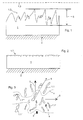
- Fig. 1
- einen schematischen Querschnitt einer Gleitfläche nach dem Aufspritzen;
- Fig. 2
- einen schematischen Querschnitt einer Gleitfläche nach dem Feindrehen;
- Fig. 3
- eine schematische Darstellung des Aufbaus einer Gleitfläche.
- Fig. 1
- a schematic cross section of a sliding surface after spraying;
- Fig. 2
- a schematic cross section of a sliding surface after the fine turning;
- Fig. 3
- a schematic representation of the structure of a sliding surface.
Gemäß Figur 1 ist die Gleitfläche 1 auf eine Trägerfläche 2 aufgespritzt. Die Trägerfläche 2 bildet einen Hohlzylinder mit einer Lagerachse 1.3. Das Maß der Rauhigkeit der Oberfläche 1.2 beträgt maximal 0,5 mm. Die Rauhigkeit ist definiert als Differenz zwischen dem größten und dem kleinsten Abstand der Oberfläche 1.2 zur Lagerachse 1.3. Das Verhältnis der absoluten Schichtdicke der Gleitfläche 1 zum Rauhigkeitsmaß 3 ist in dieser Darstellung nicht maßstabsgetreu.According to Figure 1, the
Figur 2 zeigt die Gleitfläche 1 nach dem Feindrehen der Oberfläche 1.2. Durch das Feindrehen werden die Rauhigkeitsspitzen geglättet. Es verbleibt eine gewisse Restrauhigkeit, welche ein Ölreservoir darstellt. Die Figuren 1 und 2 sind zueinander nicht maßstabsgetreu.FIG. 2 shows the sliding
Durch den Spritzprozess mittels eines in Umfangsrichtung 7 rotierenden Brenners und durch das Aufschmelzen aller Werkstoffpartikel wird auf der Oberfläche 1.2 eine Topographie gemäß Figur 3 erzeugt. Figur 3 zeigt eine als Laufbuchse für einen Kolben eines Verbrennungsmotors ausgebildete Gleitfläche 1. Die Laufrichtung 6 des Kolbens ist mit einem Pfeil gekennzeichnet.By the injection process by means of a burner rotating in the
Die Oberfläche 1.2 besteht überwiegend aus Ausnehmungen 1.1, 1.1', 1.1", 1.1"', die eine Tälerstruktur bilden. Die Ausrichtung 8 ist mittels der Prozessführung des Lichtbogenspritzverfahrens derart erfolgt, dass sich zusätzliche Flussbehinderungen 4, 4' in Kolbenlaufrichtung einstellen. Im Idealfall sind die Ausnehmungen 1.1 in Umfangsrichtung 7 ausgerichtet. Im vorliegenden Beispiel weicht die Ausrichtung 8 ca. um 35° von der Umfangsrichtung 7 ab.The surface 1.2 consists predominantly of recesses 1.1, 1.1 ', 1.1 ", 1.1"', which form a Tälerstruktur. The
Neben den Ausnehmungen 1.1 sind Feststoffschmierinseln 5, 5' in Form von Partikeln in die Gleitfläche 1 eingebracht, die eine Grundtragfähigkeit des tribologischen Systems bilden.In addition to the recesses 1.1
Die vorstehend beschriebene Orientierung der Oberflächenrauhigkeiten wirkt sich vorteilhaft auf die hydrodynamische Druckausbildung aus. Dadurch lässt sich die Tragfähigkeit des tribologischen Systems durch Erhöhung der Schmierfilmdicke auf der Gleitfläche 1 weiter erhöhen. Die Oberflächentopographie ist insgesamt so dargestellt, dass sich ein Peklenit-Faktor kleiner 1 einstellt.The orientation of the surface roughness described above has an advantageous effect on the hydrodynamic pressure formation. As a result, the carrying capacity of the tribological system can be further increased by increasing the lubricant film thickness on the sliding
- 11
- Gleitflächesliding surface
- 1.11.1
- Ausnehmung, TälerstrukturRecess, valley structure
- 1.1'1.1 '
- Ausnehmung, TälerstrukturRecess, valley structure
- 1.1"1.1 "
- Ausnehmung, TälerstrukturRecess, valley structure
- 1.1"'1.1 " '
- Ausnehmung, TälerstrukturRecess, valley structure
- 1.21.2
- Oberflächesurface
- 1.31.3
- Lagerachsebearing axle
- 22
- Trägerflächesupport surface
- 33
- Rauhigkeitsmaßof roughness
- 44
- Flussbehinderungriver disabilities
- 4'4 '
- Flussbehinderungriver disabilities
- 55
- FestschmierstoffinselSolid lubricant Island
- 5'5 '
- FestschmierstoffinselSolid lubricant Island
- 66
- Laufrichtungdirection
- 77
- Umfangsrichtungcircumferentially
- 88th
- Ausrichtungalignment
Claims (10)
- Method for producing a cylindrical sliding surface (1) with a bearing axis (1.3) by arc spraying of material particles of an Fe-based alloy, characterized in that the sliding surface (1) is applied by a rotating spraying tool, and the microstructure of the sliding surface (1) is oriented in the circumferential direction (7) or is oriented so as to deviate by at most 45° from the circumferential direction (7) with respect to the bearing axis (1.3).
- Method as claimed in Claim 1, characterized in that for the spraying operation 95 to 100% of all the material particles are melted, and after the spraying operation recesses (1.1) or valley structures are produced in the sliding surface (1) and/or on the surface (1.2) by precision turning.
- Method as claimed in Claim 1 or 2, characterized in that the sliding surface (1) and the recesses (1.1), after the precision-turning operation, are machined by a microfinishing process, such as, for example ceramfinishing.
- Sliding surface (1) of a bearing, which has been applied by arc spraying to a support surface (2), the sliding surface (1) being formed from an Fe-based alloy, characterized in that the sliding surface (1), in the region of a surface (1.2), has a valley structure formed from recesses (1.1), the recesses (1.1) forming a flow obstacle (4) and having an orientation (8) with respect to a bearing axis (1.3) which deviates by at most 45° from the circumferential direction (7).
- Sliding surface (1) of a bearing as claimed in Claim 4, characterized in that the recesses (1.1) form an oil-holding volume which amounts to between 0.01 and 2 mm3 per cm2 of surface (1.2).
- Sliding surface (1) of a bearing as claimed in Claim 4 or 5, characterized in that the extent of the flow obstacle (4) formed by the surface (1.2) of the sliding surface (1) has a mean Peklenit factor of less than 1.
- Sliding surface (1) of a bearing as claimed in one of Claims 4 to 6, characterized in that the sliding surface (1) is formed from a molybdenum-free Fe-based alloy and/or is formed from an Fe-based alloy which contains between 0.8 and 0.9% of carbon.
- Sliding surface (1) of a bearing as claimed in one of Claims 4 to 7, characterized in that the sliding surface (1) has a roughness of between 0.1 and 0.5 mm following the spraying operation and before the precision-turning operation.
- Sliding surface (1) of a bearing as claimed in one of Claims 4 to 8, characterized in that the sliding surface (1) has a roughness value of between 0.01 and 0.03 mm following the spraying and precision-turning operations.
- Sliding surface (1) of a bearing as claimed in one of Claims 4 to 9, characterized in that the sliding surface (1) is designed as a running sleeve for a piston of an internal combustion engine, and the support surface (2) forms a cylinder wall of a cylinder casing.
Applications Claiming Priority (3)
| Application Number | Priority Date | Filing Date | Title |
|---|---|---|---|
| DE10308422 | 2003-02-27 | ||
| DE10308422A DE10308422B3 (en) | 2003-02-27 | 2003-02-27 | Cylindrical surface of a liner for the cylinder of an internal combustion motor is formed by a rotating arc spraying unit with molten iron alloy particles aligned away from the periphery direction, followed by fine turning/micro-finishing |
| PCT/DE2004/000282 WO2004076708A1 (en) | 2003-02-27 | 2004-02-16 | Method for producing a sliding surface |
Publications (2)
| Publication Number | Publication Date |
|---|---|
| EP1601811A1 EP1601811A1 (en) | 2005-12-07 |
| EP1601811B1 true EP1601811B1 (en) | 2007-12-05 |
Family
ID=32520150
Family Applications (1)
| Application Number | Title | Priority Date | Filing Date |
|---|---|---|---|
| EP04711337A Expired - Lifetime EP1601811B1 (en) | 2003-02-27 | 2004-02-16 | Method for producing a sliding surface |
Country Status (5)
| Country | Link |
|---|---|
| US (1) | US20070092749A1 (en) |
| EP (1) | EP1601811B1 (en) |
| JP (1) | JP2006519304A (en) |
| DE (4) | DE10308422B3 (en) |
| WO (1) | WO2004076708A1 (en) |
Families Citing this family (13)
| Publication number | Priority date | Publication date | Assignee | Title |
|---|---|---|---|---|
| DE102006042549C5 (en) * | 2006-09-11 | 2017-08-17 | Federal-Mogul Burscheid Gmbh | Wet cylinder liner with cavitation-resistant surface |
| JP4935450B2 (en) * | 2007-03-26 | 2012-05-23 | トヨタ自動車株式会社 | Thermal spray coating and formation method thereof, thermal spray material wire and cylinder block |
| DE102007037887B3 (en) * | 2007-08-14 | 2008-11-13 | Ab Skf | coating |
| DE102008053642A1 (en) * | 2008-10-29 | 2010-05-06 | Daimler Ag | Thermally sprayed cylinder liner for a combustion engine, is made of iron based alloy, steel, stainless steel and/or light metal based on aluminum, titanium and/or magnesium |
| DE102009049323B4 (en) | 2009-10-14 | 2011-11-10 | Bayerische Motoren Werke Aktiengesellschaft | Internal combustion engine with a crankcase and method for producing a crankcase |
| JP2011220150A (en) * | 2010-04-06 | 2011-11-04 | Honda Motor Co Ltd | Cylinder bore and method for manufacturing the same |
| DE102010035641A1 (en) | 2010-08-27 | 2012-03-01 | Daimler Ag | Surface finishing of hard layer with defined pore distribution, which is applied on sliding surface by thermal spraying, preferably arc spraying, comprises processing layer by machining, using cutting tool with a cutting edge |
| DE102012002766B4 (en) * | 2012-02-11 | 2014-05-22 | Daimler Ag | Thermally coated component having a friction optimized raceway surface and method of component coating surface simulation of a thermally coated component |
| DE102012015405B4 (en) * | 2012-08-03 | 2014-07-03 | Federal-Mogul Burscheid Gmbh | Cylinder liner and method for its production |
| JP2014044315A (en) * | 2012-08-27 | 2014-03-13 | Fuji Xerox Co Ltd | Developing method, developing device and image forming assembly using the same, and image forming apparatus |
| DE102016110007A1 (en) * | 2016-05-31 | 2017-11-30 | Fraunhofer-Gesellschaft zur Förderung der angewandten Forschung e.V. | Cylinder for a reciprocating engine and method for finishing a cylinder for a reciprocating engine |
| US20190085786A1 (en) * | 2017-09-19 | 2019-03-21 | GM Global Technology Operations LLC | Aluminum cylinder block assemblies and methods of making the same |
| FR3090755B1 (en) * | 2018-12-21 | 2021-01-08 | Poclain Hydraulics Ind | Surface texturing |
Family Cites Families (10)
| Publication number | Priority date | Publication date | Assignee | Title |
|---|---|---|---|---|
| US5363821A (en) * | 1993-07-06 | 1994-11-15 | Ford Motor Company | Thermoset polymer/solid lubricant coating system |
| US5332422A (en) * | 1993-07-06 | 1994-07-26 | Ford Motor Company | Solid lubricant and hardenable steel coating system |
| DE19540572C2 (en) * | 1995-10-31 | 1998-10-15 | Volkswagen Ag | Process for producing a sliding surface on a metal workpiece that ensures hydrodynamic lubrication during operation, and a reciprocating piston machine with cylinder liners produced thereafter |
| EP0858519B1 (en) * | 1995-10-31 | 2000-05-10 | Volkswagen Aktiengesellschaft | Method of producing a sliding surface on a metal workpiece |
| US5820939A (en) * | 1997-03-31 | 1998-10-13 | Ford Global Technologies, Inc. | Method of thermally spraying metallic coatings using flux cored wire |
| DE10054015A1 (en) * | 2000-11-01 | 2002-05-16 | Bosch Gmbh Robert | Sliding surface, especially friction surface, contains depressions that can accommodate and temporarily store wear inducing particles |
| ATE548478T1 (en) * | 2001-05-15 | 2012-03-15 | Sulzer Metco Ag | MASK FOR PLACING ON AN ENGINE BLOCK WHEN THERMALLY COATING CYLINDER BOREES THEREIN AND METHOD USING THE MASK |
| US6863931B2 (en) * | 2001-12-03 | 2005-03-08 | Nissan Motor Co., Ltd. | Manufacturing method of product having sprayed coating film |
| CA2421425A1 (en) * | 2002-04-04 | 2003-10-04 | Sulzer Metco Ag | An apparatus and a method for the thermal coating of a surface |
| JP4496783B2 (en) * | 2004-01-16 | 2010-07-07 | トヨタ自動車株式会社 | Thermal spraying equipment and thermal spraying method |
-
2003
- 2003-02-27 DE DE10308422A patent/DE10308422B3/en not_active Expired - Fee Related
-
2004
- 2004-02-16 DE DE112004000803T patent/DE112004000803D2/en not_active Expired - Fee Related
- 2004-02-16 DE DE502004005650T patent/DE502004005650D1/en not_active Expired - Fee Related
- 2004-02-16 WO PCT/DE2004/000282 patent/WO2004076708A1/en active IP Right Grant
- 2004-02-16 US US10/547,208 patent/US20070092749A1/en not_active Abandoned
- 2004-02-16 JP JP2006501503A patent/JP2006519304A/en not_active Abandoned
- 2004-02-16 EP EP04711337A patent/EP1601811B1/en not_active Expired - Lifetime
- 2004-02-26 DE DE102004009928A patent/DE102004009928A1/en not_active Withdrawn
Also Published As
| Publication number | Publication date |
|---|---|
| EP1601811A1 (en) | 2005-12-07 |
| WO2004076708A1 (en) | 2004-09-10 |
| DE502004005650D1 (en) | 2008-01-17 |
| DE112004000803D2 (en) | 2006-01-19 |
| US20070092749A1 (en) | 2007-04-26 |
| DE102004009928A1 (en) | 2004-09-23 |
| DE10308422B3 (en) | 2004-07-15 |
| JP2006519304A (en) | 2006-08-24 |
Similar Documents
| Publication | Publication Date | Title |
|---|---|---|
| EP1601811B1 (en) | Method for producing a sliding surface | |
| DE102005057754B4 (en) | Piston for internal combustion engine | |
| DE10308563B3 (en) | Cylinder lining for engines comprises substrate with wear-resistant coating produced by wire-arc spraying which contains martensitic phases and oxygen | |
| WO2007031160A1 (en) | Bearing arrangement | |
| EP2324260A1 (en) | Sliding element having a multiple layer | |
| EP0858519B1 (en) | Method of producing a sliding surface on a metal workpiece | |
| EP0491978B1 (en) | Cylinder block for internal combustion engine | |
| EP1711642B1 (en) | Ferrous layer for a sliding surface, in particular for cylinder running surfaces on engine blocks, applied by means of thermal spraying | |
| DE4423543C2 (en) | Low friction camshaft | |
| DE102006008910B4 (en) | Piston pin with sliding layers for connecting rod eyes in internal combustion engines | |
| DE102007054181A1 (en) | Corrosion-resistant coating and manufacturing method thereof | |
| EP1789687B1 (en) | Bearing device | |
| DE102018202540B4 (en) | Engine block of a combustion engine with optimized thermal conductivity properties | |
| DE10223836C1 (en) | Solid body sliding pair used for machine components exposed to high pressure and high temperature comprises sliding elements containing slip additive in the form of hydroxide compound which is incorporated in the base material before use | |
| DE202005002954U1 (en) | Piston pump for regulated automobile braking system has brake fluid layer acting as lubricant between each piston and enclosing guide sleeve | |
| EP3601629B1 (en) | Piston ring with shot-peened running-in layer and method for the production thereof | |
| DE10308562B3 (en) | Cylinder liner in engine blocks of I.C. engines comprises a wear protection coating based on an iron alloy with carbon and oxygen or based on titanium arranged on a partial region of the base body of the liner | |
| DE102017119437A1 (en) | STEEL ALLOYS AND CYLINDER SLEEVES FROM SELF | |
| DE102019219378A1 (en) | Cylinder liner for an internal combustion engine | |
| EP1127958A2 (en) | Process for coating a surface | |
| EP1450080A1 (en) | Piston for an internal combustion engine, combination of a piston with a gudgeon pin and/or a connecting rod and a method of their manufacturing | |
| WO2018158419A1 (en) | Gudgeon pin for internal combustion engines, system, engine and use of a gudgeon pin of this type | |
| EP1753887B1 (en) | Heavy-duty engine component | |
| EP0033969B1 (en) | Piston engine block with bimetallic cylinder | |
| DE3614185A1 (en) | METHOD FOR THE PRODUCTION OF HIGH-QUALITY LIFTING VALVES FOR INTERNAL COMBUSTION ENGINES |
Legal Events
| Date | Code | Title | Description |
|---|---|---|---|
| PUAI | Public reference made under article 153(3) epc to a published international application that has entered the european phase |
Free format text: ORIGINAL CODE: 0009012 |
|
| 17P | Request for examination filed |
Effective date: 20050726 |
|
| AK | Designated contracting states |
Kind code of ref document: A1 Designated state(s): AT BE BG CH CY CZ DE DK EE ES FI FR GB GR HU IE IT LI LU MC NL PT RO SE SI SK TR |
|
| AX | Request for extension of the european patent |
Extension state: AL LT LV MK |
|
| DAX | Request for extension of the european patent (deleted) | ||
| RBV | Designated contracting states (corrected) |
Designated state(s): DE ES FR GB IT |
|
| RIN1 | Information on inventor provided before grant (corrected) |
Inventor name: SAGEL, ALEXANDER Inventor name: WANKE, CHRISTIAN Inventor name: SCHMID, JOERN Inventor name: IZQUIERDO, PATRICK Inventor name: HEUBERGER, AXEL |
|
| RIN1 | Information on inventor provided before grant (corrected) |
Inventor name: WANKE, CHRISTIAN Inventor name: SAGEL, ALEXANDER Inventor name: HEUBERGER, AXEL Inventor name: IZQUIERDO, PATRICK Inventor name: SCHMID, JOERN |
|
| RIN1 | Information on inventor provided before grant (corrected) |
Inventor name: IZQUIERDO, PATRICK Inventor name: HEUBERGER, AXEL Inventor name: SCHMID, JOERN Inventor name: SAGEL, ALEXANDER Inventor name: WANKE, CHRISTIAN |
|
| RIN1 | Information on inventor provided before grant (corrected) |
Inventor name: IZQUIERDO, PATRICK Inventor name: HEUBERGER, AXEL Inventor name: SCHMID, JOERN Inventor name: SAGEL, ALEXANDER, DR. Inventor name: WANKE, CHRISTIAN |
|
| RAP1 | Party data changed (applicant data changed or rights of an application transferred) |
Owner name: DAIMLERCHRYSLER AG |
|
| GRAP | Despatch of communication of intention to grant a patent |
Free format text: ORIGINAL CODE: EPIDOSNIGR1 |
|
| GRAS | Grant fee paid |
Free format text: ORIGINAL CODE: EPIDOSNIGR3 |
|
| GRAA | (expected) grant |
Free format text: ORIGINAL CODE: 0009210 |
|
| AK | Designated contracting states |
Kind code of ref document: B1 Designated state(s): DE ES FR GB IT |
|
| REG | Reference to a national code |
Ref country code: GB Ref legal event code: FG4D Free format text: NOT ENGLISH |
|
| RAP2 | Party data changed (patent owner data changed or rights of a patent transferred) |
Owner name: DAIMLER AG |
|
| REF | Corresponds to: |
Ref document number: 502004005650 Country of ref document: DE Date of ref document: 20080117 Kind code of ref document: P |
|
| PG25 | Lapsed in a contracting state [announced via postgrant information from national office to epo] |
Ref country code: ES Free format text: LAPSE BECAUSE OF FAILURE TO SUBMIT A TRANSLATION OF THE DESCRIPTION OR TO PAY THE FEE WITHIN THE PRESCRIBED TIME-LIMIT Effective date: 20080316 |
|
| GBV | Gb: ep patent (uk) treated as always having been void in accordance with gb section 77(7)/1977 [no translation filed] | ||
| EN | Fr: translation not filed | ||
| PLBE | No opposition filed within time limit |
Free format text: ORIGINAL CODE: 0009261 |
|
| STAA | Information on the status of an ep patent application or granted ep patent |
Free format text: STATUS: NO OPPOSITION FILED WITHIN TIME LIMIT |
|
| 26N | No opposition filed |
Effective date: 20080908 |
|
| PG25 | Lapsed in a contracting state [announced via postgrant information from national office to epo] |
Ref country code: GB Free format text: LAPSE BECAUSE OF FAILURE TO SUBMIT A TRANSLATION OF THE DESCRIPTION OR TO PAY THE FEE WITHIN THE PRESCRIBED TIME-LIMIT Effective date: 20071205 |
|
| PG25 | Lapsed in a contracting state [announced via postgrant information from national office to epo] |
Ref country code: FR Free format text: LAPSE BECAUSE OF FAILURE TO SUBMIT A TRANSLATION OF THE DESCRIPTION OR TO PAY THE FEE WITHIN THE PRESCRIBED TIME-LIMIT Effective date: 20081003 |
|
| PGFP | Annual fee paid to national office [announced via postgrant information from national office to epo] |
Ref country code: DE Payment date: 20090219 Year of fee payment: 6 |
|
| PG25 | Lapsed in a contracting state [announced via postgrant information from national office to epo] |
Ref country code: DE Free format text: LAPSE BECAUSE OF NON-PAYMENT OF DUE FEES Effective date: 20100901 Ref country code: IT Free format text: LAPSE BECAUSE OF NON-PAYMENT OF DUE FEES Effective date: 20080229 |