EP1601227B1 - Loudspeaker - Google Patents
Loudspeaker Download PDFInfo
- Publication number
- EP1601227B1 EP1601227B1 EP05253173.8A EP05253173A EP1601227B1 EP 1601227 B1 EP1601227 B1 EP 1601227B1 EP 05253173 A EP05253173 A EP 05253173A EP 1601227 B1 EP1601227 B1 EP 1601227B1
- Authority
- EP
- European Patent Office
- Prior art keywords
- dome
- loudspeaker according
- ring
- loudspeaker
- diameter
- Prior art date
- Legal status (The legal status is an assumption and is not a legal conclusion. Google has not performed a legal analysis and makes no representation as to the accuracy of the status listed.)
- Expired - Lifetime
Links
Images


Classifications
-
- H—ELECTRICITY
- H04—ELECTRIC COMMUNICATION TECHNIQUE
- H04R—LOUDSPEAKERS, MICROPHONES, GRAMOPHONE PICK-UPS OR LIKE ACOUSTIC ELECTROMECHANICAL TRANSDUCERS; ELECTRIC HEARING AIDS; PUBLIC ADDRESS SYSTEMS
- H04R9/00—Transducers of moving-coil, moving-strip, or moving-wire type
- H04R9/02—Details
- H04R9/025—Magnetic circuit
-
- H—ELECTRICITY
- H04—ELECTRIC COMMUNICATION TECHNIQUE
- H04R—LOUDSPEAKERS, MICROPHONES, GRAMOPHONE PICK-UPS OR LIKE ACOUSTIC ELECTROMECHANICAL TRANSDUCERS; ELECTRIC HEARING AIDS; PUBLIC ADDRESS SYSTEMS
- H04R7/00—Diaphragms for electromechanical transducers; Cones
- H04R7/02—Diaphragms for electromechanical transducers; Cones characterised by the construction
- H04R7/12—Non-planar diaphragms or cones
- H04R7/127—Non-planar diaphragms or cones dome-shaped
-
- H—ELECTRICITY
- H04—ELECTRIC COMMUNICATION TECHNIQUE
- H04R—LOUDSPEAKERS, MICROPHONES, GRAMOPHONE PICK-UPS OR LIKE ACOUSTIC ELECTROMECHANICAL TRANSDUCERS; ELECTRIC HEARING AIDS; PUBLIC ADDRESS SYSTEMS
- H04R9/00—Transducers of moving-coil, moving-strip, or moving-wire type
- H04R9/02—Details
- H04R9/04—Construction, mounting, or centering of coil
- H04R9/045—Mounting
-
- H—ELECTRICITY
- H04—ELECTRIC COMMUNICATION TECHNIQUE
- H04R—LOUDSPEAKERS, MICROPHONES, GRAMOPHONE PICK-UPS OR LIKE ACOUSTIC ELECTROMECHANICAL TRANSDUCERS; ELECTRIC HEARING AIDS; PUBLIC ADDRESS SYSTEMS
- H04R2307/00—Details of diaphragms or cones for electromechanical transducers, their suspension or their manufacture covered by H04R7/00 or H04R31/003, not provided for in any of its subgroups
- H04R2307/027—Diaphragms comprising metallic materials
-
- H—ELECTRICITY
- H04—ELECTRIC COMMUNICATION TECHNIQUE
- H04R—LOUDSPEAKERS, MICROPHONES, GRAMOPHONE PICK-UPS OR LIKE ACOUSTIC ELECTROMECHANICAL TRANSDUCERS; ELECTRIC HEARING AIDS; PUBLIC ADDRESS SYSTEMS
- H04R7/00—Diaphragms for electromechanical transducers; Cones
- H04R7/16—Mounting or tensioning of diaphragms or cones
- H04R7/18—Mounting or tensioning of diaphragms or cones at the periphery
Definitions
- the present invention relates to improvements in loudspeakers.
- the application proposes an improved dome construction, particularly, but not exclusively, for high frequency loudspeakers.
- a dome is mounted at its periphery to a support through a flexible surround which allows the dome to move axially.
- the edge of the dome is also coupled to a voice coil mounted in the gap between the poles of a permanent magnet, movement of the dome being caused by changes in the polarity of the electrical supply to the voice coil.
- the dome is metallic, e.g. aluminium, and the voice coil is wound on a polymeric former suitably attached to the dome.
- the dome At low frequencies, the dome, subjected to a cyclic force from the voice coil, behaves as a rigid body with all points on its surface moving with the same axial velocity. At some higher frequency, known as the first break-up mode, however, the structure will exhibit a resonant mode where the central part of the dome moves axially while the edge of the dome moves radially. This point marks the high frequency limit of the driver and the aim of the loudspeaker designer is to maximise this value.
- dome profile used by most manufacturers has traditionally been spherical. However, the Applicant has recognised that this is not optimum from the point of view of first mode break up, and in fact the ideal shape is that of a catenary or parabola.
- a loudspeaker dome having the features of the preamble of claim 1 is disclosed in US-A-4531608 or in WO 03/101148 A .
- the invention provides a loudspeaker dome as set forth in claim 1.
- the profile of the dome matches that of a catenary or parabola to within 1.5%, more preferably 1%, more preferably 0.5% over its diameter.
- the profile of the dome should lie not more than +/- 1.5%, more preferably +/- 1%, more preferably +/-0.5%, of the dome height away from the catenary or parabola which passes through two points which define the diameter of the dome and the central point which defines the dome height.
- the dome is stiffened by a stiffening ring suitably attached to the dome.
- the ring is of a high modulus carbon fibre, as that provides excellent stiffness, but low weight.
- the ring has a stiffness of 5000/ (dome diameter in metres) Nm -1 . Preferably also it has a cross sectional area of more than about 0.002% of the dome area.
- the Young's Modulus of the ring is over 300 GNm -2 , typically 800 GNm -2 .
- the ring is attached to the dome at a position no more than 10%, more preferably no more than 5% of the dome diameter inwardly from the dome edge.
- the ring is bonded to the dome. More preferably, the ring is formed in situ onto the dome.
- a suitable stiffening material such as carbon fibre, may be laid into an adhesive deposited onto the dome.
- the adhesive when cured, is at least slightly resilient so as to give better damping.
- the stiffening may be applied either to the internal or external face of the dome.
- the ring is formed in an internal corner of the dome.
- the dome can be made from any suitable material, but preferably it is metallic. Most preferably the dome is made from aluminium, titanium or magnesium.
- the dome is anodised, most preferably to a depth of over 5% of the dome thickness.
- the dome will have a thickness of less than 0.1% of its diameter. Typically therefore, the dome will be between 25 and 75 microns thick.
- a magnet design for a loudspeaker which is also particularly, but not exclusively, suited to high frequency loudspeakers.
- a loudspeaker operates through the movement of a voice coil in a magnetic gap.
- the transduction efficiency of the loudspeaker is related to the flux in the magnetic gap and, particularly for high frequency drivers, a high value is desirable.
- the present application therefore describes a magnet construction for a loudspeaker, comprising: a magnet; an inner pole; an outer pole spaced radially from said inner pole so as to define a space therebetween; said space having a first part defining a relatively narrow magnetic gap for receiving a voice coil of the loudspeaker, and a second, wider part receiving said magnet; said first part and second part being joined by a tapering part which also receives a magnetic material.
- the additional magnetic material may be separate from or formed as part of the main magnet of the construction.
- the additional magnetic material may extend as close to the magnetic gap as is allowed by the movement of the coil in the gap.
- This aspect of the disclosure is particularly applicable to systems using magnetic materials having a high coercivity and high energy product such as neodymium iron boron.
- a high frequency loudspeaker driver 2 comprises a magnet 4, a steel shell 6 and a steel pole 8.
- a magnetic gap 10 is formed between the steel shell 6 and steel pole 8, and this gap receives a voice coil 12 which is formed on a coil former 14 attached to a dome 16.
- the dome 16 is mounted to the steel shell 6 by a resilient support member 18 which is bonded to the dome and suitably supported on the shell 6. As described so far, this is a conventional construction.
- the dome 16 is not of a conventional construction.
- the dome 16 is shaped as a catenary, as opposed to the standard spherical shape. (i.e. a vertical section through the dome has a catenary shape).
- the dome profile can lie within a +/-1% band of the ideal curve, i.e. lie between a pair of limit curves created by offsetting the ideal catenary curve passing through the edge of the dome and its centre by +/- 1% of the central dome height.
- the periphery of the dome 16 is stiffened by a ring 20 of carbon fibre positioned internally of the dome 16 at the base of the dome 16.
- the carbon fibre ring 20 is formed in situ on the dome 16.
- two turns of 1000 tex carbon fibre toe 22 having a Young's Modulus of 800 GNm -2 are wound into a PVA adhesive matrix 24 at the base of the dome 16 and the adhesive allowed to cure.
- the resultant ring 20 has a cross sectional area of over 0.05mm 2 and a stiffness of 100,000 Nm -1 .
- the PVA adhesive is preferred as it is provides better damping than a more rigid matrix.
- the dome itself is 50mm in diameter and is formed from anodised aluminium, with a thickness of 50 microns.
- the stiffening ring 20 may be placed externally of the dome, for example in the region 26 between the dome 16 and the resilient support 18.
- other materials may be used to from the stiffening ring. Carbon fibre is preferred however due to its high stiffness and low weight.
- the area of stiffening material laid down will depend on the modulus of that material. A lower modulus material will require a greater area to give the desired stiffness to the dome periphery.
- the dome may have a parabolic, rather than a catenary profile.
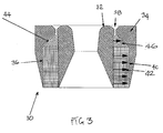
- FIG. 3 this illustrates a magnet construction 30.
- the construction comprises an inner steel pole 32 and an outer steel pole 34 spaced radially outwardly from the inner pole 32.
- the poles 32, 34 are typically of low lead steel.
- a space 36 is defined between the two poles 32, 34.
- the space 36 has a first portion 38 at one end which forms a magnetic gap to receive a voice coil (not shown).
- the space 36 also has a rectangular second portion 40 which receives a radially polarised magnet 42, for example of a 35MOe 150°C sintered material.
- the space 36 also has a third portion 44 which tapers from the second portion 40 to the first portion 38.
- the tapering space portion 44 receives additional magnetic material 46. This brings the magnetic material much closer to the magnetic gap 38, reducing flux losses in that region.
Landscapes
- Engineering & Computer Science (AREA)
- Physics & Mathematics (AREA)
- Acoustics & Sound (AREA)
- Signal Processing (AREA)
- Multimedia (AREA)
- Audible-Bandwidth Dynamoelectric Transducers Other Than Pickups (AREA)
- Diaphragms For Electromechanical Transducers (AREA)
Description
- The present invention relates to improvements in loudspeakers.
- In a first aspect the application proposes an improved dome construction, particularly, but not exclusively, for high frequency loudspeakers.
- In a known design, a dome is mounted at its periphery to a support through a flexible surround which allows the dome to move axially. The edge of the dome is also coupled to a voice coil mounted in the gap between the poles of a permanent magnet, movement of the dome being caused by changes in the polarity of the electrical supply to the voice coil. Typically the dome is metallic, e.g. aluminium, and the voice coil is wound on a polymeric former suitably attached to the dome.
- At low frequencies, the dome, subjected to a cyclic force from the voice coil, behaves as a rigid body with all points on its surface moving with the same axial velocity. At some higher frequency, known as the first break-up mode, however, the structure will exhibit a resonant mode where the central part of the dome moves axially while the edge of the dome moves radially. This point marks the high frequency limit of the driver and the aim of the loudspeaker designer is to maximise this value.
- The dome profile used by most manufacturers has traditionally been spherical. However, the Applicant has recognised that this is not optimum from the point of view of first mode break up, and in fact the ideal shape is that of a catenary or parabola.
- A loudspeaker dome having the features of the preamble of claim 1 is disclosed in
US-A-4531608 or inWO 03/101148 A - The invention provides a loudspeaker dome as set forth in claim 1.
- Preferably the profile of the dome matches that of a catenary or parabola to within 1.5%, more preferably 1%, more preferably 0.5% over its diameter. By this is meant that the profile of the dome should lie not more than +/- 1.5%, more preferably +/- 1%, more preferably +/-0.5%, of the dome height away from the catenary or parabola which passes through two points which define the diameter of the dome and the central point which defines the dome height.
- It has also been found that in order to optimise the performance of such a dome, the edge region of the dome should be stiffened
- Therefore, the dome is stiffened by a stiffening ring suitably attached to the dome. Preferably the ring is of a high modulus carbon fibre, as that provides excellent stiffness, but low weight.
- Preferably the ring has a stiffness of 5000/ (dome diameter in metres) Nm-1. Preferably also it has a cross sectional area of more than about 0.002% of the dome area. The Young's Modulus of the ring is over 300 GNm-2, typically 800 GNm-2.
- Preferably the ring is attached to the dome at a position no more than 10%, more preferably no more than 5% of the dome diameter inwardly from the dome edge. Preferably the ring is bonded to the dome. More preferably, the ring is formed in situ onto the dome. In a preferred embodiment, a suitable stiffening material, such as carbon fibre, may be laid into an adhesive deposited onto the dome. Preferably the adhesive, when cured, is at least slightly resilient so as to give better damping.
- The stiffening may be applied either to the internal or external face of the dome. In a particularly preferred embodiment, the ring is formed in an internal corner of the dome.
- The dome can be made from any suitable material, but preferably it is metallic. Most preferably the dome is made from aluminium, titanium or magnesium.
- Preferably the dome is anodised, most preferably to a depth of over 5% of the dome thickness.
- Preferably the dome will have a thickness of less than 0.1% of its diameter. Typically therefore, the dome will be between 25 and 75 microns thick.
- Also disclosed is a magnet design for a loudspeaker which is also particularly, but not exclusively, suited to high frequency loudspeakers.
- As discussed above, a loudspeaker operates through the movement of a voice coil in a magnetic gap. The transduction efficiency of the loudspeaker is related to the flux in the magnetic gap and, particularly for high frequency drivers, a high value is desirable.
- Most magnet systems employ a permanent magnet together with soft iron pole to channel and concentrate the flux in the magnetic gap in which the voice coil is located. Major problems arising in the design of high flux systems are the saturation of the iron and the leakage of flux from all the iron surfaces not in the gap. The issue of leakage is most acute where the steelwork is closest together just outside the gap.
- Simply increasing the size of the magnet can only deal with problem up to a point, as the area of associated steel pole material increases, with attendant losses.
- In a high frequency driver magnet system there is often found a space adjacent to the gap which tapers from the magnet width to the gap width and this region is one of the worst for flux leakage. The applicant has recognised that the gap flux can be significantly improved if that space is filled, at least in part, by magnetic material.
- The present application therefore describes a magnet construction for a loudspeaker, comprising: a magnet; an inner pole; an outer pole spaced radially from said inner pole so as to define a space therebetween; said space having a first part defining a relatively narrow magnetic gap for receiving a voice coil of the loudspeaker, and a second, wider part receiving said magnet; said first part and second part being joined by a tapering part which also receives a magnetic material.
- The additional magnetic material may be separate from or formed as part of the main magnet of the construction.
- The additional magnetic material may extend as close to the magnetic gap as is allowed by the movement of the coil in the gap.
- This aspect of the disclosure is particularly applicable to systems using magnetic materials having a high coercivity and high energy product such as neodymium iron boron.
- Some preferred embodiments of the invention will now be described by way of example only with reference to the accompanying drawings in which:
-
Figure 1 shows a first embodiment of the invention; -
Figure 2 shows a detail of the construction ofFigure 1 ; and -
Figure 3 shows a magnet construction of the application. - With reference to
Figures 1 and2 , a high frequency loudspeaker driver 2 comprises amagnet 4, a steel shell 6 and a steel pole 8. Amagnetic gap 10 is formed between the steel shell 6 and steel pole 8, and this gap receives avoice coil 12 which is formed on a coil former 14 attached to adome 16. Thedome 16 is mounted to the steel shell 6 by aresilient support member 18 which is bonded to the dome and suitably supported on the shell 6. As described so far, this is a conventional construction. - The
dome 16, however, is not of a conventional construction. In the embodiment shown, thedome 16 is shaped as a catenary, as opposed to the standard spherical shape. (i.e. a vertical section through the dome has a catenary shape). The dome profile can lie within a +/-1% band of the ideal curve, i.e. lie between a pair of limit curves created by offsetting the ideal catenary curve passing through the edge of the dome and its centre by +/- 1% of the central dome height. In addition, the periphery of thedome 16 is stiffened by aring 20 of carbon fibre positioned internally of thedome 16 at the base of thedome 16. - The
carbon fibre ring 20 is formed in situ on thedome 16. In this particular embodiment, for a 50 mm diameter dome, two turns of 1000 texcarbon fibre toe 22 having a Young's Modulus of 800 GNm-2 are wound into a PVAadhesive matrix 24 at the base of thedome 16 and the adhesive allowed to cure. Theresultant ring 20 has a cross sectional area of over 0.05mm2 and a stiffness of 100,000 Nm-1. The PVA adhesive is preferred as it is provides better damping than a more rigid matrix. - The dome itself is 50mm in diameter and is formed from anodised aluminium, with a thickness of 50 microns.
- While a prior art 50mm dome might have a first mode at 13kHz, it has been found that the first mode of a dome as described above can exceed 21kHz, a very significant increase.
- It will be appreciated that various modifications can be made to the above embodiment without departing from the scope of the invention. For example, the stiffening
ring 20 may be placed externally of the dome, for example in theregion 26 between thedome 16 and theresilient support 18. Also, other materials may be used to from the stiffening ring. Carbon fibre is preferred however due to its high stiffness and low weight. Also, the area of stiffening material laid down will depend on the modulus of that material. A lower modulus material will require a greater area to give the desired stiffness to the dome periphery. Also, the dome may have a parabolic, rather than a catenary profile. - Turning now to
Figure 3 , this illustrates amagnet construction 30. The construction comprises aninner steel pole 32 and anouter steel pole 34 spaced radially outwardly from theinner pole 32. Thepoles space 36 is defined between the twopoles - The
space 36 has afirst portion 38 at one end which forms a magnetic gap to receive a voice coil (not shown). Thespace 36 also has a rectangularsecond portion 40 which receives a radially polarisedmagnet 42, for example of a 35MOe 150°C sintered material. Thespace 36 also has athird portion 44 which tapers from thesecond portion 40 to thefirst portion 38. - As described so far this construction is conventional. However, in accordance with the present disclosure the tapering
space portion 44 receives additionalmagnetic material 46. This brings the magnetic material much closer to themagnetic gap 38, reducing flux losses in that region. - It has been found that in a prior art construction with a 26mm pole diameter and gap dimensions of 0.7mm x 1.8mm developing 2.2T, the present arrangement will allow an increase of 0.2T.
Claims (15)
- A loudspeaker having a dome (16) wherein the edge region of the dome is stiffened by a ring suitably attached to the dome (16);
characterised in that said dome has a substantially parabolic or catenary shape; and
in that the Young's Modulus of the ring is over 300GNm-2. - A loudspeaker according to claim 1 wherein the profile of the dome (16) matches that of a catenary or parabola to within 1.5%, more preferably 1%, more preferably 0.5 %, over its diameter.
- A loudspeaker according to claim 1 or 2 wherein the ring (20) is of a high modulus material, preferably carbon fibre.
- A loudspeaker according to any preceding claim wherein the ring (20) has a stiffness of at least 5000/ (dome diameter in metres) Nm-1.
- A loudspeaker according to claim 1, 2 or 3 wherein cross sectional area of the ring (20) is more than about 0.002% of the dome area.
- A loudspeaker according to any preceding claim wherein the ring (20) is attached to the dome (16) at a position no more than 10%, more preferably no more than 5% of the dome diameter inwardly from the dome edge.
- A loudspeaker according to any preceding claim wherein the ring (20) is bonded to the dome (16) by adhesive.
- A loudspeaker according to any preceding claim wherein the ring (20) is formed in situ on the dome (16).
- A loudspeaker according to claim 8 wherein a stiffening material, such as carbon fibre, is laid into an adhesive deposited onto the dome (16).
- A loudspeaker according to any of claims 7 to 9 wherein the adhesive, when cured, is at least slightly resilient.
- A loudspeaker according to any preceding claim wherein the stiffening is applied to the internal face of the dome (16).
- A loudspeaker according to any preceding claim wherein the dome (16) is metallic.
- A loudspeaker according to claim 12 wherein the dome (16) is made from aluminium, titanium or magnesium.
- A loudspeaker according to claim 12 or 13 wherein the dome (16) is anodised.
- A loudspeaker according to any preceding claim wherein the dome (16) has a thickness of less than 0.1% of its diameter.
Applications Claiming Priority (2)
| Application Number | Priority Date | Filing Date | Title |
|---|---|---|---|
| GB0411564 | 2004-05-24 | ||
| GB0411564A GB2414619A (en) | 2004-05-24 | 2004-05-24 | Loudspeaker with parabolic or catenary shaped dome |
Publications (3)
| Publication Number | Publication Date |
|---|---|
| EP1601227A2 EP1601227A2 (en) | 2005-11-30 |
| EP1601227A3 EP1601227A3 (en) | 2008-12-31 |
| EP1601227B1 true EP1601227B1 (en) | 2016-03-09 |
Family
ID=32607872
Family Applications (1)
| Application Number | Title | Priority Date | Filing Date |
|---|---|---|---|
| EP05253173.8A Expired - Lifetime EP1601227B1 (en) | 2004-05-24 | 2005-05-24 | Loudspeaker |
Country Status (3)
| Country | Link |
|---|---|
| US (1) | US8630440B2 (en) |
| EP (1) | EP1601227B1 (en) |
| GB (1) | GB2414619A (en) |
Families Citing this family (8)
| Publication number | Priority date | Publication date | Assignee | Title |
|---|---|---|---|---|
| WO2010037822A1 (en) * | 2008-10-01 | 2010-04-08 | Ortofon A/S | Magnetic assembly suitable for audio cartridges |
| GB2505953B (en) | 2012-09-18 | 2019-05-08 | B & W Group Ltd | Stepped thickness change in dome-shaped diaphragms for loudspeaker drive units or microphones |
| DE102014211687A1 (en) * | 2014-06-18 | 2015-12-24 | Sennheiser Electronic Gmbh & Co. Kg | Electrodynamic transducer |
| US10291990B2 (en) | 2016-10-26 | 2019-05-14 | Apple Inc. | Unibody diaphragm and former for a speaker |
| US10555085B2 (en) | 2017-06-16 | 2020-02-04 | Apple Inc. | High aspect ratio moving coil transducer |
| CN109561368B (en) * | 2017-09-26 | 2023-08-11 | 惠州迪芬尼声学科技股份有限公司 | Hard ball top high pitch loudspeaker |
| CN109788404A (en) * | 2018-12-29 | 2019-05-21 | 瑞声科技(南京)有限公司 | Vibrating diaphragm and microphone device |
| US12069459B2 (en) * | 2020-10-19 | 2024-08-20 | Harman International Industries, Incorporated | Loudspeaker assembly with a separate voice coil assembly |
Citations (1)
| Publication number | Priority date | Publication date | Assignee | Title |
|---|---|---|---|---|
| WO2003101148A1 (en) * | 2002-05-28 | 2003-12-04 | Sony Corporation | Speaker with diaphragm reinforcing ring |
Family Cites Families (14)
| Publication number | Priority date | Publication date | Assignee | Title |
|---|---|---|---|---|
| FR666804A (en) * | 1928-04-28 | 1929-10-07 | Improvements to sound reproduction devices, such as telephone loudspeakers | |
| GB334350A (en) | 1929-08-02 | 1930-09-04 | Frederick Maurice Laserson | Improvements in or relating to mounting cone diaphragms of loud speakers and the like |
| DE1281600B (en) | 1958-06-25 | 1968-10-31 | Magnetfab Bonn Gmbh | Annular gap magnet system with high field strength in which a coil moves in the air gap |
| DE3138566A1 (en) * | 1981-09-28 | 1983-04-07 | Siegfried Dr. 75009 Paris Klein | LOUDSPEAKERS, ESPECIALLY HIGH-TONE SPEAKERS |
| NL8204839A (en) * | 1982-01-04 | 1983-08-01 | Jensen Int Inc | ELECTRO-DYNAMIC ACTUATOR FOR A SPEAKER AND ACCOMPANYING MEMBRANE. |
| US4531608A (en) | 1982-10-29 | 1985-07-30 | Heinz Harro K | High frequency compression driver |
| GB2155733B (en) | 1983-12-03 | 1987-10-21 | Pioneer Electronic Corp | Voice coil speaker |
| DE3917477A1 (en) * | 1989-05-30 | 1990-12-06 | Eton Deutschland Electro Acous | Parabolic loudspeaker membrane - is made of aluminium foil and has oscillator coil on outside of membrane |
| JPH10175498A (en) * | 1996-12-20 | 1998-06-30 | Kansei Corp | Side air bag |
| JP3569413B2 (en) * | 1997-03-25 | 2004-09-22 | パイオニア株式会社 | Speaker device and method of manufacturing speaker device |
| JP4122602B2 (en) * | 1998-11-19 | 2008-07-23 | ソニー株式会社 | Speaker device |
| JP2001346291A (en) * | 2000-06-05 | 2001-12-14 | Sony Corp | Speaker device |
| CA2407123C (en) * | 2001-10-16 | 2007-12-18 | Audio Products International Corp. | Low distortion loudspeaker cone suspension |
| US7177439B2 (en) | 2003-03-06 | 2007-02-13 | Peavey Electronics Corporation | Methods and apparatus for dissipating heat in a voice coil |
-
2004
- 2004-05-24 GB GB0411564A patent/GB2414619A/en not_active Withdrawn
-
2005
- 2005-05-23 US US11/136,014 patent/US8630440B2/en not_active Expired - Fee Related
- 2005-05-24 EP EP05253173.8A patent/EP1601227B1/en not_active Expired - Lifetime
Patent Citations (2)
| Publication number | Priority date | Publication date | Assignee | Title |
|---|---|---|---|---|
| WO2003101148A1 (en) * | 2002-05-28 | 2003-12-04 | Sony Corporation | Speaker with diaphragm reinforcing ring |
| US20060088184A1 (en) * | 2002-05-28 | 2006-04-27 | Yoshio Ohashi | Speaker device |
Also Published As
| Publication number | Publication date |
|---|---|
| GB2414619A (en) | 2005-11-30 |
| GB0411564D0 (en) | 2004-06-23 |
| US8630440B2 (en) | 2014-01-14 |
| EP1601227A3 (en) | 2008-12-31 |
| US20060000666A1 (en) | 2006-01-05 |
| EP1601227A2 (en) | 2005-11-30 |
Similar Documents
| Publication | Publication Date | Title |
|---|---|---|
| KR101690830B1 (en) | System for vibration confinement | |
| US7292707B2 (en) | Loudspeaker | |
| EP2564602B1 (en) | Loudspeaker and diaphragm therefor | |
| EP3550854B1 (en) | Loudspeaker with dual plate structure | |
| US10506348B2 (en) | Speaker | |
| EP1601227A2 (en) | Loudspeaker | |
| US20060251286A1 (en) | Multi-gap air return motor for electromagnetic transducer | |
| JP2007096436A (en) | Speaker | |
| CN209283485U (en) | Loudspeaker | |
| EP1833278B1 (en) | Speaker | |
| EP1788842A2 (en) | Speaker apparatus | |
| US6735323B1 (en) | Speaker | |
| US8098878B2 (en) | Miniature voice coil with integrated coupling coil | |
| US20110103638A1 (en) | Voice coil support for a coil transducer motor structure | |
| CN101385388A (en) | Damper for speaker and speaker using the damper | |
| US20100177925A1 (en) | Speaker Device | |
| US7149322B2 (en) | Magnetic circuit for loudspeaker and loudspeaker comprising it | |
| JP4560372B2 (en) | Speaker device | |
| JP4264579B2 (en) | Speaker device | |
| US6302626B1 (en) | Fixed support for voice coil motor | |
| US11968509B2 (en) | Speaker | |
| CN110958543A (en) | Vibrating diaphragm and sound generating device | |
| GB2593749A (en) | Improvements in and relating to loudspeaker magnet assemblies | |
| JP4507827B2 (en) | Corrugation damper and speaker device | |
| JP2008028459A (en) | Conduction speaker |
Legal Events
| Date | Code | Title | Description |
|---|---|---|---|
| PUAI | Public reference made under article 153(3) epc to a published international application that has entered the european phase |
Free format text: ORIGINAL CODE: 0009012 |
|
| AK | Designated contracting states |
Kind code of ref document: A2 Designated state(s): AT BE BG CH CY CZ DE DK EE ES FI FR GB GR HU IE IS IT LI LT LU MC NL PL PT RO SE SI SK TR |
|
| AX | Request for extension of the european patent |
Extension state: AL BA HR LV MK YU |
|
| PUAL | Search report despatched |
Free format text: ORIGINAL CODE: 0009013 |
|
| AK | Designated contracting states |
Kind code of ref document: A3 Designated state(s): AT BE BG CH CY CZ DE DK EE ES FI FR GB GR HU IE IS IT LI LT LU MC NL PL PT RO SE SI SK TR |
|
| AX | Request for extension of the european patent |
Extension state: AL BA HR LV MK YU |
|
| 17P | Request for examination filed |
Effective date: 20090630 |
|
| AKX | Designation fees paid |
Designated state(s): AT BE BG CH CY CZ DE DK EE ES FI FR GB GR HU IE IS IT LI LT LU MC NL PL PT RO SE SI SK TR |
|
| 17Q | First examination report despatched |
Effective date: 20110509 |
|
| GRAP | Despatch of communication of intention to grant a patent |
Free format text: ORIGINAL CODE: EPIDOSNIGR1 |
|
| INTG | Intention to grant announced |
Effective date: 20150515 |
|
| GRAP | Despatch of communication of intention to grant a patent |
Free format text: ORIGINAL CODE: EPIDOSNIGR1 |
|
| RAP1 | Party data changed (applicant data changed or rights of an application transferred) |
Owner name: BLAST LOUDSPEAKERS LTD |
|
| INTG | Intention to grant announced |
Effective date: 20151023 |
|
| GRAS | Grant fee paid |
Free format text: ORIGINAL CODE: EPIDOSNIGR3 |
|
| GRAA | (expected) grant |
Free format text: ORIGINAL CODE: 0009210 |
|
| AK | Designated contracting states |
Kind code of ref document: B1 Designated state(s): AT BE BG CH CY CZ DE DK EE ES FI FR GB GR HU IE IS IT LI LT LU MC NL PL PT RO SE SI SK TR |
|
| REG | Reference to a national code |
Ref country code: GB Ref legal event code: FG4D |
|
| REG | Reference to a national code |
Ref country code: AT Ref legal event code: REF Ref document number: 780254 Country of ref document: AT Kind code of ref document: T Effective date: 20160315 Ref country code: CH Ref legal event code: EP |
|
| REG | Reference to a national code |
Ref country code: IE Ref legal event code: FG4D |
|
| REG | Reference to a national code |
Ref country code: DE Ref legal event code: R096 Ref document number: 602005048565 Country of ref document: DE |
|
| REG | Reference to a national code |
Ref country code: FR Ref legal event code: PLFP Year of fee payment: 12 |
|
| REG | Reference to a national code |
Ref country code: LT Ref legal event code: MG4D |
|
| REG | Reference to a national code |
Ref country code: NL Ref legal event code: MP Effective date: 20160309 |
|
| PG25 | Lapsed in a contracting state [announced via postgrant information from national office to epo] |
Ref country code: GR Free format text: LAPSE BECAUSE OF FAILURE TO SUBMIT A TRANSLATION OF THE DESCRIPTION OR TO PAY THE FEE WITHIN THE PRESCRIBED TIME-LIMIT Effective date: 20160610 Ref country code: ES Free format text: LAPSE BECAUSE OF FAILURE TO SUBMIT A TRANSLATION OF THE DESCRIPTION OR TO PAY THE FEE WITHIN THE PRESCRIBED TIME-LIMIT Effective date: 20160309 Ref country code: FI Free format text: LAPSE BECAUSE OF FAILURE TO SUBMIT A TRANSLATION OF THE DESCRIPTION OR TO PAY THE FEE WITHIN THE PRESCRIBED TIME-LIMIT Effective date: 20160309 |
|
| REG | Reference to a national code |
Ref country code: AT Ref legal event code: MK05 Ref document number: 780254 Country of ref document: AT Kind code of ref document: T Effective date: 20160309 |
|
| PG25 | Lapsed in a contracting state [announced via postgrant information from national office to epo] |
Ref country code: NL Free format text: LAPSE BECAUSE OF FAILURE TO SUBMIT A TRANSLATION OF THE DESCRIPTION OR TO PAY THE FEE WITHIN THE PRESCRIBED TIME-LIMIT Effective date: 20160309 Ref country code: LT Free format text: LAPSE BECAUSE OF FAILURE TO SUBMIT A TRANSLATION OF THE DESCRIPTION OR TO PAY THE FEE WITHIN THE PRESCRIBED TIME-LIMIT Effective date: 20160309 Ref country code: BE Free format text: LAPSE BECAUSE OF NON-PAYMENT OF DUE FEES Effective date: 20160531 Ref country code: SE Free format text: LAPSE BECAUSE OF FAILURE TO SUBMIT A TRANSLATION OF THE DESCRIPTION OR TO PAY THE FEE WITHIN THE PRESCRIBED TIME-LIMIT Effective date: 20160309 Ref country code: PL Free format text: LAPSE BECAUSE OF FAILURE TO SUBMIT A TRANSLATION OF THE DESCRIPTION OR TO PAY THE FEE WITHIN THE PRESCRIBED TIME-LIMIT Effective date: 20160309 |
|
| PG25 | Lapsed in a contracting state [announced via postgrant information from national office to epo] |
Ref country code: IS Free format text: LAPSE BECAUSE OF FAILURE TO SUBMIT A TRANSLATION OF THE DESCRIPTION OR TO PAY THE FEE WITHIN THE PRESCRIBED TIME-LIMIT Effective date: 20160709 Ref country code: EE Free format text: LAPSE BECAUSE OF FAILURE TO SUBMIT A TRANSLATION OF THE DESCRIPTION OR TO PAY THE FEE WITHIN THE PRESCRIBED TIME-LIMIT Effective date: 20160309 |
|
| PG25 | Lapsed in a contracting state [announced via postgrant information from national office to epo] |
Ref country code: RO Free format text: LAPSE BECAUSE OF FAILURE TO SUBMIT A TRANSLATION OF THE DESCRIPTION OR TO PAY THE FEE WITHIN THE PRESCRIBED TIME-LIMIT Effective date: 20160309 Ref country code: SK Free format text: LAPSE BECAUSE OF FAILURE TO SUBMIT A TRANSLATION OF THE DESCRIPTION OR TO PAY THE FEE WITHIN THE PRESCRIBED TIME-LIMIT Effective date: 20160309 Ref country code: CZ Free format text: LAPSE BECAUSE OF FAILURE TO SUBMIT A TRANSLATION OF THE DESCRIPTION OR TO PAY THE FEE WITHIN THE PRESCRIBED TIME-LIMIT Effective date: 20160309 Ref country code: AT Free format text: LAPSE BECAUSE OF FAILURE TO SUBMIT A TRANSLATION OF THE DESCRIPTION OR TO PAY THE FEE WITHIN THE PRESCRIBED TIME-LIMIT Effective date: 20160309 Ref country code: PT Free format text: LAPSE BECAUSE OF FAILURE TO SUBMIT A TRANSLATION OF THE DESCRIPTION OR TO PAY THE FEE WITHIN THE PRESCRIBED TIME-LIMIT Effective date: 20160711 |
|
| REG | Reference to a national code |
Ref country code: DE Ref legal event code: R097 Ref document number: 602005048565 Country of ref document: DE |
|
| PG25 | Lapsed in a contracting state [announced via postgrant information from national office to epo] |
Ref country code: IT Free format text: LAPSE BECAUSE OF FAILURE TO SUBMIT A TRANSLATION OF THE DESCRIPTION OR TO PAY THE FEE WITHIN THE PRESCRIBED TIME-LIMIT Effective date: 20160309 Ref country code: LU Free format text: LAPSE BECAUSE OF FAILURE TO SUBMIT A TRANSLATION OF THE DESCRIPTION OR TO PAY THE FEE WITHIN THE PRESCRIBED TIME-LIMIT Effective date: 20160524 Ref country code: BE Free format text: LAPSE BECAUSE OF FAILURE TO SUBMIT A TRANSLATION OF THE DESCRIPTION OR TO PAY THE FEE WITHIN THE PRESCRIBED TIME-LIMIT Effective date: 20160309 |
|
| PLBE | No opposition filed within time limit |
Free format text: ORIGINAL CODE: 0009261 |
|
| STAA | Information on the status of an ep patent application or granted ep patent |
Free format text: STATUS: NO OPPOSITION FILED WITHIN TIME LIMIT |
|
| PG25 | Lapsed in a contracting state [announced via postgrant information from national office to epo] |
Ref country code: DK Free format text: LAPSE BECAUSE OF FAILURE TO SUBMIT A TRANSLATION OF THE DESCRIPTION OR TO PAY THE FEE WITHIN THE PRESCRIBED TIME-LIMIT Effective date: 20160309 |
|
| 26N | No opposition filed |
Effective date: 20161212 |
|
| REG | Reference to a national code |
Ref country code: IE Ref legal event code: MM4A |
|
| PG25 | Lapsed in a contracting state [announced via postgrant information from national office to epo] |
Ref country code: BG Free format text: LAPSE BECAUSE OF FAILURE TO SUBMIT A TRANSLATION OF THE DESCRIPTION OR TO PAY THE FEE WITHIN THE PRESCRIBED TIME-LIMIT Effective date: 20160609 |
|
| PG25 | Lapsed in a contracting state [announced via postgrant information from national office to epo] |
Ref country code: IE Free format text: LAPSE BECAUSE OF NON-PAYMENT OF DUE FEES Effective date: 20160524 Ref country code: SI Free format text: LAPSE BECAUSE OF FAILURE TO SUBMIT A TRANSLATION OF THE DESCRIPTION OR TO PAY THE FEE WITHIN THE PRESCRIBED TIME-LIMIT Effective date: 20160309 |
|
| PGFP | Annual fee paid to national office [announced via postgrant information from national office to epo] |
Ref country code: GB Payment date: 20170619 Year of fee payment: 13 |
|
| REG | Reference to a national code |
Ref country code: FR Ref legal event code: PLFP Year of fee payment: 13 |
|
| PGFP | Annual fee paid to national office [announced via postgrant information from national office to epo] |
Ref country code: DE Payment date: 20171031 Year of fee payment: 13 Ref country code: FR Payment date: 20171031 Year of fee payment: 13 |
|
| PGFP | Annual fee paid to national office [announced via postgrant information from national office to epo] |
Ref country code: CH Payment date: 20171031 Year of fee payment: 13 |
|
| PG25 | Lapsed in a contracting state [announced via postgrant information from national office to epo] |
Ref country code: HU Free format text: LAPSE BECAUSE OF FAILURE TO SUBMIT A TRANSLATION OF THE DESCRIPTION OR TO PAY THE FEE WITHIN THE PRESCRIBED TIME-LIMIT; INVALID AB INITIO Effective date: 20050524 Ref country code: CY Free format text: LAPSE BECAUSE OF FAILURE TO SUBMIT A TRANSLATION OF THE DESCRIPTION OR TO PAY THE FEE WITHIN THE PRESCRIBED TIME-LIMIT Effective date: 20160309 |
|
| PG25 | Lapsed in a contracting state [announced via postgrant information from national office to epo] |
Ref country code: TR Free format text: LAPSE BECAUSE OF FAILURE TO SUBMIT A TRANSLATION OF THE DESCRIPTION OR TO PAY THE FEE WITHIN THE PRESCRIBED TIME-LIMIT Effective date: 20160309 Ref country code: MC Free format text: LAPSE BECAUSE OF FAILURE TO SUBMIT A TRANSLATION OF THE DESCRIPTION OR TO PAY THE FEE WITHIN THE PRESCRIBED TIME-LIMIT Effective date: 20160309 |
|
| REG | Reference to a national code |
Ref country code: DE Ref legal event code: R119 Ref document number: 602005048565 Country of ref document: DE |
|
| REG | Reference to a national code |
Ref country code: CH Ref legal event code: PL |
|
| GBPC | Gb: european patent ceased through non-payment of renewal fee |
Effective date: 20180524 |
|
| PG25 | Lapsed in a contracting state [announced via postgrant information from national office to epo] |
Ref country code: LI Free format text: LAPSE BECAUSE OF NON-PAYMENT OF DUE FEES Effective date: 20180531 Ref country code: CH Free format text: LAPSE BECAUSE OF NON-PAYMENT OF DUE FEES Effective date: 20180531 |
|
| PG25 | Lapsed in a contracting state [announced via postgrant information from national office to epo] |
Ref country code: DE Free format text: LAPSE BECAUSE OF NON-PAYMENT OF DUE FEES Effective date: 20181201 Ref country code: GB Free format text: LAPSE BECAUSE OF NON-PAYMENT OF DUE FEES Effective date: 20180524 Ref country code: FR Free format text: LAPSE BECAUSE OF NON-PAYMENT OF DUE FEES Effective date: 20180531 |