EP1601181A1 - Image processing system, projector, information storage medium, and image processing method - Google Patents
Image processing system, projector, information storage medium, and image processing method Download PDFInfo
- Publication number
- EP1601181A1 EP1601181A1 EP05011409A EP05011409A EP1601181A1 EP 1601181 A1 EP1601181 A1 EP 1601181A1 EP 05011409 A EP05011409 A EP 05011409A EP 05011409 A EP05011409 A EP 05011409A EP 1601181 A1 EP1601181 A1 EP 1601181A1
- Authority
- EP
- European Patent Office
- Prior art keywords
- image
- area
- sensing
- projection target
- section
- Prior art date
- Legal status (The legal status is an assumption and is not a legal conclusion. Google has not performed a legal analysis and makes no representation as to the accuracy of the status listed.)
- Withdrawn
Links
Images

Classifications
-
- H—ELECTRICITY
- H04—ELECTRIC COMMUNICATION TECHNIQUE
- H04N—PICTORIAL COMMUNICATION, e.g. TELEVISION
- H04N5/00—Details of television systems
- H04N5/222—Studio circuitry; Studio devices; Studio equipment
-
- H—ELECTRICITY
- H04—ELECTRIC COMMUNICATION TECHNIQUE
- H04N—PICTORIAL COMMUNICATION, e.g. TELEVISION
- H04N9/00—Details of colour television systems
- H04N9/12—Picture reproducers
- H04N9/31—Projection devices for colour picture display, e.g. using electronic spatial light modulators [ESLM]
- H04N9/3179—Video signal processing therefor
- H04N9/3185—Geometric adjustment, e.g. keystone or convergence
-
- G—PHYSICS
- G06—COMPUTING OR CALCULATING; COUNTING
- G06T—IMAGE DATA PROCESSING OR GENERATION, IN GENERAL
- G06T1/00—General purpose image data processing
-
- H—ELECTRICITY
- H04—ELECTRIC COMMUNICATION TECHNIQUE
- H04N—PICTORIAL COMMUNICATION, e.g. TELEVISION
- H04N5/00—Details of television systems
- H04N5/74—Projection arrangements for image reproduction, e.g. using eidophor
-
- H—ELECTRICITY
- H04—ELECTRIC COMMUNICATION TECHNIQUE
- H04N—PICTORIAL COMMUNICATION, e.g. TELEVISION
- H04N9/00—Details of colour television systems
- H04N9/12—Picture reproducers
- H04N9/31—Projection devices for colour picture display, e.g. using electronic spatial light modulators [ESLM]
- H04N9/3191—Testing thereof
- H04N9/3194—Testing thereof including sensor feedback
Definitions
- the present invention relates to an image processing system, a projector, an information storage medium, and an image processing method that detect a predetermined area based on sensing information.
- the external light which causes a strong contrast, such as sunlight entering through a window shade, is reflected on the screen, the external light may be judged as an edge or a part of a shape during edge detection or shape detection.
- Japanese Patent Application Laid-open No. 2001-268326 proposes an image processing device which removes the effect of external light components on a sensed image.
- the image processing device disclosed in Japanese Patent Application Laid-open No. 2001-268326 aims at removing the effect of external light after edge detection based on external light information near the edge or the like.
- the edge due to external light which causes a strong contrast differs to a large extent from the area near the edge, the effect of external light cannot be appropriately removed by using this method.
- the image processing device disclosed in Japanese Patent Application Laid-open No. 2001-268326 performs processing by obtaining the exposure.
- the exposure is determined based on the average brightness of the entire image, the effect cannot be appropriately judged when a strong contrast occurs on a part of an image due to external light.
- a first aspect of the present invention relates to an image processing system, comprising:
- a second aspect of the invention relates to an image processing system, comprising:
- a third aspect of the invention relates to a projector comprising:
- a fourth aspect of the invention relates to an information storage medium which stores a program for causing a computer to function as:
- a fifth aspect of the invention relates to an image processing method comprising:
- FIG 1 is a schematic diagram showing an image projection state according to an embodiment of the present invention.
- FIG. 2 is a functional block diagram of a projector according to an embodiment of the invention.
- FIG. 3 is a hardware block diagram of a projector according to an embodiment of the invention.
- FIG. 4 is a flowchart showing a flow of image processing according to an embodiment of the invention.
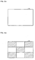
- FIG. 5A is a schematic diagram of a first calibration image according to an embodiment of the invention
- FIG 5B is a schematic diagram of a third calibration image according to an embodiment of the invention.
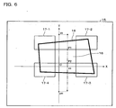
- FIG. 6 is a schematic diagram showing a first-stage search method when detecting center reference positions according to an embodiment of the invention.
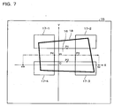
- FIG. 7 is a schematic diagram showing a second-stage search method when detecting center reference positions according to an embodiment of the invention.
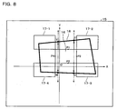
- FIG. 8 is a schematic diagram showing a first-stage search method when detecting peripheral reference positions according to an embodiment of the invention.
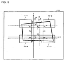
- FIG. 9 is a schematic diagram showing a second-stage search method when detecting peripheral reference positions according to an embodiment of the invention.
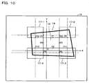
- FIG. 10 is a schematic diagram showing a third-stage search method when detecting peripheral reference positions according to an embodiment of the invention.
- FIG. 11 is a schematic diagram showing a method for setting approximation lines according to an embodiment of the invention.
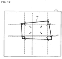
- FIG. 12 is a schematic diagram showing a search method when detecting a projection target area according to an embodiment of the invention.
- the present invention may provide an image processing system, a projector, an information storage medium, and an image processing method capable of appropriately detecting a predetermined area in a sensed image while reducing the effect of external light included in the sensed image.
- An image processing system and a projector according to embodiments of the invention comprise:
- An information storage medium stores a program for causing a computer to function as:
- An image processing method comprises:
- An image processing system and a projector according to embodiments of the invention comprise:
- An information storage medium stores a program for causing a computer to function as:
- An image processing method comprises:
- the image processing system and the like according to the embodiments of the invention can appropriately detect the projection target area in the sensed image in a state in which the effect of external light which causes a strong contrast is removed by performing a processing to remove the external light effect.
- the image processing system and the like according to the embodiments of the invention can detect the projection target area with higher accuracy by detecting the projection target area by performing edge detection and the like for the differential image from which the external light effect is removed.
- the first calibration image may be an image of which the entire image is white
- the second calibration image may be an image of which the entire image is black
- the brightness index value a value which is an index of brightness such as a luminance value or RGB signal values can be given.
- the differential image between the first calibration image or the planar light and the second calibration image or the planar light may be an image which does not include a high-frequency component.
- the image processing system and the like can perform highly accurate area detection in which erroneous detection rarely occurs.
- the image processing system and the projector of the embodiments of the invention may comprise:
- the information storage medium of the embodiments of the invention may stores a program for causing the computer to function as:
- the image processing method of the embodiment of the invention may comprise:
- the image processing system and the like can appropriately detect the projection area by using the second differential image, even if a part of the projected image (peripheral section, for example) is positioned outside the projection target.
- the image processing system and the projector of the embodiments of the invention may comprise:
- the information storage medium of the embodiments of the invention may stores a program for causing the computer to function as:
- the image processing method of the embodiment of the invention may comprise:
- the sensing section may generate the first sensing information by sensing the projection target at an automatic exposure, and may generate the second sensing information by sensing the projection target at an exposure determined by the automatic exposure for the first sensing information.
- the image processing method of the embodiment of the invention may comprise:
- the image processing system and the like can remove the effect of external light at a higher speed and a low load by using the differential image of the sensing information sensed at the same exposure.
- the invention is described below with reference to the drawings taking the case of applying the invention to a projector including an image processing system as an example. Note that the embodiments described hereunder do not in any way limit the scope of the invention defined by the claims laid out herein. Note also that not all of the elements of these embodiments should be taken as essential requirements to the means of the invention.
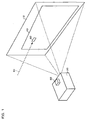
- FIG. 1 is a schematic diagram showing an image projection state according to an example of this embodiment.
- a projector 20 projects an image onto a screen 10 which is one type of projection target.
- a projected image 12 is displayed on the screen 10.
- This embodiment illustrates an example in which spot light 82 due to external light 80 (sunlight entering through an opening in a window shade, for example) is displayed on a part of the screen 10, and the peripheral section of the projected image 12 is displayed outside the screen 10, as shown in FIG. 1.
- the projector 20 includes a sensor 60 which is a sensing section.
- the sensor 60 generates sensing information by sensing the screen 10, on which the projected image 12 is displayed, through a sensing plane.
- the projector 20 determines the positional relationship between the screen 10 and the projected image 12 and the shape of the projected image 12 based on the sensing information, and adjusts distortion and the display position of the projected image 12.
- the projector 20 accurately generates positional information of the projection target area (area corresponding to the screen 10) and the projection area (area corresponding to the projected image 12) in the sensing area of the sensor 60 in a shorter period of time by performing image processing differing from conventional image processing.
- the projector 20 more accurately detects the projection target area and the like by removing the effect of the external light 80 included in the sensed image.
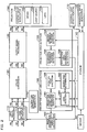
- FIG. 2 is a functional block diagram of the projector 20 according to an example of this embodiment.
- the projector 20 is configured to include an input signal processing section 110 which converts analog RGB signals (R1, G1, B1) input from a personal computer (PC) or the like into digital RGB signals (R2, G2, B2), a color conversion section 120 which converts the digital RGB signals (R2, G2, B2) into digital RGB signals (R3, G3, B3) in order to correct the color and brightness of an image, an output signal processing section 130 which converts the digital RGB signals (R3, G3, B3) into analog RGB signals (R4, G4, B4), and a projection section 190 which projects an image based on the analog RGB signals.
- an input signal processing section 110 which converts analog RGB signals (R1, G1, B1) input from a personal computer (PC) or the like into digital RGB signals (R2, G2, B2)
- a color conversion section 120 which converts the digital RGB signals (R2, G2, B2) into digital RGB signals (R3, G3, B3) in order to correct the color and brightness of an image
- an output signal processing section 130 which converts the digital RGB signals (R3, G3, B
- the projection section 190 is configured to include a spatial light modulator 192, a driver section 194 which drives the spatial light modulator 192, a light source 196, and a lens 198.
- the driver section 194 drives the spatial light modulator 192 based on the image signals from the output signal processing section 130.
- the projection section 190 projects light from the light source 196 through the spatial light modulator 192 and the lens 198.
- the projector 20 is configured to include a calibration information generation section 114 which generates calibration information for displaying first, second, and third calibration images, the sensor 60 which generates sensing information of the calibration image, and a storage section 140 which temporarily stores the sensing information from the sensor 60 and the like.
- the projector 20 is configured to include a differential image generation section 160 which generates a first differential image which is the difference between first and second sensed images and a second differential image which is the difference between first and third sensed images, and an external light effect removal section 170 which performs processing of removing the effect of external light.
- the projector 20 is configured to include a projection area detection section 150 which detects the position of the projection area on the sensing plane (sensing area) of the sensor 60.
- the projection area detection section 150 is configured to include a center reference position detection section 154 which detects a plurality of center reference positions of a center block area included in the differential image, a peripheral reference position detection section 156 which detects a plurality of peripheral reference positions of peripheral block areas included in the differential image, and a projection area information generation section 158 which generates projection area information which indicates the position of the projection area based on each reference position.
- the projector 20 includes a projection target area detection section 180 which generates projection target area information on the position of the projection target area corresponding to the screen 10 in the sensing area of the sensor 60.
- the projection target area detection section 180 is configured to include a search area determination section 182, an edge detection section 184, a detection point evaluation section 188 which evaluates edge detection points, and a projection target area information generation section 186 which generates provisional detection information by provisionally detecting the projection target area and generates the projection target area information.
- the projector 20 includes image distortion correction section which corrects distortion of the projected image 12.
- the projector 20 includes, as the image distortion correction section, an image distortion correction amount calculation section 162 which calculates an image distortion correction amount based on the projection area information and the projection target area information, and an image distortion correction section 112 which corrects the image signals based on the image distortion correction amount.
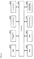
- FIG. 3 is a hardware block diagram of the projector 20 according to an example of this embodiment.
- the input signal processing section 110 may be implemented by using an A/D converter 930, an image processing circuit 970, or the like
- the storage section 140 may be implemented by using a RAM 950 or the like
- the projection area detection section 150, the differential image generation section 160, the external light effect removal section 170, and the projection target area detection section 180 may be implemented by using the image processing circuit 970 or the like
- the image distortion correction amount calculation section 162 may be implemented by using a CPU 910 or the like
- the calibration information generation section 114 may be implemented by using the image processing circuit 970, the RAM 950, or the like
- the output signal processing section 130 may be implemented by using a D/A converter 940 or the like
- the spatial light modulator 192 may be implemented by using a liquid crystal panel 920 or the like
- the driver section 194 may be implemented by using a ROM 960 which stores a liquid crystal light valve driver which drives the liquid crystal panel 920 or the like.
- These sections may be implemented by hardware such as a circuit, or may be implemented by software such as a driver.
- the function of the projection target area information generation section 186 or the like may be implemented by a computer by causing the computer to read a program from an information storage medium 900 which stores a program for causing the computer to function as the projection target area information generation section 186 or the like.
- the program reading method may be either a contact method or a noncontact method.
- the above-described functions may be implemented by downloading a program for implementing the above-described functions or the like from a host device or the like through a transmission line instead of using the information storage medium 900.
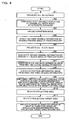
- FIG. 4 is a flowchart showing a flow of image processing according to an example of this embodiment.
- FIG 5A is a schematic diagram of the first calibration image according to an embodiment of the invention
- FIG 5B is a schematic diagram of the third calibration image according to this embodiment.
- the user installs the projector 20 facing the screen 10, and supplies power to the projector 20.
- the projector 20 projects an all-white image (entire image is white) 13 shown in FIG. 5A as the first calibration image (step S1).
- the calibration information generation section 114 generates calibration information (RGB signals, for example) for the all-white image 13, and the projection section 190 projects the all-white image 13 based on the calibration information.
- the sensor 60 generates first sensing information by sensing the all-white image 13 on the screen 10 at an automatic exposure setting (step S2).
- the storage section 140 stores the first sensing information.
- the projector 20 projects a pattern image 14 shown in FIG. 5B as the third calibration image (step S3).
- the pattern image 14 is a pattern image in a checkered pattern in which, when the entire image is equally divided into nine blocks, the center block area and four peripheral block areas at the four corners are black and the remaining block areas are white.
- the user confirms whether or not the center block area is positioned inside the frame of the screen 10.
- the user adjusts the position of the projector 20 or the like so that the center block area is positioned inside the frame of the screen 10, and restarts the projector 20 to allow the projector 20 to perform the processing in the steps S1 to S3 again.
- the sensor 60 generates third sensing information by sensing the pattern image 14 on the screen 10 in a state in which the center block area is positioned inside the frame of the screen 10 at the exposure when sensing the all-white image 13 (step S4).
- the storage section 140 stores the third sensing information.
- the projector 20 projects an all-black image (entire image is black) as the second calibration image (step S5).
- the sensor 60 generates second sensing information by sensing the all-black image on the screen 10 at the exposure when sensing the all-white image 13 (step S6).
- the storage section 140 stores the second sensing information.
- the differential image generation section 160 generates a black-and-white differential image which is the first differential image between the first sensed image indicated by the first sensing information and the second sensed image indicated by the second sensing information (step S7).
- the storage section 140 stores the black-and-white differential image.
- the differential image generation section 160 generates a pattern differential image which is the second differential image between the first sensed image and the third sensed image indicated by the third sensing information (step S8).
- the storage section 140 stores the pattern differential image.
- the external light effect removal section 170 judges whether or not a pixel area having a high luminance value (brightness index value equal to or greater than a predetermined value (200, for example)) exists in the second sensing information, and, when the pixel area exists, performs processing of replacing the luminance value (50, for example) of the pixel area in the black-and-white differential image with the luminance value (30, for example) in the vicinity of the pixel area in the black-and-white differential image (step S9).
- the projection area detection section 150 detects the projection area in the sensing area based on the pattern differential image (step S10). In more detail, the projection area detection section 150 detects a plurality (four in this embodiment) of center reference positions of the center block area included in the pattern differential image and a plurality (eight in this embodiment) of peripheral reference positions of the peripheral block areas included in the pattern differential image.
- FIG 6 is a schematic diagram showing a first-stage search method when detecting the center reference positions according to an example of this embodiment.
- FIG. 7 is a schematic diagram showing a second-stage search method when detecting the center reference positions according to an example of this embodiment.
- the center reference position detection section 154 detects four center reference positions of the pattern image in order to detect the position of the projection area (area corresponding to the projected image 12) in a sensing area 15 corresponding to the sensing plane.
- a projection target area 18 is provided in each drawing so that the description is readily understood. However, a part of the projection target area 18 or peripheral block areas 17-1 to 17-4 outside the projection target area 18 may not be included in the actual differential image.
- the value of the search reference position such as xc, yp, or ym may be determined by the angle of view and the position of the lens 198 and the sensor 60, or may be determined by experiments, or may be determined corresponding to the sensing result. This also applies to other search reference positions described later.
- yc equals (y1 + y2)/2, for example.
- the center reference position detection section 154 outputs center reference positional information which indicates the four center reference positions P1(xc, y1), P2(xc, y2), P3(x1, yc), and P4(x2, yc) of the center block area 16 to the peripheral reference position detection section 156.
- the peripheral reference position detection section 156 detects eight peripheral reference positions of the pattern image based on the center reference positional information.
- FIG 8 is a schematic diagram showing a first-stage search method when detecting the peripheral reference positions according to an example of this embodiment.
- FIG 9 is a schematic diagram showing a second-stage search method when detecting the peripheral reference positions according to an example of this embodiment.
- FIG 10 is a schematic diagram showing a third-stage search method when detecting the peripheral reference positions according to an example of this embodiment.
- the edge detection section 184 of the projection target area detection section 180 performs edge detection in pixel units for the black-and-white differential image as the search target based on the center reference positions P1 to P4 of the center block area 16 outward from the Y-coordinatc points y1 and y2 of the center reference positions P1 and P2 on additional search lines which exist inside the center block area 16 in the horizontal direction at a predetermined percentage from each of the center reference positions P3 and P4. As a result, four edge detection points Z, U, V, and W are detected.
- a method of detecting the edge using a filter for a plurality of pixels a method of detecting the luminance value as the edge in pixel units without using a filter, or the like may be employed.
- the peripheral reference position detection section 156 calculates a Y-coordinate value yP which is the value obtained by adding a value at a predetermined percentage of the distance (differential value) between the smaller of the Y-coordinate value yZ of the point Z and the Y-coordinate value yU of the point U and the Y-coordinate value yl of the center reference position Pl to the Y-coordinate value yl.
- the peripheral reference position detection section 156 calculates a Y-coordinate value yQ which is the value obtained by subtracting a value at a predetermined percentage of the distance between the larger of the Y-coordinate value yV of the point V and the Y-coordinate value yW of the point W and the Y-coordinate value y2 of the center reference position P2 from the Y-coordinate value y2.
- the peripheral reference position detection section 156 calculates an X-coordinate value xR at a position inside the center block area 16 in the horizontal direction at a predetermined percentage from the X-coordinate value xZ of the point Z and the point W.
- the peripheral reference position detection section 156 calculates an X-coordinate value xS at a position inside the center block area 16 in the horizontal direction at a predetermined percentage from the X-coordinate value xU of the point U and the point V.
- the peripheral reference position detection section 156 determines four points P9 to P12 existing on the horizontal side of each of the peripheral block areas 17-1 to 17-4 on the side of the center block area 16 by using the same method as described above.
- the peripheral reference position detection section 156 outputs peripheral reference positional information which indicates the coordinates of these eight points and the center reference positional information to the projection area information generation section 158.
- the projection area information generation section 158 detects the positions of four corners of the projection area by using approximation lines (may be approximation curves) based on the peripheral reference positional information and the center reference positional information.
- FIG. 11 is a schematic diagram showing a method for setting approximation lines according to an example of this embodiment.
- the projection area information generation section 158 sets an approximation line indicated by the dashed line shown in FIG 10 based on the coordinates of the points P5, P3, and P6.
- the projection area information generation section 158 sets four approximation lines indicated by the dashed lines as shown in FIG. 1 X by using the same method as described above, and determines four intersecting points A(xA, yA) to D(xD, yD) of each approximation line as four corner points of the center block area 16.
- the projection area information generation section 158 outputs projection area information which indicates the four corner points E, F, G, and H of the projection area corresponding to the projected image 12 to the image distortion correction amount calculation section 162 by using the above-described method.
- the projection target area detection section 180 detects the projection target area 18 in the sensing area 15 based on the black-and-white differential image (step S11).
- the position detection processing of the projection target area 18 is described below.
- FIG. 12 is a schematic diagram showing a search method when detecting the projection target area according to an example of this embodiment.
- the search area determination section 182 sets four additional search lines which pass outside the area ABCD to some extent based on the black-and-white differential image and the coordinate information of the four corners A, B, C, and D of the center block area 16.
- the search area determination section 182 sets the additional search lines for the black-and-white differential image at positions p% outside the coordinates of the four corners A, B, C, and D of the center block area 16 detected by the center reference position detection section 154.
- the symbols max, min, and round respectively indicate a function which returns the maximum value of the arguments, a function which returns the minimum value of the arguments, and a function which returns an integer obtained by rounding off the argument to the nearest whole number.
- four intersecting points I, J, K, and L of the four additional search lines are determined by setting the four additional search lines as described above.
- the edge detection section 184 performs edge detection for the black-and-white differential image as the search target in pixel units on search lines on the additional search lines toward the outside of the area IJKL from each of the intersecting points I, J, K, and L. As a result, eight edge detection points M, N, O, P, Q, R, S, and T are detected as shown in FIG 12.
- the edge detection section 184 performs edge detection in pixel units in each of the direction from the line segment TO toward the borderline of the projection target area 18, the direction from the line segment NQ toward the borderline of the projection target area 18, the direction from the line segment PS toward the borderline of the projection target area 18, and the direction from the line segment RM toward the borderline of the projection target area 18.
- the edge detection section 184 performs edge detection from the line segment TO in parallel to the Y axis and in the positive direction, for example.
- the edge detection section 184 sets seven search lines for the line segment 1J, and sets two search lines for each of the line segments TI and JO.
- the area in which the seven search lines arc set is called an inner search area, and each of the two areas in which the two search lines are set is called an outer search area.
- the edge detection section 184 can detect 11 edge detection points at maximum (13 edge detection points at maximum including the points M and N) on the straight line MN by performing edge detection on the search lines in pixel units.
- the edge detection section 184 performs edge detection for the remaining line segment NQ, line segment PS, and line segment RM in the same manner as described above.
- the edge detection section 184 determines that the borderline of the projection target area 18 does not exist in the outer search area for searching for the undetected point, and does not set the search line or perform edge detection in that area. In the case where both points of each pair of the edge detection points MN, OP, QR, and ST cannot be detected in the sensing area 15, the edge detection section 184 determines that the borderline of the projection target area 18 adjacent to the undetected line segment in parallel does not exist, and does not set the search line or perform edge detection in the inner search area and the outer search area for searching for the undetected line segment.
- the edge detection section 184 can omit edge detection for the area in which the projection target area 18 exists with low possibility by performing the above processing, whereby the processing can be performed at higher speed.
- the projection target area information generation section 186 preliminarily determines the projection target area 18 by setting linear approximation lines or linear approximation curves based on the edge detection points detected by the edge detection section 184.
- the detection point evaluation section 188 evaluates each edge detection point by judging whether or not each edge detection point detected by the edge detection section 184 is separated from the linear approximation line or linear approximation curve set by the projection target are information generation section 186 at a value equal to or greater than a predetermined value.
- the projection target area information generation section 186 detects the projection target area 18 with higher accuracy by using only the edge detection points which are not excluded from the processing target.
- the edge detection section 184 performs edge detection for peripheral pixels of the edge detection points which are not excluded from the processing target based on the black-and-white differential image.
- the edge detection section 184 outputs edge detection information to the projection target area information generation section 186.
- the projection target area information generation section 186 determines the projection target area 18 by again setting linear approximation lines or linear approximation curves based on the edge detection information.
- the projection target area information generation section 186 generates the projection target area information which indicates the positions of four corners of the projection target area 18, and outputs the projection target area information to the image distortion correction amount calculation section 162.
- the projector 20 projects an image so that distortion of the projected image 12 is corrected based on the projection area information and the projection target area information (step S12).
- the image distortion correction amount calculation section 162 determines the positional relationship and the shape of the screen 10 and the projected image 12 based on the projection area information from the projection area information generation section 158 and the projection target area information from the projection target area information generation section 186, and calculates the image distortion correction amount so that distortion of the projected image 12 is corrected and the projected image 12 has a desired aspect ratio (height/width ratio).
- the image distortion correction section 112 corrects the image signals (R1, G1, B1) based on the image distortion correction amount. This enables the projector 20 to project an image without distortion while maintaining a desired aspect ratio.
- the image distortion correction method is not limited to this method.
- the projector 20 may detect a pixel having the greatest luminance value in the sensed image, and correct distortion of the image based on the position of the pixel.
- the projector 20 can appropriately detect the projection target area 18 in the sensed image in a state in which the effect of the external light 80 which causes a strong contrast is removed by performing the external light effect removal processing.
- the projector 20 can detect the projection target area 18 or the like with higher accuracy by detecting the projection target area 18 or the like by performing edge detection or the like for the differential image from which the external light effect is removed.
- the projector 20 can accurately generate the positional information of the projection target area 18 in a shorter period of time by preliminarily detecting the projection target area 18 and detecting the vicinity of the borderline of the projection target area 18. This reduces the amount of calculation processing of the entire image processing system, whereby the projector 20 can perform high-speed image processing at a low load.
- the projector 20 can generate the positional information of the projection target area 18 in a shorter period of time by performing edge detection in a state in which the edge detection target area is reduced.
- the projector 20 can reduce the effect of noise or the like by performing the processing while excluding the edge detection point separated from the linear approximation line or the like, whereby the positional information of the projection target area 18 can be generated more accurately.
- the projector 20 can more accurately determine the four corners of the projection area in comparison with the case of using a pattern image having features only at the center by using an image having features not only at the center but also on the periphery as in the pattern image 14 shown in FIG. 5B.
- the projector 20 can also determine points near the points P1 and P2 at which the luminance value changes.
- the approximation line is affected to a large extent by an error of one pixel at the point which makes up the approximation line in comparison with the case.of setting the approximation line using the points located at large intervals.
- the projector 20 can set the approximation lines using the points located at large intervals by using the reference points of the center block area 16 and the reference points of the peripheral block areas 17-1 to 17-4, the projector 20 can more accurately determine the four corners of the projection area.
- the projector 20 can appropriately detect the projection area by using the pattern image 14, even if the peripheral section of the projected image 12 is displayed outside the screen 10.
- the projector 20 can more easily detect the position of the projection area at high speed by searching for only a necessary area of the differential image instead of searching for the entire differential image.
- the projector 20 can generate the first sensing information at an exposure conforming to the application environment by generating the first sensing information by sensing the all-white image at the automatic exposure setting when projecting the calibration image.
- the projector 20 can generate the second and third sensing information at an exposure suitable for generating the differential image by generating the second and third sensing information at the exposure when sensing the all-white image.
- the sensor 60 can sense the image by effectively utilizing the dynamic range of the sensor 60 by sensing the all-white image at the automatic exposure setting in comparison with the case of sensing the image at a fixed exposure, even when the screen 10 is affected by the external light 80, when the reflected projection light is too weak since the projection distance is too great or the reflectivity of the screen 10 is too low, and when the reflected projection light is too strong since the projection distance is too small or the reflectivity of the screen 10 is too high.
- the external light effect removal section 170 performs the processing of replacing the luminance value of the pixel area in the black-and-white differential image with the luminance value in the vicinity of the pixel area in the black-and-white differential image.
- a special value 300, for example may be set as the luminance value of the pixel area in the black-and-white differential image or the pattern differential image so that the edge detection processing is not performed.
- the edge detection section 184 When the edge detection section 184 has detected the special value, the edge detection section 184 performs processing of invalidating the edge detection result of the area.
- the center reference position detection section 154 or the peripheral reference position detection section 156 When the center reference position detection section 154 or the peripheral reference position detection section 156 has detected the special value, the center reference position detection section 154 or the peripheral reference position detection section 156 performs processing of excluding the area from the center reference position or the peripheral reference position.
- the projection target area detection section 180 or the projection area detection section 150 may perform the detection processing while ignoring, invalidating, or removing the pixel area.
- the projector 20 can also remove the external light effect by such processing.
- the senor 60 generates the second sensing information by using the all-black image.
- the sensor 60 may generate the second sensing information by sensing the screen 10 when an image is not projected.
- the external light effect removal section 170 may perform the external light effect removal processing for the pattern differential image as the processing target.
- the differential image generation section 160 may use the differential image between the all-black image and the pattern image 14 as the pattern differential image.
- the sensor 60 may generate the first or second sensing information by sensing the screen 10 in a state in which the projection section 190 projects planar light onto the screen 10 from the light source 196 in a state in which the image signal is not input.
- the projector 20 does not necessarily project the all-white image 13 or the all-black image.
- the positional relationship between the projected image 12 and the screen 10 is not limited to the example shown in FIG 1.
- the entire outer frame of the projected image 12 may be located outside or inside of the outer frame of the screen 10.
- the projector 20 may adjust the position of the projected image 12 using the projection area information and the projection target area information, detect the indication position in the projected image 12 using a laser pointer or the like, or correct the color non-uniformity of the projected image 12 using the projection target area information, for example.
- the search procedure is arbitrary.
- the projector 20 may detect the center reference positions or the peripheral reference positions by searching for the differential image in the horizontal direction, and search for the differential image in the vertical direction based on the center reference positions or the peripheral reference positions.
- the projector 20 may detect the projection area after detecting the projection target area 18.
- the pattern image 14 is not limited to that in the above-described embodiment.
- the pattern differential image may be an image having a pattern similar to that of the pattern image 14.
- the first calibration image may be an image having the center block area 16
- the third calibration image may be an image having the peripheral block areas 17-1 to 17-4.
- the shape of the center block area 16 and the peripheral block areas 17-1 to 17-4 is not limited to quadrilateral.
- a shape other than quadrilateral such as a circle may be employed.
- the shape of the entire calibration image and the shape of the center block area 16 may not be similar. It suffices that the calibration image and the center block area 16 have a shape which allows the correspondence between the shape of the calibration image and the shape of the center block area 16 to be identified.
- the number of the peripheral block areas 17-1 to 17-4 is also arbitrary.
- the order of projection and sensing of the all-white image 13, the all-black image, and the pattern image 14 is arbitrary.
- the projector 20 may perform the processing in the steps S1 to S6 after projecting the pattern image 14 and allowing the user to confirm whether or not the center block area is positioned inside the screen 10, or may project and sense the pattern image 14 after projecting and sensing the all-black image.
- the invention is also effective even when projecting an image onto a projection target other than the screen 10, such as a blackboard or a whiteboard.
- the above-described embodiment illustrates an example in which the image processing system is provided to the projector 20.
- the image processing system may be provided to an image display device other than the projector 20, such as a cathode ray tube (CRT).
- CRT cathode ray tube
- a projector using a digital micromirror device (DMD) or the like may be used in addition to the liquid crystal projector.
- DMD is a trademark of Texas Instruments, Inc. (USA.).
- the function of the projector 20 may be implemented by only a projector, or may be distributed over a plurality of processing devices (distribution processing by projector and PC, for example).
- the senor 60 is included in the projector 20.
- the sensor 60 may be configured as a device independent of the projector 20.
Landscapes
- Engineering & Computer Science (AREA)
- Multimedia (AREA)
- Signal Processing (AREA)
- Physics & Mathematics (AREA)
- Geometry (AREA)
- General Physics & Mathematics (AREA)
- Theoretical Computer Science (AREA)
- Projection Apparatus (AREA)
- Image Processing (AREA)
- Transforming Electric Information Into Light Information (AREA)
- Controls And Circuits For Display Device (AREA)
Abstract
A projector includes a projection section which projects an all-white image and an all-black image onto a screen, a sensor which generates first sensing information by sensing the all-white image and generates second sensing information by sensing the all-black image, a differential image generation section which generates a differential image based on the first and second sensing information, an external light effect removal section, and a projection target area detection section which generates projection target arca information on the position of a projection target area corresponding to the screen in the sensing area of the sensor based on the differential image from which the external light effect is removed. <IMAGE>
Description
The present invention relates to an image processing system, a projector, an
information storage medium, and an image processing method that detect a
predetermined area based on sensing information.
In recent years, a method of adjusting the position of a projected image by
projecting an image onto a projection target such as a screen using a projector including
a CCD camera, sensing the projected image using the CCD camera, and detecting the
coordinates of four corners of the projection area in the sensing area has been proposed.
In this case, if external light which causes a strong contrast, such as sunlight
entering through a window shade, is reflected on the screen, the external light may be
judged as an edge or a part of a shape during edge detection or shape detection.
To deal with this problem, Japanese Patent Application Laid-open No.
2001-268326 proposes an image processing device which removes the effect of external
light components on a sensed image.
However, the effect of external light which causes a strong contrast cannot be
removed by utilizing a method using a general differential image as that of the image
processing device disclosed in Japanese Patent Application Laid-open No. 2001-268326.
This is because the sensed image becomes saturated due to the addition of the effect of
external light to the projection light.
The image processing device disclosed in Japanese Patent Application
Laid-open No. 2001-268326 aims at removing the effect of external light after edge
detection based on external light information near the edge or the like. However, since
the edge due to external light which causes a strong contrast differs to a large extent
from the area near the edge, the effect of external light cannot be appropriately removed
by using this method.
The image processing device disclosed in Japanese Patent Application
Laid-open No. 2001-268326 performs processing by obtaining the exposure. However,
since the exposure is determined based on the average brightness of the entire image,
the effect cannot be appropriately judged when a strong contrast occurs on a part of an
image due to external light.
In the case where a projector projects an image onto a screen or the like, it is
preferable that distortion of the projected image be corrected irrespective of the
inclusion relationship between the projected image and the screen, even when the effect
of external light occurs.
A first aspect of the present invention relates to an image processing system,
comprising:
A second aspect of the invention relates to an image processing system,
comprising:
A third aspect of the invention relates to a projector comprising:
A fourth aspect of the invention relates to an information storage medium which
stores a program for causing a computer to function as:
A fifth aspect of the invention relates to an image processing method
comprising:
FIG 1 is a schematic diagram showing an image projection state according to an
embodiment of the present invention.
FIG. 2 is a functional block diagram of a projector according to an embodiment
of the invention.
FIG. 3 is a hardware block diagram of a projector according to an embodiment
of the invention.
FIG. 4 is a flowchart showing a flow of image processing according to an
embodiment of the invention.
FIG. 5A is a schematic diagram of a first calibration image according to an
embodiment of the invention, and FIG 5B is a schematic diagram of a third calibration
image according to an embodiment of the invention.
FIG. 6 is a schematic diagram showing a first-stage search method when
detecting center reference positions according to an embodiment of the invention.
FIG. 7 is a schematic diagram showing a second-stage search method when
detecting center reference positions according to an embodiment of the invention.
FIG. 8 is a schematic diagram showing a first-stage search method when
detecting peripheral reference positions according to an embodiment of the invention.
FIG. 9 is a schematic diagram showing a second-stage search method when
detecting peripheral reference positions according to an embodiment of the invention.
FIG. 10 is a schematic diagram showing a third-stage search method when
detecting peripheral reference positions according to an embodiment of the invention.
FIG. 11 is a schematic diagram showing a method for setting approximation
lines according to an embodiment of the invention.
FIG. 12 is a schematic diagram showing a search method when detecting a
projection target area according to an embodiment of the invention.
The present invention may provide an image processing system, a projector, an
information storage medium, and an image processing method capable of appropriately
detecting a predetermined area in a sensed image while reducing the effect of external
light included in the sensed image.
An image processing system and a projector according to embodiments of the
invention comprise:
An information storage medium according to an embodiment of the invention
stores a program for causing a computer to function as:
An image processing method according to an embodiment of the invention
comprises:
An image processing system and a projector according to embodiments of the
invention comprise:
An information storage medium according to an embodiment of the invention
stores a program for causing a computer to function as:
An image processing method according to an embodiment of the invention
comprises:
The image processing system and the like according to the embodiments of the
invention can appropriately detect the projection target area in the sensed image in a
state in which the effect of external light which causes a strong contrast is removed by
performing a processing to remove the external light effect.
The image processing system and the like according to the embodiments of the
invention can detect the projection target area with higher accuracy by detecting the
projection target area by performing edge detection and the like for the differential
image from which the external light effect is removed.
The first calibration image may be an image of which the entire image is white,
and the second calibration image may be an image of which the entire image is black.
As the brightness index value, a value which is an index of brightness such as a
luminance value or RGB signal values can be given.
The differential image between the first calibration image or the planar light and
the second calibration image or the planar light may be an image which does not include
a high-frequency component.
According to this feature, the image processing system and the like can perform
highly accurate area detection in which erroneous detection rarely occurs.
The image processing system and the projector of the embodiments of the
invention may comprise:
The information storage medium of the embodiments of the invention may
stores a program for causing the computer to function as:
The image processing method of the embodiment of the invention may
comprise:
According to this feature, the image processing system and the like can
appropriately detect the projection area by using the second differential image, even if a
part of the projected image (peripheral section, for example) is positioned outside the
projection target.
The image processing system and the projector of the embodiments of the
invention may comprise:
The information storage medium of the embodiments of the invention may
stores a program for causing the computer to function as:
The image processing method of the embodiment of the invention may
comprise:
This enables the image processing system and the like to appropriately correct
distortion of an image even if the effect of external light occurs.
With the image processing system, the projector and the information storage
medium of the embodiments of the invention,
the sensing section may generate the first sensing information by sensing the projection target at an automatic exposure, and may generate the second sensing information by sensing the projection target at an exposure determined by the automatic exposure for the first sensing information.
the sensing section may generate the first sensing information by sensing the projection target at an automatic exposure, and may generate the second sensing information by sensing the projection target at an exposure determined by the automatic exposure for the first sensing information.
The image processing method of the embodiment of the invention may
comprise:
According to this feature, the image processing system and the like can remove
the effect of external light at a higher speed and a low load by using the differential
image of the sensing information sensed at the same exposure. The invention is
described below with reference to the drawings taking the case of applying the
invention to a projector including an image processing system as an example. Note
that the embodiments described hereunder do not in any way limit the scope of the
invention defined by the claims laid out herein. Note also that not all of the elements of
these embodiments should be taken as essential requirements to the means of the
invention.
FIG. 1 is a schematic diagram showing an image projection state according to an
example of this embodiment.
A projector 20 projects an image onto a screen 10 which is one type of
projection target. As a result, a projected image 12 is displayed on the screen 10.
This embodiment illustrates an example in which spot light 82 due to external light 80
(sunlight entering through an opening in a window shade, for example) is displayed on a
part of the screen 10, and the peripheral section of the projected image 12 is displayed
outside the screen 10, as shown in FIG. 1.
The projector 20 includes a sensor 60 which is a sensing section. The sensor
60 generates sensing information by sensing the screen 10, on which the projected
image 12 is displayed, through a sensing plane. The projector 20 determines the
positional relationship between the screen 10 and the projected image 12 and the shape
of the projected image 12 based on the sensing information, and adjusts distortion and
the display position of the projected image 12.
The projector 20 accurately generates positional information of the projection
target area (area corresponding to the screen 10) and the projection area (area
corresponding to the projected image 12) in the sensing area of the sensor 60 in a
shorter period of time by performing image processing differing from conventional
image processing.
The projector 20 more accurately detects the projection target area and the like
by removing the effect of the external light 80 included in the sensed image.
Functional blocks of the projector 20 for implementing such functions are
described below.
FIG. 2 is a functional block diagram of the projector 20 according to an example
of this embodiment.
The projector 20 is configured to include an input signal processing section 110
which converts analog RGB signals (R1, G1, B1) input from a personal computer (PC)
or the like into digital RGB signals (R2, G2, B2), a color conversion section 120 which
converts the digital RGB signals (R2, G2, B2) into digital RGB signals (R3, G3, B3) in
order to correct the color and brightness of an image, an output signal processing
section 130 which converts the digital RGB signals (R3, G3, B3) into analog RGB
signals (R4, G4, B4), and a projection section 190 which projects an image based on the
analog RGB signals.
The projection section 190 is configured to include a spatial light modulator 192,
a driver section 194 which drives the spatial light modulator 192, a light source 196, and
a lens 198. The driver section 194 drives the spatial light modulator 192 based on the
image signals from the output signal processing section 130. The projection section
190 projects light from the light source 196 through the spatial light modulator 192 and
the lens 198.
The projector 20 is configured to include a calibration information generation
section 114 which generates calibration information for displaying first, second, and
third calibration images, the sensor 60 which generates sensing information of the
calibration image, and a storage section 140 which temporarily stores the sensing
information from the sensor 60 and the like.
The projector 20 is configured to include a differential image generation section
160 which generates a first differential image which is the difference between first and
second sensed images and a second differential image which is the difference between
first and third sensed images, and an external light effect removal section 170 which
performs processing of removing the effect of external light.
The projector 20 is configured to include a projection area detection section 150
which detects the position of the projection area on the sensing plane (sensing area) of
the sensor 60. The projection area detection section 150 is configured to include a
center reference position detection section 154 which detects a plurality of center
reference positions of a center block area included in the differential image, a peripheral
reference position detection section 156 which detects a plurality of peripheral reference
positions of peripheral block areas included in the differential image, and a projection
area information generation section 158 which generates projection area information
which indicates the position of the projection area based on each reference position.
The projector 20 includes a projection target area detection section 180 which
generates projection target area information on the position of the projection target area
corresponding to the screen 10 in the sensing area of the sensor 60. The projection
target area detection section 180 is configured to include a search area determination
section 182, an edge detection section 184, a detection point evaluation section 188
which evaluates edge detection points, and a projection target area information
generation section 186 which generates provisional detection information by
provisionally detecting the projection target area and generates the projection target area
information.
The projector 20 includes image distortion correction section which corrects
distortion of the projected image 12. In more detail, the projector 20 includes, as the
image distortion correction section, an image distortion correction amount calculation
section 162 which calculates an image distortion correction amount based on the
projection area information and the projection target area information, and an image
distortion correction section 112 which corrects the image signals based on the image
distortion correction amount.
As hardware for implementing the function of each section of the projector 20,
the following hardware may be applied, for example.
FIG. 3 is a hardware block diagram of the projector 20 according to an example
of this embodiment.
For example, the input signal processing section 110 may be implemented by
using an A/D converter 930, an image processing circuit 970, or the like, the storage
section 140 may be implemented by using a RAM 950 or the like, the projection area
detection section 150, the differential image generation section 160, the external light
effect removal section 170, and the projection target area detection section 180 may be
implemented by using the image processing circuit 970 or the like, the image distortion
correction amount calculation section 162 may be implemented by using a CPU 910 or
the like, the calibration information generation section 114 may be implemented by
using the image processing circuit 970, the RAM 950, or the like, the output signal
processing section 130 may be implemented by using a D/A converter 940 or the like,
the spatial light modulator 192 may be implemented by using a liquid crystal panel 920
or the like, and the driver section 194 may be implemented by using a ROM 960 which
stores a liquid crystal light valve driver which drives the liquid crystal panel 920 or the
like.
These sections can exchange information through a system bus 980.
These sections may be implemented by hardware such as a circuit, or may be
implemented by software such as a driver.
The function of the projection target area information generation section 186 or
the like may be implemented by a computer by causing the computer to read a program
from an information storage medium 900 which stores a program for causing the
computer to function as the projection target area information generation section 186 or
the like.
As the information storage medium 900, a CD-ROM, DVD-ROM, ROM, RAM,
HDD, or the like may be applied. The program reading method may be either a
contact method or a noncontact method.
The above-described functions may be implemented by downloading a program
for implementing the above-described functions or the like from a host device or the
like through a transmission line instead of using the information storage medium 900.
Image processing using these sections is described below.
FIG. 4 is a flowchart showing a flow of image processing according to an
example of this embodiment. FIG 5A is a schematic diagram of the first calibration
image according to an embodiment of the invention, and FIG 5B is a schematic diagram
of the third calibration image according to this embodiment.
The user installs the projector 20 facing the screen 10, and supplies power to the
projector 20.
The projector 20 projects an all-white image (entire image is white) 13 shown in
FIG. 5A as the first calibration image (step S1). In more detail, the calibration
information generation section 114 generates calibration information (RGB signals, for
example) for the all-white image 13, and the projection section 190 projects the
all-white image 13 based on the calibration information.
The sensor 60 generates first sensing information by sensing the all-white image
13 on the screen 10 at an automatic exposure setting (step S2). The storage section
140 stores the first sensing information.
The projector 20 projects a pattern image 14 shown in FIG. 5B as the third
calibration image (step S3). The pattern image 14 is a pattern image in a checkered
pattern in which, when the entire image is equally divided into nine blocks, the center
block area and four peripheral block areas at the four corners are black and the
remaining block areas are white.
The user confirms whether or not the center block area is positioned inside the
frame of the screen 10. When the center block area is not positioned inside the frame
of the screen 10, the user adjusts the position of the projector 20 or the like so that the
center block area is positioned inside the frame of the screen 10, and restarts the
projector 20 to allow the projector 20 to perform the processing in the steps S1 to S3
again.
The sensor 60 generates third sensing information by sensing the pattern image
14 on the screen 10 in a state in which the center block area is positioned inside the
frame of the screen 10 at the exposure when sensing the all-white image 13 (step S4).
The storage section 140 stores the third sensing information.
The projector 20 projects an all-black image (entire image is black) as the
second calibration image (step S5).
The sensor 60 generates second sensing information by sensing the all-black
image on the screen 10 at the exposure when sensing the all-white image 13 (step S6).
The storage section 140 stores the second sensing information.
The differential image generation section 160 generates a black-and-white
differential image which is the first differential image between the first sensed image
indicated by the first sensing information and the second sensed image indicated by the
second sensing information (step S7). The storage section 140 stores the
black-and-white differential image.
The differential image generation section 160 generates a pattern differential
image which is the second differential image between the first sensed image and the
third sensed image indicated by the third sensing information (step S8). The storage
section 140 stores the pattern differential image.
The external light effect removal section 170 judges whether or not a pixel area
having a high luminance value (brightness index value equal to or greater than a
predetermined value (200, for example)) exists in the second sensing information, and,
when the pixel area exists, performs processing of replacing the luminance value (50,
for example) of the pixel area in the black-and-white differential image with the
luminance value (30, for example) in the vicinity of the pixel area in the
black-and-white differential image (step S9).
The effect of the external light 80 in the black-and-white differential image is
removed by this processing.
The projection area detection section 150 detects the projection area in the
sensing area based on the pattern differential image (step S10). In more detail, the
projection area detection section 150 detects a plurality (four in this embodiment) of
center reference positions of the center block area included in the pattern differential
image and a plurality (eight in this embodiment) of peripheral reference positions of the
peripheral block areas included in the pattern differential image.
FIG 6 is a schematic diagram showing a first-stage search method when
detecting the center reference positions according to an example of this embodiment.
FIG. 7 is a schematic diagram showing a second-stage search method when detecting
the center reference positions according to an example of this embodiment.
The center reference position detection section 154 detects four center reference
positions of the pattern image in order to detect the position of the projection area (area
corresponding to the projected image 12) in a sensing area 15 corresponding to the
sensing plane. A projection target area 18 is provided in each drawing so that the
description is readily understood. However, a part of the projection target area 18 or
peripheral block areas 17-1 to 17-4 outside the projection target area 18 may not be
included in the actual differential image.
In more detail, the center reference position detection section 154 determines
points P1 and P2 at which the differential value changes by searching for the differential
value in the differential image at the vertical position x = xc at which the center block
area 16 is expected to be positioned from y = yp to y = ym in pixel units, as shown in
FIG 6. For example, suppose that P1 is (xc, yl) and P2 is (xc, y2).
The value of the search reference position such as xc, yp, or ym may be
determined by the angle of view and the position of the lens 198 and the sensor 60, or
may be determined by experiments, or may be determined corresponding to the sensing
result. This also applies to other search reference positions described later.
As shown in FIG 7, the center reference position detection section 154
determines points P4 and P3 at which the differential value changes by searching for the
differential value from x = xm to x = xp in pixel units at the horizontal position y = yc
based on the points P1 and P2. yc equals (y1 + y2)/2, for example.
The center reference position detection section 154 outputs center reference
positional information which indicates the four center reference positions P1(xc, y1),
P2(xc, y2), P3(x1, yc), and P4(x2, yc) of the center block area 16 to the peripheral
reference position detection section 156.
The peripheral reference position detection section 156 detects eight peripheral
reference positions of the pattern image based on the center reference positional
information.
FIG 8 is a schematic diagram showing a first-stage search method when
detecting the peripheral reference positions according to an example of this embodiment.
FIG 9 is a schematic diagram showing a second-stage search method when detecting
the peripheral reference positions according to an example of this embodiment. FIG
10 is a schematic diagram showing a third-stage search method when detecting the
peripheral reference positions according to an example of this embodiment.
The edge detection section 184 of the projection target area detection section
180 performs edge detection in pixel units for the black-and-white differential image as
the search target based on the center reference positions P1 to P4 of the center block
area 16 outward from the Y-coordinatc points y1 and y2 of the center reference
positions P1 and P2 on additional search lines which exist inside the center block area
16 in the horizontal direction at a predetermined percentage from each of the center
reference positions P3 and P4. As a result, four edge detection points Z, U, V, and W
are detected.
As the method for the edge detection processing, a method of detecting the edge
using a filter for a plurality of pixels, a method of detecting the luminance value as the
edge in pixel units without using a filter, or the like may be employed.
The peripheral reference position detection section 156 calculates a Y-coordinate
value yP which is the value obtained by adding a value at a predetermined percentage of
the distance (differential value) between the smaller of the Y-coordinate value yZ of the
point Z and the Y-coordinate value yU of the point U and the Y-coordinate value yl of
the center reference position Pl to the Y-coordinate value yl. The peripheral reference
position detection section 156 calculates a Y-coordinate value yQ which is the value
obtained by subtracting a value at a predetermined percentage of the distance between
the larger of the Y-coordinate value yV of the point V and the Y-coordinate value yW of
the point W and the Y-coordinate value y2 of the center reference position P2 from the
Y-coordinate value y2.
The peripheral reference position detection section 156 calculates an
X-coordinate value xR at a position inside the center block area 16 in the horizontal
direction at a predetermined percentage from the X-coordinate value xZ of the point Z
and the point W. The peripheral reference position detection section 156 calculates an
X-coordinate value xS at a position inside the center block area 16 in the horizontal
direction at a predetermined percentage from the X-coordinate value xU of the point U
and the point V.
The peripheral reference position detection section 156 determines four points
P5 to P8 existing on the side of each of the peripheral block areas 17-1 to 17-4 on the
side of the center block area 16 by searching for the pattern differential image on the
lines Y = yP and Y = yQ outward from the intersecting points of the four straight lines X
= xR, X = xS, Y = -yP, and Y = yQ (dash-dot-dot lines shown in FIG. 9) to detect pixels
having an output. The peripheral reference position detection section 156 determines
four points P9 to P12 existing on the horizontal side of each of the peripheral block
areas 17-1 to 17-4 on the side of the center block area 16 by using the same method as
described above.
The peripheral reference position detection section 156 outputs peripheral
reference positional information which indicates the coordinates of these eight points
and the center reference positional information to the projection area information
generation section 158.
The projection area information generation section 158 detects the positions of
four corners of the projection area by using approximation lines (may be approximation
curves) based on the peripheral reference positional information and the center
reference positional information.
FIG. 11 is a schematic diagram showing a method for setting approximation
lines according to an example of this embodiment.
The projection area information generation section 158 sets an approximation
line indicated by the dashed line shown in FIG 10 based on the coordinates of the points
P5, P3, and P6. The projection area information generation section 158 sets four
approximation lines indicated by the dashed lines as shown in FIG. 1 X by using the same
method as described above, and determines four intersecting points A(xA, yA) to D(xD,
yD) of each approximation line as four corner points of the center block area 16.
Since the center block area 16 is the area corresponding to an image obtained by
reducing the original projected image 12 by 1/9, four corner points E, F, q and H of the
projection area corresponding to the projected image 12 are expressed as follows.
Specifically, E(xE, yE) = (2 * xA - xC, 2 * yA - yc), F(xF, yF) = (2 * xB - xD, 2 * yB -
yD), G(xG, yG) = (2 * xC - xA, 2 * yC - yA), and H(xH, yH) = (2 * xD - xB, 2 * yD -
yB).
The projection area information generation section 158 outputs projection area
information which indicates the four corner points E, F, G, and H of the projection area
corresponding to the projected image 12 to the image distortion correction amount
calculation section 162 by using the above-described method.
The projection target area detection section 180 detects the projection target area
18 in the sensing area 15 based on the black-and-white differential image (step S11).
The position detection processing of the projection target area 18 is described below.
FIG. 12 is a schematic diagram showing a search method when detecting the
projection target area according to an example of this embodiment.
In order to determine the edge detection target, the search area determination
section 182 sets four additional search lines which pass outside the area ABCD to some
extent based on the black-and-white differential image and the coordinate information
of the four corners A, B, C, and D of the center block area 16. In more detail, the
search area determination section 182 sets the additional search lines for the
black-and-white differential image at positions p% outside the coordinates of the four
corners A, B, C, and D of the center block area 16 detected by the center reference
position detection section 154.
For example, a first additional search line is y = round[max(yA,yB) + (yA - yD)
* p/100], a second additional search line is x = round[max(xB,xC) + (xB - xA) * p/100],
a third additional search line is y = round[min(yC,yD) - (yA - yD) * p/100], and a fourth
additional search line is x = round[min(xA,xD) - (xB - xA) * p/100]. The symbols
max, min, and round respectively indicate a function which returns the maximum value
of the arguments, a function which returns the minimum value of the arguments, and a
function which returns an integer obtained by rounding off the argument to the nearest
whole number.
As shown in FIG 12, four intersecting points I, J, K, and L of the four additional
search lines are determined by setting the four additional search lines as described
above. Instead of setting the four additional search lines; the lines Y = yP and Y = yQ
calculated by the peripheral reference position detection section and two straight lines in
parallel to the Y axis (corresponding to Y = yP and Y m yQ) calculated when
determining the points P9 to P12 may be set as four additional search lines, and the
intersecting points of the four additional search lines may be used as I, J, K, and L.
The edge detection section 184 performs edge detection for the black-and-white
differential image as the search target in pixel units on search lines on the additional
search lines toward the outside of the area IJKL from each of the intersecting points I, J,
K, and L. As a result, eight edge detection points M, N, O, P, Q, R, S, and T are
detected as shown in FIG 12.
The edge detection section 184 performs edge detection in pixel units in each of
the direction from the line segment TO toward the borderline of the projection target
area 18, the direction from the line segment NQ toward the borderline of the projection
target area 18, the direction from the line segment PS toward the borderline of the
projection target area 18, and the direction from the line segment RM toward the
borderline of the projection target area 18.
The following description is given taking the case of performing edge detection
in the direction from the line segment TO toward the borderline of the projection target
area 18 as an example. The edge detection section 184 performs edge detection from
the line segment TO in parallel to the Y axis and in the positive direction, for example.
The edge detection section 184 sets seven search lines for the line segment 1J, and sets
two search lines for each of the line segments TI and JO. The area in which the seven
search lines arc set is called an inner search area, and each of the two areas in which the
two search lines are set is called an outer search area.
The edge detection section 184 can detect 11 edge detection points at maximum
(13 edge detection points at maximum including the points M and N) on the straight line
MN by performing edge detection on the search lines in pixel units. The edge
detection section 184 performs edge detection for the remaining line segment NQ, line
segment PS, and line segment RM in the same manner as described above.
In the case where one point of each pair of the edge detection points MN, OP,
QR, and ST cannot be detected in the sensing area 15, the edge detection section 184
determines that the borderline of the projection target area 18 does not exist in the outer
search area for searching for the undetected point, and does not set the search line or
perform edge detection in that area. In the case where both points of each pair of the
edge detection points MN, OP, QR, and ST cannot be detected in the sensing area 15,
the edge detection section 184 determines that the borderline of the projection target
area 18 adjacent to the undetected line segment in parallel does not exist, and does not
set the search line or perform edge detection in the inner search area and the outer
search area for searching for the undetected line segment.
The edge detection section 184 can omit edge detection for the area in which the
projection target area 18 exists with low possibility by performing the above processing,
whereby the processing can be performed at higher speed.
The projection target area information generation section 186 preliminarily
determines the projection target area 18 by setting linear approximation lines or linear
approximation curves based on the edge detection points detected by the edge detection
section 184.
The detection point evaluation section 188 evaluates each edge detection point
by judging whether or not each edge detection point detected by the edge detection
section 184 is separated from the linear approximation line or linear approximation
curve set by the projection target are information generation section 186 at a value equal
to or greater than a predetermined value.
The projection target area information generation section 186 detects the
projection target area 18 with higher accuracy by using only the edge detection points
which are not excluded from the processing target.
In more detail, the edge detection section 184 performs edge detection for
peripheral pixels of the edge detection points which are not excluded from the
processing target based on the black-and-white differential image. The edge detection
section 184 outputs edge detection information to the projection target area information
generation section 186.
The projection target area information generation section 186 determines the
projection target area 18 by again setting linear approximation lines or linear
approximation curves based on the edge detection information. The projection target
area information generation section 186 generates the projection target area information
which indicates the positions of four corners of the projection target area 18, and
outputs the projection target area information to the image distortion correction amount
calculation section 162.
The projector 20 projects an image so that distortion of the projected image 12 is
corrected based on the projection area information and the projection target area
information (step S12).
In more detail, the image distortion correction amount calculation section 162
determines the positional relationship and the shape of the screen 10 and the projected
image 12 based on the projection area information from the projection area information
generation section 158 and the projection target area information from the projection
target area information generation section 186, and calculates the image distortion
correction amount so that distortion of the projected image 12 is corrected and the
projected image 12 has a desired aspect ratio (height/width ratio).
The image distortion correction section 112 corrects the image signals (R1, G1,
B1) based on the image distortion correction amount. This enables the projector 20 to
project an image without distortion while maintaining a desired aspect ratio.
The image distortion correction method is not limited to this method. For
example, the projector 20 may detect a pixel having the greatest luminance value in the
sensed image, and correct distortion of the image based on the position of the pixel.
As described above, according to this embodiment, the projector 20 can
appropriately detect the projection target area 18 in the sensed image in a state in which
the effect of the external light 80 which causes a strong contrast is removed by
performing the external light effect removal processing.
According to this embodiment, the projector 20 can detect the projection target
area 18 or the like with higher accuracy by detecting the projection target area 18 or the
like by performing edge detection or the like for the differential image from which the
external light effect is removed.
According to this embodiment, the projector 20 can accurately generate the
positional information of the projection target area 18 in a shorter period of time by
preliminarily detecting the projection target area 18 and detecting the vicinity of the
borderline of the projection target area 18. This reduces the amount of calculation
processing of the entire image processing system, whereby the projector 20 can perform
high-speed image processing at a low load.
According to this embodiment, the projector 20 can generate the positional
information of the projection target area 18 in a shorter period of time by performing
edge detection in a state in which the edge detection target area is reduced.
The projector 20 can reduce the effect of noise or the like by performing the
processing while excluding the edge detection point separated from the linear
approximation line or the like, whereby the positional information of the projection
target area 18 can be generated more accurately.
This enables the projector 20 to appropriately correct distortion of the projected
image 12_
The projector 20 can more accurately determine the four corners of the
projection area in comparison with the case of using a pattern image having features
only at the center by using an image having features not only at the center but also on
the periphery as in the pattern image 14 shown in FIG. 5B.
For example, when determining the points P1 and P2 shown in FIG 6, the
projector 20 can also determine points near the points P1 and P2 at which the luminance
value changes. However, in the case of setting the approximation lines using the
points located at small intervals, the approximation line is affected to a large extent by
an error of one pixel at the point which makes up the approximation line in comparison
with the case.of setting the approximation line using the points located at large intervals.
In this embodiment, since the projector 20 can set the approximation lines using
the points located at large intervals by using the reference points of the center block area
16 and the reference points of the peripheral block areas 17-1 to 17-4, the projector 20
can more accurately determine the four corners of the projection area.
This enables the projector 20 to accurately determine the position of the entire
projection area while preventing the effect of shading of the projector 20 or the sensor
60.
Moreover, the projector 20 can appropriately detect the projection area by using
the pattern image 14, even if the peripheral section of the projected image 12 is
displayed outside the screen 10.
According to this embodiment, the projector 20 can more easily detect the
position of the projection area at high speed by searching for only a necessary area of
the differential image instead of searching for the entire differential image.
The projector 20 can generate the first sensing information at an exposure
conforming to the application environment by generating the first sensing information
by sensing the all-white image at the automatic exposure setting when projecting the
calibration image. The projector 20 can generate the second and third sensing
information at an exposure suitable for generating the differential image by generating
the second and third sensing information at the exposure when sensing the all-white
image.
In particular, the sensor 60 can sense the image by effectively utilizing the
dynamic range of the sensor 60 by sensing the all-white image at the automatic
exposure setting in comparison with the case of sensing the image at a fixed exposure,
even when the screen 10 is affected by the external light 80, when the reflected
projection light is too weak since the projection distance is too great or the reflectivity
of the screen 10 is too low, and when the reflected projection light is too strong since the
projection distance is too small or the reflectivity of the screen 10 is too high.
A preferred embodiment to which the invention is applied is described above.
However, the application of the invention is not limited to the above-described
embodiment.
In the above-described embodiment, in the case where a pixel area having a
luminance value equal to or greater than a predetermined value exists in the first or
second sensing information, the external light effect removal section 170 performs the
processing of replacing the luminance value of the pixel area in the black-and-white
differential image with the luminance value in the vicinity of the pixel area in the
black-and-white differential image. As a modification, a special value (300, for
example) may be set as the luminance value of the pixel area in the black-and-white
differential image or the pattern differential image so that the edge detection processing
is not performed.
When the edge detection section 184 has detected the special value, the edge
detection section 184 performs processing of invalidating the edge detection result of
the area. When the center reference position detection section 154 or the peripheral
reference position detection section 156 has detected the special value, the center
reference position detection section 154 or the peripheral reference position detection
section 156 performs processing of excluding the area from the center reference position
or the peripheral reference position.
When a pixel area having a luminance value equal to or greater than a
predetermined value (minimum value assumed to be caused by the external light effect,
for example) is included in the detection target area, the projection target area detection
section 180 or the projection area detection section 150 may perform the detection
processing while ignoring, invalidating, or removing the pixel area.
The projector 20 can also remove the external light effect by such processing.
In the above-described embodiment, the sensor 60 generates the second sensing
information by using the all-black image. As a modification, the sensor 60 may
generate the second sensing information by sensing the screen 10 when an image is not
projected.
The external light effect removal section 170 may perform the external light
effect removal processing for the pattern differential image as the processing target.
The differential image generation section 160 may use the differential image
between the all-black image and the pattern image 14 as the pattern differential image.
The sensor 60 may generate the first or second sensing information by sensing
the screen 10 in a state in which the projection section 190 projects planar light onto the
screen 10 from the light source 196 in a state in which the image signal is not input.
Specifically, the projector 20 does not necessarily project the all-white image 13 or the
all-black image.
The positional relationship between the projected image 12 and the screen 10 is
not limited to the example shown in FIG 1. For example, the entire outer frame of the
projected image 12 may be located outside or inside of the outer frame of the screen 10.
In addition to correction of distortion of an image, the projector 20 may adjust
the position of the projected image 12 using the projection area information and the
projection target area information, detect the indication position in the projected image
12 using a laser pointer or the like, or correct the color non-uniformity of the projected
image 12 using the projection target area information, for example.
The search procedure is arbitrary. For example, the projector 20 may detect the
center reference positions or the peripheral reference positions by searching for the
differential image in the horizontal direction, and search for the differential image in the
vertical direction based on the center reference positions or the peripheral reference
positions.
The projector 20 may detect the projection area after detecting the projection
target area 18.
The pattern image 14 is not limited to that in the above-described embodiment.
For example, the pattern differential image may be an image having a pattern similar to
that of the pattern image 14. Specifically, the first calibration image may be an image
having the center block area 16, and the third calibration image may be an image having
the peripheral block areas 17-1 to 17-4.
The shape of the center block area 16 and the peripheral block areas 17-1 to 17-4
is not limited to quadrilateral. For example, a shape other than quadrilateral such as a
circle may be employed. The shape of the entire calibration image and the shape of
the center block area 16 may not be similar. It suffices that the calibration image and
the center block area 16 have a shape which allows the correspondence between the
shape of the calibration image and the shape of the center block area 16 to be identified.
The number of the peripheral block areas 17-1 to 17-4 is also arbitrary.
The order of projection and sensing of the all-white image 13, the all-black
image, and the pattern image 14 is arbitrary. For example, the projector 20 may
perform the processing in the steps S1 to S6 after projecting the pattern image 14 and
allowing the user to confirm whether or not the center block area is positioned inside the
screen 10, or may project and sense the pattern image 14 after projecting and sensing
the all-black image.
The invention is also effective even when projecting an image onto a projection
target other than the screen 10, such as a blackboard or a whiteboard.
The above-described embodiment illustrates an example in which the image
processing system is provided to the projector 20. However, the image processing
system may be provided to an image display device other than the projector 20, such as
a cathode ray tube (CRT). As the projector 20, a projector using a digital micromirror
device (DMD) or the like may be used in addition to the liquid crystal projector. DMD
is a trademark of Texas Instruments, Inc. (USA.).
The function of the projector 20 may be implemented by only a projector, or
may be distributed over a plurality of processing devices (distribution processing by
projector and PC, for example).
In the above-described embodiment, the sensor 60 is included in the projector 20.
However, the sensor 60 may be configured as a device independent of the projector 20.
Although only some embodiments of the invention have been described in detail
above, those skilled in the art will readily appreciate that many modifications are
possible in the embodiments without materially departing from the novel teachings and
advantages of this invention. Accordingly, all such modifications are intended to be
included within scope of this invention.
Claims (11)
- An image processing system, comprising:projection section which projects a first calibration image or planar light and a second calibration image or planar light onto a projection target;sensing section which generates first sensing information by sensing the projection target onto which the first calibration image or the planar light is projected, and generating second sensing information by sensing the projection target onto which the second calibration image or the planar light is projected;differential image generation section which generates a first differential image which is a difference between a first sensed image indicated by the first sensing information and a second sensed image indicated by the second sensing information;external light effect removal section which performs, when a pixel area having a brightness index value equal to or greater than a predetermined value exists in the first or second sensing information, processing of replacing the brightness index value of the pixel area in the first differential image with a brightness index value in a vicinity of the pixel area in the first differential image, or processing of setting a special value as the brightness index value of the pixel area in the first differential image so that edge detection processing is not performed; andprojection target area detection section which generates projection target area information on a position of a projection target area corresponding to the projection target in a sensing area of the sensing section by performing the edge detection processing based on the first differential image subjected to the processing by the external light effect removal section.
- An image processing system, comprising:projection section which projects a first calibration image or planar light onto a projection target;sensing section which generates first sensing information by sensing the projection target onto which the first calibration image or the planar light is projected, and generating second sensing information by sensing the projection target onto which an image or light is not projected;differential image generation section which generates a first differential image which is a difference between a first sensed image indicated by the first sensing information and a second sensed image indicated by the second sensing information;external light effect removal section which performs, when a pixel area having a brightness index value equal to or greater than a predetermined value exists in the first or second sensing information, processing of replacing the brightness index value of the pixel area in the first differential image with a brightness index value in a vicinity of the pixel area in the first differential image, or processing of setting a special value as the brightness index value of the pixel area in the first differential image so that edge detection processing is not performed; andprojection target area detection section which generates projection target area information on a position of a projection target area corresponding to the projection target in a sensing area of the sensing section by performing the edge detection processing based on the first differential image subjected to the processing by the external light effect removal section.
- The image processing system as defined in claim 1 or 2, comprising:wherein the projection section projects a third calibration image onto the projection target,projection area detection section which generates projection area information on a position of a projection area in the sensing area of the sensing section,
wherein the sensing section senses the projection target onto which the third calibration image is projected and generates third sensing information,
wherein the differential image generation section generates a second differential image which is a difference between the first sensed image and a third sensed image indicated by the third sensing information,
wherein the second differential image includes a center block area located in a center portion of the differential image, a peripheral block area located in a periphery of the center block area, and a background area which is an area other than the center block area and the peripheral block area,
wherein each pixel in the center block area and the peripheral block area has a brightness index value differing from a brightness index value of each pixel in the background area, and
wherein the projection area detection section includes:center reference position detection section which detects a plurality of center reference positions of the center block area in the sensing area of the sensing section based on the second differential image;peripheral reference position detection section which detects a plurality of peripheral reference positions of the peripheral block area in the sensing area based on the center reference positions; andprojection area information generation section which generates the projection area information based on the center reference positions and the peripheral reference positions. - The image processing system as defined in claim 3, comprising:wherein the projection section projects an image corrected by the image distortion correction section onto the projection target.image distortion correction section which corrects distortion of an image based on the projection target area information and the projection area information,
- The image processing system as defined in any one of claims 1 to 4,
wherein the sensing section generates the first sensing information by sensing the projection target at an automatic exposure, and generates the second sensing information by sensing the projection target at an exposure determined by the automatic exposure for the first sensing information. - A projector comprising the image processing system defined in any one of claims 1 to 5.
- An information storage medium which stores a program for causing a computer to function as:projection section which projects a first calibration image or planar light and a second calibration image or planar light onto a projection target;sensing section which generates first sensing information by sensing the projection target onto which the first calibration image or the planar light is projected, and generating second sensing information by sensing the projection target onto which the second calibration image or the planar light is projected;differential image generation section which generates a first differential image which is a difference between a first sensed image indicated by the first sensing information and a second sensed image indicated by the second sensing information;external light effect removal section which performs, when a pixel area having a brightness index value equal to or greater than a predetermined value exists in the first or second sensing information, processing of replacing the brightness index value of the pixel area in the first differential image with a brightness index value in a vicinity of the pixel area in the first differential image, or processing of setting a special value as the brightness index value of the pixel area in the first differential image so that edge detection processing is not performed; andprojection target area detection section which generates projection target area information on a position of a projection target area corresponding to the projection target in a sensing area of the sensing section by performing the edge detection processing based on the first differential image subjected to the processing by the external light effect removal section
- An image processing method comprising:projecting a first calibration image or planar light onto a projection target;generating first sensing information by sensing the projection target onto which the first calibration image or the planar light is projected;projecting a second calibration image or the planar light onto the projection target;generating second sensing information by sensing the projection target onto which the second calibration image or the planar light is projected;generating a first differential image which is a difference between a first sensed image indicated by the first sensing information and a second sensed image indicated by the second sensing information;performing, when a pixel area having a brightness index value equal to or greater than a predetermined value exists in the first or second sensing information, processing of replacing the brightness index value of the pixel area in the first differential image with a brightness index value in a vicinity of the pixel area in the first differential image, or processing of setting a special value as the brightness index value of the pixel area in the first differential image so that edge detection processing is not performed; andgenerating projection target area information on a position of a projection target area corresponding to the projection target in a sensing area by performing the edge detection processing based on the first differential image subjected to the processing.
- The image processing method as defined in claim 8, comprising:wherein the second differential image includes a center block area located in a center portion of the differential image, a peripheral block area located in a periphery of the center block area, and a background area which is an area other than the center block area and the peripheral block area,projecting a third calibration image onto the projection target;sensing the projection target onto which the third calibration image is projected and generating third sensing information; andgenerating a second differential image which is a difference between the first sensed image and a third sensed image indicated by the third sensing information,
wherein each pixel in the center block area and the peripheral block area has a brightness index value differing from a brightness index value of each pixel in the background area, and
wherein the method further includes:detecting a plurality of center reference positions of the center block area in the sensing area based on the second differential image;detecting a plurality of peripheral reference positions of the peripheral block area in the sensing area based on the center reference positions; andgenerating the projection area information on a position of a projection area in the sensing area based on the center reference positions and the peripheral reference positions. - The image processing method as defined in claim 9, comprising:correcting distortion of an image based on the projection target area information and the projection area information; andprojecting the corrected image onto the projection target.
- The image processing method as defined in any one of claims 8 to 10, comprising:generating the first sensing information by sensing the projection target at an automatic exposure, and generating the second sensing information by sensing the projection target at an exposure determined by the automatic exposure for the first sensing information.
Applications Claiming Priority (2)
| Application Number | Priority Date | Filing Date | Title |
|---|---|---|---|
| JP2004156273A JP3888465B2 (en) | 2004-05-26 | 2004-05-26 | Image processing system, projector, and image processing method |
| JP2004156273 | 2004-05-26 |
Publications (1)
| Publication Number | Publication Date |
|---|---|
| EP1601181A1 true EP1601181A1 (en) | 2005-11-30 |
Family
ID=34936966
Family Applications (1)
| Application Number | Title | Priority Date | Filing Date |
|---|---|---|---|
| EP05011409A Withdrawn EP1601181A1 (en) | 2004-05-26 | 2005-05-25 | Image processing system, projector, information storage medium, and image processing method |
Country Status (6)
| Country | Link |
|---|---|
| US (1) | US7233707B2 (en) |
| EP (1) | EP1601181A1 (en) |
| JP (1) | JP3888465B2 (en) |
| KR (1) | KR100749069B1 (en) |
| CN (1) | CN100426126C (en) |
| TW (1) | TW200602787A (en) |
Families Citing this family (25)
| Publication number | Priority date | Publication date | Assignee | Title |
|---|---|---|---|---|
| JP4150924B2 (en) * | 2003-07-02 | 2008-09-17 | セイコーエプソン株式会社 | Image processing system, projector, program, information storage medium, and image processing method |
| JP4232042B2 (en) | 2005-01-07 | 2009-03-04 | セイコーエプソン株式会社 | Projection control system, projector, program, information storage medium, and projection control method |
| JP4126564B2 (en) | 2005-02-14 | 2008-07-30 | セイコーエプソン株式会社 | Image processing system, projector, program, information storage medium, and image processing method |
| JP4085283B2 (en) | 2005-02-14 | 2008-05-14 | セイコーエプソン株式会社 | Image processing system, projector, program, information storage medium, and image processing method |
| US20070058881A1 (en) * | 2005-09-12 | 2007-03-15 | Nishimura Ken A | Image capture using a fiducial reference pattern |
| TWI353531B (en) * | 2008-05-13 | 2011-12-01 | Wistron Corp | Method and a device of adjusting a color temperatu |
| CN101755300B (en) * | 2008-05-21 | 2014-02-05 | 松下电器产业株式会社 | Projector |
| WO2009144768A1 (en) * | 2008-05-30 | 2009-12-03 | 富士通株式会社 | Image correction device and image correction method |
| JP5200759B2 (en) * | 2008-08-22 | 2013-06-05 | セイコーエプソン株式会社 | Projection display apparatus and image correction method |
| US8400468B2 (en) * | 2009-08-27 | 2013-03-19 | Seiko Epson Corporation | Projector masks for calibrating projector-based display systems |
| US20110134283A1 (en) * | 2009-12-09 | 2011-06-09 | Samsung Electronics Co., Ltd. | Photographing apparatus and photographing method |
| JP4936091B2 (en) * | 2010-03-31 | 2012-05-23 | カシオ計算機株式会社 | Light source unit and projector |
| CN102314259B (en) * | 2010-07-06 | 2015-01-28 | 株式会社理光 | Method for detecting objects in display area and equipment |
| EP2622608A2 (en) * | 2010-08-18 | 2013-08-07 | Savannah River Nuclear Solutions, LLC | System and method for the identification of radiation in contaminated rooms |
| CN103379269B (en) * | 2012-04-26 | 2017-11-24 | 富泰华工业(深圳)有限公司 | Camera system, image pickup method and the electronic equipment using the camera system |
| US8836910B2 (en) * | 2012-06-04 | 2014-09-16 | James A. Cashin | Light and sound monitor |
| JP6217100B2 (en) * | 2013-03-22 | 2017-10-25 | セイコーエプソン株式会社 | Image processing apparatus, projector, image processing method, and program |
| CN103905762B (en) * | 2014-04-14 | 2017-04-19 | 上海索广电子有限公司 | Method for automatically detecting projection picture for projection module |
| JP2017092521A (en) * | 2015-11-02 | 2017-05-25 | キヤノン株式会社 | Display device and control method of the same |
| JP6046286B1 (en) * | 2016-01-13 | 2016-12-14 | 東芝エレベータ株式会社 | Image processing device |
| JP6842329B2 (en) * | 2017-03-24 | 2021-03-17 | 株式会社Screenホールディングス | Image processing method and image processing equipment |
| CN109788262A (en) * | 2017-11-15 | 2019-05-21 | 中强光电股份有限公司 | Optical projection system and its image projecting method |
| CN109143829A (en) * | 2018-10-16 | 2019-01-04 | 江苏达伦电子股份有限公司 | Clock projection arrangement and clock project ceiling lamp |
| CN113674303B (en) * | 2021-08-31 | 2024-07-16 | Oppo广东移动通信有限公司 | Image processing method, device, electronic device and storage medium |
| CN119211495A (en) * | 2024-08-09 | 2024-12-27 | 深圳光峰科技股份有限公司 | Projection prompting method, device, electronic device and storage medium |
Citations (6)
| Publication number | Priority date | Publication date | Assignee | Title |
|---|---|---|---|---|
| JP2001268326A (en) | 2000-03-23 | 2001-09-28 | Minolta Co Ltd | Image processing apparatus and image pickup device |
| US6323965B1 (en) * | 1997-07-23 | 2001-11-27 | Minolta Co., Ltd. | Image reading apparatus capable of correcting image data and method for correcting the same |
| US20030058252A1 (en) * | 2001-09-27 | 2003-03-27 | Seiko Epson Corporation | Image display system, projector, program, information storage medium, and image processing method |
| US20030147053A1 (en) * | 2001-05-31 | 2003-08-07 | Hideki Matsuda | Image display system, projector, information storage medium, and image processing method |
| EP1349387A2 (en) * | 2002-03-25 | 2003-10-01 | Seiko Epson Corporation | Image display system, image processing method and information storage medium |
| EP1363462A2 (en) * | 2002-05-09 | 2003-11-19 | Seiko Epson Corporation | Image processing system, projector, information storage medium, and image processing method |
Family Cites Families (10)
| Publication number | Priority date | Publication date | Assignee | Title |
|---|---|---|---|---|
| DE69422074D1 (en) * | 1993-03-17 | 2000-01-20 | Matsushita Electric Industrial Co Ltd | Image correction device |
| US6985207B2 (en) * | 1997-07-15 | 2006-01-10 | Silverbrook Research Pty Ltd | Photographic prints having magnetically recordable media |
| JP4089051B2 (en) * | 1998-02-18 | 2008-05-21 | セイコーエプソン株式会社 | Image processing apparatus and image processing method |
| AUPP701798A0 (en) * | 1998-11-09 | 1998-12-03 | Silverbrook Research Pty Ltd | Image creation method and apparatus (ART75) |
| JP4434381B2 (en) | 1999-10-12 | 2010-03-17 | キヤノン株式会社 | Coordinate input device |
| US20010010514A1 (en) * | 1999-09-07 | 2001-08-02 | Yukinobu Ishino | Position detector and attitude detector |
| JP2002365718A (en) | 2001-06-04 | 2002-12-18 | Hitachi Ltd | Multi-display device and adjustment method thereof |
| JP3731663B2 (en) * | 2002-12-04 | 2006-01-05 | セイコーエプソン株式会社 | Image processing system, projector, and image processing method |
| JP2004228948A (en) | 2003-01-23 | 2004-08-12 | Seiko Epson Corp | Image processing system, projector, program, information storage medium, and image processing method |
| JP3871061B2 (en) * | 2003-03-25 | 2007-01-24 | セイコーエプソン株式会社 | Image processing system, projector, program, information storage medium, and image processing method |
-
2004
- 2004-05-26 JP JP2004156273A patent/JP3888465B2/en not_active Expired - Fee Related
-
2005
- 2005-05-25 EP EP05011409A patent/EP1601181A1/en not_active Withdrawn
- 2005-05-25 TW TW094117099A patent/TW200602787A/en not_active IP Right Cessation
- 2005-05-25 KR KR1020050044279A patent/KR100749069B1/en not_active Expired - Fee Related
- 2005-05-26 CN CNB2005100723209A patent/CN100426126C/en not_active Expired - Fee Related
- 2005-05-26 US US11/137,350 patent/US7233707B2/en not_active Expired - Fee Related
Patent Citations (6)
| Publication number | Priority date | Publication date | Assignee | Title |
|---|---|---|---|---|
| US6323965B1 (en) * | 1997-07-23 | 2001-11-27 | Minolta Co., Ltd. | Image reading apparatus capable of correcting image data and method for correcting the same |
| JP2001268326A (en) | 2000-03-23 | 2001-09-28 | Minolta Co Ltd | Image processing apparatus and image pickup device |
| US20030147053A1 (en) * | 2001-05-31 | 2003-08-07 | Hideki Matsuda | Image display system, projector, information storage medium, and image processing method |
| US20030058252A1 (en) * | 2001-09-27 | 2003-03-27 | Seiko Epson Corporation | Image display system, projector, program, information storage medium, and image processing method |
| EP1349387A2 (en) * | 2002-03-25 | 2003-10-01 | Seiko Epson Corporation | Image display system, image processing method and information storage medium |
| EP1363462A2 (en) * | 2002-05-09 | 2003-11-19 | Seiko Epson Corporation | Image processing system, projector, information storage medium, and image processing method |
Also Published As
| Publication number | Publication date |
|---|---|
| KR20060048105A (en) | 2006-05-18 |
| JP3888465B2 (en) | 2007-03-07 |
| CN1702542A (en) | 2005-11-30 |
| JP2005341139A (en) | 2005-12-08 |
| CN100426126C (en) | 2008-10-15 |
| TW200602787A (en) | 2006-01-16 |
| US20050265713A1 (en) | 2005-12-01 |
| TWI312099B (en) | 2009-07-11 |
| KR100749069B1 (en) | 2007-08-13 |
| US7233707B2 (en) | 2007-06-19 |
Similar Documents
| Publication | Publication Date | Title |
|---|---|---|
| EP1601181A1 (en) | Image processing system, projector, information storage medium, and image processing method | |
| US7661827B2 (en) | Image processing system, projector, computer-readable storage medium, and image processing method | |
| US7270422B2 (en) | Image processing system, projector, program, information storage medium, and image processing method | |
| EP1519575B1 (en) | Image processing system, projector, information storage medium, and image processing method | |
| JP3871061B2 (en) | Image processing system, projector, program, information storage medium, and image processing method | |
| US7484855B2 (en) | Image processing system, projector, computer-readable medium and image processing method | |
| US7422331B2 (en) | Image processing system, projector, and image processing method | |
| US7949202B2 (en) | Image processing system, projector, and image processing method | |
| US8025414B2 (en) | Projector, projected image adjustment method, and program for projecting an image while correcting the shape of the image | |
| JP4232042B2 (en) | Projection control system, projector, program, information storage medium, and projection control method | |
| JP3882928B2 (en) | Image processing system, projector, and image processing method | |
| JP3882927B2 (en) | Image processing system, projector, and image processing method |
Legal Events
| Date | Code | Title | Description |
|---|---|---|---|
| PUAI | Public reference made under article 153(3) epc to a published international application that has entered the european phase |
Free format text: ORIGINAL CODE: 0009012 |
|
| AK | Designated contracting states |
Kind code of ref document: A1 Designated state(s): AT BE BG CH CY CZ DE DK EE ES FI FR GB GR HU IE IS IT LI LT LU MC NL PL PT RO SE SI SK TR |
|
| AX | Request for extension of the european patent |
Extension state: AL BA HR LV MK YU |
|
| 17P | Request for examination filed |
Effective date: 20051230 |
|
| AKX | Designation fees paid |
Designated state(s): DE FR GB |
|
| STAA | Information on the status of an ep patent application or granted ep patent |
Free format text: STATUS: THE APPLICATION IS DEEMED TO BE WITHDRAWN |
|
| 18D | Application deemed to be withdrawn |
Effective date: 20120522 |