CN100426126C - Image processing system, projector and image processing method - Google Patents
Image processing system, projector and image processing method Download PDFInfo
- Publication number
- CN100426126C CN100426126C CNB2005100723209A CN200510072320A CN100426126C CN 100426126 C CN100426126 C CN 100426126C CN B2005100723209 A CNB2005100723209 A CN B2005100723209A CN 200510072320 A CN200510072320 A CN 200510072320A CN 100426126 C CN100426126 C CN 100426126C
- Authority
- CN
- China
- Prior art keywords
- mentioned
- image
- projection
- zone
- projection objects
- Prior art date
- Legal status (The legal status is an assumption and is not a legal conclusion. Google has not performed a legal analysis and makes no representation as to the accuracy of the status listed.)
- Expired - Fee Related
Links
Images


Classifications
-
- H—ELECTRICITY
- H04—ELECTRIC COMMUNICATION TECHNIQUE
- H04N—PICTORIAL COMMUNICATION, e.g. TELEVISION
- H04N5/00—Details of television systems
- H04N5/222—Studio circuitry; Studio devices; Studio equipment
-
- H—ELECTRICITY
- H04—ELECTRIC COMMUNICATION TECHNIQUE
- H04N—PICTORIAL COMMUNICATION, e.g. TELEVISION
- H04N9/00—Details of colour television systems
- H04N9/12—Picture reproducers
- H04N9/31—Projection devices for colour picture display, e.g. using electronic spatial light modulators [ESLM]
- H04N9/3179—Video signal processing therefor
- H04N9/3185—Geometric adjustment, e.g. keystone or convergence
-
- G—PHYSICS
- G06—COMPUTING; CALCULATING OR COUNTING
- G06T—IMAGE DATA PROCESSING OR GENERATION, IN GENERAL
- G06T1/00—General purpose image data processing
-
- H—ELECTRICITY
- H04—ELECTRIC COMMUNICATION TECHNIQUE
- H04N—PICTORIAL COMMUNICATION, e.g. TELEVISION
- H04N5/00—Details of television systems
- H04N5/74—Projection arrangements for image reproduction, e.g. using eidophor
-
- H—ELECTRICITY
- H04—ELECTRIC COMMUNICATION TECHNIQUE
- H04N—PICTORIAL COMMUNICATION, e.g. TELEVISION
- H04N9/00—Details of colour television systems
- H04N9/12—Picture reproducers
- H04N9/31—Projection devices for colour picture display, e.g. using electronic spatial light modulators [ESLM]
- H04N9/3191—Testing thereof
- H04N9/3194—Testing thereof including sensor feedback
Abstract
A projector includes a projection section which projects an all-white image and an all-black image onto a screen, a sensor which generates first sensing information by sensing the all-white image and generates second sensing information by sensing the all-black image, a differential image generation section which generates a differential image based on the first and second sensing information, an external light effect removal section, and a projection target area detection section which generates projection target arca information on the position of a projection target area corresponding to the screen in the sensing area of the sensor based on the differential image from which the external light effect is removed.
Description
Technical field
The present invention relates to detect image processing system, projector and the image processing method of predetermined zone according to photographing information.
Background technology
Propose to use projector to project image onto the projection objects thing of screen etc. in recent years and adjust the method for the position of projected image by four jiaos the coordinate that the projected image that utilizes the CCD camera to take institute's projection is detected the view field in the shooting area with CCD camera.
In this occasion, such as, just as the daylight of injecting by window shutter, show out at screen owing to produce the outer light of sharp contrast, so carry out just may occurring being somebody's turn to do the problem that outer light is judged to be the part of edge or shape when rim detection and the SHAPE DETECTION.
At this problem, such as, in patent documentation 1, proposed to remove the image processing apparatus of the influence that outer light component caused that on photographic images, produces.
Patent documentation 1: the spy opens the 2001-268326 communique
Yet, as the image processing apparatus of patent documentation 1, in the method that adopts general difference image, can not remove the influence of the outer light that produces sharp contrast.This is because because projected light is subjected to the influence of outer light and the saturated event of generation on photographic images.
In addition, the image processing apparatus of patent documentation 1 is after rim detection, the influence of removing outer light according near the outer optical information of the grade at this edge.Yet, in the occasion of the outer light that produces sharp contrast, the marginal portion that produces by this outer light since with this marginal portion near part widely different, so the influence that can not remove outer light rightly with this method.
In addition, the image processing apparatus of patent documentation 1 is obtained exposure and is handled, but because exposure is according to the mean flow rate decision of entire image, to the influence that on the part of image, produces the situation of sharp contrast owing to outer light, can not carry out appropriate judgement.
In addition, the occasion to projected images such as screens preferably in projector, even be subjected to the occasion of outer influence of light, no matter projected image and screen how comprise relation, can carry out the correction etc. of the distortion of projected image.
Summary of the invention
The present invention is the invention of finishing in view of the above problems, and its purpose is to provide a kind of and can suppresses the influence of outer light included in the photographic images and detect image processing system, projector and the image processing method of the presumptive area in the photographic images rightly.
For addressing the above problem, image processing system of the present invention and projector are characterised in that its formation comprises:
With the 1st correcting image or planar light and the 2nd correcting image or planar light projecting cell to the projection of projection objects thing;
There is the above-mentioned projection objects thing of above-mentioned the 1st correcting image or planar light to take to projection and generates the 1st photographing information, and have the above-mentioned projection objects thing of above-mentioned the 2nd correcting image or planar light to take to projection and generate the shooting unit of the 2nd photographing information;
Generation is by represented the 1st photographic images of above-mentioned the 1st photographing information with by the difference image generation unit of the 1st difference image of the 2nd represented photographic images of above-mentioned the 2nd photographing information;
The above-mentioned the 1st or above-mentioned the 2nd photographing information in when having the pixel region have more than or equal to the target luminance value of predetermined value, carry out will this pixel region in above-mentioned the 1st difference image the target luminance value processing that is replaced near the processing of the target luminance value of this pixel region in above-mentioned the 1st difference image or particular value is set at the target luminance value of this pixel region in above-mentioned the 1st difference image do not remove the unit so that do not carry out the outer influence of light of edge detection process; And
According to the 1st difference image that utilizes after above-mentioned outer influence of light is removed cell processing, by carrying out edge detection process, generate the projection objects zone detecting unit of the projection objects area information relevant with the position in projection objects zone of above-mentioned projection objects thing in the shooting area that is equivalent to above-mentioned shooting unit.
In addition, image processing method of the present invention is characterised in that:
With the 1st correcting image or planar light to the projection of projection objects thing;
There is the above-mentioned projection objects thing of above-mentioned the 1st correcting image or planar light to take to projection and generates the 1st photographing information;
With the 2nd correcting image or planar optical projection in above-mentioned projection objects thing;
There is the above-mentioned projection objects thing of above-mentioned the 2nd correcting image or planar light to take to projection and generates the 2nd photographing information;
Generation is by represented the 1st photographic images of above-mentioned the 1st photographing information with by the 1st difference image of the 2nd represented photographic images of above-mentioned the 2nd photographing information;
The above-mentioned the 1st or above-mentioned the 2nd photographing information in when having the pixel region have more than or equal to the target luminance value of predetermined value, carry out will this pixel region in above-mentioned the 1st difference image target luminance value be replaced near the processing of the target luminance value of this pixel region in above-mentioned the 1st difference image or particular value be set at the processing of target luminance value of this pixel region in above-mentioned the 1st difference image so that do not carry out edge detection process; And
The 1st difference image after handling according to this, by carrying out edge detection process, generate with the shooting area that is equivalent to above-mentioned shooting unit in the relevant projection objects area information in position in projection objects zone of above-mentioned projection objects thing.
Image processing system of the present invention and projector are characterised in that its formation comprises:
With the 1st correcting image or planar light projecting cell to the projection of projection objects thing;
Projection is had the above-mentioned projection objects thing of above-mentioned the 1st correcting image or planar light to take and generates the 1st photographing information, and the above-mentioned projection objects thing during to non-projection is taken and generated the shooting unit of the 2nd photographing information;
Generation is by represented the 1st photographic images of above-mentioned the 1st photographing information with by the difference image generation unit of the 1st difference image of the 2nd represented photographic images of above-mentioned the 2nd photographing information;
The above-mentioned the 1st or above-mentioned the 2nd photographing information in when having the pixel region have more than or equal to the target luminance value of predetermined value, carry out will this pixel region in above-mentioned the 1st difference image the target luminance value processing that is replaced near the processing of the target luminance value of this pixel region in above-mentioned the 1st difference image or particular value is set at the target luminance value of this pixel region in above-mentioned the 1st difference image do not remove the unit so that do not carry out the outer influence of light of edge detection process; And
According to the 1st difference image that utilizes after above-mentioned outer influence of light is removed cell processing, by carrying out edge detection process, generate the projection objects zone detecting unit of the projection objects area information relevant with the position in projection objects zone of above-mentioned projection objects thing in the shooting area that is equivalent to above-mentioned shooting unit.
In addition, image processing method of the present invention is characterised in that:
With the 1st correcting image or planar light to the projection of projection objects thing;
There is the above-mentioned projection objects thing of above-mentioned the 1st correcting image or planar light to take to projection and generates the 1st photographing information;
Above-mentioned projection objects thing during to non-projection is taken and is generated the 2nd photographing information;
Generation is by represented the 1st photographic images of above-mentioned the 1st photographing information with by the 1st difference image of the 2nd represented photographic images of above-mentioned the 2nd photographing information, the above-mentioned the 1st or above-mentioned the 2nd photographing information in when having the pixel region have more than or equal to the target luminance value of predetermined value, carry out will this pixel region in above-mentioned the 1st difference image target luminance value be replaced near the processing of the target luminance value of this pixel region in above-mentioned the 1st difference image or particular value be set at the target luminance value of this pixel region in above-mentioned the 1st difference image so that do not carry out the processing of edge detection process; And
The 1st difference image after handling according to this, by carrying out edge detection process, generate with the shooting area that is equivalent to above-mentioned shooting unit in the relevant projection objects area information in position in projection objects zone of above-mentioned projection objects thing.
According to the present invention, image processing system etc. are used to remove the processing of outer influence of light by execution, can detect the projection objects zone in the photographic images under the state of the influence of removing the outer light that produces sharp contrast rightly.
In addition, according to the present invention, image processing system etc. detect the projection objects zone by the difference image of removing outer influence of light being carried out rim detection etc., can be with high Precision Detection projection objects zone more.
In addition, also can be that above-mentioned the 1st correcting image is whole colourless color image, above-mentioned the 2nd correcting image is a whole black image.
In addition, as above-mentioned target luminance value, such as, be the finger target value that becomes the brightness of brightness value, rgb signal value etc.
In addition, the difference image of above-mentioned the 1st correcting image or planar light and above-mentioned the 2nd correcting image or planar light also can be the image that does not comprise high fdrequency component.
In view of the above, image processing system etc. can carry out flase drop and survey few high-precision zone detection.
In addition, above-mentioned image processing system and above-mentioned projector comprise view field's detecting unit of view field's information that the position of the view field in the shooting area that generates with above-mentioned shooting unit is relevant;
Above-mentioned projecting cell, with the 3rd correcting image to the projection of above-mentioned projection objects thing;
Above-mentioned shooting unit has the above-mentioned projection objects thing of above-mentioned the 3rd correcting image to take to projection and generates the 3rd photographing information;
Above-mentioned difference image generation unit generates above-mentioned the 1st photographic images and by the 2nd difference image of the 3rd represented photographic images of above-mentioned the 3rd photographing information;
Above-mentioned the 2nd difference image is made of near the central block zone the central authorities that are positioned at this difference image, the peripheral piece zone of periphery that is positioned at this central block zone and the background area beyond above-mentioned central block zone and the above-mentioned peripheral piece zone;
Each pixel in above-mentioned central block zone and the above-mentioned peripheral piece zone has different target luminance values with each pixel in the above-mentioned background zone;
Above-mentioned view field detecting unit also can comprise:
According to above-mentioned the 2nd difference image, detect the central reference position detection unit of a plurality of central reference position in the above-mentioned central block zone in the shooting area of above-mentioned shooting unit;
According to above-mentioned central reference position, detect the peripheral reference position detecting unit of a plurality of peripheral reference positions in the above-mentioned peripheral piece zone in the above-mentioned shooting area; And
According to above-mentioned central reference position and above-mentioned peripheral reference position, generate view field's information generating unit of above-mentioned view field information.
In addition, above-mentioned image processing method is also passable, with the 3rd correcting image to the projection of above-mentioned projection objects thing;
There is the above-mentioned projection objects thing of above-mentioned the 3rd correcting image to take to projection and generates the 3rd photographing information;
Generate above-mentioned the 1st photographic images and by the 2nd difference image of the 3rd represented photographic images of above-mentioned the 3rd photographing information;
Above-mentioned the 2nd difference image is made of near the central block zone the central authorities that are positioned at this difference image, the peripheral piece zone of periphery that is positioned at this central block zone and the background area beyond above-mentioned central block zone and the above-mentioned peripheral piece zone;
Each pixel in above-mentioned central block zone and the above-mentioned peripheral piece zone has different target luminance values with each pixel in the above-mentioned background zone;
According to above-mentioned the 2nd difference image, detect a plurality of central reference position in the above-mentioned central block zone in the shooting area;
According to above-mentioned central reference position, detect a plurality of peripheral reference position in the above-mentioned peripheral piece zone in the above-mentioned shooting area; And
According to above-mentioned central reference position and above-mentioned peripheral reference position, generate with above-mentioned shooting area in the relevant view field's information in position of view field.
In view of the above, image processing system etc., by utilizing the 2nd difference image, even the part of projected image (such as, periphery grades) from the occasion that the projection objects thing exceeds, also can detect view field rightly.
In addition, above-mentioned image processing system and above-mentioned projector, by can comprising according to above-mentioned projection objects area information and above-mentioned view field information, the image distortion correction unit that the distortion of image is proofreaied and correct;
Above-mentioned projecting cell also can be with the image that utilizes above-mentioned image distortion correction unit to be proofreaied and correct to the projection of above-mentioned projection objects thing.
In addition, above-mentioned image processing method also can be according to above-mentioned projection objects area information and above-mentioned view field information, the distortion of correcting image, with the image after proofreading and correct to the projection of above-mentioned projection objects thing.
In view of the above, image processing system etc. are even exist the occasion of outer influence of light, the also distortion of correcting image rightly.
In addition, in above-mentioned image processing system and above-mentioned projector, above-mentioned shooting unit also can generate above-mentioned the 1st photographing information by utilizing automatic exposure to take, and generates above-mentioned the 2nd photographing information by taking with the exposure that this automatic exposure was determined.
In addition, above-mentioned image processing method also can generate above-mentioned the 1st photographing information by utilizing automatic exposure to take, and generates above-mentioned the 2nd photographing information by taking with the exposure that this automatic exposure was determined.
In view of the above, image processing system etc. by utilizing the difference image with the captured photographing information of identical exposure, are more removed to high speed and low load the influence of outer light.
Description of drawings
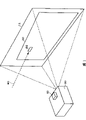
Fig. 1 is the skeleton diagram of image projection situation that an example of present embodiment is shown.
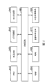
Fig. 2 is the functional block diagram of projector that an example of present embodiment is shown.
Fig. 3 is the hardware block diagram of projector that an example of present embodiment is shown.
Fig. 4 is the process flow diagram of flow process of Flame Image Process that an example of present embodiment is shown.
Fig. 5 is the mode chart of correcting image that an example of present embodiment is shown, and Fig. 5 (A) is the mode chart of the 1st correcting image, and Fig. 5 (B) is the mode chart of the 3rd correcting image.
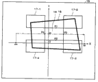
Fig. 6 is the mode chart that is illustrated in the search method in the 1st stage when the central reference position of an example that detects present embodiment.
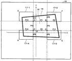
Fig. 7 is the mode chart that is illustrated in the search method in the 2nd stage when the central reference position of an example that detects present embodiment.
Fig. 8 is the mode chart that is illustrated in the search method in the 1st stage when the peripheral reference position of an example that detects present embodiment.
Fig. 9 is the mode chart that is illustrated in the search method in the 2nd stage when the peripheral reference position of an example that detects present embodiment.
Figure 10 is the mode chart that is illustrated in the search method in the 3rd stage when the peripheral reference position of an example that detects present embodiment.
Figure 11 is the mode chart of establishing method of near linear that an example of present embodiment is shown.
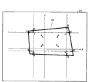
Figure 12 is the mode chart that is illustrated in the search method when the projection objects zone of an example that detects present embodiment.
Embodiment
Occasion with the projector that applies the present invention to have image processing system is that example describes with reference to the accompanying drawings.In addition, embodiment shown below is not any qualification to the summary of the invention of being narrated in the scope of technical scheme.And, be not the formation that illustrates in the following embodiments be that the solution of the invention narrated in the scope as technical scheme is necessary all.
(explanation of total system)
Fig. 1 is the skeleton diagram of image projection situation that an example of present embodiment is shown.
In addition, projector 20 has sensor 60 as taking the unit.Sensor 60 generates photographing information by taking to take in the face of the screen 10 of Display projector image 12.Projector 20 according to photographing information, grasps the position relation of screen 10 and projected image 12 and the shape of projected image 12, carries out the distortion of projected image 12 and the adjustment of display position.
In addition, projector 20, by carrying out and always different Flame Image Process, with the shorter time and correctly generate and the shooting area of sensor 60 in projection objects zone (zone suitable) with screen 10 and the positional information of view field (zone suitable) with projected image 12.
Functional block to the projector 20 that is used for installing this function is illustrated below.
Fig. 2 is the functional block diagram of projector 20 that an example of present embodiment is shown.
The formation of projector 20 comprises the input signal processing unit 110 that the analog rgb signal (R1, G1, B1) from PC (personal computer) etc. is transformed to digital rgb signal (R2, G2, B2); The look converter unit 120 that this digital rgb signal (R2, G2, B2) is transformed to digital rgb signal (R3, G3, B3) for the look and the brightness of correcting image; This digital rgb signal (R3, G3, B3) is transformed to the output signal processing unit 130 of analog rgb signal (R4, G4, B4); And the projecting cell 190 that image is carried out projection according to this analog rgb signal.
In addition, the formation of projecting cell 190 comprises spatial light modulator 192; Drive the driver element 194 of spatial light modulator 192; Light source 196; And lens 198.Driver element 194 according to the picture signal from output signal processing unit 130, drives spatial light modulator 192.So projecting cell 190 will carry out projection through spatial light modulator 192 and lens 198 from the light of light source 196.
In addition, the formation of projector 20 comprises the control information generation unit 114 that generates the control information be used for showing the 1st, the 2nd and the 3rd correcting image; Generate the sensor 60 of the photographing information of correcting image; And interim storage is from the storage unit 140 of the photographing information of sensor 60 etc.
In addition, the formation of projector 20 comprises generation as the 1st difference image of the difference of the 1st and the 2nd photographic images with as the difference image generating unit 160 of the 2nd difference image of the difference of the 1st and the 3rd photographic images, and the outer influence of light of carrying out the processing of the influence of removing outer light is removed unit 170.
In addition, the formation of projector 20 comprises the view field's detecting unit 150 according to the position of the view field in the shooting face (shooting area) of photographing information detecting sensor 60.In addition, the formation of view field's detecting unit 150 comprises the central reference position detection unit 154 that detects a plurality of central reference position that is included in the central block zone in the difference image; Detection is included in the peripheral reference position detecting unit 156 of a plurality of peripheral reference positions in the peripheral piece zone in the difference image; And the view field's information generating unit 158 that generates view field's information of the position of representing view field according to each reference position.
In addition, projector 20 comprises the regional detecting unit 180 of projection objects that generates the projection objects area information relevant with the position in projection objects zone of screen 10 in the shooting area that is equivalent to sensor 60.In addition, the formation of projection objects zone detecting unit 180 comprises range of search decision unit 182; Edge detection unit 184; The check point evaluation unit 188 of evaluation edge check point; And the projection objects area information generation unit 186 that when temporary detecting projection objects zone generates temporary detecting information, generates the projection objects area information.
In addition, projector 20 has the image distortion correction unit of the distortion of correcting orthographic projection image 12.More specifically, projector 20 has image distortion correction amount arithmetic element of the image distortion correction amount being calculated according to view field's information and projection objects area information 162 and the image distortion correction unit of picture signal being proofreaied and correct according to this image distortion correction amount 112.
In addition, as the hardware of the function of each unit that is used for installing above-mentioned projector 20, such as, can use with lower unit.
Fig. 3 is the hardware block diagram of projector 20 that an example of present embodiment is shown.
Such as, as input signal processing unit 110, such as, installations such as A/D transducer 930, image processing circuit 970 can be utilized; As storage unit 140, such as, installations such as RAM950 can be utilized; Remove unit 170, projection objects zone detecting unit 180 as view field's detecting unit 150, difference image generation unit 160, outer influence of light, such as, image processing circuit 970 installations such as grade can be utilized; As image distortion correction amount arithmetic element 162, such as, installations such as CPU910 can be utilized; As control information generation unit 114, such as, installations such as image processing circuit 970, RAM950 can be utilized; As output signal processing unit 130, such as, 940 installations such as grade of D/A transducer can be utilized; As spatial light modulator 192, such as, liquid crystal panel 920 installations such as grade can be utilized; As driver element 194, such as, can utilize storage to be used for driving the installations such as ROM960 of driver of the liquid crystal light valve of liquid crystal panel 920.
In addition, these unit can be through system bus 980 mutual exchange messages between each.
In addition, these each ones both can use hardware to install as circuit, also can use software, as driver, installed.
In addition, also can from storage be used for making computing machine be used as projection objects area information generation unit 186 grades program 900 fetch programs of information storage medium and the function of projection objects area information generation unit 186 grades is installed computing machine.
As this information storage medium 900, such as, can use CD-ROM, DVD-ROM, ROM, RAM, HDD etc., the mode that reads of its program both can be the way of contact, also can be the non-way of contact.
In addition, above-mentioned each function also can be used to install above-mentioned each functional programs and waits to install and replace information storage medium 900 by downloading through transmission path from host apparatus etc.
Utilize these each unit that Flame Image Process is illustrated below.
Fig. 4 is the process flow diagram of flow process of Flame Image Process that an example of present embodiment is shown.In addition, Fig. 5 is the mode chart of correcting image that an example of present embodiment is shown, and Fig. 5 (A) is the mode chart of the 1st correcting image, and Fig. 5 (B) is the mode chart of the 3rd correcting image.
At first, the user is set to projector 20 towards screen 10, connects the power supply of projector 20.
At first, projector 20 carries out projection (step S1) with the complete white image shown in Fig. 5 (A) (entire image is white) 13 as the 1st correcting image.More specifically, control information generation unit 114, the control information of complete white image 13 usefulness of generation (such as, rgb signal etc.), projecting cell 190 is according to the complete white image 13 of this control information projection.
The user confirms whether the central block zone enters in the frame of screen 10, and the position etc. of adjusting projector 20 when not entering starts projector 20 and the processing of execution in step S1~S3 once more once more so that it enters.
Enter in the central block zone under the state of sash of screen 10, the exposure the when graph image 14 on 60 pairs of screens 10 of sensor is taken with complete white image 13 is taken and is generated the 3rd photographing information (step S4).Storage unit 140 storages the 3rd photographing information.
In addition, projector 20 carries out projection (step S5) with all black picture (entire image is a black) as the 2nd correcting image.
Then, difference image generation unit 160 generates as with represented the 1st photographic images of the 1st photographing information with the black and white difference image (step S7) of the 1st difference image of the 2nd represented photographic images of the 2nd photographing information.Storage unit 140 storage black and white difference images.
In addition, difference image generation unit 160 generates as the 1st photographic images with the figure difference image (step S8) of the 2nd difference image of the 3rd represented photographic images of the 3rd photographing information.Storage unit 140 graphics difference images.
In addition, outer influence of light is removed unit 170, whether judgement exists in the 2nd photographing information has high brightness value (more than or equal to predetermined value (such as, 200 etc.) pixel region target luminance value), when having this pixel region, just carry out with the brightness value of this pixel region in the black and white difference image (such as, 50 etc.) be replaced near this pixel region in the black and white difference image brightness value (such as, 30 etc.) processing (step S9).
Can remove the influence of the outer light 80 in the black and white difference image by such processing.
In addition, view field's detecting unit 150 according to the figure difference image, detects the view field (step S10) in the shooting area.More specifically, view field's detecting unit 150 detects a plurality of (being 4 in the present embodiment) the central reference position in the central block zone be included in the figure difference image and is included in a plurality of (being 8 in the present embodiment) peripheral reference position in the peripheral piece zone in the figure difference image.
Fig. 6 is the mode chart that is illustrated in the search method in the 1st stage when the central reference position of an example that detects present embodiment.In addition, Fig. 7 is the mode chart that is illustrated in the search method in the 2nd stage when the central reference position of an example that detects present embodiment.
Central reference position detection unit 154, in order to detect the position in view field in the shooting area 15 suitable (zone suitable) with projected image 12 with shooting face, at first, 4 central reference positions of test pattern image.In addition, for the purpose of making the explanation easy to understand, the projection objects of in each figure, drawing zone 18, but the occasion of a part of the peripheral piece zone 17-1~17-4 of the outside that does not comprise projection objects zone 18 and projection objects zone 18 is also arranged in the difference image of reality.
More specifically, central reference position detection unit 154 is for difference image, as shown in Figure 6, play y=ym only to each pixel retrieval difference value by going up along imagination central block zone 16 residing lengthwise position x=xc, differentiate some P1, P2 that difference value changes from y=yp.Such as, suppose be P1 (xc, y1), P2 (xc, some y2).
In addition, the value of the retrieval reference position of xc, yp, ym etc., such as, both can also can determine by experiment by the field angle separately and the determining positions of lens 198 and sensor 60, perhaps also can determine corresponding to shooting results.For described later other the retrieval reference position too.
Subsequently, central reference position detection unit 154 as shown in Figure 7, upward plays x=xp from x=xm along the lateral attitude y=yc that with P1, P2 is benchmark and ends each pixel retrieval difference value, differentiates some P3, P4 that difference value changes thus.In addition, herein, such as, yc=(y1+y2)/2.
Like this, central reference position detection unit 154, with 4 central reference position P1 in expression central block zone 16 (xc, y1), P2 (xc, y2), P3 (x1, yc), (x2, central reference positional information yc) outputs to peripheral reference position detecting unit 156 to P4.
Periphery reference position detecting unit 156, according to the central reference positional information, 8 peripheral reference positions of test pattern image.
Fig. 8 is the mode chart that is illustrated in the search method in the 1st stage when the peripheral reference position of an example that detects present embodiment.In addition, Fig. 9 is the mode chart that is illustrated in the search method in the 2nd stage when the peripheral reference position of an example that detects present embodiment.In addition, Figure 10 is the mode chart that is illustrated in the search method in the 3rd stage when the peripheral reference position of an example that detects present embodiment.
The edge detection unit 184 of projection objects zone detecting unit 180, central reference position P1~P4 according to central block zone 16, laterally along each the retrieval boost line that is positioned at central block zone 16, as searching object each pixel is carried out rim detection from the Y coordinate points y1 separately of P1 and P2 and y2 with the black and white difference image for the predetermined ratio inboard of lateral length from P3, P4.As a result, can detect 4 rim detection point ZUVW.
In addition, as the method for edge detection process, such as, can adopt the color filter that utilizes a plurality of pixels to detect the method at edge and do not utilize color filter and detect brightness value as the method at the edge of each pixel etc.
Then, peripheral reference position detecting unit 156, the value that calculating will be put the predetermined ratio of the distance (difference value) between the Y coordinate figure y1 of smaller value and P1 among the Y coordinate figure yU of the Y coordinate figure yZ of Z and some U is added to resulting value yP on the y1.In addition, peripheral reference position detecting unit 156, the value that calculating will be put the predetermined ratio of higher value among the Y coordinate figure yW of the Y coordinate figure yV of V and some W and the distance between the Y coordinate figure y2 of P2 deducts the value yQ of gained from y2.
In addition, peripheral reference position detecting unit 156 calculates that to be positioned at from the X coordinate figure xZ of a Z and some W be the X coordinate figure xR of position of predetermined ratio inboard of the lateral length in central block zone 16.In addition, peripheral reference position detecting unit 156 calculates that to be positioned at from the X coordinate figure xU of a U and some V be the X coordinate figure xS of position of predetermined ratio inboard of the lateral length in central block zone 16.
Subsequently, peripheral reference position detecting unit 156 outputs to view field's information generating unit 158 with peripheral reference position information and the central reference positional information of representing the coordinate of these 8 points.
View field's information generating unit 158 according to peripheral reference position information and central reference positional information, utilizes near linear (curve of approximation also can) to detect four jiaos position of view field.
Figure 11 is the mode chart of establishing method of near linear that an example of present embodiment is shown.
View field's information generating unit 158 according to the coordinate of a P5, some P3 and some P6, is set the near linear of representing with the dotted line of Figure 10.Profit uses the same method, and view field's information generating unit 158 as shown in figure 11, is set 4 near linears being represented by dotted lines, differentiate each near linear 4 intersection point A (xA, yA)~(xD yD) is four jiaos the point in central block zone 16 to D.
Utilize above method, view field's information generating unit 158, view field's information of four jiaos some EFGH of the view field that expression projected image 12 is suitable outputs to image distortion correction amount arithmetic element 162.
In addition, projection objects zone detecting unit 180 according to the black and white difference image, detects the projection objects zone 18 (step S11) in the shooting area 15.Below, the position probing in projection objects zone 18 handled being illustrated.
Figure 12 is the mode chart that is illustrated in the search method when the projection objects zone of an example that detects present embodiment.
At first, range of search decision unit 182 is a decision rim detection object, according to the coordinate information of four jiaos of ABCD in black and white difference image and above-mentioned central block zone 16, sets by than regional ABCD four retrieval boost lines a little in the outer part.More specifically, boost line as object, retrieved in the coordinate p% place setting in the outer part of four jiaos of ABCD in the central block zone 16 that Billy is detected with central reference position detection unit 154 with the black and white difference image in range of search decision unit 182.
Such as, the 1st retrieval boost line y=round[max (yA, yB)+(yA-yD) * p/100], the 2nd retrieval boost line x=round[max (xB, xC)+(xB-xA) * p/100], the 3rd retrieval boost line y=round[min (yC, yD)-(yA-yD) * p/100], the 4th retrieval boost line x=round[min (xA, xD)-(xB-xA) * p/100].In addition, wherein, max, min, round are respectively the functions that returns peaked function among the independent variable, returns the function of minimum value among the independent variable and return value with the 1st of the radix point of independent variable the integer after rounding up.
Like this, by setting 4 retrieval boost lines, as shown in figure 12, determine 4 intersection I JKL of 4 retrieval boost lines.In addition, as mentioned above, also can not set 4 retrieval boost lines, but will utilize Y=yP, Y=yQ that peripheral reference position detecting unit calculates and be set at 4 and retrieve boost lines differentiating (corresponding) two straight lines parallel of calculating when P9~P12 with Y-axis with Y=yP, Y=yQ, with its intersection point as IJKL.
And then, edge detection unit 184, respectively from line segment TO the boundary line direction towards projection objects zone 18, from line segment NQ the boundary line direction towards projection objects zone 18, from line segment PS the boundary line direction towards projection objects zone 18, from line segment RM the boundary line direction towards projection objects zone 18 each pixel is carried out rim detection.
Adopting the occasion of carrying out rim detection along the boundary line direction towards projection objects zone 18 from line segment TO herein is that example describes.Edge detection unit 184 is carried out the scope of rim detection in line segment TO, such as, be and direction parallel with Y-axis, in line segment IJ, set 7, two retrieval lines respectively are set respectively in line segment TI, JO.In addition, side search domain during the zone of 7 retrieval lines of this setting is called is called outside search domain with each two zone setting two retrieval lines.
So edge detection unit 184 by on these retrieval lines each pixel being carried out rim detection, can detect maximum 11 rim detection points on straight line MN, but can detect maximum 13 rim detection points when comprising a some MN.Edge detection unit 184 is carried out similar detection to other line segment NQ, line segment PS, line segment RM.
In addition, edge detection unit 184, the point of rim detection point to the each point of MN, OP, QR, ST among a side point in shooting area 15, detect less than occasion, just be judged as be used for retrieving detection less than the outside search domain of point do not have the boundary line in projection objects zone 18, in this zone, do not carry out the setting and the rim detection of retrieval line.In addition, edge detection unit 184, the point of rim detection point to the right both sides' of the each point of MN, OP, QR, ST point in shooting area 15, all detect less than occasion, just judge for detect less than the parallel direction of line segment on do not have the boundary line in close projection objects zone 18, be used for retrieving detection less than the middle side search domain of line segment and outside search domain in do not carry out the setting and the rim detection of retrieval line.
By carrying out these processing, edge detection unit 184 can be omitted rim detection in low zone to the possibility that has projection objects zone 18, just can carry out processing more at high speed.
Projection objects area information generation unit 186, according to by edge detection unit 184 detected a plurality of rim detection points, but by setting linear-apporximation straight line or linear-apporximation curve offhand decision projection objects zone 18.
Then, check point evaluation unit 188, among by edge detection unit 184 detected a plurality of rim detection points, whether each rim detection point is estimated more than or equal to predetermined value by judging with the linear-apporximation straight line or the departing from of linear-apporximation curve that set by projection objects area information generation unit 186.
Like this, projection objects area information generation unit 186 only uses not the rim detection point got rid of from process object just can detect projection objects zone 18 with high precision more.
More specifically, edge detection unit 184 according to the black and white difference image, is carried out rim detection to the neighboring pixel of the rim detection point do not got rid of from process object.Then, edge detection unit 184 outputs to projection objects area information generation unit 186 with edge detecting information.
Projection objects area information generation unit 186 is according to this edge detecting information, by setting linear-apporximation straight line or linear-apporximation curve once more, decision projection objects zone 18.Then, projection objects area information generation unit 186 generates the projection objects area information of four jiaos position representing projection objects zone 18 and outputs to image distortion correction amount arithmetic element 162.
Subsequently, ground projected image (step S12) according to view field's information and projection objects area information, is proofreaied and correct to the distortion of projected image 12 by projector 20.
More specifically, image distortion correction amount arithmetic element 162, according to from view field's information of view field's information generating unit 158 and from the projection objects area information of projection objects area information generation unit 186, grasp the position relation and the shape of screen 10 and projected image 12, the distortion of correcting orthographic projection image 12, computed image distortion correction amount is so that projected image 12 becomes desired asperratio (aspect ratio).
Then, image distortion correction unit 112, according to this image distortion correction amount, (R1, G1, B1) proofreaies and correct to picture signal.As a result, projector 20 can will not have the image of distortion to carry out projection with the shape that keeps desired aspect ratio.
Certainly, the aberration emendation method of image is not limited thereto.Such as, projector 20, the brightness value that also can detect photographic images is for maximum pixel, according to the distortion of this locations of pixels correcting image.
As mentioned above, according to present embodiment, projector 20 is used for removing the processing of outer influence of light by execution, can detect the projection objects zone 18 in the photographic images rightly under the state of the influence of removing the outer light 80 that produces sharp contrast.
In addition, according to present embodiment, projection objects zone 18 etc. is detected by the difference image of removing outer influence of light being carried out rim detection etc. by projector 20, can be with high Precision Detection projection objects zone 18 more etc.
In addition, according to present embodiment, projector 20, by after temporary detecting projection objects zone 18 near its boundary line detection projection objects zone 18, can and correctly generate the positional information in projection objects zone 18 in the shorter time.As a result, projector 20 can reduce the calculation process amount of entire image processing system, can carry out high speed image with low load and handle.
In addition, according to present embodiment, projector 20 by carry out rim detection under the state that further narrows the zone that becomes the rim detection object, can generate the positional information in projection objects zone 18 in the shorter time.
In addition, projector 20 by carrying out the processing except the rim detection point that will depart from from the linear-apporximation straight line, can reduce the influence of noise etc., can more correctly generate the positional information in projection objects zone 18.
As a result, projector 20 can carry out the distortion correction of projected image 12 rightly.
In addition, projector 20 shown in the graph image 14 that Fig. 5 (B) illustrates, is not only the image that central authorities and its periphery also have feature by use, just compare with using in the occasion of the characteristic graph image of centre, can be with four jiaos of high precision differentiation view field more.
Such as, the point that near its brightness value changes when the some P1, the some P2 that differentiate as shown in Figure 6, also can be differentiated by projector 20.Yet, adopting these narrow at interval a plurality of points to set the occasion of near linears, with adopt between a plurality of points of keeping apart occasion of setting near linears compare, bigger in the influence of the error pairing approximation straight line of a pixel of the some part that constitutes near linear.
In the present embodiment, projector 20, by the reference point in use central block zone 16 and the reference point of peripheral piece zone 17-1~17-4, owing to can utilize a plurality of points of devices spaced apart to set near linears, so can be with four jiaos of higher precision discrimination view field.
In addition, the result, projector 20 can avoid the influence of the shading of projector 20 or sensor 60, the position of can the precision highland grasping whole view field.
In addition, by using graph image 14, view field even exceed screen 10 at the peripheral part of projected image 12, also can be detected rightly by projector 20.
In addition, according to present embodiment, projector 20 is only retrieved zone necessary in the difference image by whole difference image not being retrieved, can be simpler and easy and detect the position of view field at high speed.
In addition, when correcting image is carried out projection, by temporary transient setting automatic exposure complete white image is taken and to be generated the 1st photographing information, can generate the 1st photographing information with the exposure that is fit to environment for use.In addition, projector 20, the exposure by with complete white image taking the time generates the 2nd and the 3rd photographing information, can generate the 2nd and the 3rd photographing information to be applicable to the exposure that difference image generates.
Particularly, by take complete white image with automatic exposure setting, sensor 60, the occasion of the influence of light 80 outside screen 10 is subjected to, the reflected light that the reflectivity of, screen 10 far away excessively at projector distance is low excessively to make projected light excessively a little less than, or among the strong excessively any occasion of the too high reflected light that makes projected light of reflectivity near excessively at projector distance, screen 10, compare with the occasion of taking with fixing exposure, can effectively utilize the dynamic range of sensor 60 and take.
(variation)
More than be illustrated using preferred implementation of the present invention, but application of the present invention is not limited to the foregoing description.
Such as, in the above-described embodiments, outer influence of light is removed unit 170, in the 1st or the 2nd photographing information, there is the occasion have more than or equal to the pixel region of the brightness value of predetermined value, execution is replaced into the brightness value of this pixel region in the black and white difference image near the processing of the brightness value this pixel region in the black and white difference image, but as this variation, also can not carry out edge detection process and set particular value (such as, 300 etc.) as the brightness value of this pixel region of black and white difference image or figure difference image.
Then, edge detection unit 184, detecting the occasion of this particular value, edge detection results at this part is carried out invalidation, central reference position detection unit 154 and peripheral reference position detecting unit 156, detecting the occasion of this particular value, execution is not differentiated this part as central reference position and peripheral reference position processing.
In addition, projection objects zone detecting unit 180 and view field's detecting unit 150, in the detected object zone, comprise have more than or equal to predetermined value (such as, be speculated as the minimum value that is subjected to outer influence of light etc.) the occasion of pixel region of brightness value, also can carry out and ignore this pixel region, make it invalid or get rid of and detect processing.
In addition, in the above-described embodiments, sensor 60 is to use all black picture to generate the 2nd photographing information, but as variation, and the screen 10 in the time of also can be to non-projection is taken and generated the 2nd photographing information.
In addition, outer influence of light is removed unit 170, also the figure difference image can be carried out the processing that outer influence of light is removed as object.
In addition, difference image generation unit 160, the difference image that also can use all black picture and graph image 14 is as the figure difference image.
In addition, projecting cell 190 also can be under the state of received image signal not, from light source 196 under the state of the planar light of screen 10 projections, by the shooting of sensor 60, generate the 1st or the 2nd photographing information.In other words, projector 20 not necessarily must carry out the projection of complete white image 13 or all black picture.
In addition, the position of projected image 12 and screen 10 relation is not limited to example shown in Figure 1.Such as, the whole housing of projected image 12 both can be in the outside of the housing of screen 10, also can be side within it.
In addition, projector 20, except the distortion of correcting image, also can utilize view field's information and projection objects area information carry out projected image 12 the position adjustment, detect the indicating positions in projected image 12, utilize laser designator etc. etc. or utilize the projection objects area information to carry out that the look of projected image 12 is uneven to be proofreaied and correct etc.
In addition, such as, sorted order can be any, projector 20, also can difference image is retrieved along transverse direction detecting central reference position or peripheral reference position after, based on this central reference position or should the periphery reference position at the enterprising line retrieval of longitudinal direction.
In addition, view field also can be detected by projector 20 after detecting projection objects zone 18.
In addition, the shape of central block zone 16 and peripheral piece zone 17-1~17-4 is not limited to rectangle, such as, also can adopt rectangle shapes in addition such as circle.Certainly, the shape in the shape of whole correcting image and central block zone 16 is not limited to similar figures, is that corresponding shape gets final product so long as can recognize both.In addition, the number of peripheral piece zone 17-1~17-4 also is arbitrarily.
In addition, complete white image 13, all black picture, the projection of graph image 14 and the order of shooting are arbitrarily.Such as, projector 20, both can be at first after with graph image 14 projections the user confirm the processing of execution in step S1~S6 after whether the central block zone enters in the screen 10, also can be after the projection all black picture be taken, projecting figure image 14 is taken.
In addition, in the occasion to projection objects thing projected images such as the blackboard beyond the screen 10, blanks, the present invention also is effective.
In addition, such as, in the above-described embodiments, be to be that example describes, but also can be installed to projector 20 image display device in addition that the CRT (cathode-ray tube (CRT)) beyond the projector 20 waits with the occasion that image processing system is installed to projector 20.In addition, as projector 20, except liquid crystal projector, also can use projector that utilizes DMD (Digital Micromirror Device) for example etc.In addition, DMD is the trade mark of Texas ,Usa instrument company.
In addition, the function of above-mentioned projector 20, such as, both can be to be installed on the single projector, also can disperse to be installed on a plurality for the treatment of apparatus (such as, by projector and PC dispersion treatment).
In addition, in the above-described embodiments, be that sensor 60 is built in the structure in the projector 20, but also can be that sensor 60 and projector 20 are the structure of mutual independent device.
Claims (10)
1. image processing system is characterized in that comprising:
With the 1st correcting image or planar light and the 2nd correcting image or planar light projecting cell to the projection of projection objects thing;
There is the above-mentioned projection objects thing of above-mentioned the 1st correcting image or planar light to take to projection and generates the 1st photographing information, and have the above-mentioned projection objects thing of above-mentioned the 2nd correcting image or planar light to take to projection and generate the shooting unit of the 2nd photographing information;
Generation is by represented the 1st photographic images of above-mentioned the 1st photographing information with by the difference image generation unit of the 1st difference image of the 2nd represented photographic images of above-mentioned the 2nd photographing information;
When in the above-mentioned the 1st or the 2nd photographing information, having the pixel region have more than or equal to the target luminance value of predetermined value, carry out will this pixel region in above-mentioned the 1st difference image the target luminance value outer influence of light of processing that is replaced near the processing of the target luminance value of this pixel region in above-mentioned the 1st difference image or particular value is set at the target luminance value of this pixel region in above-mentioned the 1st difference image remove the unit; And
According to the 1st difference image that utilizes after above-mentioned outer influence of light is removed cell processing, carry out edge detection process, generate the projection objects zone detecting unit of the projection objects area information relevant thus with the position in projection objects zone of above-mentioned projection objects thing in the shooting area that is equivalent to above-mentioned shooting unit
Above-mentioned projection objects zone detecting unit when detecting above-mentioned particular value regional when existing in above-mentioned edge detection process, carries out making the invalid processing of this regional edge detection results.
2. image processing system is characterized in that comprising:
With the 1st correcting image or planar light projecting cell to the projection of projection objects thing;
Projection is had the above-mentioned projection objects thing of above-mentioned the 1st correcting image or planar light to take and generates the 1st photographing information, and the above-mentioned projection objects thing during to non-projection is taken and generated the shooting unit of the 2nd photographing information;
Generation is by represented the 1st photographic images of above-mentioned the 1st photographing information with by the difference image generation unit of the 1st difference image of the 2nd represented photographic images of above-mentioned the 2nd photographing information;
When in the above-mentioned the 1st or the 2nd photographing information, having the pixel region have more than or equal to the target luminance value of predetermined value, carry out will this pixel region in above-mentioned the 1st difference image the target luminance value outer influence of light of processing that is replaced near the processing of the target luminance value of this pixel region in above-mentioned the 1st difference image or particular value is set at the target luminance value of this pixel region in above-mentioned the 1st difference image remove the unit; And
According to the 1st difference image that utilizes after above-mentioned outer influence of light is removed cell processing, carry out edge detection process, generate the projection objects zone detecting unit of the projection objects area information relevant thus with the position in projection objects zone of above-mentioned projection objects thing in the shooting area that is equivalent to above-mentioned shooting unit
Above-mentioned projection objects zone detecting unit when detecting above-mentioned particular value regional when existing in above-mentioned edge detection process, carries out making the invalid processing of this regional edge detection results.
3. image processing system as claimed in claim 1 is characterized in that:
The view field's detecting unit that possesses the relevant view field's information in the position of the view field in the shooting area that generates with above-mentioned shooting unit;
Above-mentioned projecting cell, with the 3rd correcting image to the projection of above-mentioned projection objects thing;
Above-mentioned shooting unit has the above-mentioned projection objects thing of above-mentioned the 3rd correcting image to take to projection and generates the 3rd photographing information;
Above-mentioned difference image generation unit generates above-mentioned the 1st photographic images and by the 2nd difference image of the 3rd represented photographic images of above-mentioned the 3rd photographing information;
Above-mentioned the 2nd difference image is made of near the central block zone the central authorities that are positioned at this difference image, the peripheral piece zone of periphery that is positioned at this central block zone and the background area beyond above-mentioned central block zone and the above-mentioned peripheral piece zone;
Each pixel in above-mentioned central block zone and the above-mentioned peripheral piece zone has different target luminance values with each pixel in the above-mentioned background zone;
Above-mentioned view field detecting unit comprises:
According to above-mentioned the 2nd difference image, detect the central reference position detection unit of a plurality of central reference position in the above-mentioned central block zone in the shooting area of above-mentioned shooting unit;
According to above-mentioned central reference position, detect the peripheral reference position detecting unit of a plurality of peripheral reference positions in the above-mentioned peripheral piece zone in the above-mentioned shooting area; And
According to above-mentioned central reference position and above-mentioned peripheral reference position, generate view field's information generating unit of above-mentioned view field information.
4. image processing system as claimed in claim 3 is characterized in that:
Comprise according to above-mentioned projection objects area information and above-mentioned view field information the image distortion correction unit that the distortion of image is proofreaied and correct;
Above-mentioned projecting cell, with the image that utilizes above-mentioned image distortion correction unit to be proofreaied and correct to the projection of above-mentioned projection objects thing.
5. as any one the described image processing system in the claim 1~4, it is characterized in that: above-mentioned shooting unit, generate above-mentioned the 1st photographing information by utilizing automatic exposure to take, generate above-mentioned the 2nd photographing information by taking with the exposure that this automatic exposure was determined.
6. projector is characterized in that comprising:
With the 1st correcting image or planar light and the 2nd correcting image or planar light projecting cell to the projection of projection objects thing;
There is the above-mentioned projection objects thing of above-mentioned the 1st correcting image or planar light to take to projection and generates the 1st photographing information, and have the above-mentioned projection objects thing of above-mentioned the 2nd correcting image or planar light to take to projection and generate the shooting unit of the 2nd photographing information;
Generation is by represented the 1st photographic images of above-mentioned the 1st photographing information with by the difference image generation unit of the 1st difference image of the 2nd represented photographic images of above-mentioned the 2nd photographing information;
When in the above-mentioned the 1st or the 2nd photographing information, having the pixel region have more than or equal to the target luminance value of predetermined value, carry out will this pixel region in above-mentioned the 1st difference image the target luminance value outer influence of light of processing that is replaced near the processing of the target luminance value of this pixel region in above-mentioned the 1st difference image or particular value is set at the target luminance value of this pixel region in above-mentioned the 1st difference image remove the unit; And
According to the 1st difference image that utilizes after above-mentioned outer influence of light is removed cell processing, carry out edge detection process, generate the projection objects zone detecting unit of the projection objects area information relevant thus with the position in projection objects zone of above-mentioned projection objects thing in the shooting area that is equivalent to above-mentioned shooting unit
Above-mentioned projection objects zone detecting unit when detecting above-mentioned particular value regional when existing in above-mentioned edge detection process, carries out making the invalid processing of this regional edge detection results.
7. image processing method is characterized in that:
With the 1st correcting image or planar light to the projection of projection objects thing;
There is the above-mentioned projection objects thing of above-mentioned the 1st correcting image or planar light to take to projection and generates the 1st photographing information;
With the 2nd correcting image or planar light to the projection of above-mentioned projection objects thing;
There is the above-mentioned projection objects thing of above-mentioned the 2nd correcting image or planar light to take to projection and generates the 2nd photographing information;
Generation is by represented the 1st photographic images of above-mentioned the 1st photographing information with by the 1st difference image of the 2nd represented photographic images of above-mentioned the 2nd photographing information;
When in the above-mentioned the 1st or the 2nd photographing information, having the pixel region have more than or equal to the target luminance value of predetermined value, carry out will this pixel region in above-mentioned the 1st difference image target luminance value be replaced near the processing of the target luminance value of this pixel region in above-mentioned the 1st difference image or particular value be set at the processing of the target luminance value of this pixel region in above-mentioned the 1st difference image;
The 1st difference image after handling according to this carries out edge detection process, generate thus with the shooting area that is equivalent to above-mentioned shooting unit in the relevant projection objects area information in position in projection objects zone of above-mentioned projection objects thing,
When existing in above-mentioned edge detection process, detecting above-mentioned particular value regional, carry out making the invalid processing of this regional edge detection results.
8. image processing method as claimed in claim 7 is characterized in that:
With the 3rd correcting image to the projection of above-mentioned projection objects thing;
There is the above-mentioned projection objects thing of above-mentioned the 3rd correcting image to take to projection and generates the 3rd photographing information;
Generate above-mentioned the 1st photographic images and by the 2nd difference image of the 3rd represented photographic images of above-mentioned the 3rd photographing information;
Above-mentioned the 2nd difference image is made of near the central block zone the central authorities that are positioned at this difference image, the peripheral piece zone of periphery that is positioned at this central block zone and the background area beyond above-mentioned central block zone and the above-mentioned peripheral piece zone;
Each pixel in above-mentioned central block zone and the above-mentioned peripheral piece zone has different target luminance values with each pixel in the above-mentioned background zone;
According to above-mentioned the 2nd difference image, detect a plurality of central reference position in the above-mentioned central block zone in the shooting area;
According to above-mentioned central reference position, detect a plurality of peripheral reference position in the above-mentioned peripheral piece zone in the above-mentioned shooting area;
According to above-mentioned central reference position and above-mentioned peripheral reference position, generate and the relevant view field's information in view field position in the above-mentioned shooting area.
9. image processing method as claimed in claim 8 is characterized in that:
According to above-mentioned projection objects area information and above-mentioned view field information, the distortion of image is proofreaied and correct;
With the image proofreaied and correct to the projection of above-mentioned projection objects thing.
10. as any one the described image processing method in the claim 7~9, it is characterized in that: generate above-mentioned the 1st photographing information by taking, generate above-mentioned the 2nd photographing information by taking with the exposure that this automatic exposure was determined with automatic exposure.
Applications Claiming Priority (2)
| Application Number | Priority Date | Filing Date | Title |
|---|---|---|---|
| JP156273/2004 | 2004-05-26 | ||
| JP2004156273A JP3888465B2 (en) | 2004-05-26 | 2004-05-26 | Image processing system, projector, and image processing method |
Publications (2)
| Publication Number | Publication Date |
|---|---|
| CN1702542A CN1702542A (en) | 2005-11-30 |
| CN100426126C true CN100426126C (en) | 2008-10-15 |
Family
ID=34936966
Family Applications (1)
| Application Number | Title | Priority Date | Filing Date |
|---|---|---|---|
| CNB2005100723209A Expired - Fee Related CN100426126C (en) | 2004-05-26 | 2005-05-26 | Image processing system, projector and image processing method |
Country Status (6)
| Country | Link |
|---|---|
| US (1) | US7233707B2 (en) |
| EP (1) | EP1601181A1 (en) |
| JP (1) | JP3888465B2 (en) |
| KR (1) | KR100749069B1 (en) |
| CN (1) | CN100426126C (en) |
| TW (1) | TW200602787A (en) |
Families Citing this family (24)
| Publication number | Priority date | Publication date | Assignee | Title |
|---|---|---|---|---|
| JP4150924B2 (en) * | 2003-07-02 | 2008-09-17 | セイコーエプソン株式会社 | Image processing system, projector, program, information storage medium, and image processing method |
| JP4232042B2 (en) | 2005-01-07 | 2009-03-04 | セイコーエプソン株式会社 | Projection control system, projector, program, information storage medium, and projection control method |
| JP4126564B2 (en) | 2005-02-14 | 2008-07-30 | セイコーエプソン株式会社 | Image processing system, projector, program, information storage medium, and image processing method |
| JP4085283B2 (en) | 2005-02-14 | 2008-05-14 | セイコーエプソン株式会社 | Image processing system, projector, program, information storage medium, and image processing method |
| US20070058881A1 (en) * | 2005-09-12 | 2007-03-15 | Nishimura Ken A | Image capture using a fiducial reference pattern |
| TWI353531B (en) * | 2008-05-13 | 2011-12-01 | Wistron Corp | Method and a device of adjusting a color temperatu |
| JP5431312B2 (en) * | 2008-05-21 | 2014-03-05 | パナソニック株式会社 | projector |
| JP4930638B2 (en) * | 2008-05-30 | 2012-05-16 | 富士通株式会社 | Image correction apparatus and image correction method |
| JP5200759B2 (en) * | 2008-08-22 | 2013-06-05 | セイコーエプソン株式会社 | Projection display apparatus and image correction method |
| US8400468B2 (en) * | 2009-08-27 | 2013-03-19 | Seiko Epson Corporation | Projector masks for calibrating projector-based display systems |
| US20110134283A1 (en) * | 2009-12-09 | 2011-06-09 | Samsung Electronics Co., Ltd. | Photographing apparatus and photographing method |
| JP4936091B2 (en) * | 2010-03-31 | 2012-05-23 | カシオ計算機株式会社 | Light source unit and projector |
| CN102314259B (en) * | 2010-07-06 | 2015-01-28 | 株式会社理光 | Method for detecting objects in display area and equipment |
| WO2012024487A2 (en) * | 2010-08-18 | 2012-02-23 | Savannah River Nuclear Solutions, Llc | System and method for the identification of radiation in contaminated rooms |
| CN103379269B (en) * | 2012-04-26 | 2017-11-24 | 富泰华工业(深圳)有限公司 | Camera system, image pickup method and the electronic equipment using the camera system |
| US8836910B2 (en) * | 2012-06-04 | 2014-09-16 | James A. Cashin | Light and sound monitor |
| JP6217100B2 (en) * | 2013-03-22 | 2017-10-25 | セイコーエプソン株式会社 | Image processing apparatus, projector, image processing method, and program |
| CN103905762B (en) * | 2014-04-14 | 2017-04-19 | 上海索广电子有限公司 | Method for automatically detecting projection picture for projection module |
| JP2017092521A (en) * | 2015-11-02 | 2017-05-25 | キヤノン株式会社 | Display device and control method of the same |
| JP6046286B1 (en) * | 2016-01-13 | 2016-12-14 | 東芝エレベータ株式会社 | Image processing device |
| JP6842329B2 (en) * | 2017-03-24 | 2021-03-17 | 株式会社Screenホールディングス | Image processing method and image processing equipment |
| CN109788262A (en) * | 2017-11-15 | 2019-05-21 | 中强光电股份有限公司 | Optical projection system and its image projecting method |
| CN109143829A (en) * | 2018-10-16 | 2019-01-04 | 江苏达伦电子股份有限公司 | Clock projection arrangement and clock project ceiling lamp |
| CN113674303A (en) * | 2021-08-31 | 2021-11-19 | Oppo广东移动通信有限公司 | Image processing method, image processing device, electronic equipment and storage medium |
Citations (6)
| Publication number | Priority date | Publication date | Assignee | Title |
|---|---|---|---|---|
| EP0616473A2 (en) * | 1993-03-17 | 1994-09-21 | Matsushita Electric Industrial Co., Ltd. | Image correction apparatus |
| US20010010514A1 (en) * | 1999-09-07 | 2001-08-02 | Yukinobu Ishino | Position detector and attitude detector |
| JP2001268326A (en) * | 2000-03-23 | 2001-09-28 | Minolta Co Ltd | Image processing apparatus and image pickup device |
| US20030058252A1 (en) * | 2001-09-27 | 2003-03-27 | Seiko Epson Corporation | Image display system, projector, program, information storage medium, and image processing method |
| US20030147053A1 (en) * | 2001-05-31 | 2003-08-07 | Hideki Matsuda | Image display system, projector, information storage medium, and image processing method |
| WO2004001501A1 (en) * | 2002-06-24 | 2003-12-31 | Silverbrook Research Pty Ltd | Photographic prints having magnetically recordable media |
Family Cites Families (10)
| Publication number | Priority date | Publication date | Assignee | Title |
|---|---|---|---|---|
| JPH1141463A (en) * | 1997-07-23 | 1999-02-12 | Minolta Co Ltd | Image reader |
| JP4089051B2 (en) * | 1998-02-18 | 2008-05-21 | セイコーエプソン株式会社 | Image processing apparatus and image processing method |
| AUPP701798A0 (en) * | 1998-11-09 | 1998-12-03 | Silverbrook Research Pty Ltd | Image creation method and apparatus (ART75) |
| JP4434381B2 (en) | 1999-10-12 | 2010-03-17 | キヤノン株式会社 | Coordinate input device |
| JP2002365718A (en) | 2001-06-04 | 2002-12-18 | Hitachi Ltd | Multidisplay device and regulating method for the same |
| JP3894302B2 (en) * | 2002-03-25 | 2007-03-22 | セイコーエプソン株式会社 | Image display system, image processing method, program, and information storage medium |
| JP3719424B2 (en) * | 2002-05-09 | 2005-11-24 | セイコーエプソン株式会社 | Image processing system, projector, image processing method, program, and information storage medium |
| JP3731663B2 (en) * | 2002-12-04 | 2006-01-05 | セイコーエプソン株式会社 | Image processing system, projector, and image processing method |
| JP2004228948A (en) | 2003-01-23 | 2004-08-12 | Seiko Epson Corp | Image processing system, projector, program, information storage medium and image processing method |
| JP3871061B2 (en) * | 2003-03-25 | 2007-01-24 | セイコーエプソン株式会社 | Image processing system, projector, program, information storage medium, and image processing method |
-
2004
- 2004-05-26 JP JP2004156273A patent/JP3888465B2/en not_active Expired - Fee Related
-
2005
- 2005-05-25 KR KR1020050044279A patent/KR100749069B1/en not_active IP Right Cessation
- 2005-05-25 EP EP05011409A patent/EP1601181A1/en not_active Withdrawn
- 2005-05-25 TW TW094117099A patent/TW200602787A/en not_active IP Right Cessation
- 2005-05-26 US US11/137,350 patent/US7233707B2/en not_active Expired - Fee Related
- 2005-05-26 CN CNB2005100723209A patent/CN100426126C/en not_active Expired - Fee Related
Patent Citations (6)
| Publication number | Priority date | Publication date | Assignee | Title |
|---|---|---|---|---|
| EP0616473A2 (en) * | 1993-03-17 | 1994-09-21 | Matsushita Electric Industrial Co., Ltd. | Image correction apparatus |
| US20010010514A1 (en) * | 1999-09-07 | 2001-08-02 | Yukinobu Ishino | Position detector and attitude detector |
| JP2001268326A (en) * | 2000-03-23 | 2001-09-28 | Minolta Co Ltd | Image processing apparatus and image pickup device |
| US20030147053A1 (en) * | 2001-05-31 | 2003-08-07 | Hideki Matsuda | Image display system, projector, information storage medium, and image processing method |
| US20030058252A1 (en) * | 2001-09-27 | 2003-03-27 | Seiko Epson Corporation | Image display system, projector, program, information storage medium, and image processing method |
| WO2004001501A1 (en) * | 2002-06-24 | 2003-12-31 | Silverbrook Research Pty Ltd | Photographic prints having magnetically recordable media |
Also Published As
| Publication number | Publication date |
|---|---|
| JP3888465B2 (en) | 2007-03-07 |
| JP2005341139A (en) | 2005-12-08 |
| CN1702542A (en) | 2005-11-30 |
| KR20060048105A (en) | 2006-05-18 |
| TW200602787A (en) | 2006-01-16 |
| US7233707B2 (en) | 2007-06-19 |
| US20050265713A1 (en) | 2005-12-01 |
| TWI312099B (en) | 2009-07-11 |
| KR100749069B1 (en) | 2007-08-13 |
| EP1601181A1 (en) | 2005-11-30 |
Similar Documents
| Publication | Publication Date | Title |
|---|---|---|
| CN100426126C (en) | Image processing system, projector and image processing method | |
| CN100380945C (en) | Image processing system, projector, image processing method | |
| CN100435551C (en) | Image processing system, projector, and image processing method | |
| JP4055010B2 (en) | Image processing system, projector, program, information storage medium, and image processing method | |
| US6932480B2 (en) | Image processing system, projector, program, information storage medium and image processing method | |
| JP3871061B2 (en) | Image processing system, projector, program, information storage medium, and image processing method | |
| CN100547478C (en) | Projector and method for controlling projection | |
| US8322862B2 (en) | Projector, computer program product, and trapezoidal distortion correcting method | |
| US8011789B2 (en) | Rear projection display | |
| US20110032381A1 (en) | Projector, computer program product, and exposure adjusting method | |
| CN101091137A (en) | Method of and apparatus for adjusting pose of a projector realized by computer | |
| CN100562082C (en) | Image processing system, projector and image processing method | |
| JP3882928B2 (en) | Image processing system, projector, and image processing method | |
| JP5110260B2 (en) | Projector, program, information storage medium, and image distortion correction method |
Legal Events
| Date | Code | Title | Description |
|---|---|---|---|
| C06 | Publication | ||
| PB01 | Publication | ||
| C10 | Entry into substantive examination | ||
| SE01 | Entry into force of request for substantive examination | ||
| C14 | Grant of patent or utility model | ||
| GR01 | Patent grant | ||
| CF01 | Termination of patent right due to non-payment of annual fee | ||
| CF01 | Termination of patent right due to non-payment of annual fee |
Granted publication date: 20081015 Termination date: 20180526 |