JP4936091B2 - Light source unit and projector - Google Patents
Light source unit and projectorInfo
- Publication number
- JP4936091B2 JP4936091B2 JP2010082695A JP2010082695A JP4936091B2 JP 4936091 B2 JP4936091 B2 JP 4936091B2 JP 2010082695 A JP2010082695 A JP 2010082695A JP 2010082695 A JP2010082695 A JP 2010082695A JP 4936091 B2 JP4936091 B2 JP 4936091B2
- Authority
- JP
- Japan
- Prior art keywords
- light source
- source unit
- excitation
- excitation light
- drive current
- Prior art date
- Legal status (The legal status is an assumption and is not a legal conclusion. Google has not performed a legal analysis and makes no representation as to the accuracy of the status listed.)
- Active
Links
Images


Classifications
-
- G—PHYSICS
- G03—PHOTOGRAPHY; CINEMATOGRAPHY; ANALOGOUS TECHNIQUES USING WAVES OTHER THAN OPTICAL WAVES; ELECTROGRAPHY; HOLOGRAPHY
- G03B—APPARATUS OR ARRANGEMENTS FOR TAKING PHOTOGRAPHS OR FOR PROJECTING OR VIEWING THEM; APPARATUS OR ARRANGEMENTS EMPLOYING ANALOGOUS TECHNIQUES USING WAVES OTHER THAN OPTICAL WAVES; ACCESSORIES THEREFOR
- G03B21/00—Projectors or projection-type viewers; Accessories therefor
- G03B21/14—Details
- G03B21/20—Lamp housings
- G03B21/206—Control of light source other than position or intensity
-
- G—PHYSICS
- G03—PHOTOGRAPHY; CINEMATOGRAPHY; ANALOGOUS TECHNIQUES USING WAVES OTHER THAN OPTICAL WAVES; ELECTROGRAPHY; HOLOGRAPHY
- G03B—APPARATUS OR ARRANGEMENTS FOR TAKING PHOTOGRAPHS OR FOR PROJECTING OR VIEWING THEM; APPARATUS OR ARRANGEMENTS EMPLOYING ANALOGOUS TECHNIQUES USING WAVES OTHER THAN OPTICAL WAVES; ACCESSORIES THEREFOR
- G03B21/00—Projectors or projection-type viewers; Accessories therefor
- G03B21/14—Details
- G03B21/16—Cooling; Preventing overheating
-
- G—PHYSICS
- G03—PHOTOGRAPHY; CINEMATOGRAPHY; ANALOGOUS TECHNIQUES USING WAVES OTHER THAN OPTICAL WAVES; ELECTROGRAPHY; HOLOGRAPHY
- G03B—APPARATUS OR ARRANGEMENTS FOR TAKING PHOTOGRAPHS OR FOR PROJECTING OR VIEWING THEM; APPARATUS OR ARRANGEMENTS EMPLOYING ANALOGOUS TECHNIQUES USING WAVES OTHER THAN OPTICAL WAVES; ACCESSORIES THEREFOR
- G03B21/00—Projectors or projection-type viewers; Accessories therefor
- G03B21/14—Details
- G03B21/20—Lamp housings
- G03B21/2006—Lamp housings characterised by the light source
- G03B21/2033—LED or laser light sources
- G03B21/204—LED or laser light sources using secondary light emission, e.g. luminescence or fluorescence
-
- G—PHYSICS
- G03—PHOTOGRAPHY; CINEMATOGRAPHY; ANALOGOUS TECHNIQUES USING WAVES OTHER THAN OPTICAL WAVES; ELECTROGRAPHY; HOLOGRAPHY
- G03B—APPARATUS OR ARRANGEMENTS FOR TAKING PHOTOGRAPHS OR FOR PROJECTING OR VIEWING THEM; APPARATUS OR ARRANGEMENTS EMPLOYING ANALOGOUS TECHNIQUES USING WAVES OTHER THAN OPTICAL WAVES; ACCESSORIES THEREFOR
- G03B21/00—Projectors or projection-type viewers; Accessories therefor
- G03B21/14—Details
- G03B21/20—Lamp housings
- G03B21/2086—Security or safety means in lamp houses
Description
本発明は、消費電力量を削減した光源ユニット、及び、この光源ユニットを備えたプロジェクタに関する。 The present invention relates to a light source unit with reduced power consumption and a projector including the light source unit.
今日、パーソナルコンピュータの画面やビデオ画像、さらにメモリカード等に記憶されている画像データによる画像等をスクリーンに投影する画像投影装置としてのデータプロジェクタが多用されている。このようなプロジェクタにおいて、従来は高輝度の放電ランプを光源とするものが主流であったが、近年、光源装置の発光素子として発光ダイオード(LED)やレーザ発光器、有機EL、あるいは、蛍光体等を用いる開発や提案が多々なされている。 2. Description of the Related Art Today, data projectors are widely used as image projection apparatuses that project a screen of a personal computer, a video image, an image based on image data stored in a memory card or the like onto a screen. Conventionally, such projectors mainly use a high-intensity discharge lamp as a light source, but in recent years, light-emitting diodes (LEDs), laser emitters, organic ELs, or phosphors as light-emitting elements of light source devices. There have been many developments and proposals using the above.
例えば、特開2004−341105号公報(特許文献1)では、透光性を有した円板からなる蛍光ホイールの表面に、赤色、緑色、青色蛍光体層を並設し、蛍光ホイールの裏面に紫外線透過、可視光反射のダイクロイックフィルタを配置し、蛍光ホイールの裏面側から蛍光体層に紫外光を照射することにより赤色、緑色、青色波長帯域の光源光を生成する光源装置の提案がなされている。 For example, in Japanese Patent Application Laid-Open No. 2004-341105 (Patent Document 1), red, green, and blue phosphor layers are juxtaposed on the surface of a fluorescent wheel made of a translucent disc, and the rear surface of the fluorescent wheel is arranged. Proposal of a light source device that generates light source light in the red, green, and blue wavelength bands by arranging ultraviolet transmissive and visible light dichroic filters and irradiating the phosphor layer with ultraviolet light from the back side of the fluorescent wheel. Yes.
また、本願出願人は、先の出願において、励起光源としてのレーザ発光器と、反射面上に蛍光体層が形成された蛍光ホイールと、を備えた光源装置の提案をしている。この提案では、レーザ発光器からレーザ光線を蛍光体層に照射し、蛍光体層の蛍光体から射出される蛍光光をレーザ光線を照射した面と同一の面から抽出し光源光として利用する。 In the previous application, the applicant of the present application has proposed a light source device including a laser emitter as an excitation light source and a fluorescent wheel having a phosphor layer formed on a reflecting surface. In this proposal, the phosphor layer is irradiated with a laser beam from a laser emitter, and the fluorescent light emitted from the phosphor of the phosphor layer is extracted from the same surface as the surface irradiated with the laser beam and used as light source light.
上述したように、励起光源からの射出光を蛍光体層に照射して、蛍光体層の蛍光体から射出される蛍光光を光源光として利用するプロジェクタがある。このようなプロジェクタでは、励起光源の出力を上げることにより蛍光体の発光量を増加させることができるが、励起光源の出力を上げた場合、蛍光体が発熱し光量が減少する、あるいは、蛍光体に燃焼による破損が生じてしまうおそれがあった。 As described above, there is a projector that irradiates a phosphor layer with light emitted from an excitation light source and uses the fluorescent light emitted from the phosphor of the phosphor layer as light source light. In such a projector, the light emission amount of the phosphor can be increased by increasing the output of the excitation light source. However, when the output of the excitation light source is increased, the phosphor generates heat and the amount of light decreases, or the phosphor There was a risk of damage due to combustion.
そこで、蛍光体層が周方向に敷設された蛍光ホイールを回転させて、蛍光体層における励起光が照射される位置を変化させることにより、蛍光体の発熱、燃焼を防止する方法がある。しかしながら、蛍光ホイールを常時回転させた場合、ホイールモータを常時駆動させることとなるため、電力消費量が増えるという問題点があった。 Therefore, there is a method for preventing heat generation and combustion of the phosphor by rotating the phosphor wheel in which the phosphor layer is laid in the circumferential direction to change the position where the excitation light is irradiated in the phosphor layer. However, when the fluorescent wheel is constantly rotated, the wheel motor is always driven, and thus there is a problem that the power consumption increases.
本発明は上述したような従来技術の問題点に鑑みてなされたものであり、蛍光体を損傷させないようにしつつ電力消費量を削減できる光源ユニットを提供することを目的としている。
また、この光源ユニットを備えることにより投影時の電力消費量を削減できるプロジェクタを提供することを目的としている。
The present invention aims at providing a der is, the light source unit capable of reducing power consumption while so as not to damage the phosphor which has been made in view of the problems of the prior art as described above.
Further, it is an object to provide a projector that can reduce power consumption during projection by providing the light source unit.
本発明の光源ユニットは、励起光源と、該励起光源からの射出光を励起光として発光する蛍光体層が周方向に敷設された蛍光ホイールと、該蛍光ホイールを駆動するホイールモータと、前記蛍光体層に前記励起光源による励起光が照射されている状態で、前記ホイールモータを停止させるか駆動させるかを決定するモータ制御部と、を備えることを特徴とする。
The light source unit of the present invention includes an excitation light source, a fluorescent wheel in which a phosphor layer that emits light emitted from the excitation light source as excitation light is laid in a circumferential direction, a wheel motor that drives the fluorescent wheel, and the fluorescent light A motor control unit for determining whether to stop or drive the wheel motor in a state where the body layer is irradiated with excitation light from the excitation light source .
また、本発明の光源ユニットは、前記励起光源に流れる駆動電流を測定する励起電流測定手段と、前記励起光源に流れる駆動電流の値と前記ホイールモータの停止又は駆動との関係に関する情報が記憶された制御情報記憶手段と、をさらに備え、前記モータ制御手段は、前記励起電流測定手段から送出された駆動電流の値と前記制御情報記憶手段に記憶された情報とを対比し、前記制御情報記憶手段に記憶された情報を基に前記ホイールモータを停止させるか駆動させるかを決定することを特徴とする
Further, the light source unit of the present invention stores excitation current measuring means for measuring the drive current flowing through the excitation light source, and information regarding the relationship between the value of the drive current flowing through the excitation light source and the stop or drive of the wheel motor. a control information storage means is further provided with the motor control means comparing the said excitation current value and the control information data stored in the storage means of the delivery drive current from the measuring means, the control information storage It is determined whether to stop or drive the wheel motor based on information stored in the means
この光源ユニットにおいて、前記制御情報記憶手段には、前記ホイールモータの停止又は駆動の条件となる前記励起光源に流れる境界駆動電流の情報である境界駆動電流情報が記憶され、前記モータ制御手段は、前記励起光源を流れる駆動電流の値が前記境界駆動電流未満の場合に前記ホイールモータを停止させると決定し、前記励起光源を流れる駆動電流の値が前記境界駆動電流以上の場合に前記ホイールモータを駆動させると決定することを特徴とする。
In this light source unit, the control information storage means stores boundary drive current information that is information of boundary drive current flowing through the excitation light source, which is a condition for stopping or driving the wheel motor, and the motor control means the value of the driving current flowing through the excitation light source is determined to stop the wheel motor in the case of less than the boundary driving current value of the driving current flowing in the excitation light source to the wheel motor in the case of more than the boundary driving current It is characterized in that it is determined to be driven.
また、本発明の光源ユニットにおいて、前記制御情報記憶手段には、前記励起光源に流れる駆動電流と前記蛍光ホイールの回転速度とに関する情報が記憶され、前記モータ制御手段は、前記励起光源を流れる駆動電流の値に応じた前記蛍光ホイールの回転速度となるように前記ホイールモータを制御することを特徴とする。 In the light source unit of the present invention, the control information storage means stores information related to a drive current flowing through the excitation light source and a rotation speed of the fluorescent wheel, and the motor control means drives driving through the excitation light source. The wheel motor is controlled to have a rotation speed of the fluorescent wheel according to a current value.
そして、本発明の光源ユニットは、赤色波長帯域光を射出する赤色光源と、青色波長帯域光を射出する青色光源と、前記励起光源、前記赤色光源及び前記青色光源を時分割制御する光源制御手段と、をさらに備えることを特徴とする。
また、本発明の光源ユニットは、当該光源ユニットからの射出光の照度を測定する照度測定手段と、当該光源ユニットからの出力に関する情報が予め記憶された出力情報記憶手段と、前記照度測定手段から送出される出力情報と前記出力情報記憶手段に予め記憶された出力情報とを比較し、前記照度測定手段から送出される出力情報が予め記憶された出力情報と同一になるよう当該光源ユニットに流す電流を調整する電流制御手段と、をさらに備えることを特徴とする。
The light source light source unit of the present invention comprises a red light source which emits red color wavelength band light, dividing control when the blue light source which emits light in the blue wavelength band, before Symbol excitation light source, the red light source and the blue light source and control means, and further comprising a.
Further, the light source unit of the present invention includes an illuminance measuring unit that measures the illuminance of light emitted from the light source unit, an output information storage unit that stores information related to the output from the light source unit, and the illuminance measuring unit. The output information sent is compared with the output information stored in advance in the output information storage means, and the output information sent from the illuminance measuring means is sent to the light source unit so as to be the same as the output information stored in advance. And a current control means for adjusting the current.
また、本発明の光源ユニットは、射出する光源光の輝度が異なる複数の輝度モードを備え、前記モータ制御手段は、前記輝度モードに応じて前記ホイールモータを停止させるか駆動させるかを決定することを特徴とする。
そして、本発明の光源ユニットにおいて、前記蛍光ホイールは、該励起光源からの射出光を受けて緑色波長帯域光を射出することを特徴とする。
Further, the light source unit of the present invention includes a plurality of luminance modes in which the luminance of the emitted light source light is different, and the motor control means determines whether to stop or drive the wheel motor according to the luminance mode. It is characterized by.
In the light source unit of the present invention, the fluorescent wheel receives the light emitted from the excitation light source and emits green wavelength band light.
本発明に係るプロジェクタは、光源ユニットと、表示素子と、前記光源ユニットからの射出光を前記表示素子まで導光する導光光学系と、前記表示素子で生成された投影光を投影する投影側光学系と、を備え、前記光源ユニットが、上述の本発明の光源装置であることを特徴とする。
The projector according to the present invention includes a light source unit, a display element, a light guide optical system that guides light emitted from the light source unit to the display element, and a projection side that projects the projection light generated by the display element. comprising an optical system, a light source unit, characterized in that it is a light source device of the present invention described above.
本発明によれば、蛍光体を損傷させないようにしつつ電力消費量を削減できる光源ユニットと、この光源ユニットを備えることにより投影時の電力消費量を削減できるプロジェクタと、を提供することができる。
ADVANTAGE OF THE INVENTION According to this invention, the light source unit which can reduce power consumption, without damaging a fluorescent substance, and the projector which can reduce the power consumption at the time of projection by providing this light source unit can be provided.
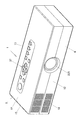
以下、本発明の実施形態を図に基づいて詳説する。図1は、プロジェクタ1の外観斜視図である。なお、本実施例において、プロジェクタ1における左右とは投影方向に対しての左右方向を示し、前後とはプロジェクタ1の投影方向及び光線束の進行方向に対しての前後方向を示す。
Hereinafter, the embodiments of the present invention will be explained in detail with reference to FIG. FIG. 1 is an external perspective view of the projector 1. In this embodiment, left and right in the projector 1 indicate the left and right direction with respect to the projection direction, and front and rear indicate the projection direction of the projector 1 and the front and rear direction with respect to the traveling direction of the light beam.
プロジェクタ1は、図1に示すように、略直方体形状をした手乗りサイズの小型プロジェクタ1であって、上ケース5と下ケース6により内部を覆うようにして構成されている。そして、プロジェクタ筐体の前方に位置する上ケース5と下ケース6とが嵌合されてなる正面板12には、略中央にレンズ鏡筒225が配置され、右側板15近傍に吸気孔18が形成されている。
As shown in FIG. 1, the projector 1 is a hand-held small projector 1 having a substantially rectangular parallelepiped shape, and is configured to cover an inside with an upper case 5 and a
また、プロジェクタ筐体の上ケース5によって形成される上面板11にはキー/インジケータ部37が設けられ、このキー/インジケータ部37には、電源スイッチキーや電源のオン又はオフを報知するパワーインジケータ、投影のオン、オフを切りかえる投影スイッチキー、光源ユニットや表示素子又は制御回路等が過熱したときに報知をする過熱インジケータ等のキーやインジケータが配置されている。さらに、プロジェクタ筐体の後方や側方に位置する上ケース5と下ケース6とが嵌合されてなる背面板13や右側板15には、USB端子や電源アダプタプラグ、メモリカードの挿入口等の各種端子が設けられている。
Further, a key /
次に、このプロジェクタ1の内部構造について述べる。図2は、プロジェクタ1の内部構造を示す平面模式図である。プロジェクタ1は、図2に示すように、中央部分に光源ユニット60を備え、光源ユニット60の左側方に投影側光学系が内装されたレンズ鏡筒225を備え、レンズ鏡筒225と左側板14との間にバッテリー55を備えている。また、プロジェクタ1は、レンズ鏡筒225と背面板13との間におけるバッテリー55の近傍に、左側板14と平行に配置されたDMD等の表示素子51を備えている。さらに、プロジェクタ1は、光源ユニット60の下方に主制御回路基板241を備え、レンズ鏡筒225とバッテリー55との間に電源制御回路基板242を備えている。
Next, the internal structure of the projector 1 will be described. FIG. 2 is a schematic plan view showing the internal structure of the projector 1. As shown in FIG. 2, the projector 1 includes a
また、プロジェクタ1は、光源ユニット60及びレンズ鏡筒225と背面板13との間に、光源ユニット60からの射出光を表示素子51に照射し、かつ、表示素子51で反射されたオン光の光軸を投影側光学系の光軸に一致させて投影側光学系に向かって射出する導光光学系170を備えている。また、光源ユニット60と右側板15との間には、背面板13側から順に、電源コネクタ80、後述する赤色光源121用のヒートシンク190、後述する励起光源71及び青色光源301用のヒートシンク130、冷却ファン261を備えている。
In addition, the projector 1 irradiates the
そして、光源ユニット60は、冷却ファン261の近傍であって正面板12の近傍に配置された励起光照射装置70と、励起光照射装置70とレンズ鏡筒225との間に配置された青色光源装置300と、電源コネクタ80の近傍であって背面板13の近傍に配置された蛍光発光装置100と、励起光照射装置70と蛍光発光装置100との間に配置された赤色光源装置120と、光源ユニット60から射出される赤色、緑色及び青色波長帯域光を導光光学系170まで導光する光源側光学系140と、から構成される。
The
励起光照射装置70は、光軸が左側板14と平行とされた2個の励起光源71と、各励起光源71の光軸上に配置されたコリメータレンズ73と、を備える。この励起光源71は、青色レーザ発光器であり、蛍光発光装置100に向けて青色波長帯域のレーザ光線を射出する。また、励起光源71は、励起光源71用の基板を介してヒートシンク130と接触しており、このヒートシンク130によって冷却される。
The excitation
蛍光発光装置100は、周方向に緑色蛍光体層が敷設された蛍光ホイール101と、蛍光ホイール101を回転駆動するホイールモータ105と、を備える。そして、蛍光ホイール101は、表面が鏡面加工されており、この鏡面上に円環状の緑色蛍光体層が周方向に敷設されてなる。また、緑色蛍光体層は、耐熱性及び透光性の高いシリコン樹脂等のバインダと、このバインダに均一に散りばめられた緑色蛍光体と、から形成されている。この緑色蛍光体層は、励起光源71から射出されたレーザ光線を励起光として緑色の蛍光光を励起光の入射面と同一の面から射出する。ホイールモータ105は、後述するモータ制御手段によって制御されており、モータ制御手段からの指示にしたがって蛍光ホイール101を回転又は停止させる。なお、この蛍光発光装置100における、モータ制御に関しての詳細な説明は後述する。
The fluorescent
赤色光源装置120は、光軸が正面板12と平行とされた赤色光源121を備える。この赤色光源121は、赤色発光ダイオードであり、ヒートシンク190によって冷却される。また、青色光源装置300は、光軸が励起光源71と平行とされた青色光源301を備える。この青色光源301は、青色発光ダイオードであり、ヒートシンク130によって冷却される。
The red
光源側光学系140は、励起光照射装置70からの射出光及び蛍光ホイール101からの蛍光光を集光する集光レンズ110と、赤色光源121からの射出光を集光する集光レンズ125と、青色光源301からの射出光を集光する集光レンズ305と、励起光照射装置70及び赤色光源装置120からの射出光を透過し、蛍光発光装置100による発光光を反射する第一ダイクロイックミラー141と、赤色光源装置120からの射出光、及び、蛍光発光装置100による発光光を反射し、青色光源装置300からの射出光を透過する第二ダイクロイックミラー142と、から構成される。
The light source side
集光レンズ110,125,305は、複数のレンズが組み合わされることにより一つの集光レンズとして構成されている。また、第一ダイクロイックミラー141は、励起光照射装置70(又は蛍光発光装置100)の光軸と赤色光源装置120の光軸とが交差する位置に配置されている。さらに、第二ダイクロイックミラー142は、赤色光源装置120の光軸と青色光源装置300の光軸とが交差する位置に配置されている。
The
そして、このような構成とされた光源ユニット60において、赤色波長帯域の光源光は赤色光源121によって生成され、緑色波長帯域の光源光は励起光照射装置70からの射出光を励起光として発光する蛍光ホイール101によって生成され、青色波長帯域の光源光は青色光源301によって生成される。そして、各波長帯域光は、光源側光学系140によって導光光学系170のマイクロレンズアレイ171に照射される。
In the
導光光学系170は、マイクロレンズアレイ171と、光源ユニット60からの射出光の光軸を表示素子51に向かって変更する光軸変更ミラー173と、光軸変更ミラー173とマイクロレンズアレイ171との間に配置された集光レンズ172と、光軸変更ミラー173で変更された光軸上に位置する集光レンズ174と、プリズム175と、から構成されている。マイクロレンズアレイ171は、光源ユニット60から射出された略円形断面の光線束を、表示素子51の形状に合わせた長方形断面の光線束に変換する。プリズム175は、表示素子51に光源光を照射するコンデンサレンズとして、及び、表示素子51で生成された投影光をレンズ鏡筒225に内装された投影側光学系の光軸と一致させるように光軸を変更する光軸変換装置として機能する。
The light guide
レンズ鏡筒225に内装された投影側光学系は、固定レンズ群や可動レンズ群によって構成されている。また、バッテリー55は、プロジェクタ1の駆動電源であり、商用電源の接続により充電可能な2次電池である。なお、バッテリー55は、リチウムイオン電池、ニッケル水素電池等の2次電池を適用可能である。そして、本実施例のプロジェクタ1は、電気コード等を接続していなくとも、このバッテリーの電力によって投影可能とされている。
The projection-side optical system built in the
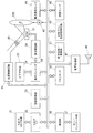
次に、プロジェクタ1のプロジェクタ制御手段について図3の機能ブロック図を用いて述べる。プロジェクタ制御手段は、制御部38、入出力インターフェース22、画像変換部23、表示エンコーダ24、表示駆動部26等から構成される。この制御部38は、プロジェクタ1内の各回路の動作制御を司るものであって、演算装置としてのCPUや各種セッティング等の動作プログラムを固定的に記憶したROM及びワークメモリとして使用されるRAM等により構成されている。
Next, the projector control means of the projector 1 will be described using the functional block diagram of FIG. The projector control means includes a
そして、このプロジェクタ制御手段により、入出力コネクタ部21から入力された各種規格の画像信号は、入出力インターフェース22、システムバス(SB)を介して画像変換部23で表示に適した所定のフォーマットの画像信号に統一するように変換された後、表示エンコーダ24に出力される。
Then, the image signal of various standards input from the input /
また、表示エンコーダ24は、入力された画像信号をビデオRAM25に展開記憶させた上でこのビデオRAM25の記憶内容からビデオ信号を生成して表示駆動部26に出力する。
The
表示駆動部26は、表示素子制御手段として機能するものであり、表示エンコーダ24から出力された画像信号に対応して適宜フレームレートで空間的光変調素子(SOM)である表示素子51を駆動するものであり、光源ユニット60から射出された光線束、即ち光源ユニット60の光源側光学系140により所定の一面に集光された光線束を導光光学系170を介して表示素子51に照射することにより、表示素子51の反射光で光像を形成し、投影側光学系を介して図示しないスクリーンに画像を投影表示する。また、この投影側光学系の可動レンズ群235は、レンズモータ45によりズーム調整やフォーカス調整のための駆動が行われる。
The
また、画像圧縮伸長部31は、再生時にメモリカード32に記録された画像データを読み出し、一連の動画を構成する個々の画像データを1フレーム単位で伸長し、この画像データを画像変換部23を介して表示エンコーダ24に出力し、メモリカード32に記憶された画像データに基づいて動画等の表示を可能とする処理を行なう。
The image compression /
そして、筐体の上ケース5に設けられるキー/インジケータ部37からの操作信号は、直接に制御部38に送出される。なお、制御部38にはシステムバス(SB)を介して音声処理部47が接続されている。この音声処理部47は、PCM音源等の音源回路を備えており、投影モード及び再生モード時には音声データをアナログ化し、スピーカ48を駆動して拡声放音させる。
Then, an operation signal from the key /
また、制御部38は、光源制御手段としての光源制御回路41を制御している。この光源制御回路41は、画像生成時に要求される所定波長帯域の光源光が光源ユニット60から射出されるように、光源ユニット60の励起光照射装置70、赤色光源装置120及び青色光源装置300の発光を個別に制御する。また、光源制御回路41は、制御部38に制御されてホイールモータ105の停止、回転の制御を行うモータ制御手段としても機能する。さらに、制御部38は、冷却ファン駆動制御回路43に光源ユニット60等に設けた複数の温度センサによる温度検出を行わせ、この温度検出の結果から冷却ファンの回転速度を制御させている。
The
さらに、本実施例のプロジェクタ制御手段は、光源ユニット60からの射出光の照度を測定する照度測定手段としての照度センサ42や、励起光源71を流れる電流を測定する励起電流測定手段としての電流測定センサ44を備える。そして、制御部38は、照度センサ42から送出された各波長帯域光の出力に関する情報を基に、光源制御回路41を制御して、励起光源71、赤色光源121及び青色光源301に流す電流を調整する。
Further, the projector control means of the present embodiment includes an
そして、本実施例のプロジェクタ1は、省電力モードと、通常投影モードと、高輝度投影モードと、の3つの投影モードでの投影が可能とされている。省電力モードとは、励起光源71、赤色光源121及び青色光源301からの出力を抑えて投影するモードであり、高輝度投影モードとは、励起光源71、赤色光源121及び青色光源301からの出力を高くして投影するモードであり、通常投影モードとは、省電力モードと高輝度投影モードとの中間のモードである。
The projector 1 of the present embodiment is capable of projection in three projection modes: a power saving mode, a normal projection mode, and a high brightness projection mode. The power saving mode is a mode in which the output from the
このような投影モードを実現するために、制御部38は、各モード時における各光源71,121,301からの出力に関する情報が予め記憶された出力情報記憶手段として、及び、各モードでの投影時における各光源71,121,301に流す電流に関する情報が予め記憶された電流情報記憶手段として機能する。
In order to realize such a projection mode, the
そして、制御部38は、光源制御回路41を制御して、設定されている投影モードに応じて、記憶されている情報を基に各光源71,121,301を、複数の輝度モードで点灯させる。つまり、制御部38は、省電力モードの場合に各光源71,121,301を低輝度モードで点灯させ、通常投影モードの場合に各光源71,121,301を中輝度モードで点灯させ、高輝度投影モードの場合に各光源71,121,301を高輝度モードで点灯させる。また、制御部38は、照度センサ42から送出される各光源71,121,301の出力情報と予め記憶された出力情報とを比較し、出力に差がある場合には、照度センサ42から送出される出力情報が予め記憶された出力情報と同一になるよう各光源71,121,301に流す電流を調整する。このように制御部38が光源制御回路41を制御することにより、各光源71,121,301のいずれかに経年劣化等による輝度の低下が生じても製品出荷当初の輝度バランスを保つことができる。
Then, the
このような構成とされた本実施例のプロジェクタ1では、バッテリー駆動で長時間の投影を可能にするため、投影時の電力消費量を削減する必要がある。本実施例のプロジェクタ1では、蛍光体層の一部に高出力な励起光が照射されることで蛍光体が加熱劣化や燃焼により破損し、発光量の減少が生じることを防止するために蛍光ホイール101を回転させる構成としている。しかしながら、この蛍光ホイール101を回転駆動するホイールモータ105の駆動電流は、大きな電力消費源となる。そこで、本実施例のプロジェクタ1では、蛍光体に燃焼等の損傷が生じない程度の出力のときには蛍光ホイール101の回転を停止させる制御を行うことにより、電力消費量の削減を行っている。
In the projector 1 of this embodiment having such a configuration, it is necessary to reduce the power consumption during projection in order to enable long-time projection by battery driving. In the projector 1 of this embodiment, in order to prevent the phosphor from being damaged due to heat deterioration or combustion due to irradiation of a part of the phosphor layer with high-power excitation light, the emission amount is reduced. The
そして、本実施例のプロジェクタ1は、電力消費量の削減を実現するために、ホイールモータ105の制御情報が記憶された制御情報記憶手段と、制御情報記憶手段に記憶された情報を基にホイールモータ105を制御するモータ制御手段と、励起光源71に流れる電流を測定する励起電流測定手段と、を有している。なお、この制御情報記憶手段及びモータ制御手段は、制御部38の一機能であり、励起電流測定手段は、電流測定センサ44である。
The projector 1 according to the present embodiment is configured so that the control information storage unit that stores the control information of the
この制御情報記憶手段には、省電力モード及び通常投影モードの時にはホイールモータ105停止、高輝度投影モードの時にはホイールモータ105駆動の旨の制御情報が記憶されている。また、制御情報記憶手段には、ホイールモータ105を停止させる、又は、駆動を開始させるときの励起光源71の駆動電流である境界駆動電流情報が記憶されている。
The control information storage means stores control information indicating that the
そして、モータ制御手段は、図4に示す制御フローにしたがってホイールモータ105を制御している。すなわち、モータ制御手段は、投影モードが省電力モード又は通常投影モードであるか否かを判定する投影モード判定処理(ステップS101)を実行する。そして、投影モード判定処理(ステップS101)において投影モードが省電力モード又は通常投影モードであった場合、モータ制御手段は、励起光源71の駆動電流が制御情報記憶手段に記憶された境界駆動電流未満であるか否かを判定する駆動電流判定処理(ステップS105)を実行する。
The motor control means controls the
駆動電流判定処理(ステップS105)において駆動電流が境界駆動電流未満であった場合、モータ制御手段は、ホイールモータ105を停止させるモータ停止処理(ステップS107)を実行する。一方、投影モード判定処理(ステップS101)において高輝度投影モードであった場合、及び、駆動電流判定処理(ステップS105)において駆動電流が境界駆動電流以上であった場合、モータ制御手段は、ホイールモータ105を駆動させるモータ駆動処理(ステップS110)を実行する。そして、モータ停止処理(ステップS107)及びモータ駆動処理(ステップS110)の後、モータ制御手段は、以上の各処理を投影終了時まで繰り返し実行する。
If the drive current is less than the boundary drive current in the drive current determination process (step S105), the motor control means executes a motor stop process (step S107) for stopping the
すなわち、本実施例のプロジェクタ1では、投影モードに応じてホイールモータ105の制御を行いつつ、励起光源71の駆動電流に応じてホイールモータ105を制御している。このように投影モードと駆動電流の両者を確認しながらホイールモータ105を制御するのは、本実施例のプロジェクタ1が、上述したように照度センサ42で測定した出力の情報に基づいて各光源71,121,301の駆動電流を制御しているため、省電力モードや通常投影モードであっても照度センサ42からの情報を基に制御した励起光源71の駆動電流あるいは励起光源71からの出力が高く、蛍光体に燃焼等が生じてしまう可能性があるためである。すなわち、投影モードと駆動電流の両者を確認しながらホイールモータ105を制御することにより、蛍光体の燃焼による破損を確実に防止することができる。
That is, in the projector 1 of this embodiment, the
なお、本実施例で使用している緑色蛍光体は、5.48W/mm2の出力で励起光が照射された場合には20msecで燃焼し、1.62W/mm2の出力で励起光が照射された場合には燃焼が生じない。よって、少なくとも5.48W/mm2のレーザ光線が出力される駆動電流が励起光源71に流れている状態では蛍光ホイール101を回転させる必要があり、一方、1.62W/mm2のレーザ光線が出力される駆動電流が励起光源71に流れている状態では蛍光ホイール101を停止させることができる。
Incidentally, a green phosphor is used in this example, burned in 20msec when the excitation light at the output of 5.48W / mm 2 is irradiated, the excitation light at the output of 1.62W / mm 2 Combustion does not occur when irradiated. Therefore, it is necessary to rotate the
本実施例のプロジェクタ1によれば、蛍光体に燃焼等の損傷が生じない範囲でホイールモータ105の停止、又は、駆動の制御を行うモータ制御手段を備えることにより、蛍光体の燃焼等の損傷を防止しつつ、電力消費を抑えることができる。すなわち、投影時にホイールモータ105を停止させることにより大きな電力消費源であるホイールモータ105の駆動電力を減らすことができ、バッテリー55の電力による投影時の投影時間を長くできるため、使い勝手がよく、かつ、小型のプロジェクタを提供できることとなる。
According to the projector 1 of the present embodiment, the phosphor is burned or damaged by providing the motor control means for controlling the driving or stopping of the
また、本実施例のプロジェクタ1によれば、励起電流測定手段と、制御情報記憶手段と、を備えることにより、励起光源71を流れる駆動電流に応じてホイールモータ105の停止、駆動を制御できることとなり、蛍光体に燃焼等が生じることを確実に防止しつつ、電力消費を抑えることができる。
Further, according to the projector 1 of the present embodiment, by providing the excitation current measuring means and the control information storage means, the stop and drive of the
さらに、制御情報記憶手段に境界駆動電流情報が予め記憶されていることにより、モータ制御手段によるホイールモータ105の停止、駆動の制御が容易に実現できるため、蛍光体の燃焼等を防止しつつ、電力消費を削減したプロジェクタ1を容易に提供できることとなる。
Furthermore, since the boundary drive current information is stored in advance in the control information storage means, it is possible to easily control the stop and drive of the
また、投影モードに応じてホイールモータ105の停止、駆動を制御することにより、複数の投影モードを備えたあらゆるプロジェクタ1において、電力消費量の削減を容易に実現できることとなる。
Further, by controlling the stop and driving of the
なお、本実施例では、制御情報記憶手段に境界駆動電流情報を記憶させ、投影モードと境界駆動電流情報との両者を確認しながらホイールモータ105の停止、駆動を制御する構成としているが、制御情報記憶手段に、励起光源71に流れる駆動電流と蛍光ホイール101の回転速度とに関する情報を記憶させ、駆動電流が高い場合には蛍光ホイール101の回転速度を速くし、駆動電流が低い場合には蛍光ホイール101の回転速度を遅くする、又は、停止させる構成とすることもできる。
In this embodiment, the boundary drive current information is stored in the control information storage means, and the stop and drive of the
このように励起光源71に流れる駆動電流にしたがって蛍光ホイール101の回転速度をアナログ的に制御する構成とした場合であっても、ホイールモータ105の駆動に必要な電力消費量を削減できるため、バッテリー55の電力で長時間投影が可能な小型プロジェクタを提供できることとなる。
In this way, even when the rotation speed of the
また、制御情報記憶手段に、ホイールモータ105を停止させる、又は、駆動させる境界となる励起光源71の出力の情報である境界出力情報を記憶させ、上述した照度測定手段としての照度センサ42から送出される励起光源71の出力情報を基にホイールモータ105を制御する構成としてもよい。つまり、照度センサ42から送出された励起光源71の出力情報と境界出力情報とを対比して、ホイールモータ105を制御する構成とすることもできる。このように、励起光源71の出力を基にホイールモータ105を制御する構成とした場合も、上述した各実施例と同様に、蛍光体の燃焼を防止しつつホイールモータ105の駆動に必要な電力消費量を削減できるため、バッテリー55の電力で長時間投影が可能な小型プロジェクタを提供できることとなる。
In addition, the control information storage means stores boundary output information, which is information on the output of the
なお、上述した実施例では、緑色波長帯域光のみ蛍光ホイール101を用いて生成しているも、他の波長帯域光が周方向に敷設された蛍光ホイールを備える光源ユニットにおいても、同様のモータ制御により電力消費量の削減が可能である。つまり、蛍光ホイールとホイールモータを備えたあらゆる照明装置、光源装置において同様の構成により電力消費量の削減が可能となる。すなわち、本発明は、以上の実施例に限定されるものでなく、発明の要旨を逸脱しない範囲で自由に変更、改良が可能である。
In the embodiment described above, only the green wavelength band light is generated using the
1 プロジェクタ
5 上ケース 6 下ケース
11 上面板 12 正面板
13 背面板 14 左側板
15 右側板
18 吸気孔 21 入出力コネクタ部
22 入出力インターフェース 23 画像変換部
24 表示エンコーダ 25 ビデオRAM
26 表示駆動部 31 画像圧縮伸長部
32 メモリカード 37 キー/インジケータ部
38 制御部
41 光源制御回路 42 照度センサ
43 冷却ファン駆動制御回路 44 電流測定センサ
45 レンズモータ 47 音声処理部
48 スピーカ 51 表示素子
55 バッテリー 60 光源ユニット
70 励起光照射装置 71 励起光源
73 コリメータレンズ 80 電源コネクタ
100 蛍光発光装置 101 蛍光ホイール
105 ホイールモータ 110 集光レンズ
120 赤色光源装置 121 赤色光源
125 集光レンズ 130 ヒートシンク
140 光源側光学系 141 第一ダイクロイックミラー
142 第二ダイクロイックミラー 170 導光光学系
171 マイクロレンズアレイ 172 集光レンズ
173 光軸変更ミラー 174 集光レンズ
175 プリズム 190 ヒートシンク
225 レンズ鏡筒 235 可動レンズ群
241 主制御回路基板 242 電源制御回路基板
261 冷却ファン 300 青色光源装置
301 青色光源 305 集光レンズ
1 Projector
5
13
15 Right side plate
18
22 I / O interface 23 Image converter
24
26
32
38 Control unit
41 Light
43 Cooling fan
45
48
55
70 Excitation
73
100 Fluorescent
105
120 Red
125
140 Light source side
142 Second
171
173 Optical
175
225
241 Main
261
301 Blue
Claims (9)
該励起光源からの射出光を励起光として発光する蛍光体層が周方向に敷設された蛍光ホイールと、
該蛍光ホイールを駆動するホイールモータと、
前記蛍光体層に前記励起光源による励起光が照射されている状態で、前記ホイールモータを停止させるか駆動させるかを決定するモータ制御手段と、
を備えることを特徴とする光源ユニット。 An excitation light source;
A fluorescent wheel in which a phosphor layer emitting light emitted from the excitation light source as excitation light is laid in the circumferential direction;
A wheel motor for driving the fluorescent wheel;
Motor control means for determining whether to stop or drive the wheel motor in a state where the phosphor layer is irradiated with excitation light from the excitation light source ;
A light source unit comprising:
前記励起光源に流れる駆動電流の値と前記ホイールモータの停止又は駆動との関係に関する情報が記憶された制御情報記憶手段と、をさらに備え、
前記モータ制御手段は、前記励起電流測定手段から送出された駆動電流の値と前記制御情報記憶手段に記憶された情報とを対比し、前記制御情報記憶手段に記憶された情報を基に前記ホイールモータを停止させるか駆動させるかを決定することを特徴とする請求項1に記載の光源ユニット。 Excitation current measuring means for measuring a drive current flowing through the excitation light source;
Further comprising a control information storage means in which information is stored on the relationship between stopping or driving value and the wheel motor drive current flowing through the excitation light source,
The motor control means compares the value of the drive current sent from the excitation current measuring means with the information stored in the control information storage means, and based on the information stored in the control information storage means, the wheel The light source unit according to claim 1, wherein it is determined whether to stop or drive the motor.
前記モータ制御手段は、前記励起光源を流れる駆動電流の値が前記境界駆動電流未満の場合に前記ホイールモータを停止させると決定し、前記励起光源を流れる駆動電流の値が前記境界駆動電流以上の場合に前記ホイールモータを駆動させると決定することを特徴とする請求項2に記載の光源ユニット。 The control information storage means stores boundary drive current information, which is information of boundary drive current flowing through the excitation light source, which is a condition for stopping or driving the wheel motor,
The motor control means determines that the wheel motor is stopped when the value of the drive current flowing through the excitation light source is less than the boundary drive current, and the value of the drive current flowing through the excitation light source is equal to or greater than the boundary drive current. the light source unit according to claim 2, wherein the determining that drives the wheel motors when.
前記モータ制御手段は、前記励起光源を流れる駆動電流の値に応じた前記蛍光ホイールの回転速度となるように前記ホイールモータを制御することを特徴とする請求項2又は請求項3に記載の光源ユニット。 The control information storage means stores information related to the drive current flowing through the excitation light source and the rotation speed of the fluorescent wheel,
4. The light source according to claim 2, wherein the motor control unit controls the wheel motor so as to achieve a rotation speed of the fluorescent wheel according to a value of a drive current flowing through the excitation light source. unit.
青色波長帯域光を射出する青色光源と、
前記励起光源、前記赤色光源及び前記青色光源を時分割制御する光源制御手段と、
をさらに備えることを特徴とする請求項1乃至請求項4のいずれか1項に記載の光源ユニット。 A red light source which emits red color wavelength band light,
A blue light source that emits blue wavelength band light;
Before SL excitation light source, a light source control means for time division control the red light source and the blue light source,
The light source unit according to claim 1, further comprising:
当該光源ユニットからの出力に関する情報が予め記憶された出力情報記憶手段と、Output information storage means in which information relating to the output from the light source unit is stored in advance;
前記照度測定手段から送出される出力情報と前記出力情報記憶手段に予め記憶された出力情報とを比較し、前記照度測定手段から送出される出力情報が予め記憶された出力情報と同一になるよう当該光源ユニットに流す電流を調整する電流制御手段と、The output information sent from the illuminance measuring means is compared with the output information stored in advance in the output information storage means so that the output information sent from the illuminance measuring means becomes the same as the output information stored in advance. Current control means for adjusting the current flowing through the light source unit;
をさらに備えることを特徴とする請求項1乃至請求項5の何れかに記載の光源ユニット。The light source unit according to claim 1, further comprising:
前記モータ制御手段は、前記輝度モードに応じて前記ホイールモータを停止させるか駆動させるかを決定することを特徴とする請求項1乃至請求項6のいずれか1項に記載の光源ユニット。 Provided with multiple brightness modes with different brightness of emitted light source light,
Before SL motor control means includes a light source unit according to any one of claims 1 to 6, characterized in that determining whether to drive or stop the wheel motor in accordance with the brightness mode.
表示素子と、
前記光源ユニットからの射出光を前記表示素子まで導光する導光光学系と、
前記表示素子で生成された投影光を投影する投影側光学系と、
を備え、
前記光源ユニットが、請求項1乃至請求項8の何れかに記載の光源ユニットであることを特徴とするプロジェクタ。
And a light source unit,
A display element;
A light guide optical system for guiding light emitted from the light source unit to the display element;
A projection-side optical system that projects the projection light generated by the display element;
With
The projector according to claim 1, wherein the light source unit is the light source unit according to claim 1 .
Priority Applications (6)
| Application Number | Priority Date | Filing Date | Title |
|---|---|---|---|
| JP2010082695A JP4936091B2 (en) | 2010-03-31 | 2010-03-31 | Light source unit and projector |
| TW100110508A TWI425297B (en) | 2010-03-31 | 2011-03-28 | Light source unit and projector |
| KR1020110028719A KR101227997B1 (en) | 2010-03-31 | 2011-03-30 | Light source unit and projector |
| US13/076,669 US8500289B2 (en) | 2010-03-31 | 2011-03-31 | Light source unit including a luminescent wheel that performs control to rotate or stop the wheel while light is emitted onto it and projector |
| CN2011100780353A CN102207668B (en) | 2010-03-31 | 2011-03-31 | Light source unit and projector |
| DE102011006536.9A DE102011006536B4 (en) | 2010-03-31 | 2011-03-31 | Light source unit and projector |
Applications Claiming Priority (1)
| Application Number | Priority Date | Filing Date | Title |
|---|---|---|---|
| JP2010082695A JP4936091B2 (en) | 2010-03-31 | 2010-03-31 | Light source unit and projector |
Publications (3)
| Publication Number | Publication Date |
|---|---|
| JP2011215332A JP2011215332A (en) | 2011-10-27 |
| JP2011215332A5 JP2011215332A5 (en) | 2011-12-08 |
| JP4936091B2 true JP4936091B2 (en) | 2012-05-23 |
Family
ID=44650262
Family Applications (1)
| Application Number | Title | Priority Date | Filing Date |
|---|---|---|---|
| JP2010082695A Active JP4936091B2 (en) | 2010-03-31 | 2010-03-31 | Light source unit and projector |
Country Status (6)
| Country | Link |
|---|---|
| US (1) | US8500289B2 (en) |
| JP (1) | JP4936091B2 (en) |
| KR (1) | KR101227997B1 (en) |
| CN (1) | CN102207668B (en) |
| DE (1) | DE102011006536B4 (en) |
| TW (1) | TWI425297B (en) |
Cited By (1)
| Publication number | Priority date | Publication date | Assignee | Title |
|---|---|---|---|---|
| US10371937B2 (en) | 2017-02-10 | 2019-08-06 | Canon Kabushiki Kaisha | Projection display apapratus |
Families Citing this family (30)
| Publication number | Priority date | Publication date | Assignee | Title |
|---|---|---|---|---|
| JP4973962B2 (en) * | 2010-03-31 | 2012-07-11 | カシオ計算機株式会社 | Light source device and projector |
| JP5223941B2 (en) * | 2011-03-28 | 2013-06-26 | カシオ計算機株式会社 | Projection device |
| CN102854725A (en) * | 2011-06-28 | 2013-01-02 | 中强光电股份有限公司 | Projection device |
| JP6098074B2 (en) | 2011-10-31 | 2017-03-22 | 株式会社リコー | Projection display device |
| JP5799756B2 (en) | 2011-11-02 | 2015-10-28 | セイコーエプソン株式会社 | projector |
| CN102645828B (en) * | 2011-12-01 | 2014-11-05 | 深圳市光峰光电技术有限公司 | Projecting device, light source system for displaying and control methods thereof |
| JP5927011B2 (en) * | 2012-04-10 | 2016-05-25 | オリンパス株式会社 | Endoscope device |
| JP6229316B2 (en) * | 2013-06-03 | 2017-11-15 | セイコーエプソン株式会社 | Light source device and projector |
| JP6245469B2 (en) * | 2013-09-20 | 2017-12-13 | カシオ計算機株式会社 | Light source unit and projector |
| JP2015094860A (en) * | 2013-11-12 | 2015-05-18 | 株式会社リコー | Illumination light source device and image projection device |
| JP6344596B2 (en) * | 2014-03-17 | 2018-06-20 | カシオ計算機株式会社 | Light source device and projection device |
| JP6424444B2 (en) * | 2014-03-27 | 2018-11-21 | セイコーエプソン株式会社 | Projector control method |
| JP6460370B2 (en) * | 2014-05-22 | 2019-01-30 | カシオ計算機株式会社 | Light source device and image projection device |
| JP2016012116A (en) * | 2014-06-02 | 2016-01-21 | カシオ計算機株式会社 | Light source device and projection device |
| CN105301880B (en) * | 2014-06-02 | 2017-05-03 | 卡西欧计算机株式会社 | Light source device and projection device having the same |
| DE102014221668B4 (en) * | 2014-10-24 | 2022-07-07 | Coretronic Corporation | lighting device |
| TWI557493B (en) * | 2015-01-22 | 2016-11-11 | 中強光電股份有限公司 | Wavelength conversion module and projector |
| JP6070793B2 (en) * | 2015-08-21 | 2017-02-01 | セイコーエプソン株式会社 | Projector control method and projector |
| WO2018083895A1 (en) * | 2016-11-02 | 2018-05-11 | ソニー株式会社 | Projection-type display device and method for controlling same |
| CN106502035A (en) * | 2016-11-18 | 2017-03-15 | 四川长虹电器股份有限公司 | A kind of laser source system |
| MX2017008919A (en) * | 2017-07-05 | 2018-03-01 | Gabriela Reyes Fuchs Carmen | Process for forming a color image of incinerated materials by microscopy techniques. |
| EP3936385A1 (en) * | 2017-10-13 | 2022-01-12 | Koito Manufacturing Co., Ltd. | Vehicle lamp |
| WO2019111326A1 (en) | 2017-12-05 | 2019-06-13 | Necディスプレイソリューションズ株式会社 | Projector, rotational phase control device, program for rotational phase control device, and method for controlling wheel speed |
| CN111624838A (en) * | 2019-02-28 | 2020-09-04 | 中强光电股份有限公司 | Projection system and driving method of projection system |
| JP7071703B2 (en) * | 2020-03-03 | 2022-05-19 | カシオ計算機株式会社 | Light source device, projection device and light source control method |
| US11407298B1 (en) | 2021-11-15 | 2022-08-09 | Amos Power, Inc. | Removable battery unit for an electric vehicle |
| US11364959B1 (en) | 2021-12-27 | 2022-06-21 | Amos Power, Inc. | Modular robotic vehicle |
| USD1014569S1 (en) | 2022-04-01 | 2024-02-13 | Amos Power, Inc. | Robotic vehicle |
| USD1014573S1 (en) | 2022-04-01 | 2024-02-13 | Amos Power, Inc. | Removable track unit for a robotic vehicle |
| US11547035B1 (en) | 2022-05-24 | 2023-01-10 | Amos Power, Inc. | Lift assist for an electrically driven hitch on an robotic vehicle |
Family Cites Families (11)
| Publication number | Priority date | Publication date | Assignee | Title |
|---|---|---|---|---|
| JP2002333671A (en) * | 2001-05-07 | 2002-11-22 | Matsushita Electric Ind Co Ltd | Color reproducibility correction device for projector |
| JP4829470B2 (en) * | 2003-05-14 | 2011-12-07 | Necディスプレイソリューションズ株式会社 | Projection display |
| JP3888465B2 (en) * | 2004-05-26 | 2007-03-07 | セイコーエプソン株式会社 | Image processing system, projector, and image processing method |
| JP2006154002A (en) * | 2004-11-25 | 2006-06-15 | Matsushita Electric Works Ltd | Projector device |
| JP4802512B2 (en) * | 2005-02-25 | 2011-10-26 | カシオ計算機株式会社 | Projection apparatus, operation control method and program for projection apparatus |
| JP2008181044A (en) * | 2007-01-26 | 2008-08-07 | Seiko Epson Corp | Projector and game machine |
| JP2009085977A (en) * | 2007-09-27 | 2009-04-23 | Brother Ind Ltd | Projector |
| JP4662185B2 (en) * | 2008-05-15 | 2011-03-30 | カシオ計算機株式会社 | Light source device and projector |
| CN101750855B (en) * | 2008-12-19 | 2011-11-16 | 绎立锐光科技开发(深圳)有限公司 | Protective method and device of projection system and tinting device |
| JP4678556B2 (en) * | 2009-03-17 | 2011-04-27 | カシオ計算機株式会社 | Light emitting device, light source device, and projector using the light source device |
| JP4873276B2 (en) * | 2009-10-28 | 2012-02-08 | カシオ計算機株式会社 | Light source unit and projector |
-
2010
- 2010-03-31 JP JP2010082695A patent/JP4936091B2/en active Active
-
2011
- 2011-03-28 TW TW100110508A patent/TWI425297B/en active
- 2011-03-30 KR KR1020110028719A patent/KR101227997B1/en active IP Right Grant
- 2011-03-31 DE DE102011006536.9A patent/DE102011006536B4/en active Active
- 2011-03-31 CN CN2011100780353A patent/CN102207668B/en active Active
- 2011-03-31 US US13/076,669 patent/US8500289B2/en active Active
Cited By (1)
| Publication number | Priority date | Publication date | Assignee | Title |
|---|---|---|---|---|
| US10371937B2 (en) | 2017-02-10 | 2019-08-06 | Canon Kabushiki Kaisha | Projection display apapratus |
Also Published As
| Publication number | Publication date |
|---|---|
| JP2011215332A (en) | 2011-10-27 |
| TWI425297B (en) | 2014-02-01 |
| TW201142472A (en) | 2011-12-01 |
| KR101227997B1 (en) | 2013-02-01 |
| CN102207668A (en) | 2011-10-05 |
| CN102207668B (en) | 2012-11-21 |
| KR20110110007A (en) | 2011-10-06 |
| DE102011006536B4 (en) | 2019-05-29 |
| DE102011006536A1 (en) | 2011-10-06 |
| US20110242502A1 (en) | 2011-10-06 |
| US8500289B2 (en) | 2013-08-06 |
Similar Documents
| Publication | Publication Date | Title |
|---|---|---|
| JP4936091B2 (en) | Light source unit and projector | |
| JP5527594B2 (en) | Light source unit and projector | |
| JP4900736B2 (en) | Light source device and projector | |
| JP6202313B2 (en) | Fluorescent light emitting device and projector | |
| JP4756403B2 (en) | Light source device and projector | |
| JP5327529B2 (en) | Light source device and projector | |
| US8684537B2 (en) | Light source unit and projector for controlling illumination cycles of respective light sources and rotation of a luminescent wheel | |
| JP4711156B2 (en) | Light source device and projector | |
| JP5311137B2 (en) | Light source device and projector provided with light source device | |
| JP5910868B2 (en) | Light source device and projector | |
| JP5534336B2 (en) | Light source unit and projector | |
| JP2011154168A (en) | Light source unit and projector | |
| JP2016045302A (en) | Atypical lens, light source device and projection device | |
| JP2011170363A (en) | Light source device and projector | |
| JP5488563B2 (en) | Light source device and projector | |
| JP5780325B2 (en) | Light source device and projector | |
| JP6245469B2 (en) | Light source unit and projector | |
| JP5655911B2 (en) | Light source device and projector | |
| JP5408494B2 (en) | Projector, projector light source initial drive voltage setting method, and projector light source drive voltage setting method | |
| JP2018045111A (en) | Light source device and projection device | |
| JP2014062989A (en) | Light source device and method for lighting light source device and projector | |
| JP6094631B2 (en) | Light source device and projector | |
| JP2015045778A (en) | Light source device and projector | |
| JP2012078567A (en) | Gradation correction method for projector and projector | |
| JP2012042964A (en) | Light source unit and projector |
Legal Events
| Date | Code | Title | Description |
|---|---|---|---|
| A521 | Request for written amendment filed |
Free format text: JAPANESE INTERMEDIATE CODE: A523 Effective date: 20110913 |
|
| A621 | Written request for application examination |
Free format text: JAPANESE INTERMEDIATE CODE: A621 Effective date: 20110913 |
|
| A977 | Report on retrieval |
Free format text: JAPANESE INTERMEDIATE CODE: A971007 Effective date: 20120119 |
|
| TRDD | Decision of grant or rejection written | ||
| A01 | Written decision to grant a patent or to grant a registration (utility model) |
Free format text: JAPANESE INTERMEDIATE CODE: A01 Effective date: 20120126 |
|
| A01 | Written decision to grant a patent or to grant a registration (utility model) |
Free format text: JAPANESE INTERMEDIATE CODE: A01 |
|
| A61 | First payment of annual fees (during grant procedure) |
Free format text: JAPANESE INTERMEDIATE CODE: A61 Effective date: 20120208 |
|
| FPAY | Renewal fee payment (event date is renewal date of database) |
Free format text: PAYMENT UNTIL: 20150302 Year of fee payment: 3 |
|
| R150 | Certificate of patent or registration of utility model |
Ref document number: 4936091 Country of ref document: JP Free format text: JAPANESE INTERMEDIATE CODE: R150 Free format text: JAPANESE INTERMEDIATE CODE: R150 |