EP1600994A1 - Circuit breaker with delay mechanism - Google Patents
Circuit breaker with delay mechanism Download PDFInfo
- Publication number
- EP1600994A1 EP1600994A1 EP05010757A EP05010757A EP1600994A1 EP 1600994 A1 EP1600994 A1 EP 1600994A1 EP 05010757 A EP05010757 A EP 05010757A EP 05010757 A EP05010757 A EP 05010757A EP 1600994 A1 EP1600994 A1 EP 1600994A1
- Authority
- EP
- European Patent Office
- Prior art keywords
- circuit breaker
- inertia member
- condition
- spring
- switch
- Prior art date
- Legal status (The legal status is an assumption and is not a legal conclusion. Google has not performed a legal analysis and makes no representation as to the accuracy of the status listed.)
- Granted
Links
- 230000007246 mechanism Effects 0.000 title claims abstract description 46
- 230000003213 activating effect Effects 0.000 claims description 2
- 230000008859 change Effects 0.000 abstract description 7
- 239000004020 conductor Substances 0.000 description 5
- 230000001934 delay Effects 0.000 description 3
- 230000003111 delayed effect Effects 0.000 description 2
- 238000007373 indentation Methods 0.000 description 2
- 239000000463 material Substances 0.000 description 2
- 230000008901 benefit Effects 0.000 description 1
- 230000007423 decrease Effects 0.000 description 1
- 230000003247 decreasing effect Effects 0.000 description 1
- 230000000694 effects Effects 0.000 description 1
- 230000003993 interaction Effects 0.000 description 1
- 230000004048 modification Effects 0.000 description 1
- 238000012986 modification Methods 0.000 description 1
- 239000002991 molded plastic Substances 0.000 description 1
- 230000000717 retained effect Effects 0.000 description 1
- 238000011144 upstream manufacturing Methods 0.000 description 1
Images


Classifications
-
- H—ELECTRICITY
- H01—ELECTRIC ELEMENTS
- H01H—ELECTRIC SWITCHES; RELAYS; SELECTORS; EMERGENCY PROTECTIVE DEVICES
- H01H71/00—Details of the protective switches or relays covered by groups H01H73/00 - H01H83/00
- H01H71/10—Operating or release mechanisms
- H01H71/12—Automatic release mechanisms with or without manual release
- H01H71/44—Automatic release mechanisms with or without manual release having means for introducing a predetermined time delay
- H01H71/446—Automatic release mechanisms with or without manual release having means for introducing a predetermined time delay making use of an inertia mass
Definitions
- the present invention relates generally to circuit breakers and, more particularly, to a circuit breaker having a delay mechanism that slightly delays the actuation of a switch upon moving the circuit breaker from an OFF condition to an ON condition.
- a power distribution system often includes circuit breakers in a cascaded configuration that provides coordinated operation such that upon the occurrence of a fault condition or other condition requiring an interruption of power the circuit breaker in the closest upstream location trips. Such a system is provided in order to limit the power interruption in other areas that are unaffected by the fault or other condition.
- circuit breakers in a power distribution system are in an OFF condition while other circuit breakers in the power distribution system are in an ON condition. If a fault condition arises upon switching the OFF circuit breaker to an ON condition, such as when the circuit breaker closes onto a fault, it would be most desirable to trip the circuit breaker that was most recently switched to an ON condition. Circuit breakers in a power distribution system thus often are electronically connected together in order to enable in such a circumstance immediate tripping of the circuit breaker that was most recently switched to an ON condition. To enable such an electronic interconnection, the circuit breakers typically each include a trip unit that is configured to detect a change in condition of the circuit breaker, i.e. , from an OFF condition to an ON condition.
- Trip units of this type typically can be either externally powered, i . e ., being powered by an auxiliary power system, or can be self-powered, i . e ., by employing current transformers to draw current directly from the protected circuit.
- Self-powered trip units have had a particular shortcoming in that the electronics thereof do not become fully operational until a brief period of time after the circuit breaker has been switched to an ON condition. Specifically, upon switching the circuit breaker to an ON condition, current flows through the circuit breaker conductors, and the current transformers draw some of the current to begin powering the electronics.
- the electronics do not become operational until after the circuit breaker has been switched to an ON condition, and thus the self-powered trip unit cannot distinguish between a circumstance in which its associated circuit breaker had been in an ON condition but unpowered or if its associated circuit breaker was in an OFF condition and became powered by being switched to an ON condition.
- circuit breaker having a self-powered trip unit that can distinguish between a first situation in which an unpowered circuit breaker in an ON condition became powered and a second situation in which a circuit breaker in an OFF condition became powered by switching it to an ON condition.
- a circuit breaker preferably would include an inertial delay mechanism that provides an appropriate time delay without requiring the use of a significant inertial mass.
- An improved circuit breaker includes an inertial time delay mechanism that permits a self-powered trip unit to become fully operational before inputting into the trip unit a signal indicating a change in the state of the circuit breaker.
- the time delay mechanism includes an inertia member, a first spring, and a second spring, and is activated upon the rotation of a lay shaft of an operating mechanism of the circuit breaker.
- the first spring extends between the inertia member and a housing of the circuit breaker and biases the inertia member from an initial position toward a terminal position.
- the second spring extends between the lay shaft and the inertia member and biases the inertia member toward the initial position when the circuit breaker is in an OFF condition.
- the lay shaft pivots from a first position to a second position, and in so doing passes through an intermediate position.
- the second spring overcomes the bias of the first spring and retains the inertia member in the initial position.
- the first spring overcomes any bias of the second spring and begins to rotate the inertia member toward the terminal position, thereby providing a time delay to a switch operated by the inertia member.
- an aspect of the present invention is to provide an improved circuit breaker having a delay mechanism that delays for a certain period of time an input to a trip unit indicating a change in state of the circuit breaker.
- Another aspect of the present invention is to provide an improved circuit breaker having a delay mechanism that employs an inertia member.
- Another aspect of the present invention is to provide an improved circuit breaker having a delay mechanism that employs two springs, one of which extends between an inertia member and a substantially stationary structure such as a housing of the circuit breaker, the other of which extends between the inertial member and a movable member such as a lay shaft.
- Another aspect of the present invention is to provide an improved circuit breaker having an inertial delay mechanism that avoids the use of a relatively massive inertial member by providing a relatively small inertial member and a pair of springs that interact with different structures of the circuit breaker.
- Another aspect of the present invention is to provide an improved circuit breaker that includes a self-powered trip unit that receives a time delayed signal indicating a change in state of the circuit breaker from an OFF condition to an ON condition.
- an aspect of the present invention is to provide an improved circuit breaker that is movable between an OFF condition and an ON condition, in which the general nature of the circuit breaker can be stated as including a housing, a set of separable contacts, an operating mechanism, a trip unit, a switch, and a delay mechanism.
- the separable contacts are disposed on the housing.
- the operating mechanism is disposed on the housing and is operable to move the contacts between a disconnected position and a connected position when activated.
- the operating mechanism includes a movable structure that is movably disposed on the housing and is movable between a first position corresponding with the OFF condition of the circuit breaker and a second position corresponding with the ON condition of the circuit breaker.
- the trip unit is responsive to current through the separable contacts for activating the operating mechanism.
- the switch provides an input to the trip unit, and the switch is switchable between a first condition corresponding with the OFF condition and a second condition that corresponds with the ON condition.
- the delay mechanism is for delaying movement of the switch from the first condition to the second condition for a given period of time after a circuit breaker has moved from the OFF condition to the ON condition.
- the delay mechanism includes an inertia member, a first spring, and a second spring.
- the inertia member is movable between an initial position corresponding with the OFF condition of the circuit breaker and a terminal position corresponding with the ON condition of the circuit breaker, the inertia member in the initial position maintaining the switch in the first condition, the inertia member in the terminal position permitting movement of the switch to the second condition.
- the first spring extends between the inertia member and the housing and biases the inertia member toward the terminal position.
- the second spring extends between the movable structure and the inertia member when the movable structure is in the first position, with the second spring biasing the inertia member toward the initial position and overcoming the bias of the first spring to retain the inertia member in the initial position when the movable structure is in the first position.
- the bias of the first and second springs is equal and retains the inertia member in a state of equipoise at the initial position when the movable structure is in an intermediate position between the first and second positions.
- the bias of the first spring overcomes any bias of the second spring and biases the inertia member toward the terminal position when the movable structure is in substantially any of the second position and a location disposed between the intermediate and second positions.
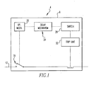
- the circuit breaker 4 includes a housing 8 that carries a conductor 12 which passes current through the circuit breaker 4, a set of separable contacts 16 interposed within the conductor 12 to selectively interrupt the flow of current therethrough, and an operating mechanism 20 that operates the contacts 16.
- the circuit breaker 4 advantageously additionally includes a delay mechanism 24 that inertially delays the actuation of a switch 28 in order to provide a time delayed input to a trip unit 32 that the circuit breaker 4 has been switched between an OFF condition, such as is depicted generally in Figs. 2 and 4 and an ON condition depicted generally in Figs. 1 and 8.
- the trip unit 32 includes self-powered electronics, meaning that trip unit 32 does not possess an auxiliary or external source of power for the electronics thereof apart from the current that flows through the conductor 12 when the circuit breaker 4 is in the ON condition. It is understood, however, that the teachings of the present invention can be employed in a circuit breaker even if the trip unit additionally includes an auxiliary power source.
- the delay mechanism 24 advantageously permits the trip unit 32 to become fully operational after switching the circuit breaker 4 to the ON condition prior to a signal indicating a change in state of the circuit breaker 4 being sent from the switch 28 to the trip unit 32.
- Fig. 2 generally depicts a panel 34 of the housing 8 and additionally depicts a lay shaft 36 of the operating mechanism 20 disposed thereon.
- the operating mechanism 20 additionally includes a movable member which, in the exemplary depicted embodiment, is in the form of a crank 40 affixed to the lay shaft 36.
- the crank 40 is pivotably movable by pivoting of the lay shaft 36 about a shaft axis 44 when the circuit breaker is switched between the OFF and ON conditions.
- the crank 40 includes an elongated slot 48 formed therein that is cooperable with a part of the delay mechanism 24, as will be described below.
- the conductor 12 the separable contacts 16, the operating mechanism 20, the delay mechanism 24, the switch 28, and the trip unit 32 are disposed on the housing 8.
- the housing 8 additionally includes a mounting plate 52 mounted to the panel 34.
- the delay mechanism 24 is generally mounted on the mounting plate 52.
- the delay mechanism 24 includes an inertia member 56, a first spring 60, a second spring 64, and a pivot 68.
- the pivot 68 is affixed to the mounting plate 52.
- the inertia member 56 is pivotably mounted on the pivot 68 and is pivotable about a pivot axis 72 provided by the pivot 68.
- the pivot axis 72 and the shaft axis 44 are parallel with one another and spaced apart.
- the inertia member 56 includes a central member 76, an extension portion 86 extending from the central member 76, and a foot 84 likewise extending from the central member 76 but in a different direction.
- the inertia member 56 is a monolithically formed single piece member that may be formed of a material such as injection-molded plastic, although other configurations and materials are possible.
- the inertia member 56 is pivotable on the pivot 68 between an initial position, i.e., Fig. 4, that corresponds with the OFF condition of the circuit breaker 4, and a terminal position, i.e. , Fig. 8, that corresponds with the ON condition of the circuit breaker 4.
- the extension portion 80 of the inertia member 56 includes an arcuate lateral surface 88 that terminates at an indentation 92. The lateral surface 88 is engaged with the switch 28 to retain the switch in a first condition, i.e.
- the lateral surface 88 is substantially at a fixed radius from the pivot 68.
- Movement of the switch 28 from the first condition to the second condition provides a signal to the trip unit 32 indicating a change in state of the circuit breaker 4.
- the pivoting movement of the inertia member 56 from the initial position, i.e. , Figs. 4 and 5, to the terminal position, i.e. , Fig. 8, provides a time delay in accordance with the present invention, as will be described in greater detail below.
- the extension portion 80 additionally includes a bearing surface 96 that is cooperable with the second spring 64 in a fashion described below.
- the foot 84 includes a boss 100 extending therefrom that is cooperable with a pin 104 to connect with an end of the first spring 60.
- An opposite end of the first spring 60 is connected with a post 108 which carries a clip 112.
- the post 108 is affixed to the mounting plate 52.
- the first spring 60 thus can generally be said to extend between the inertia member 56 and the housing 8.
- the first spring 60 biases the inertial member 56 from the initial position, i.e. , Figs. 4 and 5, toward the terminal position, i.e. , Fig. 8.
- the first spring 60 is a tension coil spring.
- the second spring 64 is depicted in the exemplary embodiment as being a torsion spring having a body 116, a first leg 120, and a second leg 124.
- the body 116 extends about the central member 76 of the inertia member 56, and thus likewise extends about the pivot 68 and the pivot axis 72.
- the first leg 120 is slidably received in the slot 48 of the crank 40.
- the second leg 124 is receivable against the bearing surface 96 of the extension portion 80.
- the switch 28 is affixed to the mounting plate 52 with a number of fasteners 128 which are depicted in the exemplary embodiment as being screws with nuts.
- the lay shaft 36 and the crank 40 are movable between the first position which corresponds with the OFF condition of the circuit breaker 4 and is depicted in Fig. 4, and a second position that corresponds with the ON condition of the circuit breaker 4 and is depicted generally in Figs. 7 and 8.
- the lay shaft 36 is in the first position, the second leg 124 is received against the bearing surface 96, and the second spring 64 biases the inertia member 56 toward the initial position.
- the bias of the second spring 64 overcomes the bias of the first spring 60 and retains the inertia member 56 in the initial position.
- the lay shaft 36 passes through an intermediate position, i.e. , Fig. 5, in moving from the first position of Fig. 4 to the second position of Figs. 7 and 8. Moreover, since the first leg 120 of the second spring 64 is received in the slot 48 and thus moves with the lay shaft 36, the bias of the second spring 64 decreases as the lay shaft 36 moves from the first position of Fig. 4 toward the intermediate position of Fig. 5. When the lay shaft 36 reaches the intermediate position of Fig.
- the bias of the second spring 64 which biases the inertia member 56 toward the initial position has decreased to the point that it is equal to the bias of the first spring 60 that biases the inertia member 56 from the initial position toward the terminal position.
- the inertia member 56 is retained in a state of equipoise at the initial position between the bias of the first spring 60 and the reduced bias of the second spring 64. It thus can be seen that while the lay shaft 36 has pivoted from the first position of Fig. 4 to the intermediate position of Fig. 5, the inertia member 56 has remained stationery at the initial position.
- the lateral surface 88 of the inertia member 56 remains slidably engaged with the switch 28 until the inertia member 56 has pivoted generally to the terminal position, at which point the switch 28 is permitted to switch from the first condition to the second condition due to the proximity of the indentation 92.
- An advantage of the delay mechanism 24 having both the first and the second springs 60 and 64 is that a relatively large time delay can be provided without providing the inertia member 56 with a substantial mass or polar moment of inertia. Rather, the time delay provided by the inertia member 56 comes about, at least in part, by the interaction of the first and second springs 60 and 64 acting on the relatively small inertia member 56.
- the inertia member 56 does not even begin to move from the initial position until after the lay shaft 36 has moved past the intermediate position of Fig. 5.
- the foot 84 engages the lay shaft 36 to stop the pivoting motion of the inertia member 56. Relatively little stopping effect is required by the foot 84 to stop the inertia member 56 since the delay mechanism 24 is advantageously configured with both the first and second springs 60 and 64 and the relatively lightweight inertia member 56. In this regard, it is understood that the inertia member 56 moves with relatively low speeds and energies. Such reduced speeds and energies contribute to the longevity of the delay mechanism 24 and the reliability thereof.
- the biasing forces of the first and second springs 60 and 64 are substantially at their maximum levels when the circuit breaker 4 is in the OFF condition of Fig. 4. Also, the body 116 of the second spring 64 pivots about the pivot axis 72 and thus about the pivot 68 between a first orientation, such as is depicted generally in Fig. 4, and a second orientation, such as is depicted generally in Fig. 8, when the circuit breaker 4 moves between the OFF and ON conditions.
Landscapes
- Breakers (AREA)
- Driving Mechanisms And Operating Circuits Of Arc-Extinguishing High-Tension Switches (AREA)
Abstract
Description
Claims (13)
- A circuit breaker movable between an OFF condition and an ON condition, the circuit breaker comprising:a housing;a set of separable contacts disposed on the housing;an operating mechanism that is disposed on the housing and is operable to move the contacts between a disconnected position and a connected position when activated, the operating mechanism including a movable structure that is movably disposed on the housing and is movable between a first position corresponding with the OFF condition of the circuit breaker and a second position corresponding with the ON condition of the circuit breaker;a trip unit that is responsive to current through the separable contacts for activating the operating mechanism;a switch for providing an input to the trip unit, the switch being switchable between a first condition corresponding with the OFF condition and a second condition that corresponds with the ON condition;a delay mechanism for delaying movement of the switch from the first condition to the second condition for a given period of time after a circuit breaker has moved from the OFF condition to the ON condition;the delay mechanism including an inertia member, a first spring, and a second spring;the inertia member being movable between an initial position corresponding with the OFF condition of the circuit breaker and a terminal position corresponding with the ON condition of the circuit breaker, the inertia member in the initial position maintaining the switch in the first condition, the inertia member in the terminal position permitting movement of the switch to the second condition;the first spring extending between the inertia member and the housing and biasing the inertia member toward the terminal position;the second spring extending between the movable structure and the inertia member when the movable structure is in the first position, the second spring biasing the inertia member toward the initial position and overcoming the bias of the first spring to retain the inertia member in the initial position when the movable structure is in the first position;the bias of the first and second springs being equal and retaining the inertia member in a state of equipoise at the initial position when the movable structure is in an intermediate position between the first and second positions; andthe bias of the first spring overcoming any bias of the second spring and biasing the inertia member toward the terminal position when the movable structure is in substantially any of the second position and a location disposed between the intermediate and second positions.
- The circuit breaker of Claim 1 wherein
the second spring extends between the movable structure and the inertia member and overcomes the bias of the first spring to retain the inertia member in the initial position when the movable structure is in any of the first position and a location disposed between the intermediate and first positions. - The circuit breaker of Claim 1 wherein
the inertia member is pivotably movable about a pivot between the initial and terminal positions. - The circuit breaker of Claim 3 wherein
the movable member is a crank affixed to a shaft that pivots the crank about a shaft axis between the first and second positions. - The circuit breaker of Claim 4 wherein
the second spring is a torsion spring having a body, a first leg, and a second leg, the body extending about the pivot, the first leg being engageable with the crank, the second leg being engageable with the inertia member. - The circuit breaker of Claim 5 wherein
the pivot provides a pivot axis for the inertia member, the pivot axis being parallel with and spaced from the shaft axis. - The circuit breaker of Claim 6 wherein
the crank includes a slot formed therein, the first leg being slidably disposed in the slot. - The circuit breaker of Claim 5 wherein
the body of the second spring pivots about the pivot between a first orientation and a second orientation when the circuit breaker moves between the OFF and ON conditions. - The circuit breaker of Claim 4 wherein
the inertia member includes a foot that is engaged with the shaft when the inertia member is in the terminal position. - The circuit breaker of Claim 1 wherein
the inertia member includes a lateral surface that is slidably engageable with the switch to retain the switch in the first condition when the inertia member is in the initial position. - The circuit breaker of Claim 10 wherein
the lateral surface is disengaged from the switch to permit the switch to move to the second condition when the inertia member is in the terminal position. - The circuit breaker of Claim 10 wherein
the inertia member is pivotably movable about a pivot between the initial and terminal positions; and
the lateral surface being of a substantially fixed radius from the pivot. - The circuit breaker of Claim 1 wherein
the biasing forces of the first and second springs are substantially at a maximum when the circuit breaker is in the OFF condition.
Applications Claiming Priority (2)
| Application Number | Priority Date | Filing Date | Title |
|---|---|---|---|
| US10/848,801 US6864450B1 (en) | 2004-05-19 | 2004-05-19 | Circuit breaker with delay mechanism |
| US848801 | 2004-05-19 |
Publications (2)
| Publication Number | Publication Date |
|---|---|
| EP1600994A1 true EP1600994A1 (en) | 2005-11-30 |
| EP1600994B1 EP1600994B1 (en) | 2007-06-20 |
Family
ID=34218289
Family Applications (1)
| Application Number | Title | Priority Date | Filing Date |
|---|---|---|---|
| EP05010757A Expired - Lifetime EP1600994B1 (en) | 2004-05-19 | 2005-05-18 | Circuit breaker with delay mechanism |
Country Status (4)
| Country | Link |
|---|---|
| US (1) | US6864450B1 (en) |
| EP (1) | EP1600994B1 (en) |
| CN (1) | CN1700385A (en) |
| DE (1) | DE602005001421T2 (en) |
Cited By (1)
| Publication number | Priority date | Publication date | Assignee | Title |
|---|---|---|---|---|
| DE102007003175B4 (en) * | 2007-01-22 | 2014-11-27 | Siemens Aktiengesellschaft | Selective circuit breaker |
Families Citing this family (14)
| Publication number | Priority date | Publication date | Assignee | Title |
|---|---|---|---|---|
| DE102006037225A1 (en) * | 2006-08-09 | 2008-02-14 | Siemens Ag | Switching unit |
| US20080122563A1 (en) * | 2006-08-28 | 2008-05-29 | Ls Industrial Systems Co., Ltd. | Instantaneous trip mechanism for mould cased circuit breaker |
| ES2311368B2 (en) * | 2006-09-06 | 2010-05-05 | Ls Industrial Systems Co, Ltd | INSTANTANEOUS SHOOTING MECHANISM FOR MOLDED MOLDED DISKLINDER. |
| US7557682B2 (en) * | 2006-12-01 | 2009-07-07 | Eaton Corporation | Inertial solenoid delay for the opening of medium voltage circuit breakers |
| US7696447B2 (en) * | 2007-06-01 | 2010-04-13 | Eaton Corporation | Electrical switching apparatus and stored energy assembly therefor |
| US7598468B2 (en) * | 2007-06-01 | 2009-10-06 | Eaton Corporation | Electrical switching apparatus, and stored energy assembly and time delay mechanism therefor |
| US7696448B2 (en) * | 2007-06-08 | 2010-04-13 | Eaton Corporation | Closing protection mechanism for a closing assembly over-toggle linkage |
| KR100876412B1 (en) * | 2007-07-12 | 2008-12-31 | 엘에스산전 주식회사 | Breaker delay time output device |
| EP2249366B1 (en) * | 2009-05-06 | 2013-09-04 | ABB Technology AG | Signalling device for circuit breaker and electrical apparatus comprising the signalling device |
| EP2669923B1 (en) * | 2012-06-01 | 2015-09-02 | General Electric Company | Circuit breaker and method of tripping a circuit breaker |
| KR101759601B1 (en) | 2015-12-28 | 2017-07-31 | 엘에스산전 주식회사 | Delay time generation apparatus for air circuit breaker |
| CN105513916B (en) * | 2016-01-21 | 2018-06-29 | 首瑞(天津)电气设备有限公司 | Deferred action mechanism and breaker in breaker |
| KR101869724B1 (en) | 2017-01-05 | 2018-06-21 | 엘에스산전 주식회사 | Magnetic trip device for circuit breaker |
| KR102299858B1 (en) * | 2017-03-15 | 2021-09-08 | 엘에스일렉트릭 (주) | Magnetic trip mechanism for circuit breaker |
Citations (3)
| Publication number | Priority date | Publication date | Assignee | Title |
|---|---|---|---|---|
| FR2516299A1 (en) * | 1981-11-09 | 1983-05-13 | Telemecanique Electrique | Delayed operation magnetically operated overcurrent relay - uses cylindrical inertia wheel to slow passage of operating arm when overcurrent occurs |
| EP0523420A2 (en) * | 1991-07-13 | 1993-01-20 | Licentia Patent-Verwaltungs-GmbH | Short-circuit instantaneous trip mechanism |
| US6377431B1 (en) * | 1999-08-13 | 2002-04-23 | Eaton Corporation | Non-automatic power circuit breaker including trip mechanism which is disabled after closure of separable contacts |
Family Cites Families (10)
| Publication number | Priority date | Publication date | Assignee | Title |
|---|---|---|---|---|
| DE2219892C3 (en) * | 1972-04-19 | 1975-10-16 | Siemens Ag, 1000 Berlin Und 8000 Muenchen | Electrical circuit breaker with a switch lock |
| US4181829A (en) * | 1978-04-12 | 1980-01-01 | Allen-Bradley Company | Time delay switch actuating mechanism |
| US4697163A (en) * | 1986-03-27 | 1987-09-29 | Westinghouse Electric Corp. | Circuit breaker with impact trip delay |
| US4933519A (en) | 1988-08-31 | 1990-06-12 | Westinghouse Electric Corp. | Contact structure for grounding switch |
| US5142112A (en) * | 1990-04-03 | 1992-08-25 | Westinghouse Electric Corp. | Circuit breaker positive off interlock |
| US5089797A (en) * | 1990-11-14 | 1992-02-18 | Westinghouse Electric Corp. | Circuit breaker with dual function electromagnetic tripping mechanism |
| US5898146A (en) * | 1997-09-18 | 1999-04-27 | Eaton Corporation | Molded case circuit breaker with modular crossbar |
| US5875088A (en) | 1998-02-17 | 1999-02-23 | Eaton Corporation | Electrical switching apparatus employing interlocks for first and second trip functions |
| US6175479B1 (en) | 1999-04-15 | 2001-01-16 | Siemens Energy & Automation, Inc. | Instantaneous protection device and method for a circuit breaker |
| US6738243B2 (en) | 2001-12-07 | 2004-05-18 | Eaton Corporation | Apparatus and method for servicing a distribution bus |
-
2004
- 2004-05-19 US US10/848,801 patent/US6864450B1/en not_active Expired - Fee Related
-
2005
- 2005-05-18 DE DE602005001421T patent/DE602005001421T2/en not_active Expired - Fee Related
- 2005-05-18 EP EP05010757A patent/EP1600994B1/en not_active Expired - Lifetime
- 2005-05-19 CN CNA2005100708285A patent/CN1700385A/en active Pending
Patent Citations (3)
| Publication number | Priority date | Publication date | Assignee | Title |
|---|---|---|---|---|
| FR2516299A1 (en) * | 1981-11-09 | 1983-05-13 | Telemecanique Electrique | Delayed operation magnetically operated overcurrent relay - uses cylindrical inertia wheel to slow passage of operating arm when overcurrent occurs |
| EP0523420A2 (en) * | 1991-07-13 | 1993-01-20 | Licentia Patent-Verwaltungs-GmbH | Short-circuit instantaneous trip mechanism |
| US6377431B1 (en) * | 1999-08-13 | 2002-04-23 | Eaton Corporation | Non-automatic power circuit breaker including trip mechanism which is disabled after closure of separable contacts |
Cited By (1)
| Publication number | Priority date | Publication date | Assignee | Title |
|---|---|---|---|---|
| DE102007003175B4 (en) * | 2007-01-22 | 2014-11-27 | Siemens Aktiengesellschaft | Selective circuit breaker |
Also Published As
| Publication number | Publication date |
|---|---|
| CN1700385A (en) | 2005-11-23 |
| DE602005001421D1 (en) | 2007-08-02 |
| DE602005001421T2 (en) | 2008-02-21 |
| US6864450B1 (en) | 2005-03-08 |
| EP1600994B1 (en) | 2007-06-20 |
Similar Documents
| Publication | Publication Date | Title |
|---|---|---|
| US6864450B1 (en) | Circuit breaker with delay mechanism | |
| US6218920B1 (en) | Circuit breaker with adjustable magnetic trip unit | |
| US7570146B2 (en) | Circuit breaker including ambient compensation bimetal holding and releasing arc fault indicator | |
| CA2704408C (en) | Inertial catch for an automatic transfer switch power contactor | |
| US7843291B2 (en) | Integrated maglatch accessory | |
| EP1939912A1 (en) | Activation for switching apparatus | |
| US7532096B2 (en) | Auxiliary switch including movable slider member and electric power apparatus employing same | |
| EP0766280A2 (en) | Control and signal device for a protection circuit breaker | |
| CN101345168A (en) | Time delay output apparatus for circuit breaker | |
| KR100652236B1 (en) | Forward seating device of circuit breaker | |
| EP0984476A2 (en) | Trip device of circuit breaker | |
| US6476337B2 (en) | Auxiliary switch actuation arrangement | |
| US6507256B1 (en) | Auxiliary magnetic trip system | |
| US5036303A (en) | Bell alarm accessory arrangement for molded case circuit interrupter | |
| US6727788B1 (en) | Latch mechanism for a circuit breaker | |
| CA2588397A1 (en) | Crossbar assist mechanism and electrical switching apparatus employing the same | |
| US6917267B2 (en) | Non-conductive barrier for separating a circuit breaker trip spring and cradle | |
| ES2566102T3 (en) | Insufficient voltage tripping device of molded case circuit breaker | |
| US6545584B2 (en) | Circuit breaker with inertia device to prevent shockout | |
| EP3319102B1 (en) | Indication device of electric switch | |
| JP2003346638A (en) | Circuit breaker | |
| US5027092A (en) | Tripping arrangement for molded case circuit interrupter | |
| US3495198A (en) | Electric circuit breaker with releasable coupling mechanism | |
| US7064634B1 (en) | Shock resistant actuators for a circuit breaker | |
| US5043688A (en) | Actuator-accessory interface unit for molded case circuit interrupter |
Legal Events
| Date | Code | Title | Description |
|---|---|---|---|
| PUAI | Public reference made under article 153(3) epc to a published international application that has entered the european phase |
Free format text: ORIGINAL CODE: 0009012 |
|
| AK | Designated contracting states |
Kind code of ref document: A1 Designated state(s): AT BE BG CH CY CZ DE DK EE ES FI FR GB GR HU IE IS IT LI LT LU MC NL PL PT RO SE SI SK TR |
|
| AX | Request for extension of the european patent |
Extension state: AL BA HR LV MK YU |
|
| RIN1 | Information on inventor provided before grant (corrected) |
Inventor name: KREVOKUCH, ROBERT N. Inventor name: RICCIUTI, ANTHONY T. Inventor name: BOTTEGAL, PAUL T. Inventor name: PALMIERI, DANIEL E. Inventor name: CHEN, STEVEN Z. |
|
| 17P | Request for examination filed |
Effective date: 20060328 |
|
| AKX | Designation fees paid |
Designated state(s): DE FR |
|
| GRAP | Despatch of communication of intention to grant a patent |
Free format text: ORIGINAL CODE: EPIDOSNIGR1 |
|
| GRAS | Grant fee paid |
Free format text: ORIGINAL CODE: EPIDOSNIGR3 |
|
| GRAA | (expected) grant |
Free format text: ORIGINAL CODE: 0009210 |
|
| AK | Designated contracting states |
Kind code of ref document: B1 Designated state(s): DE FR |
|
| REF | Corresponds to: |
Ref document number: 602005001421 Country of ref document: DE Date of ref document: 20070802 Kind code of ref document: P |
|
| ET | Fr: translation filed | ||
| PLBE | No opposition filed within time limit |
Free format text: ORIGINAL CODE: 0009261 |
|
| STAA | Information on the status of an ep patent application or granted ep patent |
Free format text: STATUS: NO OPPOSITION FILED WITHIN TIME LIMIT |
|
| 26N | No opposition filed |
Effective date: 20080325 |
|
| REG | Reference to a national code |
Ref country code: FR Ref legal event code: ST Effective date: 20090119 |
|
| PG25 | Lapsed in a contracting state [announced via postgrant information from national office to epo] |
Ref country code: FR Free format text: LAPSE BECAUSE OF NON-PAYMENT OF DUE FEES Effective date: 20080602 Ref country code: DE Free format text: LAPSE BECAUSE OF NON-PAYMENT OF DUE FEES Effective date: 20081202 |