EP1600763A2 - Defect detection device and bag packaging system equipped with defect detection device - Google Patents
Defect detection device and bag packaging system equipped with defect detection device Download PDFInfo
- Publication number
- EP1600763A2 EP1600763A2 EP05011129A EP05011129A EP1600763A2 EP 1600763 A2 EP1600763 A2 EP 1600763A2 EP 05011129 A EP05011129 A EP 05011129A EP 05011129 A EP05011129 A EP 05011129A EP 1600763 A2 EP1600763 A2 EP 1600763A2
- Authority
- EP
- European Patent Office
- Prior art keywords
- bags
- bag
- transfer unit
- detection device
- defect detection
- Prior art date
- Legal status (The legal status is an assumption and is not a legal conclusion. Google has not performed a legal analysis and makes no representation as to the accuracy of the status listed.)
- Granted
Links
Images



Classifications
-
- G—PHYSICS
- G01—MEASURING; TESTING
- G01N—INVESTIGATING OR ANALYSING MATERIALS BY DETERMINING THEIR CHEMICAL OR PHYSICAL PROPERTIES
- G01N21/00—Investigating or analysing materials by the use of optical means, i.e. using sub-millimetre waves, infrared, visible or ultraviolet light
- G01N21/84—Systems specially adapted for particular applications
- G01N21/88—Investigating the presence of flaws or contamination
- G01N21/89—Investigating the presence of flaws or contamination in moving material, e.g. running paper or textiles
Definitions
- the present invention relates to a defect detection device and a bag packaging system equipped with the defect detection device. More specifically, the present invention relates to a defect detection device that is arranged downstream of a bag packaging machine and determines defects of bags while receiving and conveying the bags manufactured by the bag packaging machine.
- bag packaging machines that manufacture bags automatically by thermally sealing a portion of sheet-like package and enclose contents such as snack foods in such bags in order to make bag products.
- Japanese Patent Application Publication No. 2002-037206 discloses a longitudinal bag packaging machine that can control the interval and the posture at which and in which the bags are discharged after they are manufactured by and transferred from the bag packaging machine.
- This longitudinal bag packaging machine is provided with a transport conveyor that conveys the manufactured bags to post-processing devices. By controlling the drive of the transport conveyor, the longitudinal bag packaging machine controls the discharge interval and the discharge posture of the bags that are conveyed.
- This configuration enables prevention of defect formation in post-processing devices such as a seal checker and a weight checker, while the discharge interval and the discharge posture tend to be compromised where a stationary chute is used instead of a transfer conveyor, particularly when a larger number of bags are discharged at a high processing speed.
- the longitudinal bag packaging machine disclosed in the Japanese Patent Application Publication No. 2002-037206 simply controls the conveying speed of the transport conveyor in order to control disturbance in the interval and the posture of the bags that are discharged consecutively from the bag packaging machine. Therefore, defective bags caused by sealing failure cannot be detected. Consequently, the defective bags cannot be found at an early point to be removed from the conveyance path, and it is far from an effective process.
- the object of the present invention is to provide a defect detection device, which enables an effective process by promptly detecting defects of bags after the bags are manufactured by the bag packaging machine.
- the object of the present invention is also to provide a bag packaging system having such defect detection device.
- the defect detection device is a defect detection device that is adapted to receive bags manufactured by a bag packaging machine and convey the bags to a downstream side through a conveyance path while checking for defects of the bags.
- the defect detection device includes a first transfer unit, a detector, and a controller.
- the first transfer unit is arranged below the bag packaging machine and adapted to receive the bags that are discharged from the bag packaging machine and convey the bags to a downstream side.
- the detector is arranged adjacent to a downstream end of the first transfer unit and configured to send a detection signal when the detector detects an object that is conveyed by the first transfer unit.
- the controller is operatively connected to the first transfer unit and the detector, and stores therein a size of a proper bag that is being manufactured.
- the controller is configured to find a defective bag based on the size of the proper bag, a conveying speed of the first transfer unit, and duration of the detection signal from the detector.
- the detector at the downstream end of the first transfer unit below the bag packaging machine detects objects such as the bags and their contents that are discharged and conveyed from the bag packaging machine, and the controller determines whether there is any defective bag.
- the bag packaging machine manufactures the bags that contain food products such as potato chips that have oil content
- the oil tends to soil the conveyance path that extends from the first transfer unit to the downstream side. Therefore, removal of such contents from the conveyance path at an early point, as in the case for the defect detection device of the present invention, can prevent slipping and tipping of the bags and pitch misalignment of the bags during conveyance. This is especially effective when the conveyance path is tilted upward, in which the bags are conveyed upward from upstream side of the first transfer unit to the downstream side, since the bags easily slip on such tilted conveyance path because when the conveyance path is soiled with oil.
- the defects of the bags described here include a case where contents of a bag are discharged onto the first transfer unit with a sealing failure, and a case where bags that should be conveyed at predetermined intervals after being manufactured by the bag packaging machine are conveyed one after another at an interval that is too narrow and thus the bags cannot be processed properly by the downstream post-processing devices.
- the defects further include a case where a double-bag (a bag having a length of two bags) is manufactured due to the reaction of a metal detector that is provided between a weighing machine and a packaging machine of the bag packaging machine, and a case where a bag having other irregular length and irregular size is manufactured due to a setting error.
- a conveyor or a chute can be used as the first transfer unit. Specifically, when a conveyor is used as the first transfer unit, it results in an accurate control of the conveying speed. Thus, defect determination by the controller can be implemented more accurately.
- the defect detection device is the defect detection device of the first aspect of the present invention, wherein the detector is arranged so as to be partially below and partially above a conveyance surface of the first transfer unit.
- the detector that detects objects that are conveyed on the first transfer unit is arranged so as to also cover the space below and above the conveyance surface of the first transfer unit, the detector can detect not only a relatively large bag but also contents of a bag that are spilled onto the conveyance surface of the first transfer unit due to a sealing failure.
- the defect detection device is the defect detection device of the first or the second aspect of the present invention, further including a second transfer unit that is arranged on the downstream side of the first transfer unit.
- the defect detection device further includes the second transfer unit that is connected with the first transfer unit and is arranged on the downstream side of the first transfer unit, which is disposed below the bag packaging machine.
- This configuration enables a smooth conveyance of the bags to the post-processing devices, which are arranged further downstream of the defect detection device.
- the defect detection device is the defect detection device of the third aspect of the present invention, wherein the downstream end of the first transfer unit is arranged so as to be above an upstream end of the second transfer unit.
- the position of the downstream end of the first transfer unit at the connecting portion between the first and the second transfer units is determined in relation to the position of the upstream end of the second transfer unit, which is arranged on the downstream side of the first transfer unit.
- the downstream end of the first transfer unit is arranged so as to be above the upstream end of the second transfer unit at the connecting portion between the first and the second transfer units, thereby creating a step portion between the first and the second transfer units.
- This configuration enables the detector to be easily arranged below the imaginary surface that is formed by extending the conveyance surface of the first transfer unit.
- the defect detection device is the defect detection device of any of the first through the fourth aspects of the present invention, wherein the detector is a line sensorthat has a plurality of projectors and a plurality of photoreceivers.
- the plurality of projectors and a plurality of photoreceivers are arranged such that the object conveyed by the first transfer unit passes between the plurality of projectors and the plurality of photoreceivers.
- the duration of time during which the amount of light received by the photoreceiver has decreased is long compared to the proper interval time period which is calculated based on the conveying speed of the first transfer unit and the size of the proper bag, defects such as overlapping or unsevered bags will be detected as the bags are conveyed. Therefore, the defective bags that are conveyed by the first transfer unit are detected with an inexpensive and simple composition.
- the defect detection device is the defect detection device according to one of the first through the fifth aspects of the present invention, wherein the first transfer unit has a conveying belt that conveys the object and a motor that rotates the conveying belt.
- the conveying speed can be easily controlled. Additionally, since objects can be conveyed at a more accurate conveying speed as compared to a case where a chute is used as the first transfer unit, a calculation for detection of defects by the controller can be implemented more accurately.
- the defect detection device is defect detection device according to one of the first through the sixth aspects of the present invention, wherein the first transfer unit is pivotably supported by the second transfer unit.
- the first transfer unit can be pivoted around, for example, the vicinity of the downstream end of the first transfer unit, so as to better accommodate the size (length) of the bags manufactured by the bag packaging machine.
- This configuration enables the upstream end of the first transfer unit to be lowered to an appropriate height when the bags being manufactured are big, while also enabling the upstream end to be raised to an appropriate height when the bags being manufactured are small. Consequently, even when different types of bags are manufactured, the bags can be conveyed smoothly to the defect detection device and to the post-processing devices downstream.
- the first transfer unit can pivot around, for example, the vicinity of the downstream end of the first transfer unit, the height of the first transfer unit can be changed without making a substantial change to the positional relationship between the detector that is adjacent to the downstream end of the first transfer unit and the downstream end of the first transfer unit. Consequently, even when the height of the first transfer unit is changed, defects can be detected by the detector in a stable manner.
- the defect detection device is the defect detection device of the third or the fourth aspect of the present invention, wherein the controller is configured to find a defective bag further based on a conveying speed of the second transfer unit.
- the controller that determines whether or not detected bags are defective also takes into consideration the conveying speed of the second transfer unit that is arranged downstream of the first transfer unit.
- a front portion of the bag in the conveying direction may be already reaching the second transfer unit and conveyed by the second transfer unit while the bag is being detected by the detector. Therefore, when the size (length) of a bag is long, more accurate defect determination can be achieve by taking into account the conveying speed of the second transfer unit and the duration of the detection signal from the detector.
- the defect detection device is the defect detection device according to any of the first through the eighth aspects of the present invention, further including a remover that removes object from the conveyance path when the controller finds a defective bag.
- the defect detection device further includes the remover that removes the bags determined to be defective by the controller and the contents that spilled onto the conveyance path from the conveying surface of the first transfer unit.
- This configuration enables removal of the defective bags and the contents spilled onto the conveying surface due to a sealing failure before such bags and contents are conveyed to the post-processing devices arranged on the downstream side of the defect detection device. By removing the defective bags before they go through the post-processes, unnecessary processes can be avoided, thereby improving the process efficiency.
- the defect detection device is the defect detection device of the ninth aspect of the present invention, wherein the remover is adapted to remove the object from the conveyance path by blowing air onto the object.
- a device such as an air jet that blows air onto an object is utilized as the remover to remove from the conveyance path the defective bags and the contents that spilled onto the conveyance path.
- This configuration enables the defective bags and the contents that spilled onto the conveyance path due to sealing failure to be removed from the conveyance path in a reliable manner with an inexpensive composition.
- the defect detection device is the defect detection device of the ninth or tenth aspect of the present invention, further including a second transfer unit that is arranged on the downstream side of the first transfer unit, and in which the remover is adapted to remove the object from the conveyance path while the object is being conveyed by the second transfer unit.
- the defect detection device is the defect detection device of the seventh aspect of the present invention, in which the first transfer unit is supported to the second transfer unit so as to be pivotable around the downstream end of the first transfer unit.
- the defect detection device is the defect detection device of any of the first though the twelfth aspects of the present invention, in which the controller is configured to calculate a proper detection time range based on the size of the proper bag and the conveying speed of the first transfer unit, and the controller is configured to find a defective bag when the duration of the detection signal is either longer or shorter than the proper detection time range.
- the defect detection device is the defect detection device of any of the first though the thirteenth aspects of the present invention, in which the controller is configured to calculate a proper interval time period based on the size of the proper bag and the conveying speed of the first transfer unit, and the controller is configured to find a defective bag when an interval between the detection signals is shorter than the proper interval time period.
- the bag packaging system includes a bag packaging machine that manufactures bags by sealing a sheet-like package paper and forming bags with contents contained therein, and the defect detection device according to any of the first through fourteenth aspects of the present invention that is designed to receive bags manufactured by the bag packaging machine and convey the bags to a downstream side through a conveyance path while checking for defects of the bags.
- the detector at the downstream end of the first transfer unit that is disposed below the bag packaging machine detects the bags and their spilled contents discharged that are conveyed from the bag packaging machine, so that the controller can find defects.
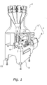
- Figure 1 is a perspective view of a bag packaging system in accordance with an embodiment of the present invention
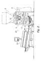
- FIG. 2 is a side view of the bag packaging system in accordance with the embodiment of the present invention.
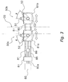
- Figure 3 is a side view of a transverse sealing mechanism of the bag packaging system in accordance with the embodiment of the present invention.
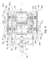
- Figure 4 is a plan view of the transverse sealing mechanism of the bag packaging system illustrated in Figure 3 in accordance with the embodiment of the present invention
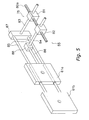
- Figure 5 is an explanatory partial view of a sideway drive mechanism of the bag packaging system in accordance with the embodiment of the present invention.
- Figure 6 is a side view of a defect detector included of the bag packaging system in accordance with the embodiment of the present invention.
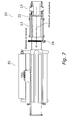
- Figure 7 is a plan view of the defect detector of the bag packaging system illustrated in Figure 6 in accordance with the embodiment of the present invention.
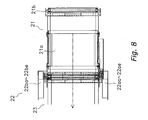
- Figure 8 is an enlarged plan view of the connecting portion between the conveyor belts of the defect detector of the bag packaging system illustrated in Figure 6 in accordance with the embodiment of the present invention
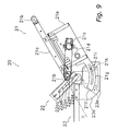
- Figure 9 is a side view of the defect detector of the bag packaging system illustrated in Figure 6 in accordance with the embodiment of the present invention.
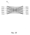
- Figure 10 is an explanatory view of the photoreceivers and projectors of the line sensor of the bag packaging system in accordance with the embodiment of the present invention.
- FIG 11 is a control block diagram of the bag packaging system illustrated in Figure 1 in accordance with the embodiment of the present invention.
- Figures 12A-E are schematic diagrams of the detection signals to be transmitted from the line sensor to a controller of the bag packaging system in accordance with the embodiment of the present invention.
- a bag packaging system 1 provided with the defect detection device according to an embodiment of the present invention will be now described with reference to Figures 1 to 12.
- the bag packaging system 1 is a machine that packages such contents as potato chips, and mainly includes a bag packager (bag packaging machine) 5 that serves as the main section where the contents to be packaged are put into bags, a film feeder 6 that feeds film to the bag packager 5 for making the bags, and a defect detector (an example of the defect detection device) 20 that detects the defective bags while conveying the bags manufactured by the bag packager 5 to post-processing devices such as a seal checker 30 in the subsequent process.
- An operating switch 7 is arranged on the front panel of the bag packager 5.
- a liquid crystal display 8 that indicates the operating state is arranged in a position where it can be viewed by an operator operating the operating switch 7.
- the film feeder 6 serves to feed sheet-like film to a forming mechanism 13 of the bag packager 5 and, in this embodiment, is provided adjacent to the bag packager 5.
- a roll of film is set in the film feeder 6 and the film is discharged from the roll.
- the bag packager 5 includes a forming mechanism 13 that forms the film (which is fed in sheet form) into a tubular form, a pull-down belt mechanism (packaging material conveying mechanism) 14 that conveys the tubular-formed film (hereinafter called “tubular film”) downward, a longitudinal sealing mechanism 15 that longitudinally heat-seals an overlapping section of the tubular film, a transverse sealing mechanism 17 that transversely seals the tubular film so as to close the top and bottom ends of the bag, and a support frame 12 that supports these mechanisms.
- a casing 9 is installed around the support frame 12.
- the forming mechanism 13 has a tube 31 and a former 32.
- the tube 31 is a cylindrical member that is open at its upper and lower ends. In a plan view, the tube 31 is arranged in an open portion near the center of a ceiling plate 29 and is integrally joined with the former 32 by a bracket not shown in the figures.
- a combination weighing machine 2 weighs a predetermined quantity of contents and supplies the predetermined quantity of contents to be packaged into the upper opening of the tube 31.
- the former 32 is arranged so as to surround the tube 31.
- the former 32 is shaped such that the sheet-like film F fed from the film feeder 6 is formed into a tubular form as it passes between the former 32 and the tube 31.
- the former 32 is fixedly supported to the support frame 12 by a support member not shown in the figures.
- the tube 31 and former 32 of the forming mechanism 13 are constituted such that they can be exchanged with other tubes and formers depending on the width of the bags being made. Consequently, the forming mechanism 13 are disposed within the support frame 12 so as to be freely attached to and detached from the support frame 12.
- the pull-down belt mechanism 14 and the longitudinal sealing mechanism 15 are supported by a rail 40 so as to hang down from the ceiling plate 29.
- the pull-down belt mechanism 14 and the vertical sealing mechanism 15 are arranged so as to sandwich the tube 31 from both sides. These mechanisms 14, 15 are moved along the rail 40 and positioned accordingly when the tube 31 is installed.
- the pull-down belt mechanism 14 is a mechanism that uses vacuum suction to hold onto the tubular film F wrapped around the tube 31 and conveys the film downward.
- the pull-down belt mechanism 14 mainly includes a drive roller 41, a driven roller 42, and a belt 43 that has a vacuum-holding function.
- the longitudinal sealing mechanism 15 longitudinally seals an overlapped portion of the tubular film wrapped around the tube 31 by applying heat while pressing the overlapping portion of the tubular film against the tube 31 with a constant pressure.
- the longitudinal sealing mechanism 15 has a heated belt or the like that is heated by a heating element and contacts the overlapping portion of the tubular film.
- the transverse sealing mechanism 17 is arranged below the forming mechanism 13, the pull-down belt mechanism 14, and the longitudinal sealing mechanism 15 and is supported by the support frame 12. As shown in Figures 3 and 4, the transverse sealing mechanism 17 includes left and right sealing jaw moving units 50a, 50b.
- the sealing jaw moving units 50a, 50b each revolve two sealing jaws 51, 52 through a D-shaped path, such that the two sealing jaw moving units 50a, 50b press the pair of sealing jaws 51 or the pair of sealing jaws 52 together while transversely sealing the tubular film.
- the unit positioned on the left of the tubular film F as viewed in Figures 3 and 4 will be referred to as the first sealing jaw moving unit 50a and the unit positioned on the right will be referred to as the second sealing jaw moving unit 50b.
- the tubular film F is conveyed downward along a plane C0 that separates the two sealing jaw moving units 50a, 50b while being positioned such that the plane C0 is at the widthwise center of the tubular film F.
- the sealing jaw moving units 50a, 50b each have a sealing jaw 51 and a sealing jaw 52, and the drive motor for the sealing jaws 51 and the drive motor for the sealing jaws 52 are separate entities.
- the sealing jaws 51 are driven by a drive motor 91 so as to rotate around axes C1 and C2. More specifically, the sealing jaw 51 of the first sealing jaw moving unit 50a rotates around the axis C1 and the sealing jaw 51 of the second sealing jaw moving unit 50b rotates around the axis C2. Meanwhile, the sealing jaws 52 are driven by a drive motor 92 so as to rotate around the axes C1 and C2. More specifically, the sealing jaw 52 of the first sealing jaw moving unit 50a rotates around the axis C1 and the sealing jaw 52 of the second sealing jaw moving unit 50b rotates around the axis C2.
- the drive motor 91 rotates gears 9 1 b, 9 1 c and the rotation of the gears is transmitted through a Schmidt coupling 98 to revolution shafts 94, 96, which are coaxial with respect to the revolution axes C1, C2 of the sealing jaw moving units 50a, 50b.
- One end of a lever 91d is fixedly coupled to the revolution shaft 94 and one end of another lever 91f is fixedly coupled to the revolution shaft 96, such that the levers 9 1 d, 91f rotate around the revolution axes C1, C2.
- the drive motor 92 rotates gears 92b, 92c and the rotation of the gears is transmitted through a Schmidt coupling 99 to revolution shafts 95, 97, which are coaxial with respect to the revolution axes C1, C2 of the sealing jaw moving units 50a, 50b.
- One end of a lever 92d is fixedly coupled to the revolution shaft 95 and one end of another lever 92f is fixedly coupled to the revolution shaft 97, such that the levers 92d, 92f rotate around the revolution axes C1, C2 respectively.
- the sealing jaw 51 of the first sealing jaw moving unit 50a is supported at one end by the tip end of the lever 91 d and at the other end by the tip end of the lever 91 e.
- the lever 91e is a member that rotates around the revolution axis C1 and is supported such that it can rotate relative to the revolution shaft 95.
- the sealing jaw 51 of the second sealing jaw moving unit 50b is supported at one end by the tip end of the lever 91f and at the other end by the tip end of the lever 9 1 g.
- the lever 91 g is a member that rotates around the revolution axis C2 and is supported such that it can rotate relative to the revolution shaft 97.
- the sealing jaw 52 of the first sealing jaw moving unit 50a is supported at one end by the tip end of the lever 92d and at the other end by the tip end of the lever 92e.
- the lever 92e is a member that rotates around the revolution axis C 1 and is supported such that it can rotate relative to the revolution shaft 94.
- the sealing jaw 52 of the second sealing jaw moving unit 50b is supported at one end by the tip end of the lever 92f and at the other end by the tip end of the lever 92g.
- the lever 92g is a member that rotates around the revolution axis C2 and is supported such that it can rotate relative to the revolution shaft 96.
- the sealing jaws 51, 52 are formed to be longer in the vertical direction of Figure 4 than the diameter of the tubular film F and are provided with internal heating elements.
- the sealing surfaces of the sealing jaws 51, 52 are heated by the heating elements such that a portion of the tubular film F is thermally sealed when pinched between the left and right sealing jaws 51, 52.
- Each of the Schmidt couplings 98, 99 includes three circular disks joined by links and serves as a shaft coupling that transmits the rotation of the input shaft to the output shaft. These Schmidt couplings 98, 99 can transmit the rotation of the input shaft to the output shaft even in situations where the output shaft moves in a direction perpendicular to the direction of the rotational axis of the input shaft such that the distance between the shaft cores of the input shaft and output shaft changes.
- the revolution shafts 94, 95, 96, and 97 are pivotally supported by horizontal movement plates 62a, 61a, 62b, and 61b, respectively.
- the horizontal movement plates 62a, 61a, 62b, 61b are moved horizontally by a sideways drive mechanism 55 shown in Figure 5.
- the horizontal movement plates 61a and 62a move together in the same manner and the horizontal movement plates 61b and 62b move together in the same manner.
- the sideways drive mechanism 55 is described using the horizontal movement plates 61a and 61b as an example.
- the sideways drive mechanism 55 has a drive mechanism 75 for moving the horizontal movement plates 61a, 61b closer to and away from each other, and a guide part or guide rail that supports the horizontal movement plates 61a, 61b such that they can slide freely relative to each other in the horizontal direction.
- the drive mechanism 75 includes a ball screw 80a rotated by a servomotor 80 (see Figure 3), first and second nut members 81, 82 that threadedly engage with the ball screw 80a, first and second linking rods 83, 84 that are arranged so as to intersect with the ball screw 80a at the right angle within a horizontal plane, a pair of third linking rods 85 arranged along the movement direction, and a fourth linking rod 86 arranged parallel to the third linking rods 85.
- a servomotor 80 see Figure 3
- first and second nut members 81, 82 that threadedly engage with the ball screw 80a
- first and second linking rods 83, 84 that are arranged so as to intersect with the ball screw 80a at the right angle within a horizontal plane
- a pair of third linking rods 85 arranged along the movement direction
- a fourth linking rod 86 arranged parallel to the third linking rods 85.
- the first linking rod 83 is linked to the pair of third linking rods 85 through a coupling 87 and the tips of the pair of third linking rods 85 are fixedly coupled to a lateral end face of the horizontal movement plate 61b.
- the pair of third linking rods 85 penetrate through the horizontal movement plate 6 1 a such that they can slide freely.
- the second linking rod 84 is linked to the fourth linking rod 86 through a coupling 88, and the tip of the fourth linking rod 86 is fixedly coupled to a lateral end face of the horizontal movement plate 61 a.
- the portion of the ball screw 80a that meshes with the first nut member 81 and the portion of the ball screw 80a that meshes with the second nut member 82 are threaded in the opposite directions.
- the horizontal movement plates 61a, 61b can be made to approach each other or move away from each other.
- the sheet-like film F delivered to the forming mechanism 13 from the film feeder 6 is wrapped around the tube 31 from the former 32 and formed into a tubular shape.
- the pull-down belt mechanism 14 conveys the tubular film downward. While the film F is wrapped onto the tube 31, the two edges of the tubular film overlap on the circumferential surface of the tube 31, and the overlapping portion is longitudinally sealed by the longitudinal sealing mechanism 15.
- the cylindrically-shaped tubular film F After the cylindrically-shaped tubular film F is sealed longitudinally, it passes through the tube 31 and moves down into the transverse sealing mechanism 17. Simultaneously with the movement of the tubular film F, the combination weighing machine 2 drops a batch of contents to be packaged through the tube 31 and into the tubular film F. Then, with the contents being inside the tubular film F, the transverse sealing mechanism 17 thermally seals a transverse portion of the tubular film F that correspond to the top end of a bag with contents and the bottom end of the subsequent bag located there-above.
- the bags manufactured in a continuous manner as described above drop to a conveyor belt 21 of the defect detector 20 from the transverse sealing mechanism 17 as shown in Figures 1 and 2, and the conveyor belt 21 conveys the bags downstream in the conveying direction to the post-process devices such as the seal checker 30 (post-processing devices).
- the post-process devices such as the seal checker 30 (post-processing devices).
- a defect detector 20 has the conveyor belt (an example of the first transfer unit) 21, a line sensor (an example of the detector) 22, a conveyor belt (an example of the second transfer unit) 23, and an air jet (an example of the remover) 24.
- the defect detector 20 checks the bags in order to find defects in the bags based on the signals issued by the defect detector 20 during such checking, while conveying the bags on the conveyor belts 21 and 23 of the bag packager 5 to the post-processing devices such as a seal checker 30.
- the defect detector 20 then removes the defective bags and the contents from the conveyance path.
- the conveyor belt 21 is arranged immediately below the transverse sealing mechanism 17 of the bag packager 5.
- the conveyor belt 21 receives the bags being dropped that are manufactured with contents packaged therein by the transverse sealing mechanism 17, and conveys such bags downstream.
- the conveyor belt 21 includes an annular flat belt 21a that conveys objects, a drive roller 2 1 b that supports the flat belt 2 1 a from inside, a motor 2 1 c that generates rotary drive force, and a timing belt 21d.
- the conveyor belt 21 conveys objects placed on the flat belt 21 a to a desired direction when the rotary drive force of the motor 21c is transmitted to the drive roller 21 b through the timing belt 21d and the flat belt 21a rotates.
- the conveyor belt 21 includes a motor box 21e that houses the motor 21 c and the like inside, and a rotating frame 21f that is mounted to the downstream side of the motor box 21 e.
- the rotating frame 2 1 f has a circular portion 21g that is supported pivotably between two boards 23e attached to a frame 23d of the conveyor be
- the circular portion 2 1 g is a plate member that is formed so as to contain two circular arcs of different radii having a rotary shaft of the drive roller 21b arranged downstream as the center.
- the circular portion 21 g has a flute 21h formed thereon that is parallel to the two circular arcs.
- the flute 21h has a setscrew 21i inserted therein that can be screwed to an internal screw hole formed on the side of the frame 23d of the conveyor belt 23.
- the setscrew 21i is screwed at a desired position to secure the rotating frame 21f to the frame 23d of the conveyor belt 23 that is arranged on the downstream side of the conveyor belt 21.
- the whole conveyor belt 21 can be pivoted around the rotary shaft of the drive roller 21 b which is arranged at downstream end of the conveyor belt 21 and serves as an imaginary rotary shaft, in order to adjust the angle of the conveyor belt 21 and the height of the upstream end of the conveyor belt 21.
- the angle of the conveyor belt 21 for receiving the bags and the distance between the position at which bags land onto the conveyor belt 21 and the transverse sealing mechanism 17 can be adjusted easily in accordance with the size and shape of the bags that are dropped from the transverse sealing mechanism 17 of the bag packager 5.
- This configuration results in a smooth conveyance of the bags that are dropped from the transverse sealing mechanism 17 to the downstream side, maintaining a certain posture of the bags without tipping the bags forward.
- the line sensor 22 is arranged adjacent to the downstream end of the conveyor belt 21.
- the line sensor 22 is secured to the conveyor belt 23 so as to be situated adjacent to the drive roller 21b arranged at the downstream end of the conveyor 21.
- the line sensor 22 has a plurality of projectors 22aa to 22ae and a plurality of photoreceivers 22ba to 22be that correspond to the plurality of projects 22aa to 22ae.
- each of the photoreceivers 22ba to 22be receives light from each of the projectors 22aa to 22ae while each of the projects 22aa to 22ae emits light to all of the photoreceivers 22ba to 22be.
- the projectors 22ad, 22ae and the photoreceivers 22bd, 22be that are arranged on the lower side are arranged below an imaginary surface X (see the chain double-dashed line indicated in Figure 9) that is defined by extending the conveyance surface of the conveyor belt 21 to the downstream side, while all the other projectors 22aa to 22 ac and the photoreceivers 22ba to 22bc are arranged above the imaginary surface X.
- an object detection sensor so as to cover both above and below the imaginary surface X that is defined by extending the conveyance surface of the conveyor belt 21 to the downstream side, it is possible to detect not only the bags being conveyed but also the contents that are spilled onto the conveyance path because of sealing failure in the transverse sealing mechanism 17 or the like. It should be noted that an ON signal will be sent to a controller 28 from the line sensor 22 when the line sensor 22 detects an object that is being conveyed as described above (see Figure 12A to Figure 12E).
- the conveyor belt 23 is arranged immediately downstream of the conveyor belt 21.
- the conveyor belt 23 receives the bags from the conveyor belt 21 and conveys them to the post-processing devices such as the seal checker 30. Additionally, on the upstream side of the conveyor belt 23, that is, where the conveyor belt 23 is connected to the conveyor belt 21, the upstream end of the conveyor belt 23 is arranged to be below the downstream end of the conveyor belt 21. Because of this arrangement, a connecting portion of the conveyor belts 21 and 23 is formed as a step portion.
- the above-mentioned line sensor 22 is arranged on this step portion, thus enabling detection of not only the bags but also the contents of the bags such as chips and the like that drop from the conveyor belt 21.
- the air jet 24 is arranged in the middle portion of the conveyor belt 23, halfway before the bags are conveyed to the post-processing devices such as the seal checker 30.
- the air jet 24 blows air from a direction substantially perpendicular to the conveying direction onto the bags and bag contents such as chips that are determined to be defective by a controller 28, which will be described later, based on the results of object detection implemented by the line sensor 22. Consequently, the defective bags and the contents can be removed from the conveyance path before they are conveyed to the post-processing devices.
- the bag packaging system 1 includes the controller 28, which includes a control block as shown in Figure 11.
- the controller 28 is operatively connected to the conveyor belts 21 and 23 and the line sensor 22, and preferably includes a microcomputer with a control program that find defective bags as discussed below.
- the controller 28 can also include other conventional components such as an input interface circuit, an output interface circuit, and storage devices such as a ROM (Read Only Memory) device and a RAM (Random Access Memory) device.
- the controller 28 is operatively connected to the pull-down belt mechanism 14, the longitudinal sealing mechanism 15, the transverse sealing mechanism 17, the conveyor belt 21 (motor 21c), the line sensor 22, and the air jet 24.
- the controller 28 controls the pull-down belt mechanism 14, the longitudinal sealing mechanism 15 and the transverse sealing mechanism 17, which are included in the bag packager 5, in accordance with the operational setting conditions.
- the controller 28 determines whether or not the bags being conveyed are defective based on the pre-input size of the bags to be manufactured by the bag packager 5, the conveying speed of the conveyor belt 21, and the duration of time during which the line sensor 22 transmitted the detection signal.
- the bag packaging system 1 implements defect detection to detect the defective bags among the bags manufactured by the bag packager 5.
- the defects of the bags described here include a defect in which contents of a bag are discharged onto the conveyor belt 21 due to a sealing failure during the longitudinal sealing mechanism 15 or the transverse sealing mechanism 17, and a defect in which the bags, which should be conveyed at predetermined intervals after being manufactured by the bag packager 5, are conveyed immediately one after another.
- the defect detector 20 also detects bags of irregular sizes, such as a double bag (a bag having a length of two bags) that is manufactured automatically by the bag packager 5 when a metal detector that is provided between the weighing process and the packaging process reacts, and a bag having wrong length and or wrong size due to a setting error.
- bags of irregular sizes such as a double bag (a bag having a length of two bags) that is manufactured automatically by the bag packager 5 when a metal detector that is provided between the weighing process and the packaging process reacts, and a bag having wrong length and or wrong size due to a setting error.
- the size (length in the conveying direction) of the bags to be manufactured by the bag packager 5 is first input by an operator through the operating switch 7.
- the input bag size is stored in a memory, which is not shown in the figures.
- the conveying speed of the conveyor belt 21 (rotating speed of the motor 2 1 c) is transmitted to the controller 28.
- the bags that are discharged from the transverse sealing mechanism 17 of the bag packager 5 onto the conveyor belt 21 and conveyed downstream are detected by the line sensor 22 arranged at the connecting portion between the conveyor belts 21 and 23.
- this detection time (duration of any of rays of the light emitted to the photoreceivers 22ba to 22be from the projectors 22aa to 22ae being interrupted in the line sensor 22) is transmitted from the line sensor 22 to the controller 28.
- an ON signal or the detection signal will be sent to the controller 28 from the line sensor 22 when the line sensor 22 detects an object that is being conveyed as described above (see Figure 12A to Figure 12E). Therefore, the detection time is also the duration of the detection signal.
- the controller 28 determines whether there is any defective bag based on the above-mentioned bag size, the conveying speed, and the detection time. Specifically, the controller 28 makes a comparison between the detection time in the case a bag having the proper size is detected, which is calculated based on the size of the proper bag that should be manufactured by the bag packager 5 and the conveying speed of the conveyor belt 21, and the actual detection time based on the detection signals from the line sensor 22.
- the actual detection time is within a predermined range (an example of the proper detection time range), that is, within predetermined limits (see Figure 12A) from the proper detection time range, the bag detected by the line sensor 22 is determined to be a proper bag.
- the controller 28 determines that the bags are not being manufactured properly by the bag packager 5.
- the bag packaging system 1 can detect not only the above-mentioned defective bags that are caused by the bag-packaging failure, but also the contents that are spilled from their bags onto the conveyor belt 21 as they are being conveyed because of the sealing failure. Specifically, if the line sensor 22 detects an object for considerably a short period of time compared to the proper detection time period, (see Figure 12D), it is determined that the contents of a bag are spilled onto the conveyor belt 21 and the bags in front and behind the detected contents are determined as defective.
- the results of determination by the controller 28 are reflected in the control of air jet timing of the air jet 24.
- the bags determined as defective by the controller 28 and the contents detected by the line sensor 22 are removed from the conveyance path in a predetermined direction by the air blown from the air jet 24 when such defective bags and contents are conveyed to the position in front of the air jet 24.
- the bag packaging system 1 includes the defect detector 20 that detects defects of the bags caused by bag packaging failure in the bag packager 5.
- This defect detector 20 includes the conveyor belt 21 that is disposed below the bag packager 5, the conveyor belt 23 that is disposed immediately downstream of the conveyor belt 21, and the line sensor 22 that is disposed at the step portion at the connecting portion between the conveyor belts 21 and 23.
- the line sensor 22 determines whether or not the bags that passed in front of the line sensor 22 are defective based on the results of detection of objects conveyed from the conveyor belt 21 to the conveyor belt 23.
- the results specifically include the detection time from the line sensor 22, the pre-input length of the bags, and the conveying speed of the conveyor belt 21.
- defects of the bags are determined based on the results of detection by the line sensor 22 that is arranged adjacent to the conveyor belt 21, which is disposed immediately below the bag packager 5.
- the line sensor 22 that is arranged adjacent to the conveyor belt 21, which is disposed immediately below the bag packager 5.
- the defective bags are promptly removed from the conveyance path. Consequently, this prevents the defective bags from being unnecessarily conveyed to and processed by the post-processing devices such as the seal checker 30, thus improving the efficiency of the process.
- a simple sensor that only detects objects that are conveyed is used to determine defects, it is possible to detect the defective bags without much increase in the cost.
- the contents of the bags and the like can be removed from the conveyance path promptly, even if, for example, snack foods contents such as potato chips are spilled onto the conveyance path because of sealing failure, soiling of the conveyance path with the oil can be avoided.
- the present invention is effective especially when the conveyance path is tilted upwardly as it leads to the downstream side and the bags are conveyed upwards as shown in Figure 2, since the bags in such conveyance path tend to slip easily as they are conveyed.
- the line sensor 22 which detects objects that are conveyed, is arranged at the connecting portion between the conveyor belts 21 and 23 that convey the manufactured bags.
- This line sensor 22 has a plurality of projectors 22aa to 22ae and a plurality of photoreceivers 22ba to 22 be, with part of the projectors and the photoreceivers (projectors 22ad, 22ae, and photoreceivers 22bd, 22be) being arranged below the imaginary surface X that is defmed by extending the conveyance surface of the conveyor belt 21 to the downstream side.
- other projectors and photoreceivers are arranged above the above-mentioned imaginary surface X.
- This configuration enables the projectors 22aa to 22ac and the photoreceivers 22ba to 22bc to detect the bags, while the projectors 22ad, 22ae and the photoreceivers 22bd, 22be detect the contents spilled from their bags onto the conveyance due to sealing failure and the like.
- This configuration enables formation of a step portion at the connecting portion between the conveyor belts 21 and 23.
- placing the line sensor 22 along this step portion results in an easy detection of both the bags and the contents.
- the line sensor 22 that is arranged such that a plurality of projectors 22aa to 22ae and a plurality of photoreceivers 22ba to 22be sandwich the conveyance path is used to detect the passage of objects.
- the conveyor belt 21 that includes the flat belt 21a, the motor 21c and the like is used as a conveyance mechanism (first transfer unit) that receives the bags discharged from the transverse sealing mechanism 17 and conveys them downstream.
- first transfer unit a conveyance mechanism that receives the bags discharged from the transverse sealing mechanism 17 and conveys them downstream.
- the conveyor belt 21 has the rotating frame 21f.
- the conveyor belt 21 can pivot around the vicinity of the downstream end of the conveyor belt 21. Consequently, if it is desired to adjust the height of the conveyor belt 21 according to the size of bags to be manufactured by the bag packager 5, the height of the upstream end of the conveyor belt 21 can be adjusted and the bags can be conveyed smoothly regardless of the bag size.
- the angle of the conveyor belt 21 for receiving dropping bags can also be adjusted, a stable conveyance can be achieved to prevent tipping of the bags and irregular intervals (pitch misalignment) between the bags.
- the air jet 24 that blows air onto objects that are subject to removal is used as a remover to remove the bags that are determined as defective by the controller 28.
- a different sensor such as an infrared ray sensor can be used as long as such sensor is capable of detecting objects that are being conveyed.
- having the line sensor 22 that has a plurality of projectors 22aa to 22ae and a plurality of photoreceivers 22ba to 22be is more preferable in terms of higher detection sensitivity of the line sensor 22 and easier detection of the contents (such as the crumbs of snack foods) that are spilled onto the conveyance path because of bag sealing failure.
- the conveying speed of the conveyor belt 23 can be transmitted to the controller 28 such that defects are determined based on the conveying speed of the conveyor belt 23 as well as the conveying speed of the conveyor belt 21. Because of this, if the length of a bag is extremely long and its tip is already reaching the conveyor belt 23 while the bag is being detected by the line sensor 22, the bag will be conveyed at the conveying speed of the conveyor belt 23. Therefore, transmitting the conveying speed of the conveyor belt 23 as well as that of the conveyor belt 21 to the controller 28 provides a more accurate determination of defects regardless of the bag size.
- a remover that can move back and forth across the conveyance path by a cylinder and the like can be used.
- a mechanism such as a drop -down conveyor belt that is tilted downward in order to remove defective bags can be used as a removal mechanism.
- a defect in a bag can be detected after such defective bags are discharged from the bag packaging machine.
- the post-processing devices such as a seal checker downstream, thus improving the efficiency of the process.
- the defect detection device of the present invention successfully achieves a prompt detection of sealing failure and conveyance failure at a relatively early point after the bags are discharged from the bag packaging machine, the present invention is widely applicable to bag packaging machines provided with a conveyor that conveys the manufactured bags downstream.
- a bag packaging system includes a bag packager and a defect detection device that receives bags manufactured by the bag packager and conveys the bags while checking for defects.
- the defect detection device includes a first conveyor belt that is arranged below the bag packager, a line sensor that is arranged adjacent to a downstream end of the first conveyor belt, and a controller.
- the line sensor sends a detection signal when it detects an object that is conveyed by the first conveyor belt.
- the controller stores the size of a proper bag that is being manufactured.
- the controller finds a defective bag based on the size of the proper bag, the conveying speed of the first conveyor belt, and duration of the detection signal from the line sensor.
- the defect detection device can detect defects in bags promptly after the bags are manufactured by the bag packaging machine.
Landscapes
- Engineering & Computer Science (AREA)
- Textile Engineering (AREA)
- Physics & Mathematics (AREA)
- Health & Medical Sciences (AREA)
- Life Sciences & Earth Sciences (AREA)
- Chemical & Material Sciences (AREA)
- Analytical Chemistry (AREA)
- Biochemistry (AREA)
- General Health & Medical Sciences (AREA)
- General Physics & Mathematics (AREA)
- Immunology (AREA)
- Pathology (AREA)
- Containers And Plastic Fillers For Packaging (AREA)
- Making Paper Articles (AREA)
Abstract
Description
Claims (15)
- A defect detection device adapted to receive bags manufactured by a bag packaging machine and convey the bags to a downstream side through a conveyance path while checking for defects of the bags, the defect detection device comprising:a first transfer unit that is arranged below the bag packaging machine and adapted to receive the bags that are discharged from the bag packaging machine and convey the bags to a downstream side;a detector that is arranged adjacent to a downstream end of the first transfer unit and configured to send a detection signal when the detector detects an object that is conveyed by the first transfer unit; anda controller that is operatively connected to the first transfer unit and the detector, and stores therein a size of a proper bag that is being manufactured, the controller being configured to find a defective bag based on the size of the proper bag, a conveying speed of the first transfer unit, and duration of the detection signal from the detector.
- The defect detection device according to claim 1, wherein
the detector is arranged so as to be partially below and partially above a conveyance surface of the first transfer unit. - The defect detection device according to claim 1, further comprising a second transfer unit that is arranged on the downstream side of the first transfer unit.
- The defect detection device according to claim 3, wherein the downstream end of the first transfer unit is arranged so as to be above an upstream end of the second transfer unit.
- The defect detection device according to claim 1, wherein
the detector is a line sensor that has a plurality of projectors and a plurality of photoreceivers that are arranged such that the object conveyed by the first transfer unit passes between the plurality of projectors and the plurality of photoreceivers. - The defect detection device according to claim 1, wherein
the first transfer unit has a conveying belt that conveys the object and a motor that rotates the conveying belt. - The defect detection device according to claim 3, wherein
the first transfer unit is pivotably supported by the second transfer unit. - The defect detection device according to claim 3, wherein the controller is configured to find a defective bag further based on a conveying speed of the second transfer unit.
- The defect detection device according to claim 1, further comprising
a remover that is adapted to remove the object from the conveyance path when the controller finds a defective bag. - The defect detection device according to claim 9, wherein
the remover is adapted to remove the object from the conveyance path by blowing air onto the object. - The defect detection device according to claim 9, further comprising
a second transfer unit that is arranged on the downstream side of the first transfer unit,
wherein the remover is adapted to remove the object from the conveyance path while the object is being conveyed by the second transfer unit. - The defect detection device according to claim 7, wherein
the first transfer unit is supported to the second transfer unit so as to be pivotable around the downstream end of the first transfer unit. - The defect detection device according to claim 1, wherein
the controller is configured to calculate a proper detection time range based on the size of the proper bag and the conveying speed of the first transfer unit, and
the controller is configured to find a defective bag when the duration of the detection signal is either longer or shorter than the proper detection time range. - The defect detection device according to claim 1, wherein
the controller is configured to calculate a proper interval time period based on the size of the proper bag and the conveying speed of the first transfer unit, and
the controller is configured to find a defective bag when an interval between the detection signals is shorter than the proper interval time period. - A bag packaging system comprising:a bag packaging machine that manufactures bags by sealing a sheet-like package paper and forming bags with contents contained therein; andthe defect detection device according to claim 1 that is designed to receive bags manufactured by the bag packaging machine and convey the bags to a downstream side through a conveyance path while checking for defects of the bags.
Applications Claiming Priority (2)
| Application Number | Priority Date | Filing Date | Title |
|---|---|---|---|
| JP2004153522 | 2004-05-24 | ||
| JP2004153522A JP2005335715A (en) | 2004-05-24 | 2004-05-24 | Defective product detection apparatus and bag making and packaging system provided with the same |
Publications (3)
| Publication Number | Publication Date |
|---|---|
| EP1600763A2 true EP1600763A2 (en) | 2005-11-30 |
| EP1600763A3 EP1600763A3 (en) | 2007-04-18 |
| EP1600763B1 EP1600763B1 (en) | 2015-09-30 |
Family
ID=34936838
Family Applications (1)
| Application Number | Title | Priority Date | Filing Date |
|---|---|---|---|
| EP05011129.3A Ceased EP1600763B1 (en) | 2004-05-24 | 2005-05-23 | Defect detection device and bag packaging system equipped with defect detection device |
Country Status (4)
| Country | Link |
|---|---|
| US (1) | US7302787B2 (en) |
| EP (1) | EP1600763B1 (en) |
| JP (1) | JP2005335715A (en) |
| AU (1) | AU2005202277B2 (en) |
Cited By (1)
| Publication number | Priority date | Publication date | Assignee | Title |
|---|---|---|---|---|
| CN109954679A (en) * | 2019-03-18 | 2019-07-02 | 北京奥普科星技术有限公司 | An automatic detection device for photovoltaic aluminum frame processing |
Families Citing this family (22)
| Publication number | Priority date | Publication date | Assignee | Title |
|---|---|---|---|---|
| US8612050B2 (en) * | 2008-07-29 | 2013-12-17 | Palo Alto Research Center Incorporated | Intelligent product feed system and method |
| DE102009000454B4 (en) * | 2009-01-28 | 2018-10-31 | Windmöller & Hölscher Kg | Apparatus and method for making sacks of tubular material |
| CN203132509U (en) * | 2012-12-07 | 2013-08-14 | 富鼎电子科技(嘉善)有限公司 | Dimension testing device |
| JP6355247B2 (en) * | 2013-08-29 | 2018-07-11 | 株式会社イシダ | Transmitted light inspection equipment |
| JP6258648B2 (en) * | 2013-09-20 | 2018-01-10 | 株式会社イシダ | Packaging machine |
| CN105588524A (en) * | 2014-10-22 | 2016-05-18 | 富鼎电子科技(嘉善)有限公司 | Detection device |
| CN105665311B (en) * | 2016-03-22 | 2018-02-13 | 横店集团东磁股份有限公司 | A kind of magnetic shoe open defect automatic checkout system and its implementation |
| CN106076863A (en) * | 2016-06-28 | 2016-11-09 | 无锡远创科技有限公司 | Magnetitum testing machine |
| CN109099840B (en) * | 2018-09-12 | 2024-03-15 | 北京好运达智创科技有限公司 | Visual detection and judgment system for high-speed railway cement sleeper |
| CN109490325B (en) * | 2018-12-29 | 2024-04-16 | 苏州精濑光电有限公司 | Detection device |
| CN110548693A (en) * | 2019-07-18 | 2019-12-10 | 中山市马里奥机械科技有限公司 | automatic detection alarm system of racking machine |
| CN110406741B (en) * | 2019-07-23 | 2025-07-18 | 上海烟草集团有限责任公司 | Detection device, detection equipment and detection method for judging box body bagging |
| JP7520339B2 (en) * | 2020-03-18 | 2024-07-23 | 株式会社イシダ | Management System |
| CN113798217A (en) * | 2020-06-11 | 2021-12-17 | 四川卡库机器人科技有限公司 | Method for automatically removing defective packaging bags |
| JP2022051001A (en) * | 2020-09-18 | 2022-03-31 | 株式会社イシダ | Production processing device |
| CN112170264B (en) * | 2020-10-15 | 2025-07-15 | 重庆中烟工业有限责任公司 | Appearance inspection device for strip packages |
| JP2022106406A (en) * | 2021-01-07 | 2022-07-20 | 株式会社前川製作所 | Transport equipment |
| CN113102264B (en) * | 2021-05-15 | 2025-04-15 | 深圳市合力士机电设备有限公司 | Armature testing machine and armature testing method |
| CN113665902B (en) * | 2021-08-16 | 2022-08-26 | 韶关新盟食品有限公司 | Full-automatic horizontal bag-making, filling and packaging machine |
| CN116550624A (en) * | 2022-01-27 | 2023-08-08 | 李强 | Packaging bag finished product detecting system |
| CN114750510B (en) * | 2022-04-29 | 2024-02-02 | 道恩周氏(青岛)复合包装材料有限公司 | A method, system, equipment and medium for defect marking and automatic removal |
| CN117446288B (en) * | 2023-12-22 | 2025-12-12 | 首儿药业(北京)有限公司 | A multi-row dispensing machine and a method for detecting leaking bags. |
Family Cites Families (21)
| Publication number | Priority date | Publication date | Assignee | Title |
|---|---|---|---|---|
| US2630043A (en) * | 1947-09-27 | 1953-03-03 | Continental Silver Co Inc | Classifying equipment for determining the dimensions of objects |
| US3680692A (en) * | 1970-12-10 | 1972-08-01 | Us Plywood Champ Papers Inc | Board transfer device |
| US3837486A (en) * | 1973-07-09 | 1974-09-24 | Emhart Corp | Article inspection system |
| US4271755A (en) * | 1978-10-25 | 1981-06-09 | Master Conveyor Corporation | Bag handling apparatus |
| US4550551A (en) * | 1983-02-09 | 1985-11-05 | Desantis Raymond P | Sagger loader and conveyor apparatus and method |
| US4494656A (en) | 1983-04-01 | 1985-01-22 | Powers Manufacturing, Inc. | Down and stuck ware inspection method and apparatus |
| US4998910A (en) * | 1987-04-21 | 1991-03-12 | R. A. Jones & Co. Inc. | Packaging container ejection apparatus |
| DE3942304A1 (en) * | 1989-12-21 | 1991-06-27 | Schlafhorst & Co W | METHOD AND DEVICE FOR QUALITATIVELY AND QUANTITATIVELY DETECTING A YARN WINDING AND FOR DERIVING DEFINED CONTROL PROCESSES THEREOF |
| US5251422A (en) * | 1992-03-26 | 1993-10-12 | Prototype Equipment Corporation | Potato chip package vertical packaging machine |
| JP2801530B2 (en) * | 1994-08-17 | 1998-09-21 | 株式会社フジキカイ | Horizontal bag making and filling machine and its control method |
| US5740661A (en) * | 1995-05-23 | 1998-04-21 | Sumitomo Chemical Company, Limited | Method and apparatus of producing sheet wrapping body |
| DE69722236T2 (en) * | 1996-11-18 | 2004-03-25 | Thermedics Detection Inc., Chelmsford | INSPECTION OF WATER TANKS |
| US6000525A (en) * | 1997-06-16 | 1999-12-14 | Sig Pack Systems Ag | Apparatus for aligning items having an approximately rectangular footprint |
| DE19730758C2 (en) * | 1997-07-17 | 1999-04-29 | Windmoeller & Hoelscher | Device for separating faulty and for forming stacks from faultless flat objects |
| AUPP093997A0 (en) * | 1997-12-12 | 1998-01-08 | Tna Australia Pty Limited | A conveyor |
| DE19840200A1 (en) * | 1998-09-03 | 2000-03-09 | Wacker Chemie Gmbh | Classifier |
| US6145668A (en) * | 1999-01-07 | 2000-11-14 | Embrex, Inc. | Methods and apparatus for removing eggs from a moving egg flat |
| EP1050469B1 (en) * | 1999-04-07 | 2003-03-19 | Ishida Co., Ltd. | Automatic package inspecting system |
| JP2002037206A (en) | 2000-08-01 | 2002-02-06 | Ishida Co Ltd | Vertical bag making and packaging machine |
| JP4723750B2 (en) * | 2001-04-23 | 2011-07-13 | アグリテクノ矢崎株式会社 | Gel-coated seed inspection device |
| JP2003011928A (en) | 2001-06-29 | 2003-01-15 | Nippon Seiki Co Ltd | Filling and packaging apparatus and method for controlling the same |
-
2004
- 2004-05-24 JP JP2004153522A patent/JP2005335715A/en active Pending
-
2005
- 2005-05-18 US US11/131,355 patent/US7302787B2/en not_active Expired - Fee Related
- 2005-05-23 EP EP05011129.3A patent/EP1600763B1/en not_active Ceased
- 2005-05-23 AU AU2005202277A patent/AU2005202277B2/en not_active Ceased
Cited By (2)
| Publication number | Priority date | Publication date | Assignee | Title |
|---|---|---|---|---|
| CN109954679A (en) * | 2019-03-18 | 2019-07-02 | 北京奥普科星技术有限公司 | An automatic detection device for photovoltaic aluminum frame processing |
| CN109954679B (en) * | 2019-03-18 | 2023-11-03 | 北京奥普科星技术有限公司 | An automatic detection device for photovoltaic aluminum frame processing |
Also Published As
| Publication number | Publication date |
|---|---|
| EP1600763A3 (en) | 2007-04-18 |
| US7302787B2 (en) | 2007-12-04 |
| AU2005202277A1 (en) | 2005-12-08 |
| US20050277532A1 (en) | 2005-12-15 |
| JP2005335715A (en) | 2005-12-08 |
| AU2005202277B2 (en) | 2011-05-26 |
| EP1600763B1 (en) | 2015-09-30 |
Similar Documents
| Publication | Publication Date | Title |
|---|---|---|
| EP1600763B1 (en) | Defect detection device and bag packaging system equipped with defect detection device | |
| US6711874B1 (en) | Automatic package inspecting system | |
| US20030000179A1 (en) | Longitudinal bag manufacturing and packaging apparatus | |
| GB2442876A (en) | Bag manufacturing and packaging system | |
| JP4721756B2 (en) | Bag making and packaging system | |
| CN108290651A (en) | Bag-making packaging machine | |
| JP5235459B2 (en) | Vertical bag making and packaging system and timing control method thereof | |
| JP2011219138A (en) | Carrying-out chute driving type out-of-system discharging device for vertical bag making, filling and packaging machine | |
| US7093404B2 (en) | Bag manufacturing and packaging apparatus | |
| US6878222B1 (en) | Apparatus and method for applying indicia to packages enclosed within a container | |
| US20030019728A1 (en) | Article feeding device | |
| JP5358925B2 (en) | Carry-in device and packaging machine | |
| US12130167B2 (en) | Remedy weight judgment system | |
| JP2011173609A (en) | Small bag throw-in device | |
| JP2021001010A (en) | Vertical type bag-making packaging machine | |
| JP2021001011A (en) | Vertical type bag-making packaging machine | |
| WO2006043393A1 (en) | Bag-making and packaging system | |
| JP7151997B2 (en) | Vertical filling and packaging machine | |
| CN100575195C (en) | Bag making and packaging system | |
| JP2788230B2 (en) | Packaging condition inspection device | |
| CN223086369U (en) | Conveying equipment for packaging machine and pillow type packaging machine | |
| JP3830437B2 (en) | Bag making and packaging machine | |
| JP7566374B1 (en) | Packaging system and packaging method | |
| JP7022427B2 (en) | Sealing device | |
| JP2009202902A (en) | Sealing inspection device |
Legal Events
| Date | Code | Title | Description |
|---|---|---|---|
| PUAI | Public reference made under article 153(3) epc to a published international application that has entered the european phase |
Free format text: ORIGINAL CODE: 0009012 |
|
| 17P | Request for examination filed |
Effective date: 20050523 |
|
| AK | Designated contracting states |
Kind code of ref document: A2 Designated state(s): AT BE BG CH CY CZ DE DK EE ES FI FR GB GR HU IE IS IT LI LT LU MC NL PL PT RO SE SI SK TR |
|
| AX | Request for extension of the european patent |
Extension state: AL BA HR LV MK YU |
|
| PUAL | Search report despatched |
Free format text: ORIGINAL CODE: 0009013 |
|
| AK | Designated contracting states |
Kind code of ref document: A3 Designated state(s): AT BE BG CH CY CZ DE DK EE ES FI FR GB GR HU IE IS IT LI LT LU MC NL PL PT RO SE SI SK TR |
|
| AX | Request for extension of the european patent |
Extension state: AL BA HR LV MK YU |
|
| AKX | Designation fees paid |
Designated state(s): DE FR GB IT |
|
| 17Q | First examination report despatched |
Effective date: 20080422 |
|
| GRAP | Despatch of communication of intention to grant a patent |
Free format text: ORIGINAL CODE: EPIDOSNIGR1 |
|
| INTG | Intention to grant announced |
Effective date: 20150423 |
|
| GRAS | Grant fee paid |
Free format text: ORIGINAL CODE: EPIDOSNIGR3 |
|
| GRAA | (expected) grant |
Free format text: ORIGINAL CODE: 0009210 |
|
| AK | Designated contracting states |
Kind code of ref document: B1 Designated state(s): DE FR GB IT |
|
| REG | Reference to a national code |
Ref country code: GB Ref legal event code: FG4D |
|
| REG | Reference to a national code |
Ref country code: DE Ref legal event code: R096 Ref document number: 602005047588 Country of ref document: DE |
|
| PG25 | Lapsed in a contracting state [announced via postgrant information from national office to epo] |
Ref country code: IT Free format text: LAPSE BECAUSE OF FAILURE TO SUBMIT A TRANSLATION OF THE DESCRIPTION OR TO PAY THE FEE WITHIN THE PRESCRIBED TIME-LIMIT Effective date: 20150930 |
|
| REG | Reference to a national code |
Ref country code: FR Ref legal event code: PLFP Year of fee payment: 12 |
|
| REG | Reference to a national code |
Ref country code: DE Ref legal event code: R097 Ref document number: 602005047588 Country of ref document: DE |
|
| PLBE | No opposition filed within time limit |
Free format text: ORIGINAL CODE: 0009261 |
|
| STAA | Information on the status of an ep patent application or granted ep patent |
Free format text: STATUS: NO OPPOSITION FILED WITHIN TIME LIMIT |
|
| 26N | No opposition filed |
Effective date: 20160701 |
|
| REG | Reference to a national code |
Ref country code: FR Ref legal event code: PLFP Year of fee payment: 13 |
|
| REG | Reference to a national code |
Ref country code: FR Ref legal event code: PLFP Year of fee payment: 14 |
|
| PGFP | Annual fee paid to national office [announced via postgrant information from national office to epo] |
Ref country code: DE Payment date: 20180522 Year of fee payment: 14 |
|
| PGFP | Annual fee paid to national office [announced via postgrant information from national office to epo] |
Ref country code: FR Payment date: 20180522 Year of fee payment: 14 |
|
| PGFP | Annual fee paid to national office [announced via postgrant information from national office to epo] |
Ref country code: GB Payment date: 20180518 Year of fee payment: 14 |
|
| REG | Reference to a national code |
Ref country code: DE Ref legal event code: R119 Ref document number: 602005047588 Country of ref document: DE |
|
| GBPC | Gb: european patent ceased through non-payment of renewal fee |
Effective date: 20190523 |
|
| PG25 | Lapsed in a contracting state [announced via postgrant information from national office to epo] |
Ref country code: DE Free format text: LAPSE BECAUSE OF NON-PAYMENT OF DUE FEES Effective date: 20191203 Ref country code: GB Free format text: LAPSE BECAUSE OF NON-PAYMENT OF DUE FEES Effective date: 20190523 |
|
| PG25 | Lapsed in a contracting state [announced via postgrant information from national office to epo] |
Ref country code: FR Free format text: LAPSE BECAUSE OF NON-PAYMENT OF DUE FEES Effective date: 20190531 |