EP1600600B1 - Expandierbare Liner-Hängervorrichtung und Verfahren - Google Patents
Expandierbare Liner-Hängervorrichtung und Verfahren Download PDFInfo
- Publication number
- EP1600600B1 EP1600600B1 EP05011480A EP05011480A EP1600600B1 EP 1600600 B1 EP1600600 B1 EP 1600600B1 EP 05011480 A EP05011480 A EP 05011480A EP 05011480 A EP05011480 A EP 05011480A EP 1600600 B1 EP1600600 B1 EP 1600600B1
- Authority
- EP
- European Patent Office
- Prior art keywords
- tubular
- liner
- liner hanger
- hanger
- expander
- Prior art date
- Legal status (The legal status is an assumption and is not a legal conclusion. Google has not performed a legal analysis and makes no representation as to the accuracy of the status listed.)
- Expired - Lifetime
Links
Images


Classifications
-
- E—FIXED CONSTRUCTIONS
- E21—EARTH OR ROCK DRILLING; MINING
- E21B—EARTH OR ROCK DRILLING; OBTAINING OIL, GAS, WATER, SOLUBLE OR MELTABLE MATERIALS OR A SLURRY OF MINERALS FROM WELLS
- E21B43/00—Methods or apparatus for obtaining oil, gas, water, soluble or meltable materials or a slurry of minerals from wells
- E21B43/02—Subsoil filtering
- E21B43/10—Setting of casings, screens, liners or the like in wells
- E21B43/103—Setting of casings, screens, liners or the like in wells of expandable casings, screens, liners, or the like
- E21B43/106—Couplings or joints therefor
Definitions
- the present invention relates to downhole tools and techniques for hanging a liner in a well. More particularly, the invention relates to forming an expandable liner hanger for grippingly engaging a casing string to support the liner in the well.
- liner hangers have been proposed for hanging a liner from a casing string in a well.
- An example of a prior art liner hanger is shown in US patent, publication no. US2003/0062171A1 .
- Most liner hangers are set with slips activated by the liner hanger running tool.
- Liner hangers with multiple parts pose a significant liability when one or more of the parts becomes loose in the well, thereby disrupting the setting operation and making retrieval difficult.
- Other liner hangers and running tools cannot perform conventional cementing operations through the running tool before setting the liner hanger in the well.
- liner hangers have problems supporting heavy liners with the weight of one million pounds or more. Some liner hangers successfully support the liner weight, but do no reliably seal with the casing string. After the liner hanger is set in the well, high fluid pressure in the annulus between the liner and the casing may blow by the liner hanger, thereby defeating its primary purpose. Other liner hangers are not able to obtain burst and/or collapse characteristics equal to that of the casing. A preferred liner hanger maintains a collapse and burst strength at least substantially equal to that of both the casing and the liner.
- Liners having gripping elements and packing elements have been expanded to support a liner within the casing.
- the lengths of the liner hanger which was expanded were substantial, typically approximately 3.0 metres (ten (10) feet) or more, in order to provide sufficient frictional force between the liner hanger and the casing to accommodate the liner load.
- Prior art designs relied upon expansion of the tubular anchor from an elastic state in which the steel lost its elasticity or memory, resulting in relaxation of the energy necessary to maintain the liner hanger at the fully expanded diameter, thus leading to a failure of sealing and suspension supporting capability.
- Another significant problem with some liner hangers is that the running tool cannot be reliably disengaged from the set liner hanger.
- Another problem with liner hanger technology concerns the desirability to rotate the liner with the work string in the well, then disengage from the work string when the liner hanger has been set to retrieve the running tool from the well.
- U.S. 2001/0020532A1 discloses a tool for hanging a liner by pipe expansion.
- U.S. Patent 3,948,321 discloses a reinforcing swage which remains downhole when the tool is retrieved to the surface.
- U.S. Patent 6,705,395 discloses a radially expanded liner hanger which uses an axially movable annular piston to expand a tubular member.
- the present invention seeks to provide an improved liner hanger system and method of setting the liner hanger.
- a liner hanger for use downhole in a wellbore to seal with a casing string and support a liner on the liner hanger
- the liner hanger comprising a tubular liner hanger removably supportable on a running tool for positioning the tubular liner hanger downhole, the tubular liner hanger having an initial hanger inner diameter, and having an initial hanger outer diameter less than an inner diameter of the casing string, the tubular liner hanger being expandable by the running tool to seal with the casing string, the liner hanger supporting the liner in the well, and the running tool including an actuator, characterised in that the liner hanger comprises:
- tubular expander is sealed to the tubular liner hanger by one or more annular bumps on an outer surface of the tubular expander.
- the tubular expander has a generally cylindrical exterior surface along an axial length of the tubular expander, such that the tubular liner hanger is expanded the same amount along the axial length of the tubular expander.
- a stop on the tubular liner hanger limits axial movement of the tubular expander with respect to the tubular liner hanger.
- the liner hanger may further comprise one or more packer seals on the tubular liner hanger for sealing with the casing string upon expansion of the tubular liner hanger, and a plurality of slips fixed on the tubular liner hanger for securing the tubular hanger to the casing string when the tubular liner hanger is expanded by the tubular expander.
- the liner hanger may additionally comprise one or more dogs each for engaging a slot in the liner to rotatably lock the one or more dogs to the liner, and a clutch for selectively engaging and disengaging rotation between a running tool mandrel and the one or more dogs, such that the liner rotates with the running tool mandrel when the clutch is engaged and the running tool mandrel is rotationally disconnected from the liner when the clutch is disengaged.
- the liner hanger may further comprise a piston axially moveable in response to fluid pressure within the running tool mandrel, the clutch disengaging in response to axial movement of the piston.
- the invention also relates to a method of hanging a liner in a well bore to seal with a casing string, the method comprising positioning an expandable tubular liner hanger and tubular expander on a running tool, the tubular liner hanger having an initial liner hanger inner diameter, and an initial liner hanger outer diameter less than an inner diameter of the casing string, the tubular expander having an expander outermost diameter greater than the initial liner hanger inner diameter, and a sealing sleeve secured to an upper end of the tubular expander, positioning the liner hanger at a selected depth within a wellbore, passing cement through the tubular expander and the liner to cement the liner in the well bore, and forcibly moving the tubular expander axially to a position substantially within the tubular liner hanger to radially expand the tubular liner hanger against the casing string, thereby securing the tubular liner hanger and the tubular expander downhole.
- the method may further comprise positioning the tubular expander above the tubular liner hanger prior to forcibly moving the tubular expander substantially within the tubular liner hanger.
- the method may additionally comprise sealing the tubular expander to the tubular liner hanger by one or more annular bumps on an outer surface of the tubular expander.
- the method further comprises providing one or more packer seals on the tubular liner hanger for sealing with the casing string upon expansion of the tubular liner hanger, and fixing a plurality of slips on the tubular liner hanger for securing the tubular hanger to the casing string when the tubular liner hanger is expanded by the tubular expander.
- the method further comprises engaging one or more dogs each with a slot in the liner to rotatably lock the one or more dogs to the liner, and selectively engaging and disengaging a clutch for rotation between a running tool mandrel and the one or more dogs, such that the liner rotates with the running tool mandrel when the clutch is engaged and the running tool mandrel is rotationally disconnected from the liner when the clutch is disengaged.
- the method may further comprise axially moving a piston in response to fluid pressure within the running tool mandrel to selectively disengage the clutch.
- the preferred expandable liner hanger system and method achieves positioning, suspension, sealing and cementing of a liner in a subterranean well.
- the method involves expansion of a high strength steel tubular hanger body having slips and packing elements positioned about its outer circumference, into contact with the inner surface of a casing string having a larger internal diameter than the external diameter of the liner and liner hanger.
- a tubular expander is used to expand the hanger body which remains positioned inside the expanded hanger body for support at its final expanded diameter, thus sandwiching the expanded plastically deformed hanger body between the casing and the tubular expander.
- This method provides improved sealing and gripping capability and requires shorter lengths of expandable tubular liner hanger in the range of one to two feet.
- a liner hanger for use downhole in a wellbore is provided to seal with a casing string and transmit fluid between a liner supported on the liner hanger and a production string extending upward from the liner hanger.
- the liner hanger comprises a tubular liner hanger removably supportable on a running tool for positioning the tubular liner hanger downhole, and a tubular expander removably supportable on the running tool, and having an expander outermost diameter greater than the initial hanger inner diameter.
- the running tool including an actuator which forcibly moves the tubular expander axially from a position substantially axially spaced from the tubular liner hanger to a position substantially within the tubular liner hanger, thereby radially expanding the tubular hanger against the casing string to secure the tubular expander and the tubular hanger downhole.
- a sealing sleeve is secured to an upper end of the tubular expander for communication between the tubular expander and the liner extending upward to the surface.
- a tubular liner hanger is removably supportable on a running tool for positioning the tubular liner hanger downhole, and supporting the liner in the well.
- a tubular expander removably supportable on the running tool has an expander outermost diameter greater than an initial hanger inner diameter.
- the running tool forcibly moves the tubular expander axially from a position substantially axially spaced from the tubular liner hanger to a position substantially within the tubular liner hanger, thereby radially expanding the tubular hanger against the casing string to secure the tubular expander and the tubular hanger downhole.
- One or more dogs are provided each for engaging a slot in the liner to rotatably lock the one or more dogs to the liner.
- a clutch selectively engages and disengages rotation between a running tool mandrel and the one or more dogs, such that the liner rotates with the running tool mandrel when the clutch is engaged and the liner is rotationally disconnected from the running tool mandrel when the clutch is disengaged.
- a method of hanging a liner in a well bore is also described to seal with a casing string and transmit fluid between the liner and a production string extending upward from the liner hanger.
- the method comprises positioning an expandable tubular liner hanger and tubular expander on a running tool, the tubular expander having an expander outermost diameter greater than an initial liner hanger inner diameter, and a sealing sleeve secured to an upper end of the tubular expander.
- the tubular expander After positioning the liner hanger at a selected depth within a wellbore, the tubular expander is forcibly moved axially to a position substantially within the tubular liner hanger to radially expand the tubular liner hanger against the casing string, thereby securing the tubular liner hanger and the tubular expander downhole.
- the liner may extend upward from the tubular expander.
- the tubular expander may be sealed to the tubular liner hanger by a plurality of annular bumps on an outer surface of the tubular expander.
- the tubular expander preferably has a generally cylindrical exterior surface along an axial length of the tubular expander, such that the tubular liner hanger is expanded the same amount along the axial length of the tubular expander.
- a stop on the tubular liner hanger may limit axial movement of the tubular expander with respect to the tubular liner hanger.
- One or more packer seals on the tubular liner hanger are provided for sealing with the casing string upon expansion of the tubular liner hanger, and a plurality of slips fixed on the tubular liner hanger are provided for securing the tubular hanger to the casing string when the tubular liner hanger is expanded by the tubular expander.
- a piston is axially movable in response to fluid pressure within the running tool mandrel, and the clutch disengages in response to axial movement of the piston.
- a cementing plug or a ball within the running tool mandrel increases fluid pressure to the piston.
- the preferred running tool includes a central mandrel with a bore for passing cement through the running tool prior to setting the liner hanger.
- the running tool mandrel also includes a left hand thread for releasing the running tool by right hand rotation of the work string.
- the preferred expander setting sleeve has a uniform diameter outer surface for expanding the hanger body, with a sleeve-shaped expander setting sleeve remaining downhole to provide radial support for the expanded liner hanger.
- the receptacle formed by the expander sealing sleeve and the seal nipple at the lower end of the liner string may function as an expansion joint to allow for thermal expansion and compression of the liner or production tie-back.
- the running tool may be easily and reliably released from the set liner hanger after expansion of the liner hanger. Interference between the tubular expander and the liner hanger secures the tubular expander within the liner hanger. The running tool may then be removed from the well.
- the liner hanger may be constructed more economically than other prior art liner hangers.
- the assembly consists of few components.
- a related advantage is that many of the components of the assembly, such as slips and packer seals, may be commercially available in accordance with various downhole conditions.
- An advantage of a preferred embodiment of the invention is that the system for forming a liner hanger may utilise conventional components each with a high reliability. Existing personnel with a minimum of training may reliably use the liner hanger system according to this invention since the invention relies upon well known surface operations to reliably form the liner hanger.
- a liner may be conveyed into the well to the desired setting or suspension depth by a drill pipe or work string connected to a multi-stage, double action hydraulic setting and releasing tool (running tool) that furnishes the necessary forces to expand the liner hanger into engagement with the casing.
- the running tool may be constructed of sufficiently high strength steel to support the weight of the liner as it is run into the well and to provide the necessary force to expand the liner. Additionally, the running tool has a sufficiently large internal bore in its central mandrel to enable passage and displacement of cement for cementing the liner within the well bore.
- the liner hanger and setting tool may be furnished with an interlocking releasable mechanism to prevent rotation between the running tool mandrel and the liner to permit drilling of the liner into the well, while allowing relative rotation between the running tool mandrel and liner to accommodate release of the running tool from the liner hanger once the liner is cemented and suspended within the well from the liner hanger.
- cement is pumped through the work string, the running tool and the liner and into the annulus between the liner and the well bore and casing to cement the liner in the well in a manner well known in the art.
- fluid in the annulus may flow upward past the unset liner hanger to accommodate the cement pumped into the well.
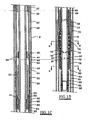
- the upper end of the running tool actuator assembly 6 may include an inner connector 14 structurally connected by threads 16 to the running tool inner mandrel 10, which in turn is structurally connected to a work string 4.
- a throughport 22 in the mandrel 10 below the top connector allows fluid pressure within the interior of the running tool to act on both inner connector 14 and an outer connector 18, which as shown includes conventional seals 2 for sealing between the mandrel 10 and an outer sleeve 12.
- a predetermined amount of fluid pressure within the running tool acting on the outer connector will thus provide downward movement of the outer sleeve 12, which is connected to the outer connector by threads 20.
- Fluid pressure to the inner connector 14 thus passes through the throughport 22, and inner connector is sealed and structurally connected to the mandrel 10. Fluid pressure thus exerts an upward force on the connector 14 and thus the mandrel 10 , and also exerts a downward force on the outer connector 18 and the outer sleeve 12.
- Figure 1B shows a similar inner connector 24 and outer connector 26 acting on the mandrel 10 and the sleeve 12, respectively with fluid entering through port 28.
- a series of outer connectors, inner connectors, sleeves and mandrels may be provided, so that forces effectively "stack" to create the desirable expansion forces.
- a series of inner and outer connectors may exert a force on the tubular expander in excess of 1.4 x 10 5 N (1,000,000 pounds) of axial force, and preferably in excess of about 2.1 x 10 5 N (1,500,000 pounds) of axial force, to expand the tubular anchor.
- the inner connector (inner piston), outer connector (outer piston), sleeve and running tool mandrel 10 thus define a variable size hydraulic cavity.
- the throughport passing through the running tool mandrel is in fluid communication with the bore 11 in the mandrel 10.
- the outer piston moves downward with respect to the inner piston.
- fluid pressure introduced into the hydraulic cavity moves the sleeve 12 downward relative to the mandrel 10 to move the tubular expander 40 downward to expand the liner hanger 48 (see Fig. 1 C) .
- a force transfer member 34 may be threaded to and move with the sleeve 12, or to a lower sleeve 32 provided on the lowermost outer piston 26, so that the force transfer shoulder on member 34 engages the top shoulder 36 on the sealing sleeve 37 at the upper end of the tubular expander 40.
- the lower shoulder 38 at the end of the force transfer sleeve engages a mating shoulder at the lower end of sealing sleeve 37 to more reliably move the tubular expander downward.
- the tubular expander is forcibly moved at least substantially within the liner hanger to expand the liner hanger 48 into engagement with the casing string 8.
- the tubular force transfer member 34 as shown in Figure 1B may thus be positioned above the tubular expander, and moves or strokes the tubular expander downward.
- the sleeve 32 also acts as a setting sleeve which is adjustably supported on the force transfer member 34 and moves in a downward direction during the liner hanger setting operation.
- the force transfer member 34 may be adjusted downward within the setting sleeve 32 at adjusting thread 31 until the lower end of the expander is in engagement with the upper end of the liner hanger, and the lower expander taper 44 is in secure contact with the upper liner hanger body taper 46 (see Figure 1 C) .
- a setting ball is thus dropped into the drill pipe and permitted to gravitate until the ball engages the seat 86 (see Fig. 1 D) at the lower end of the running tool.
- fluid may pass through port 90 in sleeve 84.
- Pressure is thereafter applied to fluid within the workstring and consequently through the pressure ports 22, 28 of the mandrel 10 and into the pressure chambers formed between the upward moving pistons 14,24 and the downward moving pistons 18,26. Pressure is increased until the force created is sufficient to cause the expander 40 to move downward relative to the mandrel 10 , forcing the expander 40 into the upward facing expansion receptacle of the liner hanger body 48. Forcing the expander 40 downward causes the liner hanger body 48 to expand radially, forcing slips 50 and sealing elements 52 into engagement with the inside surface of the casing, thus sealing and supporting the liner hanger within the casing.
- the liner hanger assembly includes a tubular anchor 48 and a tubular expander 40 positioned above the tubular anchor when run in the well.
- the tubular expander has an expander outer diameter greater than the liner hanger inner diameter, such that moving the tubular expander into the liner hanger will expand the liner hanger against the casing string to seal the liner hanger with the casing string and secure the liner hanger and the tubular expander downhole in the casing string.
- the tubular expander may be positioned above and rest on the liner hanger prior to expansion, restraining axially downward movement of the tubular expander.
- the tubular anchor and expander are solid rather than perforated or slotted.
- One or more scallops, circular arcs or circular bumps 42 on the outside of the expander sleeve 40 form a series of metal-to-metal ball seals that provide a gas tight seal between the set expander 40 and liner hanger body 48.
- the tubular expander preferably is a continuous sleeve-shaped member which radially supports the liner hanger once expanded.
- the OD and ID of the expander is substantially constant along its length (except for the annular bumps) thereby reducing the likelihood that the expander will slide out from under the set liner hanger after the running tool is retrieved to the surface.
- the upper end of the expander 40 has an upward facing sealing sleeve 37 with an internal sealing surface 35 suitable for receiving a tie-back seal nipple after the liner is installed in the well.
- the lower portion of the tubular expander 40 may thus be positioned within the liner hanger 48 to expand the liner hanger, while the upper sealing sleeve 37 integral with the tubular expander above the shoulder 38 may be used for sealing with a seal nipple for extending the liner upward.
- the liner hanger body 48 is a tubular member having elastomer, graphite or other suitable sealing elements 52 affixed about its outer circumference for sealing with the casing upon expansion of the liner hanger.
- a plurality of gripping members, such as slips 50, may be provided on the liner hanger for securing the liner hanger to the casing string 8 upon expansion.
- the upper larger internal diameter of the liner hanger provides an expansion receptacle for the tubular expander 40.
- the lower end of the running tool preferably engages the tubular anchor while the expander is pushed downward into the tubular anchor.
- the lower end of the liner hanger has a thread connection 68 for connection to the liner or other tubular components.
- the inner diameter of the lower portion 65 of the liner hanger which is not expanded is approximately the same as that of the liner 98.
- the upper end of the liner hanger has an inwardly facing taper or incline 46 that provides for overlapping internal engagement of a mating taper 44 on the bottom of the tubular expander 40. This allows the tapered end of the tubular expander to be at least partially inserted into an upper end of the liner hanger prior to expansion of the tubular anchor.
- the sleeve-shaped expander sleeve thus provides substantial radial support to the tubular anchor once the running tool is returned to the surface. This increased radial support to the anchor maintains fluid tight engagement between the liner hanger and casing string.
- the running tool may then be retrieved leaving the expander sleeve positioned radially inward of and axially aligned with the liner hanger to maintain the liner hanger in gripping engagement with the casing string.
- the hydraulic running tool is connected to internal threads 59 in the liner hanger central body 62 by means of external threads 60 on releasable collet fingers 56.
- the collet fingers extend from collet ring 54 which is supported on running tool mandrel 10.
- the collet finger heads 58 are prevented from flexing inwardly by the releasing nut 63 that is connected to mandrel 10 by a left hand thread at 64. It should be remembered that the mandrel 10 of the running tool moves in an upward direction during setting of the liner hanger slips, and becomes stationary once the slips are set.
- the actuator assembly of the running tool may be removed by unthreading the threaded 64 connection.
- the left-hand threaded connection 64 prevents undesirable unthreading of the tubular right-hand connections, which typically join tubulars and threaded components of downhole tools.
- the nut 63 is then free to fall or be moved from its position supporting the inner surface of the collet fingers 56.
- the nut 63 is caught on coupling 66 and mandrel shoulder 51 is raised to engage collet ring shoulder 53. Upward force applied to the collet ring causes the collet fingers 52 to flex inwardly moving external threads on the collet fingers from engagement with the internal threads of the liner hanger body.
- the running tool is then free to be removed from the set liner hanger.
- a seal nipple may be inserted into the upper sealing sleeve portion 37 of the tubular expander 40, until the shoulder of the seal nipple contacts the upper end of the sealing sleeve.
- the lower end of the seal nipple may also engage the shoulder 38 on the expander when the sealing nipple is fully inserted into the expander.
- the sealing sleeve 37 of the tubular expander may be an upwardly extending sealing sleeve which is preferably integral with the upper end of expander 40 for sealing with the seal nipple.
- the sealing sleeve preferably has a polished cylindrical inner surface for sealing with a cylindrical outer surface of the seal nipple.
- the sealing sleeve could have a polished cylindrical outer surface for sealing with a cylindrical inner surface of the seal nipple.
- the seal nipple may also include an elastomeric seal, such as a Chevron seal stack, for sealing with the cylindrical inner surface of the sealing sleeve.
- a seal nipple may also be furnished with one or more external metal-to-metal ball seals for metal-to-metal sealing engagement with inner surface of sealing sleeve.
- the sealing sleeve and the seal nipple form an expansion joint that allows for thermal expansion and contraction of the tubular string above the seal nipple.
- the internal diameter of the sealing nipple and the tubular above the sealing nipple may thus be substantially the same as the internal diameter of the tubular expander radially within the tubular anchor.
- a feature of the described expandable liner hanger is that there are no moving parts on the liner hanger that may become disengaged from the liner hanger body during installation of the liner in the well, thereby making it difficult or impossible to get the liner to the required setting depth. For that reason, the expandable liner hanger is particularly desirable for its adaptation for use in liner drilling operations.
- This is a technique for drilling the well by positioning a drill bit at the bottom of the liner and rotating the drill pipe (workstring) and liner to drill the liner into the well. In order to drill the liner into the well, relative rotation is prohibited between the liner and the running tool and drill pipe during this operation.
- a torque sub 70 having axial grooves is installed as a part cf the liner 98 and is positioned adjacent spring biased dogs 74 that are retained in a cage 72 that is selectively rotatable about the mandrel 10 of the running tool. More particularly, torque sub 70 is threaded at 68 with the liner hanger lower body 65.
- the cage 72 has lower facing clutch jaws 73 at its lower end that are interlocked with mating upper facing clutch jaws located on the upper end spline bushing 76 when the running tool is in the running position.
- Springs 74 allow the plugs to move radially forward and pass by the smaller diameter liner hanger before enforcing the axial grooves in the torque sub 70.
- the spline bushing 76 has a series of internal axial splines 78 (see Fig. 2 ) that slidably interconnect with external axial splines on the mandrel 10, Shear pins 95 extend through the spline bushing and engage an annular groove in the mandrel 10 to releasably secure the spline sub in an axial position to maintain engagement of the lower clutch jaws 73 and upper clutch jaws.
- the running tool includes a sufficiently large bore to allow for the reliable passage of cement and one or more cementing plugs to pass through the bore of the running tool and cement the liner in place. More particularly, the running tool preferably has an internal diameter which is at least 50.8 mm (two inches), and in many applications will have a 76.2 mm (three inch) or greater internal diameter. Cement may thus be pumped from the surface through the workstring and through the liner hanger, then out the lower end of the liner and into the annulus between the liner and the borehole. Once the proper amount of cement is pumped into location, the liner hanger may be set.
- release from the liner hanger is accomplished by establishing relative rotation between the liner and the running tool after disengaging the clutch jaws 73 between the cage 72 and the spline bushing 76. This is accomplished through the use of hydraulic pressure applied through port 87 in the mandrel 10 into a differential pressure chamber established between mandrel seal 57 and spline bushing seal 97. Sufficient pressure is applied to create force thus necessary to break shear pins 45 and shift spline bushing 76 along mandrel 10 until spline bushing engages upper shoulder 83 of seat sub 82, which is threaded at 84 to mandrel 10.
- the mandrel 10 is then permitted to rotate relative to the cage 72, allowing the mandrel 10 of the running tool to be rotated relative to the releasing nut 63 to disengage the running tool from the liner hanger.
- the dogs 74 may move radially inward as the running tool is raised upward past the set liner hanger.
- Figure 1E shows the lower portion of the running tool and an upper portion of the liner 98, which is threaded at 96 to the lower sleeve of the sub 70.
- Various lengths of the liner may be threaded together, as shown at 102.
- the lower end of seat sub 82 is threaded at 92 to central flow tube 94, which passes cement to a lower portion of the well.
- Bushing 100 is provided for sealing between the central flow tube 94 and the liner hanger 98.
- Figure 4 depicts a portion of the set liner hanger 48 with the tubular expander 40 therein and the sealing sleeve 37 integral with the tubular expander and extending upward from the tubular expander.
- a sealing nipple 120 is shown positioned within the sealing sleeve and is sealed thereto in a conventional manner, optionally by an annular metal-to-metal ball seal 140.
- An upper liner extension 122 with a large bore I.D. substantially equal to that of the sealing sleeve and the tubular expander is shown connected to the sealing nipple 120 at threads 124. Fluid may thus pass upward from the liner hung in the well from the liner hanger, past the tubular expander, through the sealing nipple, and upward to the surface through the liner extension.
Landscapes
- Geology (AREA)
- Life Sciences & Earth Sciences (AREA)
- Engineering & Computer Science (AREA)
- Mining & Mineral Resources (AREA)
- Environmental & Geological Engineering (AREA)
- Fluid Mechanics (AREA)
- Physics & Mathematics (AREA)
- General Life Sciences & Earth Sciences (AREA)
- Geochemistry & Mineralogy (AREA)
- Earth Drilling (AREA)
- Compositions Of Macromolecular Compounds (AREA)
- Manufacture Of Macromolecular Shaped Articles (AREA)
- Load-Engaging Elements For Cranes (AREA)
Claims (10)
- Liner-Hänger zur Verwendung im Bohrloch in einer Bohrung zur Abdichtung mit einem Auskleidungsstrang und zum Tragen eines Liners (98) an dem Liner-Hänger, wobei der Liner-Hänger einen rohrförmigen Liner-Hänger (48) umfaßt, der abnehmbar abstützbar auf einem beweglichen Werkzeug zum Positionieren des rohrförmigen Liner-Hängers (48) im Bohrloch ist, wobei der rohrförmige Liner-Hänger (48) einen anfänglichen inneren Hängerdurchmesser aufweist und einen anfänglichen äußeren Hängerdurchmesser ausweist, der kleiner ist als ein inner Durchmesser des Auskleidungsstrangs, wobei der rohrförmige Liner-Hänger (48) durch das bewegliche Werkzeug expandiert werden kann, um mit dem Auskleidungsstrang abzudichten, wobei der Liner-Hänger den Liner in der Bohrung trägt, und wobei das bewegliche Werkzeug einen Aktuator (6) umfaßt, dadurch gekennzeichnet, daß der Liner-Hänger umfaßt:einen rohrförmigen Expander (40) der abnehmbar auf dem beweglichen Werkzeug abgestützt werden kann, wobei der rohrförmige Expander (40) einen äußersten Expanderdurchmesser aufweist, der größer ist als der anfängliche innere Hängerdurcl-irnesser; undwobei das bewegliche Werkzeug den rohrförmigen Expander (48) zwangsweise in axialer Richtung bewegt, ausgehend von einer Position, die im wesentlichen in axialer Richtung von dem rohrförmigen Liner-Hänger (48) beabstandet ist, in eine Position, die im wesentlichen innerhalb des rohrförmigen Liner-Hängers (48) liegt, wobei dadurch der rohrförmige Hänger (48) gegen den Auskleiduugsstrang in radialer Richtung expandiert wird, um den rohrformigen Expander (40) und den rohrformigen Hänger (48) im Bohrloch zu befestigen, wobei das bewegliche Werkzeug eine innere Bohrung aufweist, um ein Bindemittel durch das bewegliche Werkzeug und aus einem unteren Ende des Liners heraus durchzuleiten.
- Liner-Hängcr nach Anspruch 1, dadurch gekennzeichnet, daß der rohrförmige Expander (40) gegenüber dem rohrförmigen Liner-Hänger durch eine oder mehrere ringförmige Erhebungen (42) auf einer äußeren Oberfläche des rohrförmigen Expanders (40) abgedichtet ist.
- Liner-Hänger nach einem der vorangehenden Ansprüche, weiter umfassend:einen oder mehrere Nocken (74), jeweils zum Erfassen eines Schlitzes in dem Liner, um den oder die Nocken mit dem Liner zu verriegeln; undeine Kupplung (73) zum selektiven Verriegeln und Freigeben einer Drehung zwischen einem beweglichen Werkzeugdorn (10) und dem oder den Nocken, so daß sich der Liner mit dem beweglichen Werkzeugdorn (10) dreht, wenn sich die Kupplung (73) im Eingriff befindet, und der bewegliche Werkzeugdorn (10) bezüglich einer Drehung von dem Liner gelöst ist, wenn die Kupplung (73) gelöst ist.
- Liner-Hänger nach Anspruch 3, weiter umfassend einen Kolben (14, 18), der in axialer Richtung ansprechend auf einen Fluiddruck innerhalb des beweglichen Werkzeugdorns (10) bewegbar ist, wobei die Kupplung (73) ansprechend auf eine axiale Bewegung des Kolbens (14, 18) gelöst wird.
- Verfahren zum Hängen eines Liners (98) in eine Bohrung zum Abdichten mit einem Auskleidungsstrang, wobei die Verbesserung umfaßt:Positionieren eines expandierbaren rohrförmigen Liner-Hängers (48) und eines rohrförmigen Expanders (40) an einem beweglichen Werkzeug, wobei der rohrförmige Liner-Hänger (48) einen anfänglichen inneren Durchmesser des Liner-Hängers aufweist, und einen anfänglichen äußeren Durchmesser des Liner-Hängers, der geringer ist als ein innerer Durchmesser des Auskleidungsstrangs, wobei der rohrförmige Expander (40) einen äußersten Expanderdurchmesser ausweist, der größer ist als der anfängliche innere Durchmesser des Liner-Hängers, und wobei eine Dichthülse (37) an einem oberen Ende des rohrförmigen Expanders (40) befestigt ist;Positionieren des Linef-Häaxgers in einer ausgewählten Tiefe innerhalb einer Bohrung;Hindurchleiten von Bindemittel durch den rohrförmigen Expander (40) und den Liner, um den Liner in der Bohrung zu verkleben; undzwangsweises Bewegen des rohrförmigen Expanders (40) in axialer Richtung in einer Position im wesentlichen innerhalb des rohrförmigen Liner-Hängers (48), um den rohrförmigen Liner-Hänger (48) in radialer Richtung gegen den Auskleidungsstrang aufzuweiten, so daß dadurch der rohrformige Liner-Hänger (48) und der rohrformige Expander (45) im Bohrloch befestigt werden.
- Verfahren nach Anspruch 5, weiter umfassend:Positionieren des rohrförmigen Expanders (40) oberhalb des rohrförmigen Liner-Hängers (48), bevor der rohrformige Expander (40) zwangsweise im wesentlichen innerhalb des rohrförmigen Lizler-Hängers (48) bewegt wird.
- Verfahren nach Anspruch 5 oder 6, weiter umfassend:Abdichten des rohrformigen Expanders (40) gegenüber dem rohrförmigen Liner-Hänger durch eine oder mehrere ringförmige Erhebungen (42) auf einer äußeren Oberfläche des rohrförmigen Expanders (46).
- Verfahren nach Anspruch 5, 6 oder 7, weiter umfassend:Anordnen von einer oder mehreren Packungsdichtungen (52) auf dem rohrförmigen Liner-Hänger (48) zum Abdichten mit dem Auskleidungsstrang bei der Expansion des rohrförmigen Liner-Hängers (48); undBefestigen einer Anzahl von Belegen (50) auf dem rohrförmigen Liner-Hänger (48) zum Befestigen des rohrförmigen Hängers (48) an dem Auskleidungsstrang, wenn der rohrförmige Liner-Hänger (48) durch den rohrförmigen Expander (40) expandiert wird.
- Verfahren nach Anspruch 5, 6, 7 oder 8, weiter umfassend;in Eingriff bringen von einem oder mehreren Nocken (74) jeweils mit einem Schlitz in dem Liner, um den oder die Nocken mit dem Liner bezüglich einer Drehung zu verriegeln; undselektives Verriegeln und Freigeben einer Kupplung (73) zur Drehung zwischen einem beweglichen Werkzeugdorn (10) um dem Anschlag oder den Anschlägen, so daß sich der Liner mit dem beweglichen Werkzeugdorn (10) dreht, wenn sich die Kupplung (73) im Eingriff befindet, und der bewegliche Werkzeugdorn (10) bezüglich einer Drehung von dem Liner gelöst ist, wenn die Kupplung (73) gelöst ist.
- Verfahren nach Anspruch 9, weiter umfassend:Bewegen eines Kolbens (14, 18) in axialer Richtung ansprechend auf einen Fluiddruck innerhalb des beweglichen Werkzeugdorns (10), um die Kupplung (73) selektiv außer Eingriff zu bringen.
Applications Claiming Priority (3)
| Application Number | Priority Date | Filing Date | Title |
|---|---|---|---|
| US855044 | 2004-05-27 | ||
| US10/855,044 US7225880B2 (en) | 2004-05-27 | 2004-05-27 | Expandable liner hanger system and method |
| US11/138,838 US7278492B2 (en) | 2004-05-27 | 2005-05-26 | Expandable liner hanger system and method |
Publications (3)
| Publication Number | Publication Date |
|---|---|
| EP1600600A2 EP1600600A2 (de) | 2005-11-30 |
| EP1600600A3 EP1600600A3 (de) | 2006-03-01 |
| EP1600600B1 true EP1600600B1 (de) | 2008-07-16 |
Family
ID=37907019
Family Applications (1)
| Application Number | Title | Priority Date | Filing Date |
|---|---|---|---|
| EP05011480A Expired - Lifetime EP1600600B1 (de) | 2004-05-27 | 2005-05-27 | Expandierbare Liner-Hängervorrichtung und Verfahren |
Country Status (5)
| Country | Link |
|---|---|
| US (2) | US7225880B2 (de) |
| EP (1) | EP1600600B1 (de) |
| CA (1) | CA2508434C (de) |
| NO (1) | NO335123B1 (de) |
| WO (1) | WO2006127981A2 (de) |
Cited By (1)
| Publication number | Priority date | Publication date | Assignee | Title |
|---|---|---|---|---|
| CN102953698A (zh) * | 2011-08-23 | 2013-03-06 | 中国石油化工股份有限公司 | 一种膨胀式可旋转尾管悬挂器 |
Families Citing this family (84)
| Publication number | Priority date | Publication date | Assignee | Title |
|---|---|---|---|---|
| US8936101B2 (en) | 2008-07-17 | 2015-01-20 | Halliburton Energy Services, Inc. | Interventionless set packer and setting method for same |
| US7503395B2 (en) | 2005-05-21 | 2009-03-17 | Schlumberger Technology Corporation | Downhole connection system |
| CA2609184C (en) * | 2005-05-26 | 2011-11-15 | Tiw Corporation | Expandable liner hanger system and method |
| US20070068703A1 (en) * | 2005-07-19 | 2007-03-29 | Tesco Corporation | Method for drilling and cementing a well |
| BRPI0616909A2 (pt) * | 2005-10-05 | 2011-07-05 | Tesco Corp | método para perfuração com um revestimento auxiliar de poço |
| US20080245535A1 (en) * | 2007-04-04 | 2008-10-09 | Mcanally Yvonne B | Actuation tool |
| AU2012201115B2 (en) * | 2007-04-20 | 2015-04-02 | Halliburton Energy Services, Inc. | Running tool for expandable liner hanger and associated methods |
| US8393389B2 (en) * | 2007-04-20 | 2013-03-12 | Halliburton Evergy Services, Inc. | Running tool for expandable liner hanger and associated methods |
| US7845421B2 (en) * | 2007-05-12 | 2010-12-07 | Tiw Corporation | Downhole tubular expansion tool and method |
| US8132627B2 (en) * | 2007-05-12 | 2012-03-13 | Tiw Corporation | Downhole tubular expansion tool and method |
| US7878240B2 (en) * | 2007-06-05 | 2011-02-01 | Baker Hughes Incorporated | Downhole swaging system and method |
| US7926590B2 (en) * | 2007-10-03 | 2011-04-19 | Tesco Corporation | Method of liner drilling and cementing utilizing a concentric inner string |
| US8100188B2 (en) * | 2007-10-24 | 2012-01-24 | Halliburton Energy Services, Inc. | Setting tool for expandable liner hanger and associated methods |
| US7779910B2 (en) | 2008-02-07 | 2010-08-24 | Halliburton Energy Services, Inc. | Expansion cone for expandable liner hanger |
| WO2009137536A1 (en) * | 2008-05-05 | 2009-11-12 | Weatherford/Lamb, Inc. | Tools and methods for hanging and/or expanding liner strings |
| US8540035B2 (en) | 2008-05-05 | 2013-09-24 | Weatherford/Lamb, Inc. | Extendable cutting tools for use in a wellbore |
| US7967077B2 (en) | 2008-07-17 | 2011-06-28 | Halliburton Energy Services, Inc. | Interventionless set packer and setting method for same |
| US7854266B2 (en) * | 2008-09-26 | 2010-12-21 | Halliburton Energy Services, Inc. | Smooth bore latch for tie back receptacle extension |
| US20100155084A1 (en) * | 2008-12-23 | 2010-06-24 | Halliburton Energy Services, Inc. | Setting tool for expandable liner hanger and associated methods |
| US20100155082A1 (en) * | 2008-12-23 | 2010-06-24 | Braddick Britt O | Actuator Assembly for Tubular Expansion |
| US8453729B2 (en) | 2009-04-02 | 2013-06-04 | Key Energy Services, Llc | Hydraulic setting assembly |
| US9303477B2 (en) | 2009-04-02 | 2016-04-05 | Michael J. Harris | Methods and apparatus for cementing wells |
| US8684096B2 (en) * | 2009-04-02 | 2014-04-01 | Key Energy Services, Llc | Anchor assembly and method of installing anchors |
| US8066078B2 (en) * | 2009-08-06 | 2011-11-29 | Tiw Corporation | Overshot tool and method |
| US20110048741A1 (en) * | 2009-09-01 | 2011-03-03 | Enventure Global Technology | Downhole telescoping tool with radially expandable members |
| US8261842B2 (en) * | 2009-12-08 | 2012-09-11 | Halliburton Energy Services, Inc. | Expandable wellbore liner system |
| US8371388B2 (en) * | 2009-12-08 | 2013-02-12 | Halliburton Energy Services, Inc. | Apparatus and method for installing a liner string in a wellbore casing |
| NO346185B1 (no) * | 2010-01-11 | 2022-04-11 | Tiw Corp | Tubulært ekspansjonsverktøy og fremgangsmåte |
| US8408317B2 (en) * | 2010-01-11 | 2013-04-02 | Tiw Corporation | Tubular expansion tool and method |
| US8286718B2 (en) * | 2010-01-29 | 2012-10-16 | Tiw Corporation | Downhole tubular expander and method |
| CA2790722A1 (en) * | 2010-02-23 | 2011-09-01 | Tesco Corporation | Apparatus and method for cementing liner |
| US9725992B2 (en) | 2010-11-24 | 2017-08-08 | Halliburton Energy Services, Inc. | Entry guide formation on a well liner hanger |
| US8863847B2 (en) | 2010-12-13 | 2014-10-21 | Cameron International Corporation | Adjustable riser suspension and sealing system |
| CN102041973B (zh) * | 2010-12-22 | 2013-01-09 | 中国石油天然气集团公司 | 小井眼悬挂器 |
| US8985227B2 (en) | 2011-01-10 | 2015-03-24 | Schlumberger Technology Corporation | Dampered drop plug |
| US9528352B2 (en) | 2011-02-16 | 2016-12-27 | Weatherford Technology Holdings, Llc | Extrusion-resistant seals for expandable tubular assembly |
| US11215021B2 (en) | 2011-02-16 | 2022-01-04 | Weatherford Technology Holdings, Llc | Anchoring and sealing tool |
| US20120205092A1 (en) | 2011-02-16 | 2012-08-16 | George Givens | Anchoring and sealing tool |
| US8997882B2 (en) | 2011-02-16 | 2015-04-07 | Weatherford Technology Holdings, Llc | Stage tool |
| AU2012217608B2 (en) | 2011-02-16 | 2016-05-12 | Weatherford Technology Holdings, Llc | Anchoring seal |
| US8851167B2 (en) | 2011-03-04 | 2014-10-07 | Schlumberger Technology Corporation | Mechanical liner drilling cementing system |
| US9121232B2 (en) | 2011-03-14 | 2015-09-01 | Smith International, Inc. | Hydro-mechanical downhole tool |
| US20120241171A1 (en) * | 2011-03-24 | 2012-09-27 | Baker Hughes Incorporated | Multiple Liner Hanger Assembly |
| US9556680B2 (en) * | 2011-03-26 | 2017-01-31 | Halliburton Energy Services, Inc. | Single trip liner setting and drilling assembly and methods |
| CA2811638C (en) | 2012-04-05 | 2016-04-26 | Key Energy Services, Llc | Methods and apparatus for cementing wells |
| US9260926B2 (en) | 2012-05-03 | 2016-02-16 | Weatherford Technology Holdings, Llc | Seal stem |
| US9145822B2 (en) | 2012-07-16 | 2015-09-29 | Ford Global Technologies, Llc | Method and device for controlling a four-stroke internal combustion engine |
| US9145734B2 (en) * | 2012-11-30 | 2015-09-29 | Baker Hughes Incorporated | Casing manipulation assembly with hydraulic torque locking mechanism |
| WO2014098885A1 (en) * | 2012-12-21 | 2014-06-26 | Halliburton Energy Services, Inc. | Improved liner hanger system |
| US9580981B2 (en) | 2012-12-21 | 2017-02-28 | Halliburton Energy Services, Inc. | Liner hanger system |
| WO2014137314A1 (en) * | 2013-03-04 | 2014-09-12 | Halliburton Energy Services, Inc. | Abandonment and containment system for gas wells |
| EP3049606B1 (de) * | 2013-12-05 | 2021-01-06 | Halliburton Energy Services, Inc. | Einstellwerkzeug für rohraufhänger und verfahren zur verwendung davon |
| CN103790533B (zh) * | 2014-01-03 | 2016-08-17 | 中国石油天然气股份有限公司 | 可固井膨胀式尾管悬挂器 |
| WO2015105487A1 (en) * | 2014-01-08 | 2015-07-16 | Halliburton Energy Services, Inc. | Running tool and liner hanger contingency release mechanism |
| US9810037B2 (en) | 2014-10-29 | 2017-11-07 | Weatherford Technology Holdings, Llc | Shear thickening fluid controlled tool |
| US10180038B2 (en) | 2015-05-06 | 2019-01-15 | Weatherford Technology Holdings, Llc | Force transferring member for use in a tool |
| US10563475B2 (en) | 2015-06-11 | 2020-02-18 | Saudi Arabian Oil Company | Sealing a portion of a wellbore |
| US9650859B2 (en) | 2015-06-11 | 2017-05-16 | Saudi Arabian Oil Company | Sealing a portion of a wellbore |
| US9482062B1 (en) | 2015-06-11 | 2016-11-01 | Saudi Arabian Oil Company | Positioning a tubular member in a wellbore |
| WO2017105807A1 (en) * | 2015-12-14 | 2017-06-22 | Schlumberger Technology Corporation | Hoop stress hydraulic trigger |
| US9896914B2 (en) | 2016-01-07 | 2018-02-20 | Tiw Corporation | Downhole tubular expansion tool and method |
| US10100620B2 (en) | 2016-05-31 | 2018-10-16 | Tiw Corporation | Downhole tubular expansion tool and method for installing a tandem clad liner |
| US10337298B2 (en) * | 2016-10-05 | 2019-07-02 | Tiw Corporation | Expandable liner hanger system and method |
| US10316619B2 (en) | 2017-03-16 | 2019-06-11 | Saudi Arabian Oil Company | Systems and methods for stage cementing |
| US10544648B2 (en) | 2017-04-12 | 2020-01-28 | Saudi Arabian Oil Company | Systems and methods for sealing a wellbore |
| US10557330B2 (en) | 2017-04-24 | 2020-02-11 | Saudi Arabian Oil Company | Interchangeable wellbore cleaning modules |
| US10378298B2 (en) | 2017-08-02 | 2019-08-13 | Saudi Arabian Oil Company | Vibration-induced installation of wellbore casing |
| US10487604B2 (en) | 2017-08-02 | 2019-11-26 | Saudi Arabian Oil Company | Vibration-induced installation of wellbore casing |
| US10597962B2 (en) | 2017-09-28 | 2020-03-24 | Saudi Arabian Oil Company | Drilling with a whipstock system |
| US10378339B2 (en) | 2017-11-08 | 2019-08-13 | Saudi Arabian Oil Company | Method and apparatus for controlling wellbore operations |
| US10704339B2 (en) * | 2017-11-17 | 2020-07-07 | Halliburton Energy Services, Inc. | Releasable connection mechanism for use within a well |
| US10689913B2 (en) | 2018-03-21 | 2020-06-23 | Saudi Arabian Oil Company | Supporting a string within a wellbore with a smart stabilizer |
| US10689914B2 (en) | 2018-03-21 | 2020-06-23 | Saudi Arabian Oil Company | Opening a wellbore with a smart hole-opener |
| US10794170B2 (en) | 2018-04-24 | 2020-10-06 | Saudi Arabian Oil Company | Smart system for selection of wellbore drilling fluid loss circulation material |
| US10612362B2 (en) | 2018-05-18 | 2020-04-07 | Saudi Arabian Oil Company | Coiled tubing multifunctional quad-axial visual monitoring and recording |
| CN112227992B (zh) * | 2019-07-15 | 2024-07-26 | 中国石油化工股份有限公司 | 双悬挂双密封式耐高温膨胀悬挂器 |
| US11299968B2 (en) | 2020-04-06 | 2022-04-12 | Saudi Arabian Oil Company | Reducing wellbore annular pressure with a release system |
| GB2609842B (en) | 2020-06-29 | 2024-04-10 | Halliburton Energy Services Inc | Expandable liner hanger with post-setting fluid flow path |
| US11396789B2 (en) | 2020-07-28 | 2022-07-26 | Saudi Arabian Oil Company | Isolating a wellbore with a wellbore isolation system |
| US11414942B2 (en) | 2020-10-14 | 2022-08-16 | Saudi Arabian Oil Company | Packer installation systems and related methods |
| CN114737902B (zh) * | 2021-01-07 | 2024-09-20 | 中国石油化工股份有限公司 | 一种具有机械和液压丢手方式的尾管悬挂器 |
| US11624265B1 (en) | 2021-11-12 | 2023-04-11 | Saudi Arabian Oil Company | Cutting pipes in wellbores using downhole autonomous jet cutting tools |
| CN114991692B (zh) * | 2022-06-01 | 2024-01-16 | 淮安市井神钻采机具有限公司 | 复合超膨胀固井尾管悬挂器 |
| WO2025081273A1 (en) * | 2023-10-17 | 2025-04-24 | Torsch Inc. | Drillable bridge plug for supercritical wells |
Family Cites Families (10)
| Publication number | Priority date | Publication date | Assignee | Title |
|---|---|---|---|---|
| US3948321A (en) | 1974-08-29 | 1976-04-06 | Gearhart-Owen Industries, Inc. | Liner and reinforcing swage for conduit in a wellbore and method and apparatus for setting same |
| US4051896A (en) * | 1974-12-18 | 1977-10-04 | Otis Engineering Corporation | Well bore liner hanger |
| US3946807A (en) * | 1974-12-18 | 1976-03-30 | Otis Engineering Corporation | Well tools |
| AU770359B2 (en) | 1999-02-26 | 2004-02-19 | Shell Internationale Research Maatschappij B.V. | Liner hanger |
| US6276690B1 (en) | 1999-04-30 | 2001-08-21 | Michael J. Gazewood | Ribbed sealing element and method of use |
| US6499537B1 (en) * | 1999-05-19 | 2002-12-31 | Smith International, Inc. | Well reference apparatus and method |
| US6598677B1 (en) | 1999-05-20 | 2003-07-29 | Baker Hughes Incorporated | Hanging liners by pipe expansion |
| US6752215B2 (en) | 1999-12-22 | 2004-06-22 | Weatherford/Lamb, Inc. | Method and apparatus for expanding and separating tubulars in a wellbore |
| US6648075B2 (en) * | 2001-07-13 | 2003-11-18 | Weatherford/Lamb, Inc. | Method and apparatus for expandable liner hanger with bypass |
| US7093656B2 (en) * | 2003-05-01 | 2006-08-22 | Weatherford/Lamb, Inc. | Solid expandable hanger with compliant slip system |
-
2004
- 2004-05-27 US US10/855,044 patent/US7225880B2/en not_active Expired - Lifetime
-
2005
- 2005-05-26 NO NO20052561A patent/NO335123B1/no unknown
- 2005-05-26 CA CA2508434A patent/CA2508434C/en not_active Expired - Lifetime
- 2005-05-26 US US11/138,838 patent/US7278492B2/en not_active Expired - Lifetime
- 2005-05-27 EP EP05011480A patent/EP1600600B1/de not_active Expired - Lifetime
-
2006
- 2006-05-25 WO PCT/US2006/020395 patent/WO2006127981A2/en not_active Ceased
Cited By (2)
| Publication number | Priority date | Publication date | Assignee | Title |
|---|---|---|---|---|
| CN102953698A (zh) * | 2011-08-23 | 2013-03-06 | 中国石油化工股份有限公司 | 一种膨胀式可旋转尾管悬挂器 |
| CN102953698B (zh) * | 2011-08-23 | 2015-08-26 | 中国石油化工股份有限公司 | 一种膨胀式可旋转尾管悬挂器 |
Also Published As
| Publication number | Publication date |
|---|---|
| US20050263292A1 (en) | 2005-12-01 |
| CA2508434A1 (en) | 2005-11-27 |
| US7225880B2 (en) | 2007-06-05 |
| NO335123B1 (no) | 2014-09-22 |
| CA2508434C (en) | 2010-11-16 |
| WO2006127981A2 (en) | 2006-11-30 |
| US7278492B2 (en) | 2007-10-09 |
| EP1600600A3 (de) | 2006-03-01 |
| EP1600600A2 (de) | 2005-11-30 |
| WO2006127981A3 (en) | 2007-12-27 |
| NO20052561L (no) | 2005-11-28 |
| NO20052561D0 (no) | 2005-05-26 |
| US20050263294A1 (en) | 2005-12-01 |
Similar Documents
| Publication | Publication Date | Title |
|---|---|---|
| EP1600600B1 (de) | Expandierbare Liner-Hängervorrichtung und Verfahren | |
| CA2979460C (en) | EXTENDABLE HANGING COLUMN SUSPENSION SYSTEM AND METHOD | |
| CA2449340C (en) | Wellbore apparatus and method | |
| US7441606B2 (en) | Expandable fluted liner hanger and packer system | |
| US7093656B2 (en) | Solid expandable hanger with compliant slip system | |
| US6763893B2 (en) | Downhole tubular patch, tubular expander and method | |
| US7028780B2 (en) | Expandable hanger with compliant slip system | |
| EP1392953B1 (de) | Leitungshänger, einbauwerkzeug und verfahren | |
| US7124827B2 (en) | Expandable whipstock anchor assembly | |
| EP2823131B1 (de) | Vorrichtung und verfahren zum betreiben eines dehnbaren futters | |
| US8286718B2 (en) | Downhole tubular expander and method | |
| CA2609184C (en) | Expandable liner hanger system and method | |
| CA2576536C (en) | Expandable fluted liner hanger and packer system |
Legal Events
| Date | Code | Title | Description |
|---|---|---|---|
| PUAI | Public reference made under article 153(3) epc to a published international application that has entered the european phase |
Free format text: ORIGINAL CODE: 0009012 |
|
| AK | Designated contracting states |
Kind code of ref document: A2 Designated state(s): AT BE BG CH CY CZ DE DK EE ES FI FR GB GR HU IE IS IT LI LT LU MC NL PL PT RO SE SI SK TR |
|
| AX | Request for extension of the european patent |
Extension state: AL BA HR LV MK YU |
|
| PUAL | Search report despatched |
Free format text: ORIGINAL CODE: 0009013 |
|
| AK | Designated contracting states |
Kind code of ref document: A3 Designated state(s): AT BE BG CH CY CZ DE DK EE ES FI FR GB GR HU IE IS IT LI LT LU MC NL PL PT RO SE SI SK TR |
|
| AX | Request for extension of the european patent |
Extension state: AL BA HR LV MK YU |
|
| 17P | Request for examination filed |
Effective date: 20060427 |
|
| 17Q | First examination report despatched |
Effective date: 20060907 |
|
| AKX | Designation fees paid |
Designated state(s): AT BE BG CH CY CZ DE DK EE ES FI FR GB GR HU IE IS IT LI LT LU MC NL PL PT RO SE SI SK TR |
|
| GRAP | Despatch of communication of intention to grant a patent |
Free format text: ORIGINAL CODE: EPIDOSNIGR1 |
|
| GRAS | Grant fee paid |
Free format text: ORIGINAL CODE: EPIDOSNIGR3 |
|
| GRAA | (expected) grant |
Free format text: ORIGINAL CODE: 0009210 |
|
| AK | Designated contracting states |
Kind code of ref document: B1 Designated state(s): AT BE BG CH CY CZ DE DK EE ES FI FR GB GR HU IE IS IT LI LT LU MC NL PL PT RO SE SI SK TR |
|
| REG | Reference to a national code |
Ref country code: GB Ref legal event code: FG4D |
|
| REG | Reference to a national code |
Ref country code: CH Ref legal event code: EP |
|
| REF | Corresponds to: |
Ref document number: 602005008135 Country of ref document: DE Date of ref document: 20080828 Kind code of ref document: P |
|
| REG | Reference to a national code |
Ref country code: IE Ref legal event code: FG4D |
|
| NLV1 | Nl: lapsed or annulled due to failure to fulfill the requirements of art. 29p and 29m of the patents act | ||
| PG25 | Lapsed in a contracting state [announced via postgrant information from national office to epo] |
Ref country code: NL Free format text: LAPSE BECAUSE OF FAILURE TO SUBMIT A TRANSLATION OF THE DESCRIPTION OR TO PAY THE FEE WITHIN THE PRESCRIBED TIME-LIMIT Effective date: 20080716 Ref country code: IS Free format text: LAPSE BECAUSE OF FAILURE TO SUBMIT A TRANSLATION OF THE DESCRIPTION OR TO PAY THE FEE WITHIN THE PRESCRIBED TIME-LIMIT Effective date: 20081116 Ref country code: LT Free format text: LAPSE BECAUSE OF FAILURE TO SUBMIT A TRANSLATION OF THE DESCRIPTION OR TO PAY THE FEE WITHIN THE PRESCRIBED TIME-LIMIT Effective date: 20080716 Ref country code: PT Free format text: LAPSE BECAUSE OF FAILURE TO SUBMIT A TRANSLATION OF THE DESCRIPTION OR TO PAY THE FEE WITHIN THE PRESCRIBED TIME-LIMIT Effective date: 20081216 Ref country code: ES Free format text: LAPSE BECAUSE OF FAILURE TO SUBMIT A TRANSLATION OF THE DESCRIPTION OR TO PAY THE FEE WITHIN THE PRESCRIBED TIME-LIMIT Effective date: 20081027 |
|
| PG25 | Lapsed in a contracting state [announced via postgrant information from national office to epo] |
Ref country code: AT Free format text: LAPSE BECAUSE OF FAILURE TO SUBMIT A TRANSLATION OF THE DESCRIPTION OR TO PAY THE FEE WITHIN THE PRESCRIBED TIME-LIMIT Effective date: 20080716 Ref country code: BG Free format text: LAPSE BECAUSE OF FAILURE TO SUBMIT A TRANSLATION OF THE DESCRIPTION OR TO PAY THE FEE WITHIN THE PRESCRIBED TIME-LIMIT Effective date: 20081016 Ref country code: FI Free format text: LAPSE BECAUSE OF FAILURE TO SUBMIT A TRANSLATION OF THE DESCRIPTION OR TO PAY THE FEE WITHIN THE PRESCRIBED TIME-LIMIT Effective date: 20080716 Ref country code: SI Free format text: LAPSE BECAUSE OF FAILURE TO SUBMIT A TRANSLATION OF THE DESCRIPTION OR TO PAY THE FEE WITHIN THE PRESCRIBED TIME-LIMIT Effective date: 20080716 |
|
| PG25 | Lapsed in a contracting state [announced via postgrant information from national office to epo] |
Ref country code: BE Free format text: LAPSE BECAUSE OF FAILURE TO SUBMIT A TRANSLATION OF THE DESCRIPTION OR TO PAY THE FEE WITHIN THE PRESCRIBED TIME-LIMIT Effective date: 20080716 |
|
| PG25 | Lapsed in a contracting state [announced via postgrant information from national office to epo] |
Ref country code: EE Free format text: LAPSE BECAUSE OF FAILURE TO SUBMIT A TRANSLATION OF THE DESCRIPTION OR TO PAY THE FEE WITHIN THE PRESCRIBED TIME-LIMIT Effective date: 20080716 Ref country code: DK Free format text: LAPSE BECAUSE OF FAILURE TO SUBMIT A TRANSLATION OF THE DESCRIPTION OR TO PAY THE FEE WITHIN THE PRESCRIBED TIME-LIMIT Effective date: 20080716 |
|
| PLBE | No opposition filed within time limit |
Free format text: ORIGINAL CODE: 0009261 |
|
| STAA | Information on the status of an ep patent application or granted ep patent |
Free format text: STATUS: NO OPPOSITION FILED WITHIN TIME LIMIT |
|
| PG25 | Lapsed in a contracting state [announced via postgrant information from national office to epo] |
Ref country code: CZ Free format text: LAPSE BECAUSE OF FAILURE TO SUBMIT A TRANSLATION OF THE DESCRIPTION OR TO PAY THE FEE WITHIN THE PRESCRIBED TIME-LIMIT Effective date: 20080716 Ref country code: RO Free format text: LAPSE BECAUSE OF FAILURE TO SUBMIT A TRANSLATION OF THE DESCRIPTION OR TO PAY THE FEE WITHIN THE PRESCRIBED TIME-LIMIT Effective date: 20080716 Ref country code: SK Free format text: LAPSE BECAUSE OF FAILURE TO SUBMIT A TRANSLATION OF THE DESCRIPTION OR TO PAY THE FEE WITHIN THE PRESCRIBED TIME-LIMIT Effective date: 20080716 |
|
| 26N | No opposition filed |
Effective date: 20090417 |
|
| PG25 | Lapsed in a contracting state [announced via postgrant information from national office to epo] |
Ref country code: IT Free format text: LAPSE BECAUSE OF FAILURE TO SUBMIT A TRANSLATION OF THE DESCRIPTION OR TO PAY THE FEE WITHIN THE PRESCRIBED TIME-LIMIT Effective date: 20080716 |
|
| PG25 | Lapsed in a contracting state [announced via postgrant information from national office to epo] |
Ref country code: MC Free format text: LAPSE BECAUSE OF NON-PAYMENT OF DUE FEES Effective date: 20090531 |
|
| REG | Reference to a national code |
Ref country code: CH Ref legal event code: PL |
|
| PG25 | Lapsed in a contracting state [announced via postgrant information from national office to epo] |
Ref country code: CH Free format text: LAPSE BECAUSE OF NON-PAYMENT OF DUE FEES Effective date: 20090531 Ref country code: LI Free format text: LAPSE BECAUSE OF NON-PAYMENT OF DUE FEES Effective date: 20090531 Ref country code: SE Free format text: LAPSE BECAUSE OF FAILURE TO SUBMIT A TRANSLATION OF THE DESCRIPTION OR TO PAY THE FEE WITHIN THE PRESCRIBED TIME-LIMIT Effective date: 20081016 |
|
| REG | Reference to a national code |
Ref country code: FR Ref legal event code: ST Effective date: 20100129 |
|
| REG | Reference to a national code |
Ref country code: IE Ref legal event code: MM4A |
|
| PG25 | Lapsed in a contracting state [announced via postgrant information from national office to epo] |
Ref country code: IE Free format text: LAPSE BECAUSE OF NON-PAYMENT OF DUE FEES Effective date: 20090527 Ref country code: FR Free format text: LAPSE BECAUSE OF NON-PAYMENT OF DUE FEES Effective date: 20090602 |
|
| PG25 | Lapsed in a contracting state [announced via postgrant information from national office to epo] |
Ref country code: PL Free format text: LAPSE BECAUSE OF FAILURE TO SUBMIT A TRANSLATION OF THE DESCRIPTION OR TO PAY THE FEE WITHIN THE PRESCRIBED TIME-LIMIT Effective date: 20080716 |
|
| PG25 | Lapsed in a contracting state [announced via postgrant information from national office to epo] |
Ref country code: GR Free format text: LAPSE BECAUSE OF FAILURE TO SUBMIT A TRANSLATION OF THE DESCRIPTION OR TO PAY THE FEE WITHIN THE PRESCRIBED TIME-LIMIT Effective date: 20081017 |
|
| PG25 | Lapsed in a contracting state [announced via postgrant information from national office to epo] |
Ref country code: LU Free format text: LAPSE BECAUSE OF NON-PAYMENT OF DUE FEES Effective date: 20090527 |
|
| PG25 | Lapsed in a contracting state [announced via postgrant information from national office to epo] |
Ref country code: HU Free format text: LAPSE BECAUSE OF FAILURE TO SUBMIT A TRANSLATION OF THE DESCRIPTION OR TO PAY THE FEE WITHIN THE PRESCRIBED TIME-LIMIT Effective date: 20090117 |
|
| PG25 | Lapsed in a contracting state [announced via postgrant information from national office to epo] |
Ref country code: TR Free format text: LAPSE BECAUSE OF FAILURE TO SUBMIT A TRANSLATION OF THE DESCRIPTION OR TO PAY THE FEE WITHIN THE PRESCRIBED TIME-LIMIT Effective date: 20080716 |
|
| PG25 | Lapsed in a contracting state [announced via postgrant information from national office to epo] |
Ref country code: CY Free format text: LAPSE BECAUSE OF FAILURE TO SUBMIT A TRANSLATION OF THE DESCRIPTION OR TO PAY THE FEE WITHIN THE PRESCRIBED TIME-LIMIT Effective date: 20080716 |
|
| P01 | Opt-out of the competence of the unified patent court (upc) registered |
Effective date: 20230602 |
|
| P02 | Opt-out of the competence of the unified patent court (upc) changed |
Effective date: 20230619 |
|
| PGFP | Annual fee paid to national office [announced via postgrant information from national office to epo] |
Ref country code: GB Payment date: 20240527 Year of fee payment: 20 |
|
| PGFP | Annual fee paid to national office [announced via postgrant information from national office to epo] |
Ref country code: DE Payment date: 20240530 Year of fee payment: 20 |
|
| REG | Reference to a national code |
Ref country code: DE Ref legal event code: R071 Ref document number: 602005008135 Country of ref document: DE |
|
| REG | Reference to a national code |
Ref country code: GB Ref legal event code: PE20 Expiry date: 20250526 |
|
| PG25 | Lapsed in a contracting state [announced via postgrant information from national office to epo] |
Ref country code: GB Free format text: LAPSE BECAUSE OF EXPIRATION OF PROTECTION Effective date: 20250526 |