-
The invention refers to a strong and safe tubular metal railing, of those used for
protection, which is characterized by being of a demountable articulated modular
structure and satisfying in a simple and easy manner the maximum requirements
of functionality for users and installers. It is an articulated railing with a system of
prefabricated joints, ball joints and other soleplate fixing and jointing elements,
completely novel and characterized by its multiple features: easy installation
without welds; adaptable to any plane: vertical, horizontal or inclined; great
resistance and stability; easy demounting and replacement; simple maintenance;
versatility with regard to the possibilities of combining its elements and
incorporating other materials, such as aluminum profiles or wooden handrails,
steel cables, or the like; anti-theft security; and outstanding aesthetic quality due
to the simplicity and styling of its shapes.
-
This type of railing can advantageously be installed as a protective barrier for
people against high falls from terraces, viewpoints, in elevated accesses such as
ramps and stairs, as protection for pedestrians in public transit areas open to
traffic, or as demarcation and protection for restricted areas, park areas and other
pedestrian spaces, which can therefore be integrated in public spaces and grounds
as part of the urban furnishings, in developments, buildings and residential
complexes.
-
The railing of a demountable articulated modular structure, according to the
invention, is basically made up of tubular elements, ball joints, connection
sleeves, soleplate and wall fixing elements, and other accessories.
-
Tubular elements, standard metal pipes, preferably of stainless steel or aluminum,
of circular section and widely available on the market, are used in the structure of
this railing as handrails and crosspieces in a position parallel to the positioning
surface, whether it is horizontal or inclined, and as vertical uprights in a vertical
position.
-
The vertical uprights are only composed of a circular-sectioned metal pipe, called
the upright pipe, provided with one or several perforations to allow the jointing
with other elements. The system provides for different jointing accessories for
jointing to the handrails and crosspieces and for soleplate fixing, which are
independent, demountable, articulated or not according to the required function
with regard to the type of anchoring: embedded or screwed into pavement; on a
vertical, horizontal or inclined surface. However, this system also includes a
simple, single-bodied type of upright, called simple upright, incorporating the
anchoring plate.
-
The ball joints, articulated and demountable, are assemblies of special parts of
great robustness and versatility which join the tubular elements together, i.e.
handrails and crosspieces to the upright. All the components are independent, easy
to assemble on the job site, and they allow for the necessary articulation of the
assembly in order to adapt to curves and slopes, being possible to replace all the
elements in incidental replacement and maintenance tasks.
-
The jointing of the tubular handrails to the vertical uprights is carried out by
means of the assembly of an assembly of parts making up the upper ball joint,
which is fixed to the pipes by pressure, without adhesives or welds, valid for any
assembly circumstance, horizontal or inclined surface and curved contours, since
it is completely articulated.
-
The jointing of the crosspieces or transverse tubular elements to the vertical
uprights at any point of the height of the latter is also carried out by means of the
assembly of another ball joint or assembly of parts making up the intermediate
joint or ball joint. The latter is also fixed to the pipes by means of pressure,
without adhesives or welds.
-
The fact that these jointing parts are independent allows for the removal and
individual or complete replacement of all the elements of the railing with great
ease by means of specialized tools.
-
The two main types of ball joints also have the common feature that the majority
of the assembly is housed inside the pipes by means of pressure, only a minimum
part of them outwardly appearing, with the resulting advantages of protection,
anti-theft security and aesthetic quality.
-
Furthermore, the two basic types of ball joint mentioned can be combined; i.e.
another type of joints can be obtained by means of a mixed ball joint formed by
combining or incorporating compatible elements of the upper ball joint and
intermediate ball joint.
-
The connection sleeves for longitudinally joining pipe spans are housed inside the
ends of connected pipes, where they remain hidden, and also have special features
object of this invention, since they require neither adhesives nor welds in order to
produce strong joints, which are nevertheless demountable.
-
The soleplate fixing bases are assemblies of parts, either independent parts or
parts jointed to the upright, which have a different composition according to the
desired type of anchoring: fixed or demountable; orthogonal or articulable; on a
horizontal, vertical or inclined surface. They also have maximum functionality in
terms of other types of requirements, such as allowing maximum versatility of
spaces, providing for occasional demounting due to incidental causes, or
facilitating the maintenance and replacement of the components.
-
The invention includes the mentioned fixing features, basically summarized in
two types of anchors; embedded anchor: the anchoring element is fixed and is
completely embedded, hidden and protected inside of the soleplate under the
grade level, the uprights and other elements of the railing projecting from the
ground being demountable, allowing the reuse of the element embedded in the
surface for subsequent assemblies without requiring working or welds; and an
articulated foot: the railing is assembled on a soleplate by means of articulated
anchoring elements, and is fixed by means of tamperproof screws and protections,
such as rivets.
-
Concerning elements for fixing to a wall, the ball joint for distal wall fixing is
herein mentioned, a feature of the system allowing the fixing of the ends of the
handrail and crosspiece pipes to vertical surfaces by means of an assembly of
elements called the ball joint for distal wall fixing which, at the same time, is a
sealed finishing for the end of the pipe and a firm anchor to the wall, contributes
longitudinal tolerance, since it is extendible, and allows seeking the most suitable
fixing point, since it can turn 360° with regard to the axis of the pipe.
-
The general system of the railing of the invention, although basically designed as
a modular metal structure for tubular elements, provides and allows for the
incorporation of other non-metal materials, such as round handrails or crosspieces
of solid wood, or opaque or glass partitions, but it also has other special
accessories, provided for the fixing of other optional protection elements, such as,
for example, steel cables. These accessories are nuts and bolts pieces specific to
the invention which allow the fixing of steel cables to the upright pipes on the
axial surface of the railing, in combination with and as a complement to systems
already existing on the market, allowing to optionally incorporate them,
broadening its applications without damage or detriment to its interests.
-
Other accessories complete the range of accessories, the utility of which is to
facilitate the maintenance and replacement of partially damaged pipe spans in
handrails and crosspieces, without needing to demount the entire span. It is an
assembly of parts called replacement sleeve, incorporating a special interlocking
device, and it is longitudinally auto-extendible.
-
The modular structure of independent railings and tubular elements and the
jointing and fixing components thereof according to the invention provide new
and exceptional advantages:
-
Easy positioning without welds. Joints between pipes by means of ball joints
assembled and anchored by pressure inside the pipes, hinged and demountable of
maximum versatility and functionality; hidden connections assembled by means
of pressure, firm and demountable; soleplate anchoring elements, embedded and
independent, reusable, without working or welds, or on a surface, articulated and
with anti-theft protection.
-
The railing of the invention is adaptable to inclined surfaces, to curved line
contours, such as a traffic circle curb and with plan angles comprised between 90°
and 270° formed at the meeting point of two railing spans, since the articulated
jointing elements allow the incorporation at any position of the tubular handrail
and crosspiece elements, whether these are straight or previously formed for the
purpose, such as bends and corner finishings existing on the market, or curved and
adapted on site.
-
Another feature of the system object of the invention is the fact that it
contemplates the behavior of distribution of the loads and forces applied by
incidental impacts, such that the railing absorbs the majority of the energy of the
impact in the deformation of the elements projecting from the soleplate, without
transmitting it to the embedded anchoring elements, thus preserving them from
deformation and allowing their reuse.
-
The embedded anchoring elements under the grade level are greatly protected
from impacts against the railing, as a result of which it is very difficult for them to
deteriorate; they have a pressure fixing device for fixing the uprights, they are
reusable without requiring construction, welds or special working, and while the
railing is being replaced, they remain hidden and protected under the pavement
grade level.
-
The anchoring elements for anchoring to a surface can be fixed or independent
and articulated, adaptable to inclined planes. This last anchoring system allows for
sufficient mobility for seeking the suitable horizontal and elevated alignment on
horizontal or inclined planes. It allows provisionally presenting the railing and
when it is well aligned, the soleplate jointing and anchoring elements are
definitively fixed.
-
Anti-theft security. As means for fixing the surface anchoring elements to the
soleplate, hexagonal nuts locked with exclusive steel clamps or rivets preventing
the manipulation with common tools are used. The invention has nuts, pins and
rivets requiring special tools specific to the invention for the manipulation thereof.
-
The ball joints or joint elements between the handrails and crosspieces to the
upright and the locking system of the upright in the anchoring foot, at the same
time providing solid joints, of great strength, stability and anti-theft security,
allow for the demounting of the railing assembly by means of special tools
specific to the invention. This provides great convenience in repair. The easiness
of demounting and replacing the railings of the invention allows for incidental
replacement, repair, cleaning operations, shop treatments, or the like. While one
or several elements are being repaired, it is not necessary to lose the use of the
railing since the deteriorated elements can be replaced by new ones when they are
removed.
-
Another detail of said railing is that it allows for combinations with aluminum
profiles or elements of other materials, such as steel cables conveniently situated
on the plane of the axis of the railing, or round solid wood profiles in the handrails
and crosspieces or the like.
-
The assembly of the invention is a metal, tubular, articulated and modular railing
that can be demounted by means of specialized tools, it is very resistant,
preferably of stainless steel or aluminum, versatile and functional, easily
adaptable to horizontal, inclined and vertical planes, straight or curved contours,
with strong and stable anchors and joints, with anti-theft protection, by means of
ball joints and hidden joints assembled by means of pressure, without welds or
adhesives, and with a reduced number of components, suitable for incorporating
other materials, such as wooden handrails, steel cables or glass partitions, which
in spite of its robustness and resistance, has a beautiful styled and simple
appearance, which makes it especially indicated for the protection of people in
urban spaces, public grounds, developments and public building and home
interiors.
BACKGROUND OF THE INVENTION.
-
Different systems of modular metal railings based on tubular elements and
soleplate jointing and anchoring prefabricated parts can be found among the
background of the invention. Even though they integrate tubular elements in
handrails and crosspieces, many of these are not systems entirely based on these
circular-sectioned tubular elements commonly called pipes, they could therefore
be called a mixed system since the uprights are usually of non-tubular metallic
materials, such as solid cast iron uprights, or of different prismatic forms
elaborated from folded sheet metal, or composite, die-pressed, stamped profiles or
the like.
-
The existing systems which can more appropriately be denominated as metal
modular tubular systems, based on standard pipes for both the formation of
uprights and for the formation of handrails and crosspieces, and soleplate jointing
and anchoring prefabricated parts which could be considered as background of the
system object of this invention are generally characterized by their limitation, and
sometimes impossibility to adapt to the plane on which they are placed, especially
if this is an inclined plane, frequently with a variable slope, or with a curved
contour, and which in the best of cases solves or tries to solve with systems
noticeably different from that of the invention, and an excessive variety of specific
components for each case.
-
Furthermore, the existing tubular railing systems with prefabricated components,
until now, have been based on joints by means of adhesives or other irreversible
chemical solutions which are not demountable, giving rise to continuous railings
of connected pipes without solutions for an easy replacement of elements and
renovation of spans, or on the contrary, if the joints are demountable, they resort
to inferior solutions that are very different from those of the invention since they
solve the drawback by means of outer parts screwed to the pipe which, as they are
in view, are more accessible and insecure, bothersome or dangerous for the user,
and rather unaesthetic.
-
Another drawback of the current tubular railing systems is the difficulty of
incorporating or combining with other materials, such as aluminum profiles or
solid wood round elements in the handrails and crosspieces which are either not
provided or which, in order to be solved, require a large amount of special parts,
and which in any case are based on conceptually different approaches, as is the
case of the incorporation of steel cables as a protective element. The existing
modular tubular railing systems with prefabricated joints provided for the fixing
of cables to the tubular uprights situate the cables outside of the axial plane of the
railing, giving rise to numerous drawbacks. The pulling force applied by the cable
tension adjusters outside of the axial plane causes or favors the rotation and
twisting of the upright, tends to deform and weaken the joint and to shift the
elements for fixing to the uprights, as well as doing so to the upright itself of the
railing the more it is tightened, the fixing elements undergoing multiplied forces
as the force is applied at a point distanced from the axis of the upright, producing
a lever effect therefore causing instability, impossibility to reach the suitable
tension, and it requires the useless application of an excessive pulling force.
-
The systems for fixing cables to railings that are widespread on the market are
usually designed to be uprights of a flat section or surface, and when tubular
elements are incorporated, it is done by means of fixing elements which are
noticeably different from those of the invention, these being complementary to the
existing ones, being able to consider them as an amplification and improvement of
the already existing and widely known fixing elements.
-
With regard to the anchoring systems, there are numerous types of surface fixing
plates, popularly used by locksmith and metal carpentry professionals,
characterized in that the anchoring plate provided for being screwed into a
soleplate is integral to the upright, whether it be welded, glued or screwed in a
basic manner, in this last case, the screws, pins or any other fixing system to the
upright which are adopted being visible or accessible, with no effective anti-theft
protection and, in any case, no system of those which are known incorporates
articulated, demountable anchoring plates to be anchored on a surface and
combining solidity, strength and anti-theft security.
-
In the modes of embedded anchors or anchors housed in the soleplate for tubular
elements, there are also popularly known solutions which basically consist of the
simple extension of the upright so that the lower end is buried or embedded in the
soleplate material.
-
The anchoring systems which can be embedded or housed in the soleplate known
until now require masonry work for the demounting thereof in the event of
deterioration or replacement of the upright. They do not provide for a solution that
minimizes the damage or the damaged element replacement tasks. The embedded
anchoring of the uprights is usually used to provide greater solidity to the fixing
and to facilitate the adaptation to the irregularities of the surface on which the
railing is to be placed during the assembly, but in no case is the anchoring element
provided as an independent element of the upright, equally solid and secure, and
which also allows for the replacement of the upright without work or complex
operations, and furthermore they do not allow for taking advantage of the work
and the anchoring elements used in the original assembly, being necessary to start
the works from the beginning and to completely replace the pre-existing
embedded anchoring elements.
-
There are also other railings which are very lightweight and unstable, made up of
metal pipes and plastic jointing elements screwed together such that they are
adapted according to a specific repertoire of prefabricated parts, some designed as
T-shaped clamps and others designed as ends or entrance parts adaptable to the
outer curved surface of the upright which are of little resistance and generally
used inside commercial establishments and grounds, not as protective railings
from falling or against traffic, but rather as guides for the transit of persons or for
prohibiting passage.
-
There are also very resistant modular tubular metal structures which, even though
they have a possible incidental use as protective railings for people, are actually
structures designed for industrial or agricultural use and not as urban furnishing
elements or protection in housing construction, commercial establishments or
grounds for the transit of people. These railings are based on screwed or threaded
outer mechanical joints which cannot easily be accepted in public spaces due to
their aesthetic crudeness, although in any case they are not based on the design of
this railing nor do its components have any similarity in shape or function with
those of the invention.
-
In reference to said background, some of the cable end fixing accessories and the
anti-theft security means used by the invention for fixing the anchors of the
railings on a surface referring to riveted lock screws and nuts, as well as other
preceding systems, are comprised in other registrations of the same applicant and
inventor, such as E 02380130.1 "REMUVABLE MODULAR URBAN
RAILING" dated 18.06.2002; U ES number 200200125, dated 18-01-2002
"SECURITY RIVET" and I ES number 153,187 "RIVETS", dated 18-01-2002;
IN 77300 "URBAN BARRIERS", dated 21.08.2002.
INVENTIVE STEP.-
-
The goal of the invention, as can be summarized from the explanation in reference
to the object thereof in the preliminary paragraphs of this specification, is to
provide a railing of an articulated, demountable and modular tubular or tubular
profile metal structure, preferably of stainless steel or aluminum, formed by
standard pipes or tubular profiles in the handrails, crosspieces and vertical
uprights; strong and demountable, articulated prefabricated joints of different
materials called ball joints, which are hidden and pressure-assembled inside the
pipes; strong and demountable, hidden, micro-threaded metal sleeves for carrying
out longitudinal, pressure connections; prefabricated and independent wall and
soleplate fixing metal elements , also preferably of stainless steel or aluminum.
The soleplate anchors are of two types: one, embedded, hidden, protected against
impact deformation, reusable and pressure-assembled to the upright, and another,
for positioning on a surface, hinged and with anti-theft protection. The entire
system assembly has a very resistant, strong and stable structure once installed,
with anti-theft protection, and nevertheless demountable; it is widely versatile for
being very easily adapted to different horizontal, inclined or vertical planes, of
straight or curved contour, and also allows for the optional incorporation of other
materials, such as solid wood round profiles in the handrails and steel cables by
means of specific parts, provided for and developed in the invention; all of the
system, as a whole, provides significant advantages regarding cost, ease and
quickness of assembly, disassembly, maintenance and replacement.
DESCRIPTION OF THE INVENTION:
-
The railing object of the invention is of a simple structure and is basically made
up of metal pipes or tubular profiles in the form of handrails, crosspieces and
vertical uprights, all of them independent and simply provided with the suitable
perforations for allowing the transverse jointing to one another by means of a set
of parts called "upper ball joint", "intermediate ball joint" and "mixed ball joint"
which, while solidly fixing them, allows them to take on the desired position to be
adjusted to the contour and inclination of the ground or surface on which they are
installed.
-
The jointing of the pipe or tubular profile that is the handrail or support on the
upper end of the vertical pipe that is the upright is carried out by means of the
already mentioned upper ball joint, which is a complex set of parts in turn
distributed into two groups of components, a lower pressing action group and an
upper expansive action group.
-
The lower pressing action group is housed inside the upright pipe, entering into
the upper end thereof, also acting as a cap thereto once assembled. This group of
parts is a pressing system having a threaded drive shaft which, by means of a
rotational movement, brings together two plates compressing a rubber ring,
forcing it to develop a cylindrical volume having a diameter exceeding that of the
inside of the pipe, causing a very resistant friction locking
-
The upper expansive action group is housed inside the handrail pipe and is
basically made up of three parts, two almost identical semi-cylindrical caps with
an also semi-cylindrical internal cavity which, once assembled, form a completely
cylindrical housing in which the core, an also cylindrical part provided with a
threaded perforation with an axis perpendicular to that of the core, fits. In turn,
one of the semi-cylindrical caps has a through perforation or channel which, at the
time of installation, must be accessible from the perforation made on the pipe or
tubular profile of the handrails, and the entire assembly must be positioned such
that the threaded perforation of the core, the channel of the semi-cylinder and the
perforation of the pipe are aligned, with the aid of a special tool.
-
The drive shaft projecting from the lower compressive action group interlocked in
the vertical upright is provided with a threaded end in the shape of a screw, which
is introduced through the perforation existing on the pipe of the handrail, and the
channel of the semi-cylinder, and is screwed in the core of the upper expansive
action group, then causing the pressure interlocking effect of the assembly. By
introducing and rotating the drive shaft inside the core, an expansive effect of the
assembly is produced because the core and the end of the drive shaft are shifted in
an opposite directions as it is being screwed, causing the interlocking to occur in
the position and orientation in which it is found, therefore thus achieving the
strong jointing of the handrail to the upright in the desired position.
-
The transverse joints between crosspieces and uprights are solved by means of the
intermediate ball joint, which is a set of components basically made up of two
units of a part called a reinforcing block, and another one called a drawbolt.
-
The reinforcing block is a regular prism having through perforations along its two
axes of symmetry, each one of them with the features suitable for their function in
terms of diameter, length, type of inner surface, smooth or threaded. A screw is
housed in one of the perforations, acting as a stud bolt for fixing the reinforcing
block in the suitable position inside the pipe, such that the threaded perforation of
the latter and that of the pipe are kept aligned at the time of assembly.
-
The drawbolt is a double screw with a thickening in the central portion and
threaded in reverse direction on each one of the threaded spans with regard to the
other one. The central thickening is provided with a cavity to allow the rotating
and tightening action.
-
The operation of the intermediate ball joint consists in that once the reinforcing
blocks are introduced and positioned such that all the perforations are aligned, by
introducing in them and rotating the drawbolt, the pipes approach one another
until reaching the desired tightening pressure.
-
The joints between uprights and handrails can also be solved by means of the
mixed ball joint, which combines elements of the upper ball joint with elements of
the intermediate ball joint described above. This ball joint is obtained by using the
drawbolt and a reinforcing block of the intermediate ball joint.
-
To achieve a very strong anchoring of the ends of the horizontal pipes on a
vertical wall, the system provides the possibility of combining the mixed ball joint
with another ball joint specific for this function, called the ball joint for distal wall
fixing, since the reinforcing block of the mixed ball joint allows screwing down
threaded elements in the longitudinal direction.
-
The ball joint for distal wall fixing is an articulated fixing system, basically made
up of an assembly of three elements: the so-called sealed end, cylindrically shaped
with a half round perimetral channel for housing an o-ring seal, and a perforation
in the direction of the cylinder shaft which, in turn, is divided into two spans of
different sections; one arm constituted by a folded, L-shaped round rod with spans
of different diameters and threaded on both ends, on one end in order to be
screwed into the reinforcing block, and on the other end, to be screwed into the
third part of the assembly, a disc in turn provided with two perforations, a
threaded transverse perforation for screwing one end of the arm, and another axial
perforation for allowing the passage of the wall fixing screw. The entire assembly
is adjustable and allows longitudinal shifting.
-
The handrail and crosspiece pipe spans are longitudinally connected to one
another by means of a tubular sleeve which remains hidden inside the connected
pipes. This element, called the connection sleeve, is provided with a noticeable,
slight central thickening in the shape of an annular rib, and the entire outer surface
of near smooth appearance is micro-threaded, such that when the part penetrates
the smooth interior of the ends of the pipes to be connected by means of a thrust
action together with a slight rotational movement, a stable jointing is achieved as
a result of the pressures occurring in the final interlocking once complete
penetration of the sleeve is achieved.
-
Another connection system provided for facilitating the replacement of partially
damaged pipe spans without needing to demount the entire span is an assembly of
parts called replacement sleeve, incorporating a special interlocking device,
similar to the so-called lower pressing action group, which is housed inside the
pipe to be connected, combined with an shiftable sleeve, auto-extendable by
means of a spring device it is provided with, all of it making up a single and
independent assembly.
-
Generally, the uprights in this system are pipes provided only with the suitable
perforations so as to allow for the fixing of the jointing elements, although there is
a type of vertical upright, called simple upright, made up of one upright pipe, with
the suitable perforations that are characteristic of the system, and an anchoring
plate welded to the lower end which in turn is provided with its respective
perforations to allow for soleplate fixing by means of through screws. In the
invention, there are two simple upright models, distinguished only by the position
in which the plate is welded with regard to the pipe, in order to be suitably
adjusted to the fixing plane, one of them being specific for installations on a
horizontal plane and the other one for installations on a vertical plane; the most
characteristic and innovative aspect of the mode of assembly of this invention
being that the anchors or soleplate fixing elements are independent prefabricated
assemblies, there basically being two types, according to whether or not they are
for embedding in a soleplate or installing on the pavement surface, as described
below.
-
The anchor for soleplate embedding is an assembly of parts basically made up of
two concentric pipes of a different diameter and length welded to one another at a
certain height, leaving between both pipes a passage or separation that is
sufficient to allow for the plug-like housing of the lower end of the upright pipe.
The strong interlocking of both elements, i.e. of the upright pipe with the
embedding foot, is achieved by means of a pressing system similar to the lower
pressing action group already described as a component of the upper ball joint. As
already mentioned, the embedding anchor is housed in the soleplate such that the
upper end is at the height of the grade level, so that it is all protected and hidden
under the soleplate, but with the opening being accessible from the outside so as
to allow for the introduction of the upright. The interlocking system by means of
the already known pressing assembly allows for the strong and stable fixing as
well as for the demounting and reuse of the foot without carrying out construction
or repair work for the latter in the event that it is necessary to replace the upright.
-
The articulated foot, provided for screwing down on a surface, is a complex
assembly of parts, basically made up of three elements: and anchoring base, a
conical-cylindrical arm and a pressing assembly. The anchoring base is a body
made up of two volumes, one is in the form of a plate, provided with the suitable
perforations so as to allow the passage of the anchoring screws and access to the
threaded end of the pressing assembly screw, and the other one is in the form of a
spherical cap, in turn provided with a groove allowing the passage of the pressing
screw in a sufficiently broad arc so as to allow for different positions of the
conical-cylindrical arm to thus form the necessary articulation for facilitating the
adaptation to the slope of the plane or ground on which the railing is installed. The
conical-cylindrical arm is a hollow body, basically made up of two volumes: one
volume, situated at the base or lower portion of the part, is frustroconical, hollow,
and has a base with a beveled or countersunk profile, and another, in the upper
portion of the part, is a tubular cylindrical volume. The frustroconical portion of
the part is that which articulates and is placed on the anchoring base, causing a
strong joint in the desired position, and the tubular cylindrical portion is provided
for being housed inside the upright and also serving as a support for the pressing
assembly characteristic of the system object of the invention and already
described above as the lower pressing action group.
-
There is another type of demountable surface anchors, independent of the upright,
but not articulable, which are called surface anchoring feet, of which two models
are proposed, one for anchoring on a horizontal surface, and the other one, on a
vertical surface, called horizontal foot and vertical foot, respectively. Both
assemblies basically consist of an arm in the form of a pipe provided for being
housed inside the upright pipe, which on one end is a support for the pressing
assembly, and on the other end is welded to an anchoring plate, the position of
which with regard to the arm varies according to the model, according to the
function of the position of the plane on which the railing is installed, horizontal or
vertical.
-
As accessory elements, the system incorporates other parts of lesser importance
but also with their own features, such as the caps for the ends of the tubular
handrails and crosspieces of the system, which can be simple or pressure caps.
-
The simple cap is an assembly of two parts, one part being metallic with a
basically cylindrical shape which is tightly housed inside the tubular elements of
the system and has a thickening at one of the bases so as to act as a stop and outer
finish, and the cylindrical part intended for being housed inside the pipes is also
provided with a half round groove for housing the other element of the assembly,
an o-ring seal, which provides pressure on the assembly, thus causing a strong and
airtight finish.
-
The pressure cap is identical to the lower pressing action assembly, the only
difference being that the tightening is achieved by means of a conventional Allen
screw.
-
With regard to other accessories, such as specific screws for fixing steel cable
terminals, which allow incorporating, installing or being compatible with systems
already existing on the market, the invention provides for carrying out these
fixings on the axial plane of the railing, whereupon the fixing parts to be used
must be of features adapted to this purpose and are herein described to justify their
function, although the system may incorporate other similar parts already existing
on the market. The fixing and connection parts for fixing and connecting cable
terminals are called threaded stay tackle and double screw.
-
The threaded stay tackle consists of a single-body part made up of two volumes
with a common shaft, one corresponding to the threaded-surface cylindrical rod ,
and the other one corresponding to the smooth-surface head integrated by a
symmetrically arranged four-sided mixed prism: two flat surfaced sides parallel to
one another, and the other two, curved-convex surfaced sides. The head has a
circular, transverse through hole on the flat surfaced lateral sides. The base of the
prism corresponding to the head is a flat surface constituted by a four-sided
polygon, formed by two straight and mutually parallel lines, cutting two other
curved lines, also in a symmetrical position with regard to one another.
-
The double screw consists of a single-body part made up of two cylindrical
volumes having a threaded outer surface, both volumes with a common shaft but
different diameter and height, one volume acting as a rod and the other one acting
as a head, the latter having a hexagonal cavity open from the outer base thereof.
-
With regard to the anti-theft protections for fixing surface anchors by means of
screws and metal plugs, the system further uses two prefabricated metal parts
called security bolt and rivet.
-
The security rivet is a metal protector constituted by a single semi-spherical body
of a circular base or plan and a noticeably flattened outer elevation, generated by
the revolution of a continuous curved line without vertices, made up of three arcs
of different radii joined at the point of tangency, the part also having an inner
open cavity or space at the base, of a cylindrical shape, a slightly vaulted bottom
and an entrance, grooved by means of an also cylindrical cavity, of limited height
and beveled vertices.
-
The rivet interlocks by pressure on commonly used hexagonal nuts, the solid
jointing of both parts occurring due to deformation, it being impossible to separate
them without destroying them. The rivet acts as a clinch of the mechanical joint
while at the same time hides the nut and prevents operation thereon. In order for
the nut and rivet assembly to provide complete anti-theft security, the nut must be
locked prior to the riveting or rivet assembly operation by means of a commonly
used security bolt which is introduced in a transverse perforation carried out on
the nut for that purpose.
-
Alternatively, the structure of the invention incorporates handrail and crosspiece
members integrated by tubular elements, open or in the shape of a very closed C-shaped
profile internally having ribs or reinforcement means, and which opening
allows access of the pressure components of the ball joints, causing the tensing
means to indiscriminately gain access along the entire opening at the points
coinciding with the prismatic reinforcing member of said ball joints.
-
Likewise, the arrangement of open tubular handrails and crosspieces in previous
profile shapes constitutes a suitable structure for the formation of screen-protected
barriers or railings or with closed, opaque or glass partitions, such that the
opening or groove of said profiles allows for the housing of the edges of said
partitions which, at the opposite or lower edge, are fixed by means of staples,
which are fixed either to a soleplate or to a simple or of this type tubular
crosspiece.
-
The modular tubular structure object of the invention is assembled and
disassembled by means of operations requiring in some cases specific assembly
tools and implements, but since the latter are not object of the claims of the
invention, the description thereof is omitted.
-
A broader idea of the features of the invention will be carried out below in
reference to the sheets of drawings attached to this specification, where the
preferred details of the invention are shown in a somewhat schematic manner and
only by way of example.
DESCRIPTION OF THE DRAWINGS:
-
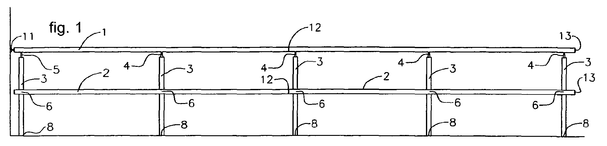
- Figure 1 shows a front elevation view of the railing of the invention, on a
horizontal plane, with incorporated upright pipe (3), handrail (1) and crosspiece
(2), ball joint (11) for distal wall fixing; a mixed ball joint (5), upper ball joint (4),
lower ball joint (6), simple cap (13), connection sleeve (12) and embedded anchor
(8).
- Figure 2 shows an elevation view of the profile of the railing of Figure 1.
- Figure 3 shows a perspective view of the railing of Figure 1.
- Figure 4 shows a front elevation view of the railing of the invention on an inclined
plane, a ramp; with incorporated upright pipe (3), handrail (1) and crosspiece (2),
upper ball joint (4), lower ball joint (6), simple cap (13), articulated foot (10) on a
ramp, and a simple upright (3) and horizontal base (7), each one on one end of the
ends of the ramp on the horizontal plane.
- Figure 5 shows a perspective view of the railing of Figure 4.
- Figure 6 shows a perspective view of the jointing of the upright (3) with the
handrail (1) by means of the upper ball joint (4).
- Figure 6.1 shows a perspective view similar to the previous one of an internally-profiled
open handrail (1a).
- Figure 6.2 shows a cross sectional view of the handrail (1) of the previous figure.
- Figure 7 shows a perspective view of the assembled upper ball joint (4)
intervening in Figure 6.
- Figure 7.1 shows a longitudinal sectional view of the assembled upper ball joint
(4).
- Figure 8 shows an exploded view of the disassembled upper ball joint (4) of
Figure 6.
- Figure 9 shows a perspective view of the jointing of the upright (3) with the
crosspiece (2) by means of the intermediate ball joint (6), not shown.
- Figure 9.1 shows a view similar to the previous one of the joint of the upright (3)
with the crosspiece (2a).
- Figure 10 shows a perspective view of the assembled intermediate ball joint (6)
intervening in Figure 9.
- Figure 11 shows an exploded view of the disassembled intermediate ball joint (6)
intervening in Figure 9.
- Figure 11.1 shows a longitudinally sectional view of the intermediate ball joint
(6).
- Figure 12 shows a perspective view of a horizontal simple upright (7) for fixing
on a surface.
- Figure 13 shows a view of Figure 12 with no fixings.
- Figure 14 shows a perspective view of a simple upright (38) for fixing on a
vertical surface.
- Figure 15 shows an exploded view of the simple upright (38) of Figure 14.
- Figure 16 shows a perspective view of the soleplate fixing of an upright (3) by
means of an embedded anchor.
- Figure 17 shows a perspective view of the assembled anchoring assembly (8) for
embedding of Figure 16.
- Figure 18 shows an exploded or disassembled view of the anchor (8) for
embedding of Figure 17.
- Figure 19 shows a perspective view of a soleplate fixing of the upright pipe (3) by
means of the articulated foot (10).
- Figure 20 shows a perspective view of the assembled articulated foot assembly
(10) of Figure 19.
- Figure 21 shows an exploded or disassembled view of the articulated foot
assembly (10) of Figure 20.
- Figure 22 shows a perspective view of a soleplate fixing of the upright pipe (3) by
means of a horizontal base (9).
- Figure 23 shows a perspective view of the assembled horizontal base assembly
(9).
- Figure 24 shows an exploded or disassembled view of the articulated foot
assembly (9) of Figure 23.
- Figure 25 shows a perspective view of a wall fixing of the upright pipe (3) by
means of the vertical foot (39).
- Figure 26 shows a perspective view of the assembled vertical foot (39) assembly.
- Figure 27 shows an exploded view of the disassembled vertical foot (39) assembly
of Figure 26.
- Figure 28 shows a perspective view of a jointing of pipes (1) and (3) by means of
a mixed ball joint (5).
- Figure 28.1 is similar to the previous figure showing a jointing of pipes (1a) and
(3) by means of a mixed ball joint (5).
- Figure 29 shows a perspective view of the assembled mixed ball joint (5).
- Figure 30 shows an exploded view of the disassembled mixed ball joint (5) of
Figure 28.
- Figure 31 shows a perspective view of the jointing of the upright (3) with the
handrail (1) and the wall fixing of the latter by means of a distal fixing ball joint
(11).
- Figure 32 shows a perspective view of the assembled distal ball joint (11).
- Figure 33 shows an exploded view of the assembled distal ball joint (11) of Figure
31.
- Figure 33.1 shows a sectional view of the sealed end of the distal ball joint (11).
- Figure 33.2 shows a sectional view of the anchoring disc (93) of the bent terminal
rod (92).
- Figure 34 shows a perspective view of the connection sleeve (12).
- Figure 35 shows a perspective view of the semi-assembled replacement sleeve
assembly (12A).
- Figure 36 shows an exploded view of the disassembled replacement sleeve (12A)
of Figure 35.
- Figure 37 shows a perspective view of the simple cap (13) assembly.
- Figure 38 shows an exploded view of the assembly projection of the simple cap
(13) of Figure 37.
- Figure 39 shows a perspective view of the assembled pressure cap assembly
(13A).
- Figure 40 shows an exploded view of the disassembled pressure cap (13A) of
Figure 39.
- Figure 40.1 shows a diametrical sectional view of the end (95).
- Figure 41 shows a perspective view of the assembly of the assembled stay tackle
(77) on the upright pipe (3).
- Figure 42 shows a perspective view of the disassembled stay tackle (77).
- Figure 43 shows a front elevational view of the threaded stay tackle (77) of Figure
42.
- Figure 44 shows a front elevational view of the profile of the threaded stay tackle
(77) of Figure 42.
- Figure 45 shows a plan view of the threaded stay tackle (77) of Figure 42.
- Figure 46 shows a perspective view of the assembly of the double screw (81) on
the upright pipe (3).
- Figure 47 shows a perspective view of the double screw (81).
- Figure 48 shows an elevational view of the screw (81) of Figure 47.
- Figure 49 shows a plan view of the screw (81) of Figure 47.
- Figure 50 shows a perspective view of a screwed fixing protection for pavement
screwing by means of a rivet (14) and security bolt (48).
- Figure 51 shows a semi-disassembled perspective view of Figure 50
- Figure 52 shows a perspective view of a security bolt (14).
- Figure 53 shows an elevational view of the security bolt (14) of Figure 52.
- Figure 54 shows a plan view of the security bolt (14) of Figure 52.
- Figure 55 shows a sectional view of the security bolt (14) of Figure 52.
- Figure 56 shows a perspective view of a security bolt (88).
- Figure 57 shows a perspective view of a perforated nut (89) for a security bolt
(88).
- Figure 58 shows a side elevational view of a structure integrated by a handrail
(1a), uprights (3) and supports (98-99).
- Figure 59 shows a profile view of the structure of Figure 58.
- Figure 60 shows a perspective view of the same structure of Figure 58.
- Figure 61 shows a view similar to Figure 58 of a structure with a crosspiece (2a).
- Figure 62 shows a view similar to Figure 59 of a structure with a crosspiece (2a).
- Figure 63 shows a view similar to Figure 58 of a structure with a crosspiece (2a).
-
PREFERRED EMBODIMENT OF THE INVENTION.-
-
In relation to said representations, a preferred embodiment of a barrier shown in
assembly examples is proposed, one example is on a horizontal plane (Figures 1,
2 and 3), and another one is on an inclined plane (Figures 4 and 5), and two more
examples with screened barriers on a horizontal or inclined plane and without a
crosspiece (Figures 58 or 60) or with it (Figures 61 to 63), wherein the
configuration and application of the various elements of the tubular structure
according to the idea of the invention can be seen, essentially; the tubular handrail
(1), crosspiece (2) and upright (3) elements; the alternative open elements or the
profile shaped elements (1a) and (2a); different ball joints (4, 6) of the tubular
elements; different fixing elements for fixing to the soleplate (8, 10) and to a wall
(11); connection sleeves (12) and other accessories.
-
Said handrail is constituted of a tubular metal handrail (1) and crosspieces (2) of a
round section, and two types of uprights, upright pipes (3) and simple uprights (7)
(Figures 12, 13, 14 and 15), the first uprights are provided with the suitable bore
holes (18 and 19) for allowing the jointing of the handrail (1) with the upright (3)
by means of the upper ball joint (4) (Figures 6, 7 and 8) or by means of the mixed
ball joint (5) (Figures 28, 29 and 30); and boreholes (20) for jointing the
crosspiece with the upright by means of the intermediate ball joint (6) (Figures 9,
10 and 11), and said railing being constituted of a handrail (1a) and crosspieces
(2a) (Figures 6.1, 6.2 and 9.1) susceptible to being assembled on uprights (3) or
(7) by means of the upper ball joint (4), the mixed ball joint (5) or the
intermediate ball joint (6).
-
The soleplate fixing of the upright pipes (3) can be carried out by means of the
embedded anchoring (8) (Figures 16, 17 and 18), or by means of screw-down feet
screwed on the surface, which in turn can be articulated feet (10) (Figures 19, 20
and 21), or simple bases (9), (Figures 22, 23, 24, 25, 26, and 27). The wall fixing
of the ends of the handrail is carried out by means of the distal ball joint (11)
(Figures 31, 32 and 33).
-
The longitudinal jointing of the tubular handrails and crosspieces is carried out by
means of the connection sleeve (12) (Figure 34), or also by means of the
replacement sleeve (12A) (Figures 35 and 36).
-
The finish or closure of the free ends of the handrails (1) (1a), crosspieces (2) (2a)
and vertical uprights (7) (Figures 15 and 27) can be resolved by means of the
simple cap (13) (Figures 37 and 38), or by means of the pressure cap (13A)
(Figures 39 and 40).
-
For the fixing of the cable terminals to the upright pipes (3, 7) provided with the
suitable boreholes, parts called a threaded stay tackle (77) (Figures 41, 42, 43, 44
and 45), and double screw (81) (Figures 46, 47, 48 and 49) are used.
-
For anti-theft protection of the screws for fixing to the ground (Figures 50 and
51), parts called security rivet (14) (Figures 52, 53, 54 and 55), and security bolt
(88) of Figure 56 are used.
-
The tubular handrail (1) provided with the suitable boreholes (18) or the open
handrail (1a) having an opening (1b) and internal reinforcements (1c) and (1d) are
jointed to or assembled on (Figures 6, 6.1, 6.2 and 8) the tubular upright (3),
producing a firm jointing between them by means of the upper ball joint (4)
(Figure 7), constituted of three blocks: the upper expansive action group (15)
housed inside the handrail pipe (1) (1a), the drive shaft (16) acting as a
transmission of the tightening force, and the lower pressing action group (17)
housed in the upright pipe (3), the total composition of which, shown in Figure 8,
consists of:
- Upper cap (21) having a basically semi-cylindrical composition with ends
provided with a semicircular groove (21a) for the coupling of a resilient
ring (24), with an also semi-cylindrical internal cavity (21 b) provided for
the housing of the cylindrical core (22), and another semi-frustoconical
cavity (21 c) for allowing the housing of the positioning and removal tool.
- A cylindrical-shaped core (22) provided with a threaded perforation (22a)
having an axis perpendicular to the cylinder of the core (22).
- A lower cap (23) basically shaped like the upper cap but also provided with a
through perforation and channel (23c) which, at the moment of installation,
must be accessible from the perforation (18) made on the pipe of the handrail
(1), and which, together with the upper cap (21), forms a cylindrical cavity for
the housing of the core (22), such that once the entire assembly is assembled,
the threaded perforation (22a) of the core (22), the channel (23c) and the
perforation (19) of the pipe (1) are aligned, and another frustoconical cavity
(21 c-23d) in an axial direction for the housing of the positioning and removal
tool.
- A resilient o-ring (24) keeping the upper group (15) assembled at the time of
assembly.
- The drive shaft (16) is a basically cylindrically-shaped part (25) having a
frustoconical thickening (25b) in the central area provided with a hole (25c)
for allowing the interlocking of the assembly wrench by means of which the
rotational force is applied to the former and the penetration of its two ends
which are shaped like screws (25a and 25e), both inversely threaded with
regard to one another, occurs. The upper threaded screw or rod shaped end
(25a) penetrates through the perforation (18) existing on the handrail pipe (1)
and the channel of the lower cap (23), and is screwed into the core (22) of the
upper expansive action group (15), then the separation of the caps (21) and
(23) and the interlocking effect occurring due to pressure of the assembly (15).
The lower end (25d) is a cylindrical rod which is made up of two spans, one
smooth span, starting from the base of the frustoconical body, and another
more distal span (25e) constituting the lower end of the part, having a smaller
section and thread, and passes through the cap (26) and through the assembly
of elements making up the lower compressing action group (17) to be screwed
down in the last element of this assembly, the lower press (29), and to cause
the compression of the resilient ring (28) necessary for achieving the finn
assembly of the assembly (17) inside the upper end of the upright pipe (3).
- The cap (26) is a basically cylindrical-shaped part having a thickening at its
lower base acting as a stop (26a) and which is provided with a cylindrical
perforation (26b) to allow the passage of the lower rod (25d) of the drive shaft
(25) and to act as a seating at the base of the frustoconical body (25b) of the
same part.
- An upper press (27) or cylindrical disc provided with a perimetral recess (27a)
to house the resilient ring (28) and with a cylindrical perforation (27b) to
allow the passage of the threaded span of the lower rod (25d) of the drive shaft
(25). This part also acts as a seating or stop for the smooth cylindrical span
(25d) of larger diameter of the lower rod of the drive shaft (25).
- A resilient ring (28) constituted of a tubing of rubber or of any other material
of similar resilient properties which, upon being compressed by the presses
(27) and (29) by means of the rotation of the drive shaft (25), is forced to
develop a volume in diameter that exceeds that of the pipe (3) and causes an
interlocking due to very resistant friction.
- A lower press (29) or disc having a perimetral recess (29a) for housing the
resilient ring (28) and provided with a threaded borehole (29b) provided for
screwing in the threaded lower end (25e) of the drive shaft (25).
-
The tubular crosspieces (2), provided with suitable boreholes (19) or open
crosspieces (2a), are jointed or assembled (Figures 9 and 9.1) on the tubular
upright (3), also provided with suitable boreholes (20), by means of the
intermediate ball joint (6) (Figure 10), causing a strong jointing, the composition
of which, shown in Figure 11, is constituted of:
- A stud bolt (30) or threaded cylinder fixing the reinforcing block (31) in the
suitable position inside the pipe (2a), such that the threaded perforation of the
latter (31b) and (19) of the pipe (2a) are kept in alignment at the time of
assembly.
- The reinforcing bloc (31) is a regular prism having through perforations (31a)
and (31b) along its two axes of symmetry, each one of them with features
adjusted to their function with regard to diameter, length, internal surface type,
smooth or threaded, or the like. The axial perforation (31a) allows the
coupling of the positioning tool at the time of assembly, and the transverse
perforation (31b) divided into two inversely threaded spans with regard to one
another allows the housing of the threaded rod (32c) of the drawbolt (32) in
one of its spans and the housing of the corresponding positioning stud bolt,
with right-hand thread (30) or left-hand thread (33), in the other span.
- A drawbolt (32), constituted of a double screw with a thickening in the central
portion (32a) and two threaded spans (32c) and (32d) in an inverse direction in
each one of the threaded spans with regard to the other one. In the central
thickening, there is a cavity (32b) for allowing the interlocking of a tool or
wrench facilitating the assembly and tightening operation by means of a
rotational movement.
- A left-hand stud bolt (33) or cylinder threaded to the left fixing the
reinforcement block (31) in the suitable position inside the pipe, such that the
threaded perforation of the latter (31 b) and (20) of the pipe (3) are kept in
alignment at the time of assembly.
-
Mixed ball joints can also be carried out (Figure 28) for jointing the handrail (1)
to the upright pipes (3) by means of the mixed ball joint (5) of Figure 29, which is
obtained by combining, according to that shown in Figure 30, parts (25), (26),
(27), (28) and (29) of the upper ball joint (4) with parts (30) and (31) of the
intermediate ball joint (6).
-
The mixed ball joint (5) is especially useful for reinforcing the fixing to a wall of
the end of a pipe in a horizontal position, either the crosspiece (2) or handrail (1),
by means of the distal fixing ball joint (11) (Figure 32), producing a strong
jointing (Figure 31), the composition of which, shown in Figure 33 is constituted
of the already described parts called reinforcing block (31) and stud bolt (30), the
drive shaft (25) and those parts making up the lower group (26), (27), (28) and
(29).
-
The most typical upright of the invention is the upright pipe (3) simply constituted
of a pipe provided with suitable perforations (20) for allowing the jointing with
the crosspiece (2) or fixing of the cable terminals to the wall uprights (7) (Figures
14 and 15); but there are other upright models, such as the horizontal simple
upright (7) (Figures 12 and 13), made up of an upright pipe (34b) welded to an
anchoring plate (34a), also provided with suitable perforations (37) for the fixing
thereof to a soleplate, and the simple vertical upright (7) (Figures 14 and 15) made
up of an upright pipe equal to the previous one, but of greater lengths (36, 38),
welded to its anchoring plate (39) by means of pins (41), all this arranged and
provided with boreholes (40) for the fixing thereof in a vertical position and
parallel to the wall by means of screws protected with rivets (14) (Figure 52), and
finished at the lower end with a simple cap (42) (Figure 38).
-
The fixing (8) embedded in the soleplate and at the same time demountable from
upright pipes (3) is solved by means of the anchoring embedded in the soleplate of
Figure 16, an assembly of parts (45) (Figure 17), basically constituted according
to Figure 18 of two concentric pipes (46) and (47), of different diameters and
lengths, the larger one inserted in the small one and welded together at a certain
height, leaving a passage or separation between both that is sufficient for allowing
the housing by way of insertion of the lower end of the upright pipe. For the
interlocking of the anchoring with the soleplate, the pipe (47) is provided with an
anchoring element (48) welded on its lower end. The firm interlocking of the
upright pipe (3) with the embedded foot (45) is achieved by means of a pressing
action system already described above made up by elements (27), (28) and (29)
which achieves the firm fixing by means of the tightening of a conventional Allen
screw (49).
-
The demountable fixing of an upright pipe (3) on a very inclined surface (10) can
be carried out by means of the articulated foot (Figure 19), consisting of an
assembly of parts (Figure 20), constituted according to Figure 21 of:
- The anchoring base (50) is a body made up of two volumes, one in the form of
a plate (52) provided with suitable perforations (51) for allowing the passage
of the anchoring screws and the access to the threaded end of the screw (65)
of the pressing assembly, and another volume in the form of a spherical cap
(53) in turn provided with a groove (54) allowing the passage of the pressing
screw (65) in an arc that is sufficiently broad to allow different positions of
the conical-cylindrical arm (55) in order to thus form the necessary
articulation for enabling the adaptation to the slope of the plane or ground on
which the railing is installed.
- The conical-cylindrical arm (55) is a hollow body, basically made up of two
volumes: one volume (57), situated at the base or lower portion of the part, is
frustoconical, hollow and with a beveled or countersunk profiled base, and
the other volume (56), at the upper portion of the part, is a tubular cylindrical
volume. The frustoconical portion of the part is that which articulates and
rests on the cap (53) of the anchoring base (50), and the tubular cylindrical
portion is provided for being housed inside the upright pipe (3) and at its
upper end is a support for the pressing assembly by means of the welded
jointing of the lower press (58), the configuration of this part being a disc
having a perimetral recess (58a) for housing the resilient ring (28) and
provided with a threaded borehole (58b) provided for screwing down the
lower threaded end of the pulling screw (65).
- A resilient ring (28) constituted of a tubing of rubber or of any other material
of similar resilient features which, forced by means of compression to
develop a diameter size exceeding that of the inside of the pipe, produces
very resistant interlocking due to friction.
- A hollow cylindrical sleeve (61) for allowing the passage of the pulling screw
(65) and adjusting the pressure of the resilient ring (28), limiting the run of
the upper press (62).
- An upper press (62) or cylindrical disc provided with a perimetral recess (62a)
for housing the resilient ring (28) and with a cylindrical perforation (62b) for
allowing passage and acting as a stop for the head of the pulling screw (65).
- A pulling screw (65) constituted of a conventional Allen screw is screwed into
the lower press (58) and exerts pressure on the upper press (62), causing these
two parts to approach one another, compressing the resilient ring (28).
-
The demountable fixing of an upright pipe (3) on a horizontal surface (9) can be
carried out by means of the horizontal foot (Figure 22) consisting of an assembly
of parts (Figure 23) constituted according to Figure 24 by:
- An anchoring group (35) which is a body made up of three welded elements
(35a), (35b) and (29), the first one in the form of a plate (35a) provided with
suitable perforations (37) for allowing the passage of anchoring screws; the
second one (35b) in the form of a pipe, provided for being housed inside the
upright pipe (3) and joined by means of welding at its upper end to the third
element (29) which is a base of the pressing assembly.
- A lower press (29) or disc having a perimetral recess (29a) for housing the
resilient ring (28) and provided with a threaded borehole (29b) provided for
screwing the threaded lower end (25e) of the pulling screw (49).
- An upper press (27) or cylindrical disc provided with a perimetral recess (27a)
for housing the resilient ring (28) and with a cylindrical perforation (27b) to
allow the passage of the pulling screw (49).
- A resilient ring (28) constituted of a tubing of rubber or of any other material
of similar resilient properties which, compressed by the presses (27) and (29)
by means of the rotation of the screw (49), is forced to develop a diameter size
exceeding that of the pipe (3), causing an interlocking due to very resistant
friction.
-
A pulling screw (49) constituted of a conventional Allen screw screwed into the
lower press (29) and exerting pressure on the upper press (27), causing these two
parts to approach one another, compressing the resilient ring (28).
-
The demountable fixing of an upright pipe (3) on a vertical surface can be carried
out by means of the vertical foot (Figure 25) consisting of an assembly of parts
(Figure 26) constituted according to Figure 27 by:
- An anchoring plate (39) provided with suitable perforations (40) for allowing
the passage of anchoring screws.
- Pins (41) welded to the anchoring plate and to the fixing pipe (67).
- A fixing pipe (67) welded to the pins and provided with a span (68) of smaller
outer diameter provided for being housed inside the upright pipe (3) and
joined by means of welding at its upper end to the disc (29) acting as the
lower press of the pressing assembly.
- A lower press (29) or disc having a perimetral recess (29a) for housing the
resilient ring (28) and provided with a threaded borehole (29b) provided for
screwing the threaded lower end of the pulling screw (49).
- An upper press (27) or cylindrical disc provided with a perimetral recess (27a)
for housing the resilient ring (28) and with a cylindrical perforation (27b) to
allow the passage of the pulling screw (49).
- A resilient ring (28) constituted of a tubing of rubber or of any other material
of similar resilient properties which, compressed by the presses (27) and (29)
by means of the rotation of the screw (49), is forced to develop a diameter size
exceeding that of the inside of the pipe (3), causing an interlocking due to very
resistant friction.
- A pulling screw (49) constituted of a conventional Allen screw screwed into
the lower press (29) and exerting pressure on the upper press (27), causing
these two parts to approach one another, compressing the resilient ring (28).
- A simple cap (42) housed by pressure in the lower end of the fixing pipe (67),
which is described below in Figure 38.
-
The demountable fixing of the end of a pipe in a horizontal position (1) on a
vertical surface can be carried out by means of the combination of the mixed ball
joint (5) already described above and the distal fixing ball joint (11) (Figure 31),
consisting of an assembly of parts (Figure 32), constituted by the following
specific elements according to Figure 33:
- A sealed end (91) basically constituted of a cylindrical volume, the upper base
of which has a slightly enlarged perimetral edge (91 b) acting as a stop during
the operation of introducing the terminal into the pipe (1) on which it is
installed, this base therefore being positioned as an outer cap. The cylinder is
further provided with a perimetral channel (91c) for the housing of the o-ring
pressure seal and with a perforation (91a) in an axial direction which is
divided into two spans of different diameters. The smaller section span is also
threaded and it is the one closest to the lower base of the cylinder.
- An arm (92) formed by a rod of a cylindrical section and bent at an angle,
having three spans of different configurations. The end of the short side is
threaded (92a) to allow the assembly with the anchoring disc (93), and the end
of the longest side is also threaded (92b) for the purpose of allowing the
assembly with the sealed end (91) and with the reinforcing block (31) of the
mixed ball joint (5).
- A disc (93) provided with an axial perforation (93a) for allowing the passage
of fixing screws to a wall and with another transverse threaded perforation
(93b) to allow the assembly of the arm (92).
-
For the longitudinal connection or jointing of pipers, there are two basic elements,
the simple connection sleeve (Figure 34) and the replacement sleeve (Figure 35).
-
The simple connection sleeve (12) of Figure 34 is basically constituted of a pipe
(69) provided with a noticeable slight central thickening (71) in the form of an
annular rib, and the entire outer surface (70) having a near smooth appearance is
micro-threaded.
-
The replacement sleeve (12A) (Figure 35) incorporates a special interlocking
device, similar to the so-called "lower pressing action group", made up of parts
(27), (28), (29) and (49), already described above, combined with the following
parts shown in Figure 36:
- A movable sleeve (72) made up of a circular section pipe and an internal
transverse wall (73) perforated (78) for the purpose of allowing the passage
and acting as a stop for the screw (49) and its washer (XX).
- A spring or device (74) allowing the moving of the sleeve (72) once
introduced in the pipe to be connected.
- A pipe-like bead (75) for adjusting the pressure of the pressing action group
and acting as a shaft for the spring (74), a channel for the screw (49) and as a
guide and stop for the run of the wall (73) of the movable sleeve (72).
-
The finishing caps for pipes can be simple or pressure caps.
-
The simple cap (13) (Figure 37) is an assembly according to that described in
Figure 38, of two parts, one basically cylindrical metal part (42) housed tightly
inside the tubular elements of the system, and having a thickening at one of the
bases (42a) in order to act as a stop and outer finishing, and the cylindrical portion
intended for being housed inside the pipes is provided with a half round groove
(42b) for housing the other element of the assembly, an o-ring (44), providing
pressure to the assembly, thus producing a strong and sealed finish.
-
The pressure cap (13A) (Figure 39) is formed by elements (27), (28) and (29)
already described in the "lower pressing action assembly", and by other specific
elements shown in Figure 40:
- An internal sleeve (94) made up of a circular section pipe which is placed
between parts (27) and (95) and allows the passage for the fixing screw (96).
- An outer terminal (95) formed by a basically cylindrically shaped disc having
a thickening (95c) at its lower base or cap (95a) for acting as a stop and which
is provided with a cylindrical perforation (95b) on two spans of different
diameters provided for allowing the passage of the fixing screw (96) and for
housing the head (96a)
-
The special accessories incorporated by the system for fixing the cable terminals
to the upright pipes are the threaded stay tackle (77) (Figures 41, 42, 43, 44 and
45) and double screw (81) (Figures 46, 47, 48 and 49).
-
The threaded stay tackle (77) consists of a single-body part made up of two
volumes with a common shaft, one volume corresponding to the cylindrical rod
(80) with a threaded surface, and the other volume corresponding to the head (78)
with a smooth surface integrated by a mixed prism of four symmetrically arranged
sides: two sides with a flat surface and parallel to one another, and the other two
sides with a curved-convex surface. The head has a transverse circular through
hole (79) on the lateral sides with a flat surface. The base of the prism
corresponding to the head is a flat surface constituted of a four-sided polygon,
formed by two straight lines and parallel to one another, cutting two other curved
lines also in a symmetrical position with regard to one another.
-
The double screw (81) consists of a single-body part made up of two cylindrical
volumes with a threaded outer surface, both volumes with a common shaft but
different diameter and height, one volume being the rod (83) and the other one
being the head (84), the latter having a hexagonal cavity (82) open from its outer
base.
-
Both the stay tackle (77) and double screw (81) are intended for being secured in
a corresponding perforation (76) for the anchoring of cables or crosspieces
assembled on the uprights (3), (7).
-
For the anti-theft protection of the fixing screws to the ground (Figures 50 and
51), parts called security rivet (14) (Figures 52, 53, 54 and 55), security bolt (88)
(Figure 56) and nut (89) with a transverse perforation (90) (Figure 56), are used.
-
The security rivet (14) is a metal protector constituted of a single semi-spherical
body of a circular base and outer elevation that is noticeably flattened, generated
by the revolution of a continuous curved line without vertices, made up of three
arcs of different radii joined at the point of tangency, the part also having an inner
cavity (85) open at the base, of a cylindrical shape, a slightly vaulted bottom and
an entrance (85) grooved by means of an also cylindrical cavity,, of limited height
and beveled vertices (87).
-
According to Figure 51 the rivet interlocks by means of pressure on commonly
used hexagonal nuts (89) producing the jointing of both parts by deformation,
being impossible to separate them without destroying them. The rivet (14) acts as
a clinch of the mechanical joint while at the same time hiding the nut (89) and
preventing operation thereon. In order for the nut (89) and rivet (14) assembly to
provide complete anti-theft security, the nut must be locked prior to the riveting or
rivet assembly operation by means of a commonly used security bolt (88) which is
introduced in a transverse perforation (90) carried out on the nut for that purpose.
-
An urban barrier solution of those constituted of an open tubular railing (1a) or by
an open tubular crosspiece (2a) of the type shown in Figures 6.1 and 6.2, and in
this case provided with screen protection or glass partition (97), in a first version
according to figures 58, 59 and 60, with an open tubular railing (a1), on the profile
of which the upper edge of the screen or glass (97) is housed, and on the lower
edge of which they are secured by staples (98 and 99) in their respective ends and,
in a second version, shown in Figures 61, 62 and 63, of barriers completed with
crosspieces (2a).