Technical Field
The present invention relates to a transferring
and molding method and transferring and molding apparatus,
which places a transfer film between dies and transfers a
pattern provided on the transfer film onto a molded
article concurrently with molding.
Background Art
The transferring and molding apparatus
disclosed in Japanese Examined Patent Publication No. 01-59095
is known.
This transferring and molding apparatus
includes a movable die mounted on a movable platen, a
stationary die mounted on a stationary platen, an
injection nozzle, a transfer film, a film feeding unit
mounted above the movable platen so as to move in a
widthwise direction of the transfer film, a film winding
unit mounted below the movable platen so as to move in a
widthwise direction of the transfer film, and a position
detecting unit for the transfer film.
The transfer film is moved in a lengthwise
direction with the dies opened, and stopped at the
transfer position when the position detecting unit has
detected the position of the transfer film, after which a
molten resin is injected from the injection nozzle with
the dies closed so as to hold the transfer film
therebetween, to transfer the pattern provided on the
transfer film onto a molded article concurrently with the
molding, and to thereby produce a molded article having
the pattern transferred from the transfer film at a
predetermined position.
In the aforementioned transferring and molding
apparatus, the transfer film is positioned in the
transfer position as follows.
More specifically, the position detecting unit
is provided including a lengthwise direction sensor that
detects a lengthwise direction mark of the transfer film,
and a first and a second widthwise direction sensors that
detect a widthwise direction mark of the transfer film,
all of which are optical sensors. For the lengthwise
positioning, the transfer film is moved lengthwise until
the lengthwise direction sensor detects the lengthwise
direction mark of the transfer film, at which point the
film feeding unit and the film winding unit stop the
movement of the transfer film.
For the widthwise positioning, the film feeding
unit is moved widthwise with respect to the transfer film
until the first widthwise direction sensor detects the
widthwise direction mark of the transfer film, and the
film winding unit is moved widthwise with respect to the
transfer film until the second widthwise direction sensor
detects the widthwise direction mark of the film, and
once the first and the second widthwise direction sensors
have detected the widthwise direction mark, the film
feeding unit and the film winding unit are stopped.
That is, the transferring and molding method
with the transferring and molding apparatus is a method
for repeating the transferring and molding processes of
positioning the transfer film in the transfer position by
moving the transfer film in the die open state,
thereafter placing the transfer film in the die closed
state and then injecting the molten resin into the cavity
for the transfer of the pattern of the transfer film in
the prescribed position of the molded article
concurrently with molding.
The conventional transferring and molding
method has a process for positioning the transfer film in
the transfer position so as to make the pattern of the
transfer film position face the prescribed position of
the die (molding section). Even through this process,
the pattern transferred onto the molded article is
sometimes shifted as a consequence of repetitively
carrying out the aforementioned transferring and molding
process.
For example, when wrinkles occur on the
transfer film during the transferring and molding, a
pattern shift occurs. The wrinkles of the transfer film
are prominently created especially when the configuration
of the molded article is bent in a convex shape in
placing the transfer film between the dies or when a
plurality of molding sections are formed on the die.
As described above, since the positioning of
the transfer film is performed based on the position of
the lengthwise direction mark and widthwise direction
mark provided on the transfer film in the conventional
transferring and molding method, the position of the
transferred pattern is often shifted while repeating the
transferring and molding process. Such a position shift
can be corrected by correcting the transfer position for
the transfer film, however the transferring and molding
process has to be suspended for the repositioning of the
transfer film.
The present invention is made in view of the
aforementioned problems, and the object thereof is to
provide a transferring and molding method and transferring
and molding apparatus capable of producing a molded article
on which a pattern is transferred in a prescribed
position by automatically correcting the position of a
transfer film when there is produced a molded article on
which the transferred pattern is shifted.
Disclosure Of Invention
According to a first aspect of the present
invention, there is provided a transferring and molding
method comprising:
According to a second aspect of the present
invention, there is provided the transferring and molding
method as defined in the first aspect, further comprising:
According to a third aspect of the present
invention, there is provided the transferring and molding
method as defined in the first aspect, further comprising:
According to a fourth aspect of the present
invention, there is provided the transferring and molding
method as defined in one of the first aspect to the third
aspect, further comprising:
According to a fifth aspect of the present
invention, there is provided a transferring and molding
apparatus comprising:
wherein the transfer film is moved in at least
one of a lengthwise direction and a widthwise direction
of the transfer film by the transfer film moving section
based on a value and a direction to be corrected which
are obtained from both the first and second digital
values.
According to a sixth aspect of the present
invention, there is provided the transferring and molding
apparatus as defined in the fifth aspect, further
comprising:
According to a seventh aspect of the present
invention, there is provided the transferring and molding
apparatus as defined in the fifth aspect, further
comprising:
According to a eighth aspect of the present
invention, there is provided the transferring and molding
apparatus as defined in the fifth aspect, further
comprising:
According to a ninth aspect of the present
invention, there is provided the transferring and molding
apparatus as defined in one of the fifth aspect to eighth
aspect, further comprising:
According to a tenth aspect of the present
invention, there is provided the transferring and molding
apparatus as defined in the fifth aspect, further
comprising:
wherein the transfer film is moved based on the
value and the direction to be corrected with respect to
the transfer position of the transfer film obtained from
the average value and the second digital value.
According to the present invention, when the
pattern of the molded article is shifted, the transfer film
is automatically moved by the shift dimension in the
opposite direction to the shift direction. Therefore, the
pattern is transferred at the predetermined position on the
molded article b that subsequently undergoes the
transferring and molding process.
Consequently, when a molded article on which
the position of the transferred pattern is shifted is
produced, the position of the transfer film is
automatically corrected so that the pattern is
transferred at the predetermined position, which
eliminates the need to suspend the transferring and
molding process and maintains high accuracy in
positioning of the pattern to be transferred onto the
molded article.
Further, according to the present invention,
the shift is detected again after the positional
correction of the transfer film, and the positional
correction is repeated again when there is a shift
outside the tolerance range. Therefore, the position of
the transfer film can be corrected into the tolerance
range, by performing the transferring and molding process
after the positional correction.
Further, since the transfer position of the
pattern is only slightly different among the molded
articles produced through successive transferring and
molding process, it is possible to store the first
digital value and to perform the positional correction of
the transfer film based on an average value thereof, thus
to correct the position shift of the pattern in high
accuracy over an entirety of the successive transferring
and molding process.
Brief Description Of Drawings
These and other aspects and features of the
present invention will become clear from the following
description taken in conjunction with the preferred
embodiments thereof with reference to the accompanying
drawings, in which:
Best Mode for Carrying Out the Invention
Before proceeding with the description of the
present invention, it is to be noted that same components
are given identical reference numerals throughout the
accompanying drawings.
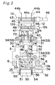
As shown in Figs. 1 and 2, an injection molding
section 100 includes a stationary die 2 mounted on a
stationary platen 1, a movable die 4 mounted on a movable
platen 3, and an injection nozzle 5 for injecting a
molten resin into a cavity defined by the dies.
In this embodiment, the stationary platen 1 is
fixed to a base plate 6, and the movable platen 3 is
guided so as to contact or separate from the stationary
platen 1, by four tie bars 7 fixed to the stationary
platen 1.
By moving the movable platen 3, a parting
surface 2a of the stationary die 2 and the parting
surface 4a of the movable die 4 are brought in pressure
contact with each other so as to be put into a die closed
state in which the cavity is defined by molding sections
of the dies (a molding section 2b of the stationary die 2
and a molding section 4b of the movable die 4) and a die
open state in which the parting surfaces 2a and 4a are
separated from each other.
Also, although the cavity is basically formed
by the stationary die 2 and the movable die 4 in the
injection molding section 100, an additional member such
as an intermediate plate may be employed.
A film feeding unit 10 and a film winding unit
11 mounted on the movable platen 3 constitute a film
moving section for moving the transfer film 20 with
respect to a parting surface 4a of the movable die 4
(i.e., moving the transfer film 20 in the lengthwise
direction of the film).
The transfer film 20 is moved in parallel to
the parting surface 4a of the movable die 4, with a
spacing therefrom.
The film feeding unit 10 and the film winding
unit 11 are disposed so as to move in a direction
perpendicular to the moving direction of the movable die
4 (i.e., in the widthwise direction of the transfer film
20), carried by a first movement mechanism 12 and a
second movement mechanism 13, respectively. In other
words, the film feeding unit 10 and the film winding unit
11 are activated in the widthwise direction of the film
by the first movement mechanism 12 and the second
movement mechanism 13, thus to constitute a film moving
section which moves the transfer film 20 in the widthwise
direction thereof.
In this embodiment, the film feeding unit 10 is
mounted above the movable platen 3, and the transfer film
20 is moved in the widthwise direction by the first
movement mechanism 12.
The film winding unit 11 is provided with a
film tension mechanism 14 mounted below the movable
platen 3 and a film winding mechanism 15 mounted on the
baseplate 6, and the film tension mechanism 14 is moved
in the widthwise direction of the transfer film 20 by the
second movement mechanism 13.
The transfer film 20 is separated from the
parting surface 4a of the movable die 4 and moved so as
to become parallel to the surface.
Without limitation to the above arrangement, it
is acceptable to mount the film feeding unit 10 below or
on a lateral side portion of the movable platen 3 and
mount the film winding unit 11 above or on the other
lateral side of the movable platen 3 or to mount the film
feeding unit 10 and the film winding unit 11 on the
baseplate 6 or the stationary platen 1.
Accordingly, the film moving section can move
the transfer film 20 in the lengthwise direction with
respect to the die parting surface, before performing the
transferring and molding process, and preferably in the
widthwise direction with respect to the die parting
surface (with respect to the parting surface 2a of the
stationary die 2 or the parting surface 4a of the movable
die 4) during the transferring and molding, and the
transfer film 20 can be moved at least one of the
lengthwise direction and the widthwise direction during
the positional correction of the transfer film 20
described later.
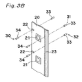
The transfer film will now be described. As
shown in Figs. 3A and 3B, the transfer film 20 has a
plurality of patterns 21 longitudinally aligned on a
surface of a base film 20a, with an interval. Since the
pattern 21 is released from the base film 20a to be
transferred to the molded article in the molding process
performed in the injection molding section 100, the
transfer film 20 includes a release protection layer 20b
provided on the base film 20a, on which a pattern ink
layer 20c constituting the pattern is provided. Also, on
the pattern ink layer 20c an adhesive layer 20d is
provided, so that the adhesive layer 20d adheres to the
molten resin upon contacting the same when executing the
injection molding, and thereby the pattern ink layer 20c
is separated from the base film together with the release
protection layer 20b, thus to be transferred onto the
molded article.
The pattern 21 provided on the transfer film 20
is not limited to a print pattern, but a metal deposition
layer may be employed so as to constitute the pattern ink
layer 20c.
The pattern ink layer 20c may be any one of
patterns, characters, symbols and so on used for the
conventional transfer films, including a combination of a
metal deposition layer and a print pattern.
As shown in Fig. 3B, the transfer film 20 is
also provided with a lengthwise direction mark 22 and a
widthwise direction mark 23, which serve for detection of
the position of the transfer film 20 when the pattern 21
is transferred onto the molded article concurrently with
the molding, i.e. the transfer position of the transfer
film 20.
As shown in Fig. 3B, the lengthwise direction
mark 22 (3mm in width) provided at intervals on one side
in the widthwise direction of the transfer film 20, and
the widthwise direction marks 23 (3mm in detecting width)
is continuously provided on the other side in the
lengthwise direction.
Although the transfer film 20 is transparent
and the marks 22 and 23 are nontransparent in this
embodiment, the marks 22 and 23 may be translucent.
Moreover, it is acceptable that the transfer film 20 is
nontransparent or translucent and the marks 22 and 23 are
transparent.
This position detecting unit for the transfer
film is provided with a lengthwise direction sensor 30
and first and second widthwise direction sensors 31, 32
attached to the die, as shown in Figs. 1 and 2, to be
used to detect the marks 22, 23 of the transfer film, and
hence the position of the transfer film.
An example of each sensor will be described.
As shown in Figs. 1 and 2, the lengthwise
direction sensor 30 and the widthwise direction sensors,
such as the first and the second widthwise direction
sensors 31, 32, are located close to the die, for example
the movable die 4. It is to be noted that it is not
always necessary to provide two widthwise sensors', but
just one, or three or more widthwise direction sensors
may be provided.
The lengthwise direction sensor 30 is mounted
on one side in the widthwise direction a little closer to
the upper portion of the movable die 4. The first
widthwise direction sensor 31 is mounted on the other
side in the widthwise direction a little closer to the
upper portion of the movable die 4, and the second
widthwise direction sensor 32 is mounted on the other
side in the widthwise direction a little closer to the
lower portion of the movable die 4.
The lengthwise direction sensor 30 and the
first and second widthwise direction sensors 31 and 32
detect the lengthwise direction mark 22 and the widthwise
direction mark 23, respectively, of the transfer film 20
and detect the amounts of shift with respect to the
respective marks.
For example, the sensors are each constituted
of a laser line sensor (detecting width 3mm), and
provided with a light emitter 33 and a light detector 34.
The light emitter 33 and the light detector 34 are
located on both sides in the thickness direction of the
transfer film 20 as shown in Fig. 3. Light from the
light emitter 33 is received by the light detector 34
through the transfer film 20.
The lengthwise direction sensor 30 is oriented
such that an extension thereof is aligned with the
lengthwise direction of the transfer film, and the size
(size in the lengthwise direction of the film) of light
from the light emitter 33 of the lengthwise direction
sensor 30 is generally equal to the size (size in the
lengthwise direction of the film) of the lengthwise
direction mark 22. The first and the second widthwise
direction sensors 31, 32 are oriented such that an
extension thereof is aligned with the widthwise direction
of the transfer film, and the size (width) of light from
the light emitter 33 of each of the first and second
widthwise direction sensors 31 and 32 is generally equal
to the size (width) of the widthwise direction mark 23.
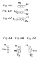
With this arrangement, in the case where the
lengthwise direction mark 22 and the lengthwise direction
sensor 30 coincide with each other when the transfer film
20 is located in the transfer position, the light 33a of
the light emitter 33 is completely interrupted by the
lengthwise direction mark 22 as shown in Fig. 4A, and the
quantity of light received by the light detector 34 is
zero.
In the case where the lengthwise direction mark
22 goes beyond the lengthwise direction sensor 30 when
the transfer film 20 is located in the transfer position,
the light 33a of the light emitter 33 is shifted upward
with respect to the lengthwise direction mark 22 as shown
in Fig. 4B, and the light detector 34 receives the light
of the quantity corresponding to the amount of shift S1.
Therefore, a shielding ratio of the mark with respect to
the light detector 34 can be detected from the quantity
of the received light.
In the case where the lengthwise direction mark
22 falls short of the lengthwise direction sensor 30 when
the transfer film 20 is located in the transfer position,
the light 33a of the light emitter 33 is shifted downward
with respect to the lengthwise direction mark 22 as shown
in Fig. 4C, and the light detector 34 receives light
corresponding in quantity to the amount of shift S2.
Therefore, a shielding ratio of the mark with respect to
the light detector 34 can be detected from the quantity
of the received light.
In the state shown in Figs. 4B and 4C, the
lengthwise position of the transfer film can be detected
based on the shielding ratio of the mark 22 with respect
to the light detector 34. Also, keeping the historic
record of the shielding ratio of the light detector 34
while the transfer film moves in the lengthwise direction
allows detecting the shift direction of the transfer film.
Specifically, in the transferring and molding
apparatus shown in Fig. 1, since the transfer film is
moved downward from an upper position, the magnitude of
S2 shown in Fig. 4C gradually becomes smaller, by which
the shielding ratio of the light detector 34 gradually
increases, until reaching the maximum in the state shown
in Fig. 4A, and when the lengthwise direction mark 22
moves further downward to reach the state shown in Fig.
4B, the magnitude of S1 gradually becomes larger with the
movement of the mark, by which the shielding ratio of the
light detector 34 gradually decreases.
Detecting thus the positional relation between
the lengthwise direction sensor 30 constituted of a laser
line sensor and the lengthwise position of the mark leads
to detecting the shift dimension and shift direction of
the transfer film in the lengthwise direction. Therefore,
the lengthwise direction sensor 30 is the sensor section
that detects the transfer position in the lengthwise
direction of the transfer film 20 as a digital value.
In the case where the widthwise direction mark
23 coincides with the first widthwise direction sensor 31
when the transfer film 20 is located in the transfer
position, the light 33a of the light emitter 33 is
completely interrupted by the widthwise direction mark 23
as shown in Fig. 5A, and the quantity of light received
by the light detector 34 is zero.
In the case where the widthwise direction mark
23 is shifted to one side in the widthwise direction with
respect to the first widthwise direction sensor 31 when
the transfer film 20 is located in the transfer position,
the light 33a of the light emitter 33 is shifted to the
other side in the widthwise direction of the widthwise
direction mark 23 as shown in Fig. 5B, and the light
detector 34 receives light of the quantity of received
light corresponding to the amount of shift S3. Therefore,
a shielding ratio of the mark with respect to the light
detector 34 can be detected from the quantity of the
received light.
In the case where the widthwise direction mark
23 is shifted to the other side in the widthwise
direction with respect to the first widthwise direction
sensor 31 when the transfer film 20 is located in the
transfer position, the light 33a of the light emitter 33
is shifted to the one side in the widthwise direction of
the widthwise direction mark 23 as shown in Fig. 5C, and
the light detector 34 receives light of the quantity of
received light corresponding to the amount of shift S4.
Therefore, a shielding ratio of the mark with respect to
the light detector 34 can be detected from the quantity
of the received light.
In the state shown in Figs. 5B and 5C, the
widthwise position of the transfer film can be detected
based on the shielding ratio of the mark 23 with respect
to the light detector 34. Also, keeping the historic
record of the shielding ratio of the light detector 34
while the transfer film moves in the widthwise direction
allows detecting the shift direction of the transfer film.
The same applies to the positional relation
between the second widthwise direction sensor 32 and the
widthwise direction mark 23, and the position of the
widthwise direction mark 23 can be measured by the second
widthwise direction sensor 32.
Consequently, detecting the positional relation
between the first and the second widthwise direction
sensors 31, 32 constituted of laser line sensors and the
widthwise position of the mark leads to detecting the
shift dimension and shift direction of the transfer film
in the widthwise direction. Therefore, the first and
second widthwise direction sensor sections 31 and 32 are
the sensors that detect the transfer position in the
widthwise direction of the transfer film as digital
values.
Hereunder, the transferring and molding method
will be described.
The transferring and molding method of the
present invention includes a transferring and molding
process, a molded article inspection process and a
transfer film position correction process.
The transfer process is repetitively carried
out in the same way as in the conventional case, i.e. by
successively feeding the transfer film having the pattern
21 aligned with an interval into between the stationary
die 2 and the movable die 4.
For example, the method is comprised of: a
first process for moving the transfer film 20 with the
stationary die 2 and the movable die 4 put in the die
open state and putting the pattern 21 in the transfer
position where the pattern 21 faces the molding section
of the die of, for example, the molding section 2b of the
stationary die 2; a second process for holding the
transfer film 20 between the dies by moving the movable
die 4 after the first process and putting the dies into
the die closed state and transferring the pattern 21 onto
a molded article concurrently with molding by injecting a
molten resin into its cavity "a"; and a third process for
taking out the molded article on which the pattern 21 is
transferred after the dies are put into the die open
state.
The transfer film 20 is brought into the
transfer position by presetting the position of the
transfer film 20 in, for example, the widthwise direction,
presetting the quantity of movement by the film moving
section and intermittently moving the film by the
quantity of movement in the lengthwise direction. The
positioning is performed by detection of the position of
the marks 22, 23 provided on the transfer film by the
respective sensors 30, 31, 32, as will be described later.
The aforementioned molded article inspection
process is carried out at any time in the process of
detecting the shift dimension and the shift direction of
the pattern of the molded article that has undergone the
transferring and molding in the aforementioned
transferring and molding process. The transferring and
molding process is carried out after the transfer film
position correction process is carried out when there is
a shift, and the aforementioned transferring and molding
process is carried out when there is no shift.
The shift dimension herein stands for the
amount of deviation of the pattern from the predetermined
position, and the shift direction stands for the
direction in which the pattern is shifted, viewed from
the predetermined position.
For example, if the pattern 21 transferred onto
the molded article "b" is shifted in the lengthwise
direction with respect to a prescribed position "c"
indicated by the imaginary line as shown in Fig. 6A, then
a shift dimension L1 in the lengthwise direction is
measured, and the forward shift in the lengthwise
direction (shift direction) is detected. This lengthwise
direction is the lengthwise direction of the transfer
film 20.
If the pattern 21 transferred onto the molded
article "b" is shifted in the widthwise direction with
respect to the prescribed position "c" indicated by the
imaginary line as shown in Fig. 6B, then a shift
dimension H1 in the widthwise direction is measured, and
the shift toward one side in the widthwise direction
(shift direction) is detected. This widthwise direction
is the widthwise direction of the transfer film 20.
It is preferable to measure the shift dimension
H1 in the widthwise direction in each of the lengthwise
forward portion 21a and the lengthwise rearward portion
21b of the transferred pattern 21 in Fig. 6B.
With this arrangement, it can be perceived that
the pattern 21 has been transferred aslant by a
difference |H2 - H3| between a shift dimension H2 in the
widthwise direction of the lengthwise forward portion 21a
and a shift dimension H3 in the widthwise direction of
the lengthwise rearward portion 21b as shown in Fig. 6C.
Also, while the widthwise shift dimension H1 is
measured at a plurality of points so as to detect the
diagonal shift in the above example, measuring the
lengthwise shift dimension at a plurality of points also
allows detecting the shift dimension H1. In addition,
when measuring the shift dimension at a plurality of
points, the number of points is not limited to two, but
the measurement may be performed at three or more points.
The above measurement of the shift dimensions L1
and H1 and the detection of the shift direction are
carried out in a pattern detection section for image
processing or the like using an image recognition device
of ITV or the like. The pattern detection section shoots
the molded article when or after taking out the molded
article, and calculates the shift dimension of the
pattern on the molded article in the form of a digital
value. The ITV herein referred to stands for an image
recognition device that shoots the molded article with a
TV camera and analyzes the shot image so as to detect the
position of the pattern. To be more detailed, the device
shoots the molded article at an angle that covers the
pattern, and recognizes the color or shape of the shot
image and measures the distance from the outer frame of
the molded article to the pattern in the image data, to
thus measure the position of the pattern on the molded
article. The information on the measured position of the
pattern is compared with the predetermined position,
based on which the shift dimension and shift direction
are output in digital values.
This molded article inspection process may be
carried out for one molded article selected from a
plurality of molded articles, after the aforementioned
transferring and molding process has been repetitively
executed a plurality of times, i.e., after the plurality
of molded articles have been produced.
For example, the above process is carried out
for the next one molded article after ten molded articles
have been discharged.
Moreover, the above process may be carried out
every one transferring and molding process, i.e., every
detected molded article. That is, the molded article
inspection process is carried out at any time.
The transfer film position correction process
is a process for carrying out positional correction by
moving the transfer film 20 on the basis of the shift
dimension in the transfer position of the transfer film
and the aforementioned shift dimensions L1 and H1 of the
pattern 21 of the molded article.
For example, to determine a reference position
of the transfer position for the transfer film during an
initial stage upon activating the apparatus, the
shielding ratio for the respective sensors 30, 31, 32 may
be set at 50%, and upon calculating the transfer position
for the transfer film that allows correcting the shift
dimension L1, H1 of the pattern 21 on the molded article,
the transfer film is moved such that the respective
sensors 30, 31, 32 gains the predetermined shielding
ratio at the calculated position.
For example, when the pattern 21 transferred
onto the molded article b is shifted forward in the
lengthwise direction as shown in Fig. 6A, the position of
the transfer film 20 that allows correcting the shift
dimension L1 is detected, and the transfer film 20 is
moved backward in the lengthwise direction such that the
shielding ratio of the transfer film position detecting
unit becomes that value, at which point the movement of
the transfer film is stopped.
It is preferable to detect the lengthwise
direction position of the transfer film 20 after the
positional correction by the lengthwise direction mark 22
and the lengthwise direction sensor 30 after the movement
of the transfer film 20 and detect the quantity of
movement in the lengthwise direction of the transfer film
20 by a difference between the detected lengthwise
direction position and the aforementioned transfer
position in the lengthwise direction before the
positional correction detected as shown in Figs. 4A to 4C.
This quantity of movement is compared with the
shift dimension L1, and if they do not coincide with each
other, then they are made to coincide with each other by
moving again the transfer film 20 in the lengthwise
direction by the difference.
By the above operation, the positional
correction can be achieved by accurately moving the
transfer film 20 in the lengthwise direction by the shift
dimension L1.
That is, since the transfer position and the
position after the positional correction of the transfer
film 20 can be detected as digital values, the positional
difference can be detected as a digital value.
Therefore, the transfer film 20 can be moved so
that the shift dimension and the positional difference
coincide with each other, and thereby the pattern shift
on the molded article can be corrected.
Moreover, if the pattern 21 transferred onto
the molded article "b" is shifted to one side in the
widthwise direction as shown in Fig. 6B, then positional
correction is carried out by moving the transfer film 20
to the other side in the widthwise direction by the
aforementioned measured shift dimension H1.
It is preferable to detect the widthwise
direction position of the transfer film 20 after the
positional correction by the widthwise direction mark 23
and the first and second widthwise direction sensors 31
and 32 after the movement of the transfer film 20, and
detect the quantity of movement in the widthwise
direction of the transfer film 20 by a difference between
the detected widthwise direction position and the
aforementioned transfer position in the widthwise
direction before the positional correction detected as
shown in Figs. 5A-5C.
This quantity of movement is compared with the
aforementioned shift dimension H1, and if they do not
coincide with each other, then they are made to coincide
with each other by moving again the transfer film 20 in
the widthwise direction by the difference.
By the above operation, the positional
correction can be achieved by accurately moving the
transfer film 20 in the widthwise direction by the shift
dimension H1.
If the pattern 21 transferred onto the molded
article b in inclined as shown in Fig. 6C, the positional
correction is carried out by moving the forward side and
the rearward side in the lengthwise direction of the
transfer film 20, similarly to the aforementioned case.
In other words, the shielding ratio to be gained by the
first and the second widthwise sensors 31, 32 after the
correction is calculated, and the transfer film is moved
such that the both sensors respectively gains the
calculated ratio.
In order to thus carry out the positional
correction of the transfer film 20, it is required that a
pair of widthwise direction sensors are provided with a
spacing in the lengthwise direction as described above,
and that the film moving section is able to move the
transfer film 20 in the widthwise direction on the
forward side and the rearward side of the die as
described above. The specific structure on this aspect
will be described later.
The aforementioned positional correction
operation of the transfer film 20 is automatically
carried out by interlocking the transfer film position
correction process with the molded article inspection
process. Consequently, the positional correction of the
transfer film is automatically performed so as to
determine the position of the transfer film that allows
correcting the pattern shift on the molded article
detected in the molded article inspection process, which
eliminates the need to suspend the transferring and
molding process and enables maintaining the position of
the pattern 21 at the appropriate position, on a
plurality of molded articles to be successively produced.
For example, the shift dimension of the pattern
21 of the molded article is detected as a first digital
value in the molded article inspection process, and the
position where the transfer film 20 is supposed to be
upon completing the correction is detected based on a
second digital value, and when both of the digital values
coincide with each other, then the transfer film 20 is
automatically stopped.
Specifically, the detected transfer position
and shift dimension of the transfer film 20 are inputted
to a controller, and the controller outputs a control
signal to the film moving section to move the transfer
film 20. The position of the transfer film 20 is
sequentially detected with this movement, and the
quantity of movement is calculated by feeding the
position back to the controller. When the shielding
ratio accords with the shielding ratio of the respective
sensors that allows correcting the position shift
calculated from the shift dimension, the film moving unit
is stopped, to thus finish the correction of the transfer
film.
If the transfer film 20 is moved by the shift
dimension in the direction opposite from the shift
direction and the transferring and molding process is
subsequently carried out as described above, then the
pattern 21 can be correctly transferred in the prescribed
position of the molded article.
Even if the position of the transfer film 20 is
corrected as described above, it is sometimes the case
where the pattern 21 cannot be correctly transferred in
the prescribed position of the molded article.
To cope with the above-mentioned case, the
position of the pattern 21 of the molded article that has
undergone the transferring and molding is detected again
after carrying out the positional correction of the
transfer film 20, and the positional correction of the
transfer film 20 is carried out again when there is a
shift. By repeating this operation, the pattern 21 of
the molded article is correctly transferred in the
prescribed position.
That is, it is preferable to carry out again
the molded article inspection process after carrying out
the transfer film position correction process and
repetitively carry out again the positional correction
process of the transfer film 20 if there is a shift of
the pattern 21 of the molded article.
In carrying out again the positional correction
of the transfer film 20 as described above, it is
preferable to do as follows.
There is detected a difference between the
shift dimension of the pattern 21 of the molded article
that has undergone the transferring and molding before
the positional correction of the transfer film 20 and the
shift dimension of the pattern 21 of the molded article
that has undergone the transferring and molding after the
positional correction of the transfer film 20.
Then, in carrying out again the positional
correction of the transfer film 20, the transfer film is
moved by the aforementioned detected difference.
In the above description, a tolerance range is
set for the shift dimension of the pattern 21 transferred
onto the molded article. The positional correction of
the transfer film 20 is not carried out when the shift
dimension falls within the tolerance range, and the
positional correction of the transfer film 20 is carried
out when the shift dimension falls outside the tolerance
range. The tolerance range is arbitrarily set depending
on the molded article. For example, the tolerance range
is set within a value range of ±0.1 mm to ±0.05 mm.
It is sometimes the case where the range of
tolerance in the lengthwise direction position of the
pattern transferred onto the molded article is large or a
similar case depending on the product. In this case,
there is no need to carry out the positional correction
in the lengthwise direction of the transfer film 20, and
therefore, neither the lengthwise direction sensor 30 nor
the lengthwise direction mark 22 is necessary.
Moreover, it is sometimes the case where the
range of tolerance in the widthwise direction position of
the pattern transferred onto the molded article is large
or a similar case depending on the product. In this case,
there is no need to carry out the positional correction
in the widthwise direction of the transfer film 20, and
therefore, neither the first and second widthwise
direction sensors 31 and 32 nor the widthwise direction
mark 23 is necessary.
In this embodiment, the film moving section is
provided with the film feeding unit 10 and the film
winding unit 11 and includes the first and second
widthwise direction sensors 31 and 32. Further, the
first widthwise direction sensor 31 is located a little
closer to the film feeding unit 10 of the die (movable
die 4) and the second widthwise direction sensor 32 is
located a little closer to the film winding unit 11 of
the die (movable die 4). Therefore, the film feeding
unit 10 is moved in the widthwise direction by
controlling the first movement mechanism 12, and the film
winding unit 11 is moved in the widthwise direction by
controlling the second movement mechanism 13. Further,
the aforementioned operation is carried out in the
widthwise direction position detected by the first
widthwise direction sensor 31 and in the widthwise
direction position detected by the second widthwise
direction sensor 32.
By the above operation, the positional
correction can be rapidly achieved accurately in the
widthwise direction by moving both the side portions in
the direction of movement of the transfer film 20 in the
widthwise direction with respect to the die (movable die
4) served as a boundary.
A specific configuration of the film feeding
unit 10 will be described.
A bracket 40 is mounted on the movable platen 3,
and the bracket 40 is provided with a movable member 41
movably in the direction of movement of the movable
platen 3. Further, a third movement mechanism 42 that
moves the movable member 41 in the aforementioned
direction is further provided extended over the movable
member 41 and the bracket 40.
For example, a threaded rod 42a meshed with the
movable member 41 is rotatably joined to the bracket 40,
and the movable member 41 is set to move in a moving
direction of the movable platen 3 by tightening or
loosening the threaded rod 42a. Also, the movable member
41 is screwed to the threaded rod 42a with the locknut
42b.
The third movement mechanism 42 may be provided
by one that rotates the threaded rod 42a by means of a
cylinder or a motor and meshing a nut with the feed
threaded rod.
The movable member 41 is provided with a
housing 43 movably in the widthwise direction of the
transfer film 20, and the first movement mechanism 12 is
provided so as to move the housing 43 in the widthwise
direction with respect to the movable member 41.
A feed reel 44 and a feed roller 45 are
rotatably supported to the housing 43. The transfer film
20 is wound around this feed reel 44, and the feed reel
44 is forwardly and reversely driven by a first motor 46.
This feed reel 44 is provided by mounting a pair of
flanges 44b on a shaft 44a and is removably mounted on
the housing 43.
The first movement mechanism 12 is provided by
mounting a motor 12b on a guide frame 12a and meshing a
nut 12d with a threaded rod 12c rotated by this motor 12b
so that the nut 12d is made movable along the guide frame
12a. The guide frame 12a is fixed to the movable member
41, and the nut 12d is fastened to the housing 43.
The movable member 41 is provided with a guide
frame 47, and a slider 48 that moves along this guide
frame 47 is fastened to the housing 43 so that the
housing 43 smoothly moves with respect to the movable
member 41.
With this arrangement, by forwardly or freely
rotating the feed reel 44, the transfer film 20 is
unwinded and fed from the feed roller 45.
Moreover, the feed roller 45 is moved in the
direction of movement of the movable platen 3 together
with the housing 43 by moving the movable member 41 by
the third movement mechanism 42. Therefore, space
between the parting surface 4a of the movable die 4 and
the transfer film 20 can be adjusted by adjusting the
feed position of the transfer film 20.
Moreover, the transfer film 20 wound around the
feed reel 44 is moved in the widthwise direction by
moving the housing 43 with respect to the movable member
41 by the first movement mechanism 12. Therefore, the
transfer film 20 can be moved in the widthwise direction.
The transfer film delivered by the film feeding
unit 10 passes through between the dies 2, 4, and
forwarded by the film tension mechanism 14.
A specific configuration of the film tension
mechanism 14 will be described.
The film tension mechanism 14 is provided with
a driving roller 50 and a driven roller 51, and the
driving roller 50 is rotatively driven by a second motor
52. The driven roller 51 can be freely brought in
pressure contact with and separated from the driving
roller 50. The transfer film 20 is inserted between the
driving roller 50 and the driven roller 51 in the
separated state, and a tension is given to the transfer
film 20 by conveying the film 20 by the driving of the
driving roller 50 put in the pressure contact state. At
this stage, the feed reel 44 of the film feeding unit 10
is controlled by the first motor 46.
In this embodiment, the driving roller 50 and
the second motor 52 are mounted on the first housing 53,
while the driven roller 51 is mounted on the second
housing 54.
The first housing 53 and the second housing 54
are pivotably joined to each other, and an urging device
of, for example, a spring 55 is mounted across the first
housing 53 and the second housing 54.
By removing the spring 55 and making the second
housing 54 pivot in a direction in which it is separated
from the first housing 53 (e.g., downward), the driving
roller 50 and the driven roller 51 are separated from
each other.
By mounting the spring 55 thereacross, the
second housing 54 is pivotally urged in a direction in
which the second housing 54 comes closer to the first
housing 53, so that the driving roller 50 and the driven
roller 51 are brought in pressure contact with each other.
The film tension mechanism 14 (e.g., the first
housing 53) is mounted on the movable platen 3 via the
second movement mechanism 13.
In this embodiment, a bracket 56 is mounted on
the movable platen 3, and this bracket 56 is provided
with a movable member 57 movably in the direction of
movement of the movable platen 3. For fixing the movable
member 57 and the bracket 56, a fourth movement mechanism
58 is provided, which attaches the movable member 57 to
the bracket so as to move in the moving direction of the
movable platen 3.
For example, a threaded rod 58a meshed with the
movable member 57 is rotatably joined to the bracket 56,
and the movable member 57 is moved by tightening and
loosening the threaded rod 58a. Here, the movable member
57 is screwed to the threaded rod 58a with the locknut
58b.
The fourth movement mechanism 58 may be
provided by one that rotates the threaded rod 58a by
means of a cylinder or a motor and meshing a nut with the
feed threaded rod.
To the movable member 57, the film tension
mechanism 14 is movably attached in the widthwise
direction of the transfer film 20, and the second
movement mechanism 13 is provided for moving the film
tension mechanism 14 in the widthwise direction with
respect to the movable member 57.
As shown in fig.2, similarly to the first
movement mechanism 12, in this second movement mechanism
13, a motor 13b is mounted on a guide frame 13a, a nut
13d is meshed with a threaded rod 13c rotated by this
motor 13b, and the nut 13d is made movable along the
guide frame 13a. The guide frame 13a is fixed to the
movable member 57, and the nut 13d is fixed to the film
tension mechanism 14 (first housing 53).
This second movement mechanism 13 and the first
movement mechanism 12 are not limited to the
aforementioned ones and are allowed to be provided by a
combination of a cylinder or a motor, a threaded rod, and
a nut, and so on.
With this arrangement, the transfer film 20 can
be moved in the thickness direction by moving the film
tension mechanism 14 in the direction of movement of the
movable platen 3, and the transfer film 20 can be moved
in the widthwise direction by moving the film tension
mechanism 14 in the widthwise direction of the transfer
film 20.
The transfer film 20 is urged by the film
tension mechanism 14 toward the film winding mechanism 15,
to be wound thereon.
A specific configuration of the film winding
mechanism 15 will be described.
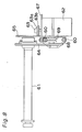
As shown in Figs. 1 and 7 through 9, the film
winding mechanism 15 can freely move into a film
dismounting position in which the mechanism 15 protrudes
outwardly of an end portion 8a (forward end 8a in the
moving direction of the movable platen 3) of the
apparatus main body 8 and a film winding position inside
the apparatus main body 8.
With this arrangement, the film winding
mechanism 15 can be positioned inside the apparatus main
body 8 during the molding operation, so that the
mechanism 15 does not obstruct a person walking along the
periphery of the apparatus main body 8, or in a similar
case.
Moreover, when dismounting the used transfer
film 20, which is wound after the transfer operation, the
dismounting work can be carried out by moving the film
winding mechanism 15 outwardly of the apparatus main body
8, facilitating the film dismounting work.
In this embodiment, the film winding mechanism
15 includes an upper and a lower guide rails 60 attached
in parallel to the apparatus main body 8 (base plate 6)
so as to extend in the film movement direction, and end
portions of these guide rails 60 protrude outwardly of
the end portion 8a of the apparatus main body 8. The
guide rails 60 are connected to the apparatus main body 8
(base plate 6) with a connector 66.
The guide rails 60 have a hexagonal sectional
shape as shown in Fig. 8, and are connected via a plate
68. The guide rails 60 are adjustable in length and able
to take a protruded posture in which the rails are
protruded from the end portion 8a of the apparatus main
body 8.
In this embodiment, as shown in Figs. 7 and 9,
the guide rails include base portion guide rails 60a and
tip portion guide rails 60b connected to the apparatus
main body 8 (base plate 6) with a connector 66, and the
base portion guide rails 60a and tip portion guide rails
60b are bendably connected via a hinge 60c. The hinge
60c includes a first piece 81 and a second piece 82
pivotally joined to each other via a pin 83, and the tip
portion of the guide rail 60b is attached to the first
piece 81, while the base portion of the guide rail 60a is
attached to the second piece 82.
Specifically, as shown in Fig. 9, the one side
piece 81 has a pair of pin bearing portions 81a, and the
other side piece 82 has a configuration that includes a
movable plate 82c having a pin bearing portion 82b at its
fitting portion 82a. The pin bearing portions 81a and
82b are joined together via the pin 83.
When the base portion guide rails 60a and the
tip portion guide rails 60b are rectilinearly extended,
the tip portion guide rails 60b project beyond the edge
8a of the apparatus main body 8, thus to present the
protruded posture. When the tip portion guide rails 60b
are folded, the tip portion guide rail 60b are
accommodated in the apparatus main body 8, thus to enter
the retracted posture. Here, to enter the retracted
posture, the tip portion guide rails 60b may be folded to
a direction opposite (i.e. upward in Fig. 7) to the arrow
in Fig. 7. Such configuration allows reducing the
portion protruding from the apparatus main body 8, by
folding the tip portion guide rails 60b to the same
direction as the winding reel 61, to be subsequently
described.
Providing the hinge thus constructed between
the tip portion guide rails 60b and the base portion
guide rails 60a allows presenting the retracted posture
by folding the tip portion guide rails 60b at the hinge
60c.
Also, in the example shown in Fig. 9, the hinge
60c is fixed to the guide rail such that the pin bearing
portions 81a, 82b are located on the side where a movable
member 64 is not provided, so as to allow the guide rail
to be folded in the direction indicated by the arrow in
Fig. 7, and to thereby avoid the interference between the
tip portion guide rail 60b and the movable member 64.
Further, the guide rail 60 may have a
telescopic structure, to present both the retracted
posture in which the guide rail is accommodated inside
the apparatus main body 8 and the protruded posture in
which the guide rail is projecting beyond the edge 8a of
the apparatus main body 8.
Also, the base portion guide rail 60a is
provided with a bracket 67 attached to the end portion
opposite to the hinge 60c, and a third motor 62 is
mounted on the bracket 67. The third motor 62 includes a
rotating member 63 rotationally driven by the third motor
62.
The guide rail 60 is provided with the movable
member 64 that can move between the film releasing
position and film winding position. The movable member
64 is provided with a wheel 69 contacting the lower face
of the upper rail 601 and wheels 69 contacting the upper
face of the lower rail 602, so as to be held between the
guide rails 60 and thus to smoothly move along the guide
rails 60.
The wheels 69 attached to the movable member 64
have a dovetail groove, which fits the guide rail having
a hexagonal sectional shape, and prevents the wheel 69
from falling off from the guide rail and shifting in the
widthwise direction of the guide rail.
The winding reel 61 is rotatably supported by
the movable member 64 that moves along the guide rails 60,
and a rotary disk 65 is attached to a tip portion of the
winding reel 61, perpendicularly to the rotation axis of
the winding reel 61.
When the movable member 64 is at the film
winding position indicated by the imaginary line in Fig.
7, the winding reel 61 is driven to rotate by the third
motor 62, at the film winding position as shown in Fig. 8.
More specifically, when the movable member is
located at the film winding position, the rotary disk 65
and the rotating member 63 of the third motor are brought
into contact, or preferably into pressure contact with
each other. When the third motor 62 is activated to
drive the rotary disk 65 to rotate, the rotational force
is transmitted to the rotary disk 65 because of the
friction acting therebetween, thus causing the winding
reel 61 to rotate. In this embodiment, the rotating
member 63 is provided with a rubber ring 63b attached to
the outer circumferential surface of the rotary disk 63a,
thus to increase the frictional resistance.
A specific configuration of each sensor will be
described.
The lengthwise direction sensor 30 and the
first and second widthwise direction sensors 31 and 32
are movable in the direction of movement of the movable
platen 3 (thickness direction of the transfer film 20),
the direction of movement of the transfer film 20
(lengthwise direction) and the widthwise direction of the
transfer film 20, and are able to adjust the position in
the lengthwise direction according to the size of the
pattern 21 of the transfer film 20 and the size of the
dies, able to adjust the position in the direction of
movement of the movable platen 3 according to the size of
the dies (size in the direction of movement of the
movable platen 3), and able to adjust the position in the
widthwise direction according to the width of the
transfer film 20.
For example, as shown in Figs. 1 and 2, a first
movable member 71 is mounted movably in the direction of
movement of the movable platen 3 along lateral guides 70
mounted on each of the brackets 40 and 56, and vertical
rods 72 are supported to each first movable member 71
slidably in the direction of movement of the transfer
film 20 (vertical direction). A second movable member 73
is mounted on each vertical rod 72, and each second
movable member 73 is made movable in the vertical
direction.
A bracket 74 is mounted on this second movable
member 73 movably in the widthwise direction of the
transfer film 20.
By mounting the light emitters 33 and the light
detectors 34 on the brackets 74, the lengthwise direction
sensor 30 and the first and second widthwise direction
sensors 31 and 32 are provided.
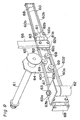
Specifically, as shown in Fig. 10, the first
movable member 71 is fixed by tightening first screws 75,
and the first movable member 71 is moved along the
lateral guides 70 by loosening the screws 75.
The vertical rods 72 are fixed by tightening
second screws 76, and the vertical rods 72 are vertically
moved with respect to the first movable member 71 by
loosening the screws 76.
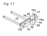
As shown in Fig. 11, the bracket 74 is provided
with a mounting piece 74a and a sensor mounting piece 74b,
and the sensor mounting piece 74a is fixed by bolts 77
supported movably along a dovetail groove 73a of the
second movable member 73. When the bolts 77 are loosened,
the bracket 74 moves along the dovetail groove 73a in the
widthwise direction of the transfer film 20 with respect
to the second movable member 73.
The light emitter 33 and the light detector 34
are mounted on the sensor mounting piece 74b of each of
the bracket 74, and a pair of guides 78 that facilitate
the insertion of the transfer film 20 between the light
emitter 33 and the light detector 34 are provided.
Regarding the attachment structure of the
sensors shown in Figs. 10 and 11, since the attaching
positions of the lengthwise direction sensor 30 and the
first and the second widthwise direction sensor 31, 32
are different from one another, two structures that are
horizontally symmetric are provided, out of which the one
shown in Fig. 11 is for attaching the first widthwise
direction sensor 31, while the other for attaching the
lengthwise direction sensor 30 and the second widthwise
direction sensor 32 has a structure horizontally
symmetrical with that of Fig. 11.
Hereunder, the control of the transferring and
molding apparatus constituted as above will be described.
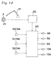
The transferring and molding apparatus shown in Fig. 1 is
driven under the control of a control mechanism. As
shown in Fig. 12, the driving mechanism includes a
controller 90, which receives an output signal including
information on the amount of received light from the
respective light detectors 34 of the lengthwise direction
sensor 30 and the first and the second widthwise
direction sensors 31 and 32.
The controller 90 calculates the amounts of
shift between the marks 22, 23 and the respective sensors
30, 31, 32 on the basis of the inputted quantities of
received light, detects the transfer position (shift
dimension at the time of transfer) of the transfer film
20 as digital values and stores the values.
The molded article "b", onto which the pattern
21 has been transferred, is conveyed to the outside of
the molding section of the dies by a robot arm 91.
Subsequently, the shift dimensions L1 and H1 and the shift
direction of the pattern 21 of the molded article are
detected as digital values in an image recognition unit
92, and the detected shift dimensions L1 and H1 and the
shift direction are inputted to the controller 90. This
operation is carried out at any time. The operation is
carried out, for example, every 500 times molding.
The controller 90 determines the necessity of
positional correction of the transfer film 20 on the
basis of the inputted shift dimensions.
When the controller 90 determines that the
positional correction is required to be carried out by
moving the transfer film 20 in the lengthwise direction,
then the positional correction is carried out by moving
the transfer film 20 in the direction opposite from the
shift direction in the lengthwise direction by
controlling the driving of the first, second and third
motors 46, 52 and 62 on the basis of the lengthwise
direction shift dimension L1 and the shift direction.
The lengthwise direction sensor 30 monitors the
lengthwise position of the transfer film 20 based on
variation of the amount of light received by the
lengthwise direction sensor 30, simultaneously with the
movement of the transfer film 20, and once the controller
90 detects that the transfer film 20 has come to the
position where the lengthwise direction shift dimension
L1 can be corrected, then the first, second and third
motors 46, 52 and 62 are stopped so as to stop the
transfer film.
By this operation, the positional correction in
the lengthwise direction of the transfer film 20 is
completed.
If the controller 90 determines that the
positional correction is required to be carried out by
moving the transfer film 20 in the widthwise direction,
then the transfer film 20 is moved in the direction
opposite from the shift direction in the widthwise
direction by controlling the driving of the motors 12b
and 13b of the first and second movement mechanisms 12
and 13 on the basis of the widthwise direction shift
dimension H1 and the shift direction.
Simultaneously with this operation, the first
and second widthwise direction sensors 31 and 32 monitor
the widthwise position of the transfer film similarly to
the aforementioned case, based on a variation of the
quantity of light received, and once the controller 90
detects that the transfer film 20 has come to the
position where the widthwise direction shift dimension H1
can be corrected, the motors 12b and 13b are stopped.
By this operation, the positional correction in
the widthwise direction of the transfer film 20 is
completed.
If the positional correction of the transfer
film 20 ends as described above, then the transferring
and molding operation is carried out several times. The
operation is carried out, for example, six times.
Subsequently, the molded article is conveyed to the image
recognition unit 92 similarly to the aforementioned
operation, and the shift dimension and direction of the
pattern 21 of the molded article are detected again and
inputted into the controller 90.
If the controller 90 determines that positional
correction is required to be carried out, the
aforementioned positional correction operation is carried
out again.
In this case, there is detected a difference
between the shift dimension of the pattern 21 of the
molded article "b" that has undergone the transferring
and molding before the positional correction of the
transfer film 20 and the shift dimension of the pattern
21 of the molded article "b" that has undergone the
transferring and molding after the positional correction
of the transfer film 20.
Then, the transfer film 20 is moved by this
difference. For example, if the quantity of movement of
the transfer film 20 detected as described above
coincides with the aforementioned difference, then the
motors 44, 52, 65, 12b, 13b is stopped.
If the controller 90 determines that there is
no need to carry out the positional correction by
repeating this operation, then the normal transferring
and molding operation is carried out.
The determination of the positional correction
in this description is made depending on whether or not
the aforementioned shift dimension of the pattern 21 of
the molded article is within the tolerance range.
In the case where there is a difference between
the widthwise direction shift dimension H2 on the forward
side in the lengthwise direction and the widthwise
direction shift dimension H3 on the rearward side in the
lengthwise direction as shown in Fig. 6C, the pattern 21
is transferred aslant onto the molded article "b".
Therefore, the motor 12b of the first movement mechanism
12 and the motor 13b of the second movement mechanism 13
are independently driven, and the positional correction
is carried out by moving the forward side and the
rearward side in the lengthwise direction of the transfer
film 20 in the opposite direction in the widthwise
direction.
In the above description, the operation of
moving the transfer film 20 for the positional correction
may be carried out after moving the transfer film 20 to
the transfer position as usual or before moving the
transfer film 20 to the transfer position.
Further, in this embodiment, since a tension of
the transfer film 20 is adjusted by controlling the
braking force of the feed reel 44 and the driving force
of the driving roller 50, servo motors are employed as
the first and the second motors 46, 52. For the winding
reel 61, an induction motor is employed since the winding
reel 61 only serves to collect the used transfer film 20.
Also, when the film winding diameter on the winding reel
becomes larger, it does not affect the tension of the
transfer film 20 between the feed reel 44 (film feeding
unit 10) and the driving roller 50 (film tension
mechanism 14).
It is to be understood that the present
invention is not limited to the foregoing embodiments,
but various modifications may be made.
To cite a few examples, while the protruding
direction of the marks is detected by the sensors 30, 31,
32, and historic records of the shielding ratio are kept
during the movement of the transfer film for detecting
the position and the shift direction of the transfer film
in the foregoing embodiments, alternatively two light
emitters and light detectors may be provided to one
sensor at different positions, so that the shift
direction can be detected by comparison of the shielding
ratio of the two light detectors.
Also, the detection of the pattern shift on the
molded article by the pattern detection section may be
performed at a desired frequency, and such detection
frequency may be appropriately changed according to the
molding condition. For example, after executing the
positional correction of the transfer film, the pattern
shift detection may be performed at a higher frequency,
and then less frequently with the lapse of time.
Further, the information obtained through
detection of the pattern shift on the molded article by
the pattern detection section may be stored, and an
average value of the accumulated information values may
be calculated when a predetermined condition is satisfied,
for example when a predetermined amount of information
has been accumulated or when a predetermined time has
elapsed, so as to execute the positional correction of
the transfer film based on the average value obtained.
Executing thus the positional correction based on the
average value allows correcting the pattern shift at high
accuracy over an entirety of the successive transferring
and molding process. In other words, since the transfer
position of the pattern is only slightly different among
the molded articles produced through the successive
transferring and molding process, it is effective to
store the first digital value and to perform the
positional correction of the transfer film based on an
average value thereof, thus to correct the position shift
of the pattern with high accuracy over an entirety of the
successive transferring and molding process.
In addition, regarding the film winding unit 11,
the film winding mechanism 15 may be disposed so as to be
moved in the widthwise direction of the transfer film by
the second movement mechanism.
By properly combining any selected embodiments
out of the aforementioned various embodiments, the
advantageous effects appropriate to the respective
embodiments can be equally attained.
Although the present invention has been fully
described in connection with the preferred embodiments
thereof with reference to the accompanying drawings, it is
to be noted that various changes and modifications are
apparent to those skilled in the art. Such changes and
modifications are to be understood as included within the
scope of the present invention as defined by the appended
claims unless they depart therefrom.