EP1599868B1 - Verfahren und Vorrichtung zur Rekonstruktion des Spektrums eines Audiosignals - Google Patents
Verfahren und Vorrichtung zur Rekonstruktion des Spektrums eines Audiosignals Download PDFInfo
- Publication number
- EP1599868B1 EP1599868B1 EP04716626A EP04716626A EP1599868B1 EP 1599868 B1 EP1599868 B1 EP 1599868B1 EP 04716626 A EP04716626 A EP 04716626A EP 04716626 A EP04716626 A EP 04716626A EP 1599868 B1 EP1599868 B1 EP 1599868B1
- Authority
- EP
- European Patent Office
- Prior art keywords
- frequency
- coder
- coded
- decoder
- core
- Prior art date
- Legal status (The legal status is an assumption and is not a legal conclusion. Google has not performed a legal analysis and makes no representation as to the accuracy of the status listed.)
- Expired - Lifetime
Links
- 230000005236 sound signal Effects 0.000 title claims abstract description 71
- 238000000034 method Methods 0.000 title claims abstract description 27
- 230000003595 spectral effect Effects 0.000 title claims abstract description 27
- 238000001228 spectrum Methods 0.000 claims abstract description 87
- 238000004590 computer program Methods 0.000 claims abstract description 5
- 230000000295 complement effect Effects 0.000 claims abstract description 4
- 230000005540 biological transmission Effects 0.000 claims description 22
- 238000012546 transfer Methods 0.000 description 10
- 238000010586 diagram Methods 0.000 description 6
- 101000969688 Homo sapiens Macrophage-expressed gene 1 protein Proteins 0.000 description 5
- 102100021285 Macrophage-expressed gene 1 protein Human genes 0.000 description 5
- 230000008929 regeneration Effects 0.000 description 5
- 238000011069 regeneration method Methods 0.000 description 5
- 238000012937 correction Methods 0.000 description 4
- 238000012545 processing Methods 0.000 description 4
- 230000010076 replication Effects 0.000 description 4
- 230000006978 adaptation Effects 0.000 description 3
- 238000004891 communication Methods 0.000 description 2
- 230000003111 delayed effect Effects 0.000 description 2
- 239000000284 extract Substances 0.000 description 2
- 230000006870 function Effects 0.000 description 2
- 230000008447 perception Effects 0.000 description 2
- 230000009466 transformation Effects 0.000 description 2
- 230000007547 defect Effects 0.000 description 1
- 238000003780 insertion Methods 0.000 description 1
- 230000037431 insertion Effects 0.000 description 1
- 238000003672 processing method Methods 0.000 description 1
- 230000000750 progressive effect Effects 0.000 description 1
- 238000013139 quantization Methods 0.000 description 1
- 238000007493 shaping process Methods 0.000 description 1
- 230000017105 transposition Effects 0.000 description 1
- 230000002087 whitening effect Effects 0.000 description 1
Images




Classifications
-
- G—PHYSICS
- G10—MUSICAL INSTRUMENTS; ACOUSTICS
- G10L—SPEECH ANALYSIS TECHNIQUES OR SPEECH SYNTHESIS; SPEECH RECOGNITION; SPEECH OR VOICE PROCESSING TECHNIQUES; SPEECH OR AUDIO CODING OR DECODING
- G10L19/00—Speech or audio signals analysis-synthesis techniques for redundancy reduction, e.g. in vocoders; Coding or decoding of speech or audio signals, using source filter models or psychoacoustic analysis
- G10L19/02—Speech or audio signals analysis-synthesis techniques for redundancy reduction, e.g. in vocoders; Coding or decoding of speech or audio signals, using source filter models or psychoacoustic analysis using spectral analysis, e.g. transform vocoders or subband vocoders
-
- G—PHYSICS
- G10—MUSICAL INSTRUMENTS; ACOUSTICS
- G10L—SPEECH ANALYSIS TECHNIQUES OR SPEECH SYNTHESIS; SPEECH RECOGNITION; SPEECH OR VOICE PROCESSING TECHNIQUES; SPEECH OR AUDIO CODING OR DECODING
- G10L19/00—Speech or audio signals analysis-synthesis techniques for redundancy reduction, e.g. in vocoders; Coding or decoding of speech or audio signals, using source filter models or psychoacoustic analysis
- G10L19/005—Correction of errors induced by the transmission channel, if related to the coding algorithm
-
- G—PHYSICS
- G10—MUSICAL INSTRUMENTS; ACOUSTICS
- G10L—SPEECH ANALYSIS TECHNIQUES OR SPEECH SYNTHESIS; SPEECH RECOGNITION; SPEECH OR VOICE PROCESSING TECHNIQUES; SPEECH OR AUDIO CODING OR DECODING
- G10L19/00—Speech or audio signals analysis-synthesis techniques for redundancy reduction, e.g. in vocoders; Coding or decoding of speech or audio signals, using source filter models or psychoacoustic analysis
- G10L19/02—Speech or audio signals analysis-synthesis techniques for redundancy reduction, e.g. in vocoders; Coding or decoding of speech or audio signals, using source filter models or psychoacoustic analysis using spectral analysis, e.g. transform vocoders or subband vocoders
- G10L19/0204—Speech or audio signals analysis-synthesis techniques for redundancy reduction, e.g. in vocoders; Coding or decoding of speech or audio signals, using source filter models or psychoacoustic analysis using spectral analysis, e.g. transform vocoders or subband vocoders using subband decomposition
- G10L19/0208—Subband vocoders
-
- G—PHYSICS
- G10—MUSICAL INSTRUMENTS; ACOUSTICS
- G10L—SPEECH ANALYSIS TECHNIQUES OR SPEECH SYNTHESIS; SPEECH RECOGNITION; SPEECH OR VOICE PROCESSING TECHNIQUES; SPEECH OR AUDIO CODING OR DECODING
- G10L19/00—Speech or audio signals analysis-synthesis techniques for redundancy reduction, e.g. in vocoders; Coding or decoding of speech or audio signals, using source filter models or psychoacoustic analysis
- G10L19/04—Speech or audio signals analysis-synthesis techniques for redundancy reduction, e.g. in vocoders; Coding or decoding of speech or audio signals, using source filter models or psychoacoustic analysis using predictive techniques
- G10L19/16—Vocoder architecture
- G10L19/18—Vocoders using multiple modes
- G10L19/24—Variable rate codecs, e.g. for generating different qualities using a scalable representation such as hierarchical encoding or layered encoding
Definitions
- the present invention relates to a method and a device for encoding and decoding an audio signal employing spectrum reconstruction techniques.
- the invention lies in the improvement of the decoding of an audio signal encoded by a spectral band limiting coder, called a core coder.
- This coding may be a rate reduction coding.
- Known rate reduction encoders are, for example, transform type encoders such as MPEG1, MPEG2 or MPEG4-GA encoders, CELP type encoders and even parametric type encoders, such as a parametric MPEG4 type encoder.
- the audio signal In audio reduction rate coding, the audio signal must often be bandwidth-restricted when the bit rate becomes low. This bandwidth limitation is necessary to avoid the introduction of audible quantization noise into the coded signal. It is therefore desirable to complete as far as possible the complete spectral content of the original signal.
- Band widening is known from the state of the art, such as the spectral broadening method known as the High Frequency Regeneration (HFR) method.
- the decoded, low-bandwidth low-frequency signal is subjected to a non-linear device to obtain a signal enriched in harmonics.
- This signal after whitening and shaping based on information describing the spectral envelope of the full-band signal before coding, allows the generation of a high frequency signal corresponding to the high frequency content of the signal before coding.
- These systems perform a time adaptation of the cutoff frequency between the low frequency band coded by an encoder, called the core coder, and the high frequency band coded by an HFR system, called a band extension coder.
- the core encoder and the band extension encoder distribute the bandwidth according to the appropriate cutoff frequency.
- This type of system is particularly interesting for coding audio signals.
- Certain communication networks such as the Internet, wireless communication networks and others do not guarantee a perfect routing of data between the sender and the recipient. Some data may never reach the recipient or arrive too late. Arriving too late, the recipient considers them lost.
- the invention attempts to overcome the disadvantages of the prior art by proposing a coding method according to claim 1 and the corresponding device according to claim 9.
- the decoded signal will be of better quality, no spectral component of the signal is missing, the frequency spectrum decoded with the extension decoder being modified according to the cutoff frequency of the signal decoded by the core encoder.
- the portion of the frequency spectrum of the decoded audio signal with a heart decoder is the lower part of the frequency spectrum of the audio signal.
- the information representative of at least one cut-off frequency of the signal decoded by the heart decoder is obtained by making an estimate of the high cut-off frequency of the signal decoded by the heart decoder.
- the information representative of at least one cut-off frequency of the signal decoded by the heart decoder is obtained from information included in the data stream comprising the coded digital signal.
- the heart decoder is a hierarchical decoder and information is obtained representative of the bandwidth of the signal decoded by the heart decoder for each layer of the decoded signal.
- the decoder can adapt the processing to each coding layer, the decoder has this information at each layer and can thus modify the frequency spectrum decoded with the extension decoder according to this information.
- the invention according to claims 17 and 18 also relates to the computer program stored on an information carrier, said program comprising instructions for implementing the previously described processing method, when it is loaded and executed by a user. computer system.
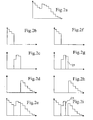
- the Fig. 1a represents a frequency spectrum of an audio signal to be encoded.
- the low frequencies of the spectrum ( Fig. 1b ) are encoded by a core encoder, while the high frequencies are encoded by an extension encoder. This part of the high frequencies is represented in Fig. 1 C .
- the Fig. first represents the frequency spectrum of a decoded audio signal with a heart decoder, the encoded audio signal having been transmitted over a network and some data has been lost.
- the information encoded by the extension encoder is much more limited in number.
- the frequency spectrum of an audio signal transmitted over a network and decoded with an extension decoder is considered correct. This is represented at Fig. 1f .
- the Fig. 2a represents the frequency spectrum of the total audio signal to be encoded by a hierarchical core encoder and an extension encoder.
- a hierarchical core encoder will successively encode different subparts of the frequency spectrum of the audio signal to be encoded.
- a first part of the spectrum for example the part containing the lowest frequency components, such as the spectrum represented in Fig. 2b , will be coded.
- the first layer This is called the first layer. Then another part containing additional frequency components will be coded. This is the second layer, she is represented at the Fig. 2c .
- the information representative of the lowest frequencies is generally transmitted in the first layers.
- the other layers are, for example, then transmitted in an order according to the frequencies of the spectrum that they represent.
- some of the layers of the transmitted layers have a higher priority character than others.
- the layers with the lowest frequencies are considered as priority
- the layers with the highest frequencies are considered as the lowest priorities.
- the layers with the lowest frequencies are associated with efficient error correction codes, ensuring good decoding, so no transmission losses.
- the Fig. 2d represents the part of the spectrum allocated to the band extension encoder, it is identical to that described in Fig. first .
- Figs. 2f and 2g represent the frequency spectra of a decoded audio signal with a hierarchical heart decoder comprising two hierarchy layers, the coded audio signal having been transmitted over a network and some layers of which have been lost.
- the part of the spectrum allocated to the band extension encoder is identical to that described in Fig. 1 C . She is represented at Fig 2h .
- the Fig. 3a represents the frequency spectrum of the total audio signal to be encoded by a core encoder and an extension encoder according to the invention.
- the core encoder encodes the low frequency components of the frequency spectrum of the audio signal, this is shown in FIG. Fig. 3b .
- the extension coder not only encodes the high frequency components of the frequency spectrum of the audio signal to be coded but also a portion of the low frequency components that the core code coder . These components are represented at Fig. 3c .
- the Fig. 3d represents the frequency spectrum of an audio signal decoded with a heart decoder, the coded audio signal having been transmitted over a network and some layers 31 have been lost.
- An estimate of the bandwidth of the audio signal decoded by the heart decoder is performed, if it is different from that expected, the heart decoder informs the extension decoder of the missing bandwidth.
- the extension decoder adapts the decoding so that the decoding also applies to the missing bandwidth.
- Fig 3rd is represented the frequency spectrum equivalent to the coded information received by the extension decoder. This spectrum is composed of components 32,33 and 34.
- the information corresponding to the component 34 is sufficient for the decoding.
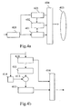
- the Fig. 4a represents a block diagram describing the coding device according to the invention.
- the coding device consists of a digital analog converter 400 which converts the analog signal to be encoded into a digital signal.
- a digital analog converter 400 which converts the analog signal to be encoded into a digital signal.
- the analog-to-digital converter is not necessary.
- the digital signal is delivered to the heart encoder which encodes this signal.
- the core encoder is for example a rate reduction encoder as conforming to one of the MPEG1, MPEG2 or MPEG4-GA standards, or a CELP type encoder, a hierarchical coder, or even a parametric MPEG4 encoder.
- the output of the core encoder represents the data of the signal covering the frequency spectrum such as that represented in FIG. Fig. 3b .
- the band extension encoder is for example an HFR (High Frequency Regeneration) type encoder, for example SBR (Spectral Band Replication) as described in FIG. document "Audio Engineering Society, convention paper 5553", presented at the 112th AES Convention by Mr Martin Dietz .
- HFR High Frequency Regeneration
- SBR Spectrum Band Replication
- the output of the band extension encoder represents the signal envelope data covering the frequency spectrum such as that shown in FIG. Fig. 3c .
- a cutoff frequency adjustment module 402 is connected to the tape extension encoder 403 and the core encoder 401.
- This module 402 defines the frequency spectrum that the extension encoder takes into account for coding.
- This module 402 determines this spectrum as a function of the high cut-off frequency of the core encoder 401, and of a variable frequency band which enables the decoder according to the invention to be able to overcome the possible transmission losses.
- variable frequency band is adjusted so as to guarantee the correct Recomposing the signal for layers that do not have a robust error correction code.
- the frequency spectrum of the core encoder 401 can be adjusted from the frequency spectrum of the extension encoder 403.
- the module 402 defines the frequency spectrum that the core encoder 401 takes into account for the coding.
- This module 402 defines this spectrum as a function of the low cut-off frequency of the extension encoder 403 and of a variable frequency band which enables the decoder according to the invention to be able to overcome the possible transmission losses.
- the coding device also comprises a multiplexer 404 which multiplexes the audio signals coded by the core coder 401 and by the extension coder 403.
- the module 402 transfers to the multiplexer 404 the information representative of the passband of the core encoder 401 or its cutoff frequencies, or even the low cutoff frequency of the extension encoder 403 so that these included in the transmitted data.
- the inclusion is performed in the case of a hierarchical coder for each coding layer.
- the multiplexed data is then transferred to a network transmission module which, for example in the case of a radio transmission, applies error correcting codes to the multiplexed data and transmits them to the network 405.
- the Fig. 4b represents a block diagram describing the main elements of a hierarchical heart encoder.
- This hierarchical coder can replace the encoder 401 previously described with reference to the Fig. 4a .
- a hierarchical heart encoder usually subdivides the frequency spectrum to be coded into different layers.
- a layer represents a frequency band of the spectrum to be coded.
- the number of layers is variable and allows a progressive transmission of the coded signal.
- the encoder consists of a first encoder 410 which encodes the lowest part of the frequency spectrum of the original signal.
- the encoded information is transferred to a multiplexer 416 which transfers this data to the multiplexer 404.
- module 402 transfers to the multiplexer 404 the information representative of the bandwidth of the core encoder 410 so that they are included in the data stream associated with this layer.
- the coded information is also transferred to a decoder 411. This decoder decodes this information and then transmits it to a subtraction circuit 413 which will subtract the decoded signal from the original signal.
- the original signal has previously been delayed by a delay equal to the coding time of the encoder 410 and the decoding time of the decoder 411.
- the signal obtained at the output of the subtracter circuit is then the original signal in which the previously coded low frequency components have been removed to the coding residue.
- This signal is again coded by an encoder 415 which may be of the same type as the encoder 410.
- the frequency components of the signal greater than those coded by the encoder 410 are coded.
- the encoded information is transferred to a multiplexer 416 which transfers this data to the multiplexer 404.
- the module 402 transfers to the multiplexer 404 the information representative of the bandwidth of the core encoder 415 so that they are included in the data stream associated with this layer. It can also transfer the total number of coding layers, the high or low cutoff frequency of the core encoder 415.
- the elements 410, 411, 413 and 414 will have to be duplicated for each additional layer.
- each encoder may be variable: It should also be noted that the invention is applicable for mono, stereo or multi-channel audio signals.
- the bandwidth information transmitted by the coder can be transmitted in a conjugated manner or in a preferential mode, the bandwidth of each of the channels can be deduced from the other channels by a differential coding.
- the Fig. 5 represents a block diagram describing the decoding device according to the invention.
- the decoding device consists of a demultiplexer 510 which separates the signals received via the network 405 into data intended for the heart decoder 511 and data intended for the extension decoder 512. It also extracts signals received, the information representative of the bandwidth of the core encoder 401 of the coding device, the encoders 410 and 415 if the signal has been encoded with a hierarchical coder, or even the low cutoff frequency of the encoder extension 403 of the coding device if these were included in the transmitted data.
- the heart decoder 511 decodes the data to provide a decoded signal such as the signal shown in FIG. Fig. 3d .
- the core decoder 511 is, for example, a decoder such as one of the MPEG1, MPEG2 or MPEG4-GA standards, or a CELP type decoder, a hierarchical decoder, or even a parametric MPEG4 decoder.
- the heart decoder 511 comprises a module 511b for obtaining information representative of at least one cutoff frequency which estimates, according to a first embodiment, the frequency spectrum of the signal received by the latter.
- the module 511b does this for example by performing a time-frequency transformation on the decoded signal and determining the frequency from which the signal energy becomes negligible. Preferably, this can be done with the assistance of a perception model.
- the decoder 511 more precisely its 511b module then transfers information representative of the cutoff frequency or the bandwidth to the extension decoder 512.
- the extension decoder 512 selects, from the representative information transmitted by the decoder 511, among the coded data received from the multiplexer 510, the data corresponding to a representation of the spectral envelope greater than the determined frequency. by the encoder 511.
- the core decoder 511 more precisely the module 511b for obtaining information representative of at least one cut-off frequency obtains from the demultiplexer 510, according to a second embodiment, the information representative of the bandwidth of the core encoder 401 or encoders 410 and 415 of the coding device, or even the number of layers of the coded signal, or even the low cutoff frequency of the encoder 403 extension encoder if they were included in the data transmitted.
- the module 511 b checks, in the case where it is a hierarchical decoder, if each layer is well received and in the negative transfers information representative of the bandwidth of one or more lost layers to the extension decoder 512.
- the extension decoder 512 selects, from the representative information transmitted by the module 511b, among the coded data received from the multiplexer 510, the data corresponding to the envelope of the signal corresponding to a representation of the spectral envelope of the frequencies. higher than the lowest frequency corresponding to the lost frequency bands.
- the extension decoder corrects the losses due to the network either on losses affecting the last layers received or losses affecting an intermediate layer.
- the band extension decoder 512 is for example a HFR (High Frequency Regeneration) type decoder, for example a SBR (Spectral Band Replication) type decoder as described in the document "Audio Engineering Society, convention paper 5553", presented at the 112th AES Convention by Mr Martin Dietz .
- HFR High Frequency Regeneration
- SBR Spectrum Band Replication
- the extension decoder 512 decodes all the information received. A selection among the decoded data is performed so as to keep only those corresponding to a representation of the spectral envelope greater than the frequency determined by the encoder 511.
- the envelope decoded by the extension decoder 512 or selected is transferred to a gain control module 515.
- the signal decoded by the heart decoder 511 is sent to a transposition module 513 which generates a signal in the high frequencies of the spectrum from the low frequency decoded signal.
- This signal is fed into the gain control module 515 to allow adjustment of the high frequency signal envelope.
- the adjusted envelope signal is then added to the decoded signal by the heart decoder 511 with an adder 516.
- the adder 516 may in a preferred mode favor certain frequency components by multiplying for example certain components by coefficients.
- the signal decoded by the heart decoder 511 has been previously delayed by a delay equal to the difference in processing time between the summed signals. This delay is performed by the delay circuit 514.
- the frequency spectrum of the signal obtained is thus similar to that of the Fig. 3f .
- the summation signal can then be converted to analog form using a digital to analog converter 517.
- the Fig. 6 represents the algorithm performed according to the invention at the coder.
- the invention as described with reference to FIGS. preceding is also feasible in software form in which a processor executes the executable code associated with the steps E1 to E7 of the algorithm of the Fig. 6 .
- the processor When the coding device is powered up, and more particularly in the case of using a computer as coding device, the processor reads from the read-only memory of the computer or an information medium such as a compact disc CD-ROM, the instructions of the program corresponding to steps E1 to E7 of the Fig. 6 and loads RAM RAM to run them.
- step E1 on receiving audio data to be coded, the processor determines the bandwidth of the core encoder or at least one cutoff frequency.
- the bandwidth of the core coder may or may not be variable in time depending for example on the load of the core coder.
- the processor encodes the data according to an algorithm called core coding according to one of the MPEG1, MPEG2 or MPEG4-GA standards, or of the CELP type, of the hierarchical type, or even of the parametric MPEG4 type.
- Step E2 consists in verifying whether, and in the case of a hierarchical coding, all the layers have been coded or not.
- the processor repeats the step E1 for each layer of the coded audio signal.
- step E3 the processor determines a frequency margin.
- This margin can be predetermined and stored in a register or be in the form of a variable.
- This variable depends, for example, on the type of error correction that will be applied to the coded data during transmission on the network.
- the processor determines in step E4, from the margin and the high cutoff frequency of the core encoder, the low cutoff frequency of the extension encoder.
- the processor transfers this information to the extension coding routine at step E5.
- step E6 the processor stores this information.
- the processor executes the extension coding by coding the data whose spectrum is greater than the information transferred to the step E5.
- the band extension coding is for example a High Frequency Regeneration (HFR) type coding, for example SBR (Spectral Band Replication) as described in the document. "Audio Engineering Society, convention paper 5553", presented at the 112th AES Convention by Mr Martin Dietz .
- HFR High Frequency Regeneration
- step E7 which consists of multiplexing the audio signals encoded in step E1 and the audio signals encoded in step E7 to form a stream of coded data transmitted over a network.
- the processor inserts in the coded and transmitted data stream, the information stored in step E6 or inserts one or more of the following information: heart coder bandwidth, coder bandwidth extension, low and high frequency of each coding layer, number of coding layers if a hierarchical coder is used.
- Insertion is performed in the case of a hierarchical coder for each coding layer.
- the processor returns to step E1 waiting for new audio data to be coded.
- the Fig. 7 represents the algorithm performed according to the invention at the level of the decoder.
- the processor When the reception device is powered up, and more particularly in the case of using a computer as a receiving device, the processor reads from the read-only memory of the computer or of an information medium such as a compact disc CD-ROM, the instructions of the program corresponding to steps E10 to E15 of the Fig. 7 and loads RAM RAM to run them.
- the processor on receiving audio data to be decoded, separates the signals received via the network 405 into data intended for the heart decoder and data intended for the extension decoder. It also extracts signals received, information representative of the bandwidth or at least one cut-off frequency of the core encoder encoding the audio signal, or encoders encoding the audio signal if the signal has been coded with an encoder hierarchy, or even the low cut-off frequency of the extension encoder encoding the audio signal if they have been included in the transmitted data.
- step E7 The processor then proceeds to decode this data.
- the processor proceeds to decode the data according to a decoding algorithm called core decoding as conforming to one of the MPEG1, MPEG2 or MPEG4-GA standards, or of the CELP type, a hierarchical decoding, or even a parametric MPEG4 type decoding. .
- core decoding as conforming to one of the MPEG1, MPEG2 or MPEG4-GA standards, or of the CELP type, a hierarchical decoding, or even a parametric MPEG4 type decoding.
- step E12 is a step of obtaining information representative of at least one cutoff frequency which estimates, according to a first embodiment, the frequency spectrum of the signal received by this one. This is done for example by performing a time-frequency transformation on the decoded signal in step E11 and determining the frequency from which the signal energy becomes negligible. Preferably, this can be done with the assistance of a perception model.
- the processor obtains the information extracted in step E1 and verifies, in the case where the latter is a hierarchical decoder, whether each layer is well received and, if not, transfers information representative of the bandwidth. from one or more layers lost to the extension decoder.
- step E13 consists of an adaptation of the low cutoff frequency of the expansion decoder so that it compensates the losses due to the network.
- the adaptation is performed from the information representative of the cutoff frequency or the bandwidth obtained in step E12 or if the decoding of step E11 is a hierarchical decoding of the information representative of the bandwidth or a cutoff frequency of one or more lost layers.
- step E14 the processor goes to step E14 and decodes according to a so-called extension decoding algorithm the data corresponding to the frequencies higher than this previously determined low cutoff frequency.
- the processor selects, from the adapted frequency, among the data separated in step E1 and intended for the extension decoding, the data corresponding to the envelope of the signal corresponding to a representation of the spectral envelope of the frequencies greater than the lowest frequency corresponding to the lost frequency bands.
- the extension decoding corrects the losses due to the network either on losses affecting the last layers received or losses affecting an intermediate layer.
- the extension decoding is a band extension decoding algorithm, for example a High Frequency Regeneration (HFR) type decoding, for example a Spectral Band Replication (SBR) type decoding as described in the document.
- HFR High Frequency Regeneration
- SBR Spectral Band Replication
- the processor returns to step E10 while waiting for new audio data to be decoded.
Landscapes
- Engineering & Computer Science (AREA)
- Physics & Mathematics (AREA)
- Audiology, Speech & Language Pathology (AREA)
- Computational Linguistics (AREA)
- Signal Processing (AREA)
- Health & Medical Sciences (AREA)
- Human Computer Interaction (AREA)
- Acoustics & Sound (AREA)
- Multimedia (AREA)
- Spectroscopy & Molecular Physics (AREA)
- Quality & Reliability (AREA)
- Compression, Expansion, Code Conversion, And Decoders (AREA)
- Stereophonic System (AREA)
Claims (18)
- Verfahren zum Codieren eines Audiosignals, bei dem ein Teil des Frequenzspektrums des Audiosignals mit einem Kerncodierer genannten Codierer mit Spektralbandbegrenzung codiert wird, und bei dem der komplementäre Teil des Frequenzspektrums des Audiosignals mit einem Banderweiterungscodierer codiert wird, der sich vom Kerncodierer unterscheidet,
dadurch gekennzeichnet, dass mindestens ein Teil des mit dem Kerncodierer codierten Spektrums auch mit dem Banderweiterungscodierer codiert wird, und dass das Verfahren die folgenden Schritte aufweist:- Bestimmung mindestens einer Grenzfrequenz des Kerncodierers mit Hilfe eines Frequenzanpassungsmoduls unter Berücksichtigung der Ladung des Kerncodierers,- Bestimmung der Teile des Spektrums, die mit dem Kerncodierer bzw. mit dem Banderweiterungscodierer codiert werden, ausgehend von der mit Hilfe des Anpassungsmoduls bestimmten Grenzfrequenz,wobei die Teile sich in der Nähe der Grenzfrequenz überlappen, um einen möglichen Datenverlust bei der Übertragung des vom Kerncodierer codierten Teils des Spektrums zu beheben,
wobei der Schritt der Bestimmung mindestens einer Grenzfrequenz des Kerncodierers durch ein Frequenzanpassungsmodul die folgenden Schritte enthält:- Bestimmung einer Frequenzbandbreite, wobei die Bandbreite vorbestimmt oder in einem Register in Form einer Variablen gespeichert sein kann,- ausgehend von der Frequenzbandbreite, Bestimmung der hohen Grenzfrequenz des Kerncodierers und der niederen Grenzfrequenz des Banderweiterungscodierers, was eine für die niedere Grenzfrequenz des Banderweiterungscodierers repräsentative Information liefert,- Übertragung der Information an den Banderweiterungscodierer,- Speichern der Information. - Verfahren nach Anspruch 1, dadurch gekennzeichnet, dass das Verfahren einen Schritt der Übertragung des codierten digitalen Signals an ein Netzwerk aufweist, und dass die oder jede bestimmte Frequenz mit dem codierten digitalen Signal übertragen wird.
- Verfahren nach Anspruch 1, dadurch gekennzeichnet, dass der Kerncodierer ein hierarchischer Codierer ist und für jede Codierschicht mindestens eine Grenzfrequenz jeder Codierschicht durch das Frequenzanpassungsmodul bestimmt wird.
- Verfahren nach Anspruch 3, dadurch gekennzeichnet, dass das Verfahren einen Schritt der Übertragung jeder Codierschicht des codierten digitalen Signals an ein Netzwerk enthält, und dass die oder jede durch das Frequenzanpassungsmodul für die Schicht bestimmte Frequenz mit der Schicht übertragen wird.
- Verfahren nach einem der Ansprüche 1 bis 4,
dadurch gekennzeichnet, dass der Teil des Frequenzspektrums des Audiosignals, der mit dem Kerncodierer codiert wird, der niedere Teil des Frequenzspektrums des Audiosignals ist. - Verfahren zur spektralen Rekonstruktion eines codierten Audiosignals in Form von Daten, das enthält:- Daten, die Niederfrequenzkomponenten des Frequenzspektrums des Audiosignals entsprechen, die dazu bestimmt sind, mit einem Kerndecodierer genannten Decodierer mit Spektralbandbegrenzung decodiert zu werden;- Daten, die einem Hochfrequenzkomponenten enthaltenden zweiten Teil des Frequenzspektrums des Audiosignals entsprechen, die dazu bestimmt sind, mit einem Banderweiterungsdecodierer decodiert zu werden, der sich vom Kerndecodierer unterscheidet,
dadurch gekennzeichnet, dass die für den Banderweiterungsdecodierer bestimmten Daten nicht nur den Hochfrequenzkomponenten, sondern auch einem Teil der Niederfrequenzkomponenten des Frequenzspektrums des Audiosignals entsprechen, die der Kerncodierer codiert hat,
und dass das Verfahren die folgenden Schritte aufweist:- Schätzen mindestens einer hohen Grenzfrequenz des vom Kerndecodierer decodierten Signals,- Anpassen einer niederen Grenzfrequenz des Banderweiterungsdecodierers ausgehend von der mindestens einen erhaltenen hohen Grenzfrequenz; und- Decodieren durch den Banderweiterungsdecodierer von Erweiterungsdaten, die den höheren Frequenzen als die angepasste niedere Grenzfrequenz entsprechen. - Verfahren nach Anspruch 6, dadurch gekennzeichnet, dass die für mindestens eine Grenzfrequenz des vom Kerndecodierer decodierten Signals repräsentativen Informationen ausgehend von Informationen erhalten werden, die in dem Datenfluss enthalten sind, der das codierte digitale Signal enthält.
- Verfahren nach Anspruch 6 oder 7, dadurch gekennzeichnet, dass der Kerndecodierer ein hierarchischer Decodierer ist, und dass das Verfahren Informationen erhält, die für das Durchlassband des vom Kerndecodierer decodierten Signals für jede Schicht des decodierten Signals repräsentativ sind.
- Vorrichtung zum Codieren eines Audiosignals, bei der ein Teil des Frequenzspektrums des Audiosignals mit einem Kerncodierer genannten Codierer mit Spektralbandbegrenzung codiert wird, und bei dem der komplementäre Teil des Frequenzspektrums des Audiosignals mit einem Banderweiterungscodierer codiert wird, der sich vom Kerncodierer unterscheidet, und bei der mindestens ein Teil des mit dem Kerncodierer codierten Spektrums auch mit dem Banderweiterungscodierer codiert wird, und dadurch gekennzeichnet, dass sie aufweist:- ein Frequenzanpassungsmodul, das die Ladung des Kerncodierers berücksichtigt und mindestens eine Grenzfrequenz des Kerncodierers bestimmt,- Einrichtungen zur Bestimmung von Teilen des Spektrums, die mit dem Kerncodierer bzw. mit dem Banderweiterungscodierer codiert werden, ausgehend von der mit Hilfe des Anpassungsmoduls bestimmten Grenzfrequenz,wobei die Teile sich in der Nähe der Grenzfrequenz überlappen, um einen möglichen Datenverlust bei der Übertragung des vom Kerncodierer codierten Teils des Spektrums zu beheben,- Einrichtungen, um mindestens einen Teil des mit dem Kerncodierer codierten Spektrums mit dem Banderweiterungscodierer zu codieren,
wobei die Codiervorrichtung außerdem enthält:- Einrichtungen zur Bestimmung einer Frequenzbandbreite, wobei die Bandbreite vorbestimmt oder in einem Register in Form einer Variablen gespeichert sein kann,- Einrichtungen zur Bestimmung der hohen Grenzfrequenz des Kerncodierers und der niederen Grenzfrequenz des Banderweiterungscodierers ausgehend von der Frequenzbandbreite, was eine für die niedere Grenzfrequenz des Banderweiterungscodierers repräsentative Information liefert,- Einrichtungen zur Übertragung der Information an den Banderweiterungscodierer,- Einrichtungen zur Speicherung der Information. - Vorrichtung nach Anspruch 9, dadurch gekennzeichnet, dass die Vorrichtung Einrichtungen zur Übertragung des codierten digitalen Signals an ein Netzwerk aufweist, und dass die oder jede bestimmte Frequenz mit dem codierten digitalen Signal übertragen wird.
- Vorrichtung nach Anspruch 9, dadurch gekennzeichnet, dass der Kerncodierer ein hierarchischer Codierer ist und für jede Codierschicht mindestens eine Grenzfrequenz jeder Codierschicht durch das Frequenzanpassungsmodul bestimmt wird.
- Vorrichtung nach Anspruch 11, dadurch gekennzeichnet, dass die Vorrichtung Einrichtungen zur Übertragung jeder Schicht des codierten digitalen Signals an ein Netzwerk aufweist, und dass die oder jede vom Frequenzanpassungsmodul für die Codierschicht bestimmte Frequenz mit der Codierschicht übertragen wird.
- Vorrichtung nach einem der Ansprüche 9 bis 12,
dadurch gekennzeichnet, dass der mit dem Kerncodierer codierte Teil des Frequenzspektrums des Audiosignals der niedere Teil des Frequenzspektrums des Audiosignals ist. - Vorrichtung zur spektralen Rekonstruktion eines in Form von Daten codierten Audiosignals, die enthält:- einen Kerndecodierer genannten Decodierer mit Spektralbandbegrenzung, der Daten decodieren kann, die Niederfrequenzkomponenten des Frequenzspektrums des Audiosignals entsprechen,- einen Banderweiterungsdecodierer, der sich vom Kerndecodierer unterscheidet, der Daten decodieren kann, die einem zweiten Teil des Frequenzspektrums des Audiosignals entsprechen, der Hochfrequenzkomponenten enthält,
dadurch gekennzeichnet, dass die für den Banderweiterungsdecodierer bestimmten Daten nicht nur den Hochfrequenzkomponenten, sondern auch einem Teil der Niederfrequenzkomponenten des Frequenzspektrums des Audiosignals entsprechen, die der Kerncodierer codiert hat, dass die Vorrichtung enthält:- Einrichtungen zur Schätzung mindestens einer hohen Grenzfrequenz des durch den Kerndecodierer decodierten Signals;- Einrichtungen zur Anpassung einer niederen Grenzfrequenz des Banderweiterungsdecodierers ausgehend von der mindestens einen erhaltenen hohen Grenzfrequenz; und- Einrichtungen zur Decodierung des Banderweiterungsdecodierers, die Erweiterungsdaten decodieren können, die den höheren Frequenzen als die angepasste niedere Grenzfrequenz entsprechen. - Vorrichtung nach Anspruch 14, dadurch gekennzeichnet, dass die für mindestens eine Grenzfrequenz des vom Kerndecodierer decodierten Signals repräsentativen Informationen ausgehend von Informationen erhalten werden, die in dem Datenfluss enthalten sind, der das codierte digitale Signal enthält.
- Vorrichtung nach Anspruch 15, dadurch gekennzeichnet, dass der Kerndecodierer ein hierarchischer Decodierer ist, und dass die Vorrichtung Informationen erhält, die für mindestens eine Grenzfrequenz des vom Kerndecodierer decodierten Signals für jede Schicht des decodierten Signals repräsentativ sind.
- Computerprogramm, das auf einem Informationsträger gespeichert ist, wobei das Programm Anweisungen aufweist, die es ermöglichen, das Codierverfahren nach einem der Ansprüche 1 bis 5 anzuwenden, wenn es von einem EDV-System geladen und ausgeführt wird.
- Computerprogramm, das auf einem Informationsträger gespeichert ist, wobei das Programm Anweisungen aufweist, die es ermöglichen, das Verfahren zur Rekonstruktion eines Audiosignals nach einem der Ansprüche 6 bis 8 anzuwenden, wenn es von einem EDV-System geladen und ausgeführt wird.
Applications Claiming Priority (3)
| Application Number | Priority Date | Filing Date | Title |
|---|---|---|---|
| FR0302730A FR2852172A1 (fr) | 2003-03-04 | 2003-03-04 | Procede et dispositif de reconstruction spectrale d'un signal audio |
| FR0302730 | 2003-03-04 | ||
| PCT/FR2004/000488 WO2004081918A1 (fr) | 2003-03-04 | 2004-03-03 | Procede et dispositif de reconstruction spectrale d’un signal audio |
Publications (2)
| Publication Number | Publication Date |
|---|---|
| EP1599868A1 EP1599868A1 (de) | 2005-11-30 |
| EP1599868B1 true EP1599868B1 (de) | 2010-05-19 |
Family
ID=32865273
Family Applications (1)
| Application Number | Title | Priority Date | Filing Date |
|---|---|---|---|
| EP04716626A Expired - Lifetime EP1599868B1 (de) | 2003-03-04 | 2004-03-03 | Verfahren und Vorrichtung zur Rekonstruktion des Spektrums eines Audiosignals |
Country Status (9)
| Country | Link |
|---|---|
| US (1) | US7720676B2 (de) |
| EP (1) | EP1599868B1 (de) |
| JP (1) | JP4660470B2 (de) |
| KR (1) | KR101091593B1 (de) |
| AT (1) | ATE468584T1 (de) |
| DE (1) | DE602004027219D1 (de) |
| ES (1) | ES2345489T3 (de) |
| FR (1) | FR2852172A1 (de) |
| WO (1) | WO2004081918A1 (de) |
Families Citing this family (34)
| Publication number | Priority date | Publication date | Assignee | Title |
|---|---|---|---|---|
| SE0202159D0 (sv) | 2001-07-10 | 2002-07-09 | Coding Technologies Sweden Ab | Efficientand scalable parametric stereo coding for low bitrate applications |
| US8605911B2 (en) | 2001-07-10 | 2013-12-10 | Dolby International Ab | Efficient and scalable parametric stereo coding for low bitrate audio coding applications |
| JP3870193B2 (ja) | 2001-11-29 | 2007-01-17 | コーディング テクノロジーズ アクチボラゲット | 高周波再構成に用いる符号器、復号器、方法及びコンピュータプログラム |
| SE0202770D0 (sv) | 2002-09-18 | 2002-09-18 | Coding Technologies Sweden Ab | Method for reduction of aliasing introduces by spectral envelope adjustment in real-valued filterbanks |
| JP4606418B2 (ja) * | 2004-10-13 | 2011-01-05 | パナソニック株式会社 | スケーラブル符号化装置、スケーラブル復号装置及びスケーラブル符号化方法 |
| RU2500043C2 (ru) * | 2004-11-05 | 2013-11-27 | Панасоник Корпорэйшн | Кодер, декодер, способ кодирования и способ декодирования |
| KR100818268B1 (ko) * | 2005-04-14 | 2008-04-02 | 삼성전자주식회사 | 오디오 데이터 부호화 및 복호화 장치와 방법 |
| US8626503B2 (en) * | 2005-07-14 | 2014-01-07 | Erik Gosuinus Petrus Schuijers | Audio encoding and decoding |
| CN102013256B (zh) * | 2005-07-14 | 2013-12-18 | 皇家飞利浦电子股份有限公司 | 用于生成多个输出音频通道的方法及设备 |
| JP5142723B2 (ja) | 2005-10-14 | 2013-02-13 | パナソニック株式会社 | スケーラブル符号化装置、スケーラブル復号装置、およびこれらの方法 |
| US8370138B2 (en) | 2006-03-17 | 2013-02-05 | Panasonic Corporation | Scalable encoding device and scalable encoding method including quality improvement of a decoded signal |
| US7461106B2 (en) | 2006-09-12 | 2008-12-02 | Motorola, Inc. | Apparatus and method for low complexity combinatorial coding of signals |
| JP4918841B2 (ja) * | 2006-10-23 | 2012-04-18 | 富士通株式会社 | 符号化システム |
| US8295507B2 (en) | 2006-11-09 | 2012-10-23 | Sony Corporation | Frequency band extending apparatus, frequency band extending method, player apparatus, playing method, program and recording medium |
| WO2008084688A1 (ja) * | 2006-12-27 | 2008-07-17 | Panasonic Corporation | 符号化装置、復号装置及びこれらの方法 |
| JP4708446B2 (ja) | 2007-03-02 | 2011-06-22 | パナソニック株式会社 | 符号化装置、復号装置およびそれらの方法 |
| GB0705328D0 (en) * | 2007-03-20 | 2007-04-25 | Skype Ltd | Method of transmitting data in a communication system |
| CN101809657B (zh) | 2007-08-27 | 2012-05-30 | 爱立信电话股份有限公司 | 用于噪声填充的方法和设备 |
| PT2571024E (pt) | 2007-08-27 | 2014-12-23 | Ericsson Telefon Ab L M | Frequência de transição adaptativa entre preenchimento de ruído e extensão da largura de banda |
| US8576096B2 (en) * | 2007-10-11 | 2013-11-05 | Motorola Mobility Llc | Apparatus and method for low complexity combinatorial coding of signals |
| US20090234642A1 (en) * | 2008-03-13 | 2009-09-17 | Motorola, Inc. | Method and Apparatus for Low Complexity Combinatorial Coding of Signals |
| FR2929466A1 (fr) * | 2008-03-28 | 2009-10-02 | France Telecom | Dissimulation d'erreur de transmission dans un signal numerique dans une structure de decodage hierarchique |
| US8639519B2 (en) * | 2008-04-09 | 2014-01-28 | Motorola Mobility Llc | Method and apparatus for selective signal coding based on core encoder performance |
| ES2406422T3 (es) * | 2008-06-24 | 2013-06-06 | Telefonaktiebolaget L M Ericsson (Publ) | Esquema multimodo para codificación mejorada de audio |
| US8423355B2 (en) * | 2010-03-05 | 2013-04-16 | Motorola Mobility Llc | Encoder for audio signal including generic audio and speech frames |
| US8428936B2 (en) * | 2010-03-05 | 2013-04-23 | Motorola Mobility Llc | Decoder for audio signal including generic audio and speech frames |
| CN102208188B (zh) | 2011-07-13 | 2013-04-17 | 华为技术有限公司 | 音频信号编解码方法和设备 |
| US9905236B2 (en) * | 2012-03-23 | 2018-02-27 | Dolby Laboratories Licensing Corporation | Enabling sampling rate diversity in a voice communication system |
| EP2830061A1 (de) | 2013-07-22 | 2015-01-28 | Fraunhofer Gesellschaft zur Förderung der angewandten Forschung e.V. | Vorrichtung und Verfahren zur Codierung und Decodierung eines codierten Audiosignals unter Verwendung von zeitlicher Rausch-/Patch-Formung |
| US20150170655A1 (en) * | 2013-12-15 | 2015-06-18 | Qualcomm Incorporated | Systems and methods of blind bandwidth extension |
| EP3107096A1 (de) | 2015-06-16 | 2016-12-21 | Fraunhofer-Gesellschaft zur Förderung der angewandten Forschung e.V. | Verkleinerte decodierung |
| PT3417544T (pt) * | 2016-02-17 | 2020-03-02 | Fraunhofer Ges Forschung | Pós-processador, pré-processador, codificador de áudio, descodificador de áudio e métodos relacionados para aprimoramento do processamento de transiente |
| CA3016837C (en) * | 2016-03-07 | 2021-09-28 | Fraunhofer-Gesellschaft Zur Foerderung Der Angewandten Forschung E.V. | Hybrid concealment method: combination of frequency and time domain packet loss concealment in audio codecs |
| WO2023044608A1 (zh) * | 2021-09-22 | 2023-03-30 | 京东方科技集团股份有限公司 | 音频调节方法、装置、设备及存储介质 |
Family Cites Families (16)
| Publication number | Priority date | Publication date | Assignee | Title |
|---|---|---|---|---|
| US5495552A (en) * | 1992-04-20 | 1996-02-27 | Mitsubishi Denki Kabushiki Kaisha | Methods of efficiently recording an audio signal in semiconductor memory |
| FR2729030B1 (fr) * | 1994-12-30 | 1997-03-28 | France Telecom | Procede de reconfiguration dynamique d'un signal presentant un entrelacement temporel, recepteur et signal correspondants |
| JP3344944B2 (ja) * | 1997-05-15 | 2002-11-18 | 松下電器産業株式会社 | オーディオ信号符号化装置,オーディオ信号復号化装置,オーディオ信号符号化方法,及びオーディオ信号復号化方法 |
| US6023233A (en) * | 1998-03-20 | 2000-02-08 | Craven; Peter G. | Data rate control for variable rate compression systems |
| FR2791167B1 (fr) * | 1999-03-17 | 2003-01-10 | Matra Nortel Communications | Procedes de codage, de decodage et de transcodage audio |
| US6226616B1 (en) * | 1999-06-21 | 2001-05-01 | Digital Theater Systems, Inc. | Sound quality of established low bit-rate audio coding systems without loss of decoder compatibility |
| US6704703B2 (en) * | 2000-02-04 | 2004-03-09 | Scansoft, Inc. | Recursively excited linear prediction speech coder |
| FI119576B (fi) * | 2000-03-07 | 2008-12-31 | Nokia Corp | Puheenkäsittelylaite ja menetelmä puheen käsittelemiseksi, sekä digitaalinen radiopuhelin |
| US7742927B2 (en) * | 2000-04-18 | 2010-06-22 | France Telecom | Spectral enhancing method and device |
| FI109393B (fi) * | 2000-07-14 | 2002-07-15 | Nokia Corp | Menetelmä mediavirran enkoodaamiseksi skaalautuvasti, skaalautuva enkooderi ja päätelaite |
| EP1199812A1 (de) * | 2000-10-20 | 2002-04-24 | Telefonaktiebolaget Lm Ericsson | Kodierung der akustischen Signale mit Verbesserung der Wahrnehmung |
| SE0004187D0 (sv) * | 2000-11-15 | 2000-11-15 | Coding Technologies Sweden Ab | Enhancing the performance of coding systems that use high frequency reconstruction methods |
| JP3870193B2 (ja) * | 2001-11-29 | 2007-01-17 | コーディング テクノロジーズ アクチボラゲット | 高周波再構成に用いる符号器、復号器、方法及びコンピュータプログラム |
| KR100636145B1 (ko) * | 2004-06-04 | 2006-10-18 | 삼성전자주식회사 | 확장된 고해상도 오디오 신호 부호화 및 복호화 장치 |
| DE602007002385D1 (de) * | 2006-02-06 | 2009-10-22 | France Telecom | Verfahren und vorrichtung zur hierarchischen kodiecodierverfahren und gerät, programme und signal |
| FR2898443A1 (fr) * | 2006-03-13 | 2007-09-14 | France Telecom | Procede de codage d'un signal audio source, dispositif de codage, procede et dispositif de decodage, signal, produits programme d'ordinateur correspondants |
-
2003
- 2003-03-04 FR FR0302730A patent/FR2852172A1/fr active Pending
-
2004
- 2004-03-03 DE DE602004027219T patent/DE602004027219D1/de not_active Expired - Lifetime
- 2004-03-03 ES ES04716626T patent/ES2345489T3/es not_active Expired - Lifetime
- 2004-03-03 EP EP04716626A patent/EP1599868B1/de not_active Expired - Lifetime
- 2004-03-03 WO PCT/FR2004/000488 patent/WO2004081918A1/fr not_active Ceased
- 2004-03-03 AT AT04716626T patent/ATE468584T1/de not_active IP Right Cessation
- 2004-03-03 KR KR1020057016445A patent/KR101091593B1/ko not_active Expired - Lifetime
- 2004-03-03 JP JP2006505683A patent/JP4660470B2/ja not_active Expired - Lifetime
- 2004-03-03 US US10/547,759 patent/US7720676B2/en active Active
Also Published As
| Publication number | Publication date |
|---|---|
| US7720676B2 (en) | 2010-05-18 |
| ES2345489T3 (es) | 2010-09-24 |
| US20060265087A1 (en) | 2006-11-23 |
| ATE468584T1 (de) | 2010-06-15 |
| EP1599868A1 (de) | 2005-11-30 |
| JP2006520487A (ja) | 2006-09-07 |
| FR2852172A1 (fr) | 2004-09-10 |
| JP4660470B2 (ja) | 2011-03-30 |
| KR20060007371A (ko) | 2006-01-24 |
| KR101091593B1 (ko) | 2011-12-13 |
| WO2004081918A1 (fr) | 2004-09-23 |
| DE602004027219D1 (de) | 2010-07-01 |
Similar Documents
| Publication | Publication Date | Title |
|---|---|---|
| EP1599868A1 (de) | Verfahren und vorrichtung zur rekonstruktion des spektrums eines audiosignals | |
| US7668723B2 (en) | Scalable lossless audio codec and authoring tool | |
| EP1907812B1 (de) | Verfahren zum umschalten der raten- und bandbreitenskalierbaren audiodecodierungsrate | |
| US8374858B2 (en) | Scalable lossless audio codec and authoring tool | |
| US6366888B1 (en) | Technique for multi-rate coding of a signal containing information | |
| FR2761801A1 (fr) | Methode de codage audio et dispositif | |
| EP1107230A1 (de) | Verfahren zur Verarbeitung mehrerer digitaler Audiodatenströme | |
| EP1037196B1 (de) | Verfahren zur Kodierung, Dekodierung und Transkodierung eines Audiosignals | |
| FR2820573A1 (fr) | Methode et dispositif de traitement d'une pluralite de flux binaires audio | |
| EP2228791B1 (de) | Skalierbarer verlustloser Audio-codec und Herstellungs-werkzeug | |
| EP2126905B1 (de) | Verfahren und Vorrichtung zur Kodierung und Dekodierung von Audiosignalen, kodiertes Audiosignal | |
| EP1071076A1 (de) | Kommunikationssystem, Empfänger, Vorrichtung und Verfahren zur Korrektur von Kanalfehlern | |
| JPH02205137A (ja) | パケット符号化制御方式 | |
| FR2914480A1 (fr) | Dispositifs et procedes d'emission et reception, via un reseau, d'un contenu sonore, produit programme d'ordinateur et moyen de stockage correspondants. | |
| JPH02205141A (ja) | パケット廃棄補償方法 |
Legal Events
| Date | Code | Title | Description |
|---|---|---|---|
| PUAI | Public reference made under article 153(3) epc to a published international application that has entered the european phase |
Free format text: ORIGINAL CODE: 0009012 |
|
| 17P | Request for examination filed |
Effective date: 20050823 |
|
| AK | Designated contracting states |
Kind code of ref document: A1 Designated state(s): AT BE BG CH CY CZ DE DK EE ES FI FR GB GR HU IE IT LI LU MC NL PL PT RO SE SI SK TR |
|
| AX | Request for extension of the european patent |
Extension state: AL LT LV MK |
|
| DAX | Request for extension of the european patent (deleted) | ||
| 17Q | First examination report despatched |
Effective date: 20081023 |
|
| RTI1 | Title (correction) |
Free format text: METHOD AND DEVICE FOR THE SPECTRAL RECONSTRUCTION OF AN AUDIO SIGNAL |
|
| GRAP | Despatch of communication of intention to grant a patent |
Free format text: ORIGINAL CODE: EPIDOSNIGR1 |
|
| GRAS | Grant fee paid |
Free format text: ORIGINAL CODE: EPIDOSNIGR3 |
|
| GRAA | (expected) grant |
Free format text: ORIGINAL CODE: 0009210 |
|
| AK | Designated contracting states |
Kind code of ref document: B1 Designated state(s): AT BE BG CH CY CZ DE DK EE ES FI FR GB GR HU IE IT LI LU MC NL PL PT RO SE SI SK TR |
|
| REG | Reference to a national code |
Ref country code: GB Ref legal event code: FG4D Free format text: NOT ENGLISH |
|
| REG | Reference to a national code |
Ref country code: CH Ref legal event code: EP |
|
| REG | Reference to a national code |
Ref country code: IE Ref legal event code: FG4D Free format text: LANGUAGE OF EP DOCUMENT: FRENCH |
|
| REF | Corresponds to: |
Ref document number: 602004027219 Country of ref document: DE Date of ref document: 20100701 Kind code of ref document: P |
|
| REG | Reference to a national code |
Ref country code: NL Ref legal event code: VDEP Effective date: 20100519 |
|
| REG | Reference to a national code |
Ref country code: ES Ref legal event code: FG2A Ref document number: 2345489 Country of ref document: ES Kind code of ref document: T3 |
|
| PG25 | Lapsed in a contracting state [announced via postgrant information from national office to epo] |
Ref country code: SE Free format text: LAPSE BECAUSE OF FAILURE TO SUBMIT A TRANSLATION OF THE DESCRIPTION OR TO PAY THE FEE WITHIN THE PRESCRIBED TIME-LIMIT Effective date: 20100519 |
|
| PG25 | Lapsed in a contracting state [announced via postgrant information from national office to epo] |
Ref country code: SI Free format text: LAPSE BECAUSE OF FAILURE TO SUBMIT A TRANSLATION OF THE DESCRIPTION OR TO PAY THE FEE WITHIN THE PRESCRIBED TIME-LIMIT Effective date: 20100519 Ref country code: FI Free format text: LAPSE BECAUSE OF FAILURE TO SUBMIT A TRANSLATION OF THE DESCRIPTION OR TO PAY THE FEE WITHIN THE PRESCRIBED TIME-LIMIT Effective date: 20100519 Ref country code: AT Free format text: LAPSE BECAUSE OF FAILURE TO SUBMIT A TRANSLATION OF THE DESCRIPTION OR TO PAY THE FEE WITHIN THE PRESCRIBED TIME-LIMIT Effective date: 20100519 |
|
| PG25 | Lapsed in a contracting state [announced via postgrant information from national office to epo] |
Ref country code: CY Free format text: LAPSE BECAUSE OF FAILURE TO SUBMIT A TRANSLATION OF THE DESCRIPTION OR TO PAY THE FEE WITHIN THE PRESCRIBED TIME-LIMIT Effective date: 20100519 Ref country code: GR Free format text: LAPSE BECAUSE OF FAILURE TO SUBMIT A TRANSLATION OF THE DESCRIPTION OR TO PAY THE FEE WITHIN THE PRESCRIBED TIME-LIMIT Effective date: 20100820 Ref country code: PL Free format text: LAPSE BECAUSE OF FAILURE TO SUBMIT A TRANSLATION OF THE DESCRIPTION OR TO PAY THE FEE WITHIN THE PRESCRIBED TIME-LIMIT Effective date: 20100519 |
|
| REG | Reference to a national code |
Ref country code: IE Ref legal event code: FD4D |
|
| PG25 | Lapsed in a contracting state [announced via postgrant information from national office to epo] |
Ref country code: PT Free format text: LAPSE BECAUSE OF FAILURE TO SUBMIT A TRANSLATION OF THE DESCRIPTION OR TO PAY THE FEE WITHIN THE PRESCRIBED TIME-LIMIT Effective date: 20100920 Ref country code: DK Free format text: LAPSE BECAUSE OF FAILURE TO SUBMIT A TRANSLATION OF THE DESCRIPTION OR TO PAY THE FEE WITHIN THE PRESCRIBED TIME-LIMIT Effective date: 20100519 Ref country code: EE Free format text: LAPSE BECAUSE OF FAILURE TO SUBMIT A TRANSLATION OF THE DESCRIPTION OR TO PAY THE FEE WITHIN THE PRESCRIBED TIME-LIMIT Effective date: 20100519 Ref country code: IE Free format text: LAPSE BECAUSE OF FAILURE TO SUBMIT A TRANSLATION OF THE DESCRIPTION OR TO PAY THE FEE WITHIN THE PRESCRIBED TIME-LIMIT Effective date: 20100519 Ref country code: NL Free format text: LAPSE BECAUSE OF FAILURE TO SUBMIT A TRANSLATION OF THE DESCRIPTION OR TO PAY THE FEE WITHIN THE PRESCRIBED TIME-LIMIT Effective date: 20100519 |
|
| PG25 | Lapsed in a contracting state [announced via postgrant information from national office to epo] |
Ref country code: SK Free format text: LAPSE BECAUSE OF FAILURE TO SUBMIT A TRANSLATION OF THE DESCRIPTION OR TO PAY THE FEE WITHIN THE PRESCRIBED TIME-LIMIT Effective date: 20100519 Ref country code: CZ Free format text: LAPSE BECAUSE OF FAILURE TO SUBMIT A TRANSLATION OF THE DESCRIPTION OR TO PAY THE FEE WITHIN THE PRESCRIBED TIME-LIMIT Effective date: 20100519 Ref country code: RO Free format text: LAPSE BECAUSE OF FAILURE TO SUBMIT A TRANSLATION OF THE DESCRIPTION OR TO PAY THE FEE WITHIN THE PRESCRIBED TIME-LIMIT Effective date: 20100519 |
|
| PLBE | No opposition filed within time limit |
Free format text: ORIGINAL CODE: 0009261 |
|
| STAA | Information on the status of an ep patent application or granted ep patent |
Free format text: STATUS: NO OPPOSITION FILED WITHIN TIME LIMIT |
|
| 26N | No opposition filed |
Effective date: 20110222 |
|
| REG | Reference to a national code |
Ref country code: DE Ref legal event code: R097 Ref document number: 602004027219 Country of ref document: DE Effective date: 20110221 |
|
| BERE | Be: lapsed |
Owner name: FRANCE TELECOM Effective date: 20110331 |
|
| PG25 | Lapsed in a contracting state [announced via postgrant information from national office to epo] |
Ref country code: MC Free format text: LAPSE BECAUSE OF NON-PAYMENT OF DUE FEES Effective date: 20110331 |
|
| REG | Reference to a national code |
Ref country code: CH Ref legal event code: PL |
|
| PG25 | Lapsed in a contracting state [announced via postgrant information from national office to epo] |
Ref country code: BE Free format text: LAPSE BECAUSE OF NON-PAYMENT OF DUE FEES Effective date: 20110331 |
|
| PG25 | Lapsed in a contracting state [announced via postgrant information from national office to epo] |
Ref country code: CH Free format text: LAPSE BECAUSE OF NON-PAYMENT OF DUE FEES Effective date: 20110331 Ref country code: LI Free format text: LAPSE BECAUSE OF NON-PAYMENT OF DUE FEES Effective date: 20110331 |
|
| PG25 | Lapsed in a contracting state [announced via postgrant information from national office to epo] |
Ref country code: LU Free format text: LAPSE BECAUSE OF NON-PAYMENT OF DUE FEES Effective date: 20110303 |
|
| PG25 | Lapsed in a contracting state [announced via postgrant information from national office to epo] |
Ref country code: BG Free format text: LAPSE BECAUSE OF FAILURE TO SUBMIT A TRANSLATION OF THE DESCRIPTION OR TO PAY THE FEE WITHIN THE PRESCRIBED TIME-LIMIT Effective date: 20100819 Ref country code: TR Free format text: LAPSE BECAUSE OF FAILURE TO SUBMIT A TRANSLATION OF THE DESCRIPTION OR TO PAY THE FEE WITHIN THE PRESCRIBED TIME-LIMIT Effective date: 20100519 |
|
| PG25 | Lapsed in a contracting state [announced via postgrant information from national office to epo] |
Ref country code: HU Free format text: LAPSE BECAUSE OF FAILURE TO SUBMIT A TRANSLATION OF THE DESCRIPTION OR TO PAY THE FEE WITHIN THE PRESCRIBED TIME-LIMIT Effective date: 20100519 |
|
| REG | Reference to a national code |
Ref country code: FR Ref legal event code: PLFP Year of fee payment: 13 |
|
| REG | Reference to a national code |
Ref country code: FR Ref legal event code: PLFP Year of fee payment: 14 |
|
| REG | Reference to a national code |
Ref country code: FR Ref legal event code: PLFP Year of fee payment: 15 |
|
| PGFP | Annual fee paid to national office [announced via postgrant information from national office to epo] |
Ref country code: FR Payment date: 20230222 Year of fee payment: 20 |
|
| PGFP | Annual fee paid to national office [announced via postgrant information from national office to epo] |
Ref country code: IT Payment date: 20230221 Year of fee payment: 20 Ref country code: GB Payment date: 20230221 Year of fee payment: 20 Ref country code: DE Payment date: 20230221 Year of fee payment: 20 |
|
| PGFP | Annual fee paid to national office [announced via postgrant information from national office to epo] |
Ref country code: ES Payment date: 20230403 Year of fee payment: 20 |
|
| REG | Reference to a national code |
Ref country code: DE Ref legal event code: R071 Ref document number: 602004027219 Country of ref document: DE |
|
| REG | Reference to a national code |
Ref country code: GB Ref legal event code: PE20 Expiry date: 20240302 |
|
| REG | Reference to a national code |
Ref country code: ES Ref legal event code: FD2A Effective date: 20240402 |
|
| PG25 | Lapsed in a contracting state [announced via postgrant information from national office to epo] |
Ref country code: ES Free format text: LAPSE BECAUSE OF EXPIRATION OF PROTECTION Effective date: 20240304 |
|
| PG25 | Lapsed in a contracting state [announced via postgrant information from national office to epo] |
Ref country code: ES Free format text: LAPSE BECAUSE OF EXPIRATION OF PROTECTION Effective date: 20240304 Ref country code: GB Free format text: LAPSE BECAUSE OF EXPIRATION OF PROTECTION Effective date: 20240302 |