EP1599711B1 - Optisch gekoppelter, elektrisch isolierter ultraempfindlicher dynamischer miniaturdrucksensor - Google Patents
Optisch gekoppelter, elektrisch isolierter ultraempfindlicher dynamischer miniaturdrucksensor Download PDFInfo
- Publication number
- EP1599711B1 EP1599711B1 EP04712901A EP04712901A EP1599711B1 EP 1599711 B1 EP1599711 B1 EP 1599711B1 EP 04712901 A EP04712901 A EP 04712901A EP 04712901 A EP04712901 A EP 04712901A EP 1599711 B1 EP1599711 B1 EP 1599711B1
- Authority
- EP
- European Patent Office
- Prior art keywords
- fibers
- membrane
- illuminating
- catheter
- corrugated
- Prior art date
- Legal status (The legal status is an assumption and is not a legal conclusion. Google has not performed a legal analysis and makes no representation as to the accuracy of the status listed.)
- Expired - Lifetime
Links
- 239000012528 membrane Substances 0.000 claims abstract description 29
- 239000000835 fiber Substances 0.000 claims abstract description 23
- 238000012544 monitoring process Methods 0.000 claims abstract description 9
- 239000013307 optical fiber Substances 0.000 claims abstract description 6
- 238000005259 measurement Methods 0.000 claims description 4
- 229920000642 polymer Polymers 0.000 claims description 3
- 239000000463 material Substances 0.000 claims description 2
- 230000003287 optical effect Effects 0.000 claims description 2
- 238000001514 detection method Methods 0.000 claims 3
- 241000700159 Rattus Species 0.000 description 7
- 238000000034 method Methods 0.000 description 7
- 241001465754 Metazoa Species 0.000 description 6
- 229920000052 poly(p-xylylene) Polymers 0.000 description 6
- 230000035945 sensitivity Effects 0.000 description 6
- 230000008859 change Effects 0.000 description 5
- 238000002474 experimental method Methods 0.000 description 5
- 238000010171 animal model Methods 0.000 description 4
- 239000000523 sample Substances 0.000 description 4
- XLYOFNOQVPJJNP-UHFFFAOYSA-N water Substances O XLYOFNOQVPJJNP-UHFFFAOYSA-N 0.000 description 4
- 229920005597 polymer membrane Polymers 0.000 description 3
- 239000000758 substrate Substances 0.000 description 3
- CSCPPACGZOOCGX-UHFFFAOYSA-N Acetone Chemical compound CC(C)=O CSCPPACGZOOCGX-UHFFFAOYSA-N 0.000 description 2
- 238000009530 blood pressure measurement Methods 0.000 description 2
- 230000008878 coupling Effects 0.000 description 2
- 238000010168 coupling process Methods 0.000 description 2
- 238000005859 coupling reaction Methods 0.000 description 2
- 230000003247 decreasing effect Effects 0.000 description 2
- 238000006073 displacement reaction Methods 0.000 description 2
- 230000007613 environmental effect Effects 0.000 description 2
- 230000003434 inspiratory effect Effects 0.000 description 2
- 238000012986 modification Methods 0.000 description 2
- 230000004048 modification Effects 0.000 description 2
- ALWKGYPQUAPLQC-UHFFFAOYSA-N neostigmine Chemical compound CN(C)C(=O)OC1=CC=CC([N+](C)(C)C)=C1 ALWKGYPQUAPLQC-UHFFFAOYSA-N 0.000 description 2
- 229960002362 neostigmine Drugs 0.000 description 2
- 230000001575 pathological effect Effects 0.000 description 2
- 229920002120 photoresistant polymer Polymers 0.000 description 2
- 230000035790 physiological processes and functions Effects 0.000 description 2
- BASFCYQUMIYNBI-UHFFFAOYSA-N platinum Chemical compound [Pt] BASFCYQUMIYNBI-UHFFFAOYSA-N 0.000 description 2
- 230000029058 respiratory gaseous exchange Effects 0.000 description 2
- 210000003437 trachea Anatomy 0.000 description 2
- VYZAMTAEIAYCRO-UHFFFAOYSA-N Chromium Chemical compound [Cr] VYZAMTAEIAYCRO-UHFFFAOYSA-N 0.000 description 1
- YQEZLKZALYSWHR-UHFFFAOYSA-N Ketamine Chemical compound C=1C=CC=C(Cl)C=1C1(NC)CCCCC1=O YQEZLKZALYSWHR-UHFFFAOYSA-N 0.000 description 1
- 241000700157 Rattus norvegicus Species 0.000 description 1
- XUIMIQQOPSSXEZ-UHFFFAOYSA-N Silicon Chemical compound [Si] XUIMIQQOPSSXEZ-UHFFFAOYSA-N 0.000 description 1
- 238000013019 agitation Methods 0.000 description 1
- 208000008784 apnea Diseases 0.000 description 1
- 230000036772 blood pressure Effects 0.000 description 1
- 239000000544 cholinesterase inhibitor Substances 0.000 description 1
- 238000005253 cladding Methods 0.000 description 1
- 238000013461 design Methods 0.000 description 1
- 201000010099 disease Diseases 0.000 description 1
- 208000037265 diseases, disorders, signs and symptoms Diseases 0.000 description 1
- 229940079593 drug Drugs 0.000 description 1
- 239000003814 drug Substances 0.000 description 1
- 239000012530 fluid Substances 0.000 description 1
- 230000036541 health Effects 0.000 description 1
- 238000002347 injection Methods 0.000 description 1
- 239000007924 injection Substances 0.000 description 1
- 238000007917 intracranial administration Methods 0.000 description 1
- 229960003299 ketamine Drugs 0.000 description 1
- 238000004519 manufacturing process Methods 0.000 description 1
- 230000006461 physiological response Effects 0.000 description 1
- 229910052697 platinum Inorganic materials 0.000 description 1
- 238000012545 processing Methods 0.000 description 1
- 230000009325 pulmonary function Effects 0.000 description 1
- 238000011160 research Methods 0.000 description 1
- 230000036387 respiratory rate Effects 0.000 description 1
- 230000004044 response Effects 0.000 description 1
- 229910052710 silicon Inorganic materials 0.000 description 1
- 239000010703 silicon Substances 0.000 description 1
- 238000004528 spin coating Methods 0.000 description 1
- 238000009281 ultraviolet germicidal irradiation Methods 0.000 description 1
Images


Classifications
-
- A—HUMAN NECESSITIES
- A61—MEDICAL OR VETERINARY SCIENCE; HYGIENE
- A61B—DIAGNOSIS; SURGERY; IDENTIFICATION
- A61B5/00—Measuring for diagnostic purposes; Identification of persons
- A61B5/02—Detecting, measuring or recording for evaluating the cardiovascular system, e.g. pulse, heart rate, blood pressure or blood flow
- A61B5/021—Measuring pressure in heart or blood vessels
- A61B5/0215—Measuring pressure in heart or blood vessels by means inserted into the body
-
- A—HUMAN NECESSITIES
- A61—MEDICAL OR VETERINARY SCIENCE; HYGIENE
- A61B—DIAGNOSIS; SURGERY; IDENTIFICATION
- A61B5/00—Measuring for diagnostic purposes; Identification of persons
- A61B5/0059—Measuring for diagnostic purposes; Identification of persons using light, e.g. diagnosis by transillumination, diascopy, fluorescence
- A61B5/0082—Measuring for diagnostic purposes; Identification of persons using light, e.g. diagnosis by transillumination, diascopy, fluorescence adapted for particular medical purposes
- A61B5/0084—Measuring for diagnostic purposes; Identification of persons using light, e.g. diagnosis by transillumination, diascopy, fluorescence adapted for particular medical purposes for introduction into the body, e.g. by catheters
-
- A—HUMAN NECESSITIES
- A61—MEDICAL OR VETERINARY SCIENCE; HYGIENE
- A61B—DIAGNOSIS; SURGERY; IDENTIFICATION
- A61B5/00—Measuring for diagnostic purposes; Identification of persons
- A61B5/145—Measuring characteristics of blood in vivo, e.g. gas concentration or pH-value ; Measuring characteristics of body fluids or tissues, e.g. interstitial fluid or cerebral tissue
- A61B5/1455—Measuring characteristics of blood in vivo, e.g. gas concentration or pH-value ; Measuring characteristics of body fluids or tissues, e.g. interstitial fluid or cerebral tissue using optical sensors, e.g. spectral photometrical oximeters
- A61B5/1459—Measuring characteristics of blood in vivo, e.g. gas concentration or pH-value ; Measuring characteristics of body fluids or tissues, e.g. interstitial fluid or cerebral tissue using optical sensors, e.g. spectral photometrical oximeters invasive, e.g. introduced into the body by a catheter
-
- G—PHYSICS
- G01—MEASURING; TESTING
- G01L—MEASURING FORCE, STRESS, TORQUE, WORK, MECHANICAL POWER, MECHANICAL EFFICIENCY, OR FLUID PRESSURE
- G01L9/00—Measuring steady of quasi-steady pressure of fluid or fluent solid material by electric or magnetic pressure-sensitive elements; Transmitting or indicating the displacement of mechanical pressure-sensitive elements, used to measure the steady or quasi-steady pressure of a fluid or fluent solid material, by electric or magnetic means
- G01L9/0041—Transmitting or indicating the displacement of flexible diaphragms
- G01L9/0076—Transmitting or indicating the displacement of flexible diaphragms using photoelectric means
- G01L9/0077—Transmitting or indicating the displacement of flexible diaphragms using photoelectric means for measuring reflected light
-
- A—HUMAN NECESSITIES
- A61—MEDICAL OR VETERINARY SCIENCE; HYGIENE
- A61B—DIAGNOSIS; SURGERY; IDENTIFICATION
- A61B5/00—Measuring for diagnostic purposes; Identification of persons
- A61B5/03—Measuring fluid pressure within the body other than blood pressure, e.g. cerebral pressure ; Measuring pressure in body tissues or organs
Definitions
- This invention relates generally to diagnostic systems, and in particular to the measurement of physiological function in living animals.
- Pressure measurements are central to monitoring the status of many physiological functions and, thus, to the monitoring of the progress of many diseases.
- Such pressure measurements as arterial and venous blood pressures, intra-cranial fluid pressure, or transpulmonary airway pressure all use devices that measure pressures in a range greater than 4 cm H 2 O.
- Such devices typically use narrow bore tubing to transduce the pressure from the region of interest to the pressure sensor outside the body, or use fiber-optics to transmit and receive light reflected from a pressure-sensitive device such as a diaphragm located at the tip.
- US 2002/0162399 A1 discloses a pressure sensor having a reflective movable diaphragm unit. P. Goodyer, "The design of an optical Fiber pressure transducer for use in the upper airways", IEEE Trans. biomed.
- the present invention relates to a system and method for measuring dynamic pressure in the confined space of a small laboratory animal, such as a rat, in the range 0-10 cm H 2 O, with a resolution of 0.1mm H 2 O.
- the system advances the state of the art by providing higher sensitivity and greater range than present systems.
- a preferred embodiment of the system utilizes three optical fibers, one illuminating fiber and two detecting fibers set at different fixed distances from the corrugated polymer membrane, which are contained within a catheter upon which a corrugated polymer membrane is mounted.
- the membrane has a diameter of 1.0 mm, a thickness of 1 ⁇ m, and a reflective center with a diameter in the range 100-200 ⁇ m.
- the illuminating fiber is coupled to a light emitting diode (LED) light source with a fiber-optics coupling lens.
- the detecting fibers are coupled to PIN (Positive-Intrinsic-Negative) photodiodes connected to a differential amplifier to reliably determine the difference in the light signals from the two detecting fibers.
- the output from the differential amplifier is sent to a computer for processing and display.
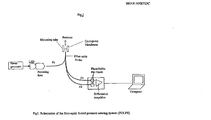
- Fig. 1 is a drawing of the fiber-optic linked pressure sensing system.
- three optical fibers constructed of conventional materials are contained within a catheter with an outside diameter of 1.5 mm.
- a corrugated polymer membrane, 1 mm in diameter, is mounted on the probe end of the tube.
- One of the optical fibers, the illuminating fiber is coupled to a light-emitting diode (LED) system through a fiber-optic coupling lens.
- the other two fibers, the detecting fibers are each coupled to a PIN photodiode diode.
- the two PIN diodes are connected to a differential amplifier with high common mode rejection ratio, whose output is sent to a display system.
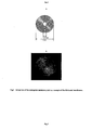
- Fig. 2 is a drawing of the corrugated membrane that is mounted on the end of the catheter.
- the membrane is 1 mm in diameter, 1 ⁇ m thick, has a 5 ⁇ m corrugation height, and a 30 ⁇ m corrugation period. It also has a reflective center in the range 100-200 ⁇ m in diameter and a pressure range of 0 to 10 cm H 2 O with a resolution of 0.1 mm H 2 O.
- the exposed surfaces of the corrugated membrane comprise any suitable polymer, as for example, a spincoatable polymer such as parylene.
- the parylene-platinum-parylene membrane is fabricated using the following microelectromechanical system (MEMS) fabrication protocol.
- MEMS microelectromechanical system
- a clean 3" silicon substrate is used.
- Positive photo-resist of 5 ⁇ m thickness is deposited as substrate by spin-coating (Shipley 1818 ) at 500 rpm for 45 seconds, then at 4000 rpm for 5 seconds. Hardening is accomplished by baking the sample for 5 minutes at 90°C. A chrome corrugated membrane mask is then overlaid on the top of the photoresist.
- the pattern is generated by exposing the substrate to 405 nm UV irradiation for 18 seconds at 20 mW.
- the membrane pattern is developed by agitation in 20% shipley 351 .
- a 0.5 ⁇ m parylene film is deposited again on the top of the photoresist.
- a 0.1 ⁇ m platinum film is deposited on the top of the parylene.
- a second layer of 0.5 ⁇ m parylene is then deposited.
- the membrane is released by 3-4 hrs slow agitation in acetone.
- An example of such a fabricated corrugated membrane is shown in Fig. 2 .
- Fig. 3a is a drawing of the three fibers in the fiber-optic bundle.
- the fibers have a core diameter of 200 microns, and a low refractive-index cladding 225 microns thick.
- Fig. 3b shows a preferred arrangement of the fibers that yields an optimal signal to noise ratio. They are arranged so that the end of the illuminating fiber is 800-900 microns from the corrugated membrane, while the two detecting fibers are, respectively, 400 microns and 1000 microns from the corrugated membrane. The displacement of the reflecting membrane is derived from the differences between the light signals received by the two detecting fibers.
- Fig. 4 is an example of an experiment in which the catheter tip measured the pressure of water of varying depth.
- Fig. 4a and 4b show the sensitivity of the sensor over different ranges of pressure.
- Fig. 4a shows the sensitivity in percent change over the range 1-8 cm H 2 O.
- Fig. 4b shows the sensitivity in percent change over the range 1-11 mm H 2 O.
- the normalized signal from the differential analyzer is plotted against the depth of the water when pressure is increased (adding water) or decreased (withdrawing water). From Fig. 4b , the average sensitivity of the device was 1.2% change per 1 mm H 2 O pressure change for both increasing and decreasing pressures.
- Fig. 5a is a photograph of an experiment utilizing the present invention.
- a rat was anesthetized using IM ketamine (44 mg/kg) and intubated with an endotracheal tube.
- the fiber-optics probe was advanced through the endotracheal tube into the lumen of the trachea.
- the light source was a 590 nm LED with its luminosity adjusted to a level consistent with the dynamic range of the PIN detector.
- Baseline pressures were recorded first. Neostigmine, an anti-cholinesterase agent was injected intraperitoneally and pressures were monitored for several minutes. At the end of the experiment, a tracheotomy was performed to independently determine the tracheal pressure as shown in Fig 5b .
- Fig. 6 contains graphs of the pressure readings obtained in the experiment shown in Fig. 5 and described above.
- the anesthetized rat breathed at 120 breaths/min. Two minutes following injection of neostigmine, the rat exhibited a period doubling breathing pattern. Approximately 5 minutes later, apnea was induced and the rat's breathing gradually returned to normal.
- the system and method of the present invention finds particular application for the physiological monitoring of pressure in small laboratory animals.
- it is useful for detailed monitoring of intrapulmonary pressure such as the respiratory rate, inspiratory time, expiratory time, tidal volume and peak inspiratory pressure and how they may change in response to environmental insults, drugs, or pathological conditions.
- the system and method of the present invention provides a new tool for studying the physiological response of laboratory animals and could find application in clinical monitoring of patients as well.
Landscapes
- Health & Medical Sciences (AREA)
- Life Sciences & Earth Sciences (AREA)
- Physics & Mathematics (AREA)
- Medical Informatics (AREA)
- Surgery (AREA)
- Veterinary Medicine (AREA)
- Public Health (AREA)
- Biophysics (AREA)
- Pathology (AREA)
- Engineering & Computer Science (AREA)
- Biomedical Technology (AREA)
- Heart & Thoracic Surgery (AREA)
- General Health & Medical Sciences (AREA)
- Molecular Biology (AREA)
- Animal Behavior & Ethology (AREA)
- Cardiology (AREA)
- Vascular Medicine (AREA)
- General Physics & Mathematics (AREA)
- Physiology (AREA)
- Spectroscopy & Molecular Physics (AREA)
- Optics & Photonics (AREA)
- Measuring Fluid Pressure (AREA)
- Measuring Pulse, Heart Rate, Blood Pressure Or Blood Flow (AREA)
- Measuring And Recording Apparatus For Diagnosis (AREA)
Claims (10)
- Ein System zur Überwachung niedriger dynamischer Drücke in begrenzten Räumen, wobei ein solches System Folgendes umfasst:einen Katheter,eine mehrschichtige gewellte Membran mit einem Durchmesser von weniger als 2 mm mit einer reflektierenden inneren Schicht, die in dem Katheter angebracht ist,einen Satz Glasfasern, die eine oder mehrere Beleuchtungsfasern und zwei oder mehr Erfassungsfasern umfassen, die in dem Katheter enthalten sind und deren Enden sich in verschiedenen Abständen von der Membran befinden,ein Beleuchtungssystem, das mit den Beleuchtungsfasern gekoppelt ist, undein Erfassungssystem, das mit den Beleuchtungsfasern gekoppelt ist.
- Das System gemäß Anspruch 1, worin die gewellte Membran ein Minimum von 30 Wellungsperioden umfasst, wobei die Wellungstiefe nicht mehr als 5 µm beträgt.
- Das System gemäß Anspruch 1, worin die gewellte Membran einen Druckbereich von 0 bis 10 cm H2O mit einer Auflösung von 0,1 mm H2O hat.
- Das System gemäß Anspruch 1, worin die frei liegenden Oberflächen der gewellten Membran aus Polymer bestehen.
- Das System gemäß Anspruch 1, worin die gewellte Membran drei Schichten hat.
- Das System gemäß Anspruch 5, worin die mittlere Schicht der gewellten Membran aus Material mit guten reflektierenden optischen Eigenschaften bei sichtbaren Wellenlängen von Licht besteht.
- Das System gemäß Anspruch 1, worin das Beleuchtungssystem eine oder mehrere Leuchtdioden umfasst.
- Das System gemäß Anspruch 1, worin das Erfassungssystem eine oder mehrere PIN-Dioden umfasst.
- Das System gemäß Anspruch 1, worin das Erfassungssystem einen linearen Differentialverstärker mit hoher Verstärkung und großem Gleichtaktunterdrückungsverhältnis umfasst.
- Das System gemäß Anspruch 1, worin das System frei von magnetischer und elektrischer Interferenz vom Messbereich ist.
Applications Claiming Priority (3)
| Application Number | Priority Date | Filing Date | Title |
|---|---|---|---|
| US44972103P | 2003-02-24 | 2003-02-24 | |
| US449721P | 2003-02-24 | ||
| PCT/US2004/004942 WO2004075717A2 (en) | 2003-02-24 | 2004-02-19 | A miniature optically coupled electrically isolated ultrasensitive dynamic pressure detector |
Publications (3)
| Publication Number | Publication Date |
|---|---|
| EP1599711A2 EP1599711A2 (de) | 2005-11-30 |
| EP1599711A4 EP1599711A4 (de) | 2009-04-29 |
| EP1599711B1 true EP1599711B1 (de) | 2010-04-14 |
Family
ID=32927551
Family Applications (1)
| Application Number | Title | Priority Date | Filing Date |
|---|---|---|---|
| EP04712901A Expired - Lifetime EP1599711B1 (de) | 2003-02-24 | 2004-02-19 | Optisch gekoppelter, elektrisch isolierter ultraempfindlicher dynamischer miniaturdrucksensor |
Country Status (5)
| Country | Link |
|---|---|
| US (1) | US7392707B2 (de) |
| EP (1) | EP1599711B1 (de) |
| JP (1) | JP2006518639A (de) |
| DE (1) | DE602004026560D1 (de) |
| WO (1) | WO2004075717A2 (de) |
Families Citing this family (4)
| Publication number | Priority date | Publication date | Assignee | Title |
|---|---|---|---|---|
| JP2007053147A (ja) * | 2005-08-16 | 2007-03-01 | Sony Corp | 有機半導体装置及びその製造方法 |
| CA2916685A1 (en) * | 2013-06-27 | 2014-12-31 | Minipumps, Llc | Method of making a corrugated deflection diaphragm |
| US10973586B2 (en) | 2016-01-19 | 2021-04-13 | Verum Tcs, Llc | Systems and methods of determining one or more properties of a catheter and a distal tip thereof |
| EP3865453A1 (de) * | 2020-02-13 | 2021-08-18 | Miraex SA | Mikro-opto-mechanischer systemsensor, anordnung und herstellungsverfahren |
Family Cites Families (7)
| Publication number | Priority date | Publication date | Assignee | Title |
|---|---|---|---|---|
| CH639196A5 (de) * | 1977-11-23 | 1983-10-31 | Asea Ab | Messgeraet zum messen von physikalischen groessen mittels optischer mittel. |
| US4703757A (en) * | 1984-11-16 | 1987-11-03 | Cordis Corporation | Optical fiber pressure transducer |
| US5142155A (en) * | 1991-03-11 | 1992-08-25 | Hewlett-Packard Company | Catheter tip fluorescence-quenching fiber optic pressure sensor |
| US6238339B1 (en) * | 1991-06-20 | 2001-05-29 | Instrumentarium Corp. | Remote sensing tonometric catheter apparatus and method |
| US6272370B1 (en) * | 1998-08-07 | 2001-08-07 | The Regents Of University Of Minnesota | MR-visible medical device for neurological interventions using nonlinear magnetic stereotaxis and a method imaging |
| US6537232B1 (en) * | 1997-05-15 | 2003-03-25 | Regents Of The University Of Minnesota | Intracranial pressure monitoring device and method for use in MR-guided drug delivery |
| US6820487B2 (en) * | 2000-03-07 | 2004-11-23 | Masayoshi Esahi | Reflective moveable diaphragm unit and pressure sensor containing same |
-
2004
- 2004-02-19 DE DE602004026560T patent/DE602004026560D1/de not_active Expired - Lifetime
- 2004-02-19 WO PCT/US2004/004942 patent/WO2004075717A2/en not_active Ceased
- 2004-02-19 US US10/546,966 patent/US7392707B2/en not_active Expired - Fee Related
- 2004-02-19 EP EP04712901A patent/EP1599711B1/de not_active Expired - Lifetime
- 2004-02-19 JP JP2006503717A patent/JP2006518639A/ja not_active Withdrawn
Also Published As
| Publication number | Publication date |
|---|---|
| US7392707B2 (en) | 2008-07-01 |
| US20060225510A1 (en) | 2006-10-12 |
| WO2004075717A2 (en) | 2004-09-10 |
| EP1599711A2 (de) | 2005-11-30 |
| EP1599711A4 (de) | 2009-04-29 |
| JP2006518639A (ja) | 2006-08-17 |
| DE602004026560D1 (de) | 2010-05-27 |
| WO2004075717A3 (en) | 2005-05-06 |
Similar Documents
| Publication | Publication Date | Title |
|---|---|---|
| JP2590382Y2 (ja) | 血液パラメータの光学的検出用組立体 | |
| Togawa et al. | Biomedical transducers and instruments | |
| US6868736B2 (en) | Ultra-miniature optical pressure sensing system | |
| US5280786A (en) | Fiberoptic blood pressure and oxygenation sensor | |
| Mansouri et al. | A miniature optical glucose sensor based on affinity binding | |
| US8224410B2 (en) | Dermally affixed sensor device | |
| EP0455715A1 (de) | Lichtleiter-druckwandler zur messung in blutgefässen | |
| US20120271131A1 (en) | Mucosal sensor for the assessment of tissue and blood constituents and technique for using the same | |
| WO1992018887A1 (en) | Compound optical probe employing single optical waveguide | |
| CN102499665B (zh) | 一种基于光纤传感的微型颅内多参数传感器 | |
| AU756142B2 (en) | Apparatus and method for measuring pulse transit time | |
| Liang et al. | Wearable and multifunctional self-mixing microfiber sensor for human health monitoring | |
| US20140275950A1 (en) | Imaging guidewire with pressure sensing | |
| JP2010506139A (ja) | 光学圧力変換器を有する気道アダプタ及びセンサ素子を製造する方法 | |
| JPS6354146A (ja) | 圧力モニタ装置 | |
| CN113784663A (zh) | 穿刺装置、包括该穿刺装置的穿刺系统及其方法 | |
| EP1599711B1 (de) | Optisch gekoppelter, elektrisch isolierter ultraempfindlicher dynamischer miniaturdrucksensor | |
| Goodyer et al. | The design of an optical fiber pressure transducer for use in the upper airways | |
| Seo et al. | Tapered fiber optic sensor for arterial pulse wave monitoring | |
| EP3177909B1 (de) | Kapnografiesystem | |
| GB2308888A (en) | Blood pressure measuring device | |
| JP3475205B2 (ja) | 観血式直接血圧計 | |
| EP0205531A1 (de) | Faseroptikwandler | |
| CN222357599U (zh) | 可监测卧床病人生命体征参数的光纤监护仪 | |
| CN121265037B (zh) | 一种用于手术麻醉的植入式血药浓度实时监测设备 |
Legal Events
| Date | Code | Title | Description |
|---|---|---|---|
| PUAI | Public reference made under article 153(3) epc to a published international application that has entered the european phase |
Free format text: ORIGINAL CODE: 0009012 |
|
| 17P | Request for examination filed |
Effective date: 20050914 |
|
| AK | Designated contracting states |
Kind code of ref document: A2 Designated state(s): AT BE BG CH CY CZ DE DK EE ES FI FR GB GR HU IE IT LI LU MC NL PT RO SE SI SK TR |
|
| AX | Request for extension of the european patent |
Extension state: AL LT LV MK |
|
| DAX | Request for extension of the european patent (deleted) | ||
| RBV | Designated contracting states (corrected) |
Designated state(s): DE FR GB IT |
|
| A4 | Supplementary search report drawn up and despatched |
Effective date: 20090331 |
|
| RIC1 | Information provided on ipc code assigned before grant |
Ipc: A61B 5/0215 20060101ALI20090325BHEP Ipc: G01L 9/00 20060101AFI20050513BHEP |
|
| GRAP | Despatch of communication of intention to grant a patent |
Free format text: ORIGINAL CODE: EPIDOSNIGR1 |
|
| GRAS | Grant fee paid |
Free format text: ORIGINAL CODE: EPIDOSNIGR3 |
|
| GRAA | (expected) grant |
Free format text: ORIGINAL CODE: 0009210 |
|
| AK | Designated contracting states |
Kind code of ref document: B1 Designated state(s): DE FR GB IT |
|
| REG | Reference to a national code |
Ref country code: GB Ref legal event code: FG4D |
|
| REF | Corresponds to: |
Ref document number: 602004026560 Country of ref document: DE Date of ref document: 20100527 Kind code of ref document: P |
|
| RIN2 | Information on inventor provided after grant (corrected) |
Inventor name: YEATES, DONOVAN, B. Inventor name: HESKETH, PETER Inventor name: KIM, SANGKYUNG Inventor name: WONG, LID, B. Inventor name: MAO, HUA |
|
| RAP2 | Party data changed (patent owner data changed or rights of a patent transferred) |
Owner name: YEATES, DONOVAN B. |
|
| REG | Reference to a national code |
Ref country code: GB Ref legal event code: 732E Free format text: REGISTERED BETWEEN 20110120 AND 20110126 |
|
| PLBE | No opposition filed within time limit |
Free format text: ORIGINAL CODE: 0009261 |
|
| STAA | Information on the status of an ep patent application or granted ep patent |
Free format text: STATUS: NO OPPOSITION FILED WITHIN TIME LIMIT |
|
| 26N | No opposition filed |
Effective date: 20110117 |
|
| PG25 | Lapsed in a contracting state [announced via postgrant information from national office to epo] |
Ref country code: IT Free format text: LAPSE BECAUSE OF FAILURE TO SUBMIT A TRANSLATION OF THE DESCRIPTION OR TO PAY THE FEE WITHIN THE PRESCRIBED TIME-LIMIT Effective date: 20100414 |
|
| REG | Reference to a national code |
Ref country code: DE Ref legal event code: R081 Ref document number: 602004026560 Country of ref document: DE Owner name: YEATES, DONOVAN B., ESCONDIDO, US Free format text: FORMER OWNER: BIO TECHPLEX CORP., GROVE VILLAGE, ILL., US Effective date: 20110302 Ref country code: DE Ref legal event code: R081 Ref document number: 602004026560 Country of ref document: DE Owner name: YEATES, DONOVAN B., US Free format text: FORMER OWNER: BIO TECHPLEX CORP., GROVE VILLAGE, US Effective date: 20110302 |
|
| REG | Reference to a national code |
Ref country code: FR Ref legal event code: PLFP Year of fee payment: 13 |
|
| REG | Reference to a national code |
Ref country code: FR Ref legal event code: PLFP Year of fee payment: 14 |
|
| PGFP | Annual fee paid to national office [announced via postgrant information from national office to epo] |
Ref country code: FR Payment date: 20170330 Year of fee payment: 14 |
|
| PGFP | Annual fee paid to national office [announced via postgrant information from national office to epo] |
Ref country code: GB Payment date: 20170327 Year of fee payment: 14 |
|
| PGFP | Annual fee paid to national office [announced via postgrant information from national office to epo] |
Ref country code: DE Payment date: 20170330 Year of fee payment: 14 |
|
| REG | Reference to a national code |
Ref country code: DE Ref legal event code: R119 Ref document number: 602004026560 Country of ref document: DE |
|
| GBPC | Gb: european patent ceased through non-payment of renewal fee |
Effective date: 20180219 |
|
| REG | Reference to a national code |
Ref country code: FR Ref legal event code: ST Effective date: 20181031 |
|
| PG25 | Lapsed in a contracting state [announced via postgrant information from national office to epo] |
Ref country code: DE Free format text: LAPSE BECAUSE OF NON-PAYMENT OF DUE FEES Effective date: 20180901 |
|
| PG25 | Lapsed in a contracting state [announced via postgrant information from national office to epo] |
Ref country code: GB Free format text: LAPSE BECAUSE OF NON-PAYMENT OF DUE FEES Effective date: 20180219 Ref country code: FR Free format text: LAPSE BECAUSE OF NON-PAYMENT OF DUE FEES Effective date: 20180228 |