EP1599692B1 - Verteiler mit einem körper mit einer konischen innenfläche, so dass die querschnittsfläche in strömungsrichtung abnimmt - Google Patents
Verteiler mit einem körper mit einer konischen innenfläche, so dass die querschnittsfläche in strömungsrichtung abnimmt Download PDFInfo
- Publication number
- EP1599692B1 EP1599692B1 EP04716255A EP04716255A EP1599692B1 EP 1599692 B1 EP1599692 B1 EP 1599692B1 EP 04716255 A EP04716255 A EP 04716255A EP 04716255 A EP04716255 A EP 04716255A EP 1599692 B1 EP1599692 B1 EP 1599692B1
- Authority
- EP
- European Patent Office
- Prior art keywords
- manifold
- branch
- coning angle
- cross
- wall
- Prior art date
- Legal status (The legal status is an assumption and is not a legal conclusion. Google has not performed a legal analysis and makes no representation as to the accuracy of the status listed.)
- Expired - Lifetime
Links
Images

Classifications
-
- F—MECHANICAL ENGINEERING; LIGHTING; HEATING; WEAPONS; BLASTING
- F24—HEATING; RANGES; VENTILATING
- F24D—DOMESTIC- OR SPACE-HEATING SYSTEMS, e.g. CENTRAL HEATING SYSTEMS; DOMESTIC HOT-WATER SUPPLY SYSTEMS; ELEMENTS OR COMPONENTS THEREFOR
- F24D3/00—Hot-water central heating systems
- F24D3/10—Feed-line arrangements, e.g. providing for heat-accumulator tanks, expansion tanks ; Hydraulic components of a central heating system
- F24D3/1058—Feed-line arrangements, e.g. providing for heat-accumulator tanks, expansion tanks ; Hydraulic components of a central heating system disposition of pipes and pipe connections
- F24D3/1066—Distributors for heating liquids
-
- F—MECHANICAL ENGINEERING; LIGHTING; HEATING; WEAPONS; BLASTING
- F16—ENGINEERING ELEMENTS AND UNITS; GENERAL MEASURES FOR PRODUCING AND MAINTAINING EFFECTIVE FUNCTIONING OF MACHINES OR INSTALLATIONS; THERMAL INSULATION IN GENERAL
- F16L—PIPES; JOINTS OR FITTINGS FOR PIPES; SUPPORTS FOR PIPES, CABLES OR PROTECTIVE TUBING; MEANS FOR THERMAL INSULATION IN GENERAL
- F16L41/00—Branching pipes; Joining pipes to walls
- F16L41/02—Branch units, e.g. made in one piece, welded, riveted
- F16L41/03—Branch units, e.g. made in one piece, welded, riveted comprising junction pieces for four or more pipe members
-
- F—MECHANICAL ENGINEERING; LIGHTING; HEATING; WEAPONS; BLASTING
- F16—ENGINEERING ELEMENTS AND UNITS; GENERAL MEASURES FOR PRODUCING AND MAINTAINING EFFECTIVE FUNCTIONING OF MACHINES OR INSTALLATIONS; THERMAL INSULATION IN GENERAL
- F16L—PIPES; JOINTS OR FITTINGS FOR PIPES; SUPPORTS FOR PIPES, CABLES OR PROTECTIVE TUBING; MEANS FOR THERMAL INSULATION IN GENERAL
- F16L47/00—Connecting arrangements or other fittings specially adapted to be made of plastics or to be used with pipes made of plastics
- F16L47/26—Connecting arrangements or other fittings specially adapted to be made of plastics or to be used with pipes made of plastics for branching pipes; for joining pipes to walls; Adaptors therefor
- F16L47/32—Branch units, e.g. made in one piece, welded, riveted
-
- Y—GENERAL TAGGING OF NEW TECHNOLOGICAL DEVELOPMENTS; GENERAL TAGGING OF CROSS-SECTIONAL TECHNOLOGIES SPANNING OVER SEVERAL SECTIONS OF THE IPC; TECHNICAL SUBJECTS COVERED BY FORMER USPC CROSS-REFERENCE ART COLLECTIONS [XRACs] AND DIGESTS
- Y10—TECHNICAL SUBJECTS COVERED BY FORMER USPC
- Y10T—TECHNICAL SUBJECTS COVERED BY FORMER US CLASSIFICATION
- Y10T137/00—Fluid handling
- Y10T137/206—Flow affected by fluid contact, energy field or coanda effect [e.g., pure fluid device or system]
- Y10T137/2229—Device including passages having V over T configuration
- Y10T137/224—With particular characteristics of control input
Definitions
- the invention relates to a manifold comprising a body with a plurality of branch fittings diverging therefrom.
- a manifold is used in pipeworks at points where liquid flowing in a pipework is conveyed from a main pipe to branch pipes.
- a manifold comprises a body including several branch fittings. Liquid is conveyed to the manifold along a main pipe while the branch fittings are provided with branch pipes, the manifold thus enabling the liquid to be divided from the main pipe into the several branch pipes.
- a manifold is used e.g. in tap water systems and heating systems, such as in floor heating systems.
- Application FI 20012460 discloses a bypass manifold manufactured e.g. from plastic.
- a connecting piece can be arranged in the branch fittings of the bypass manifold, which comprises a means for locking the connecting pieces in place, the locking means comprising one or more parts.
- the publication discloses a bypass manifold whose structure forms a modular system, enabling the body of the bypass manifold to be provided with different connecting pieces and the connecting pieces to be locked in place tightly and reliably.
- Such a bypass manifold is extremely versatile, enabling e.g. branch pipes of different sizes and even of different materials to be connected to the same bypass manifold by means of a connecting piece.
- BE 790869 discloses a manifold comprising the features of the preamble of claim 1.
- An object of the present invention is to provide a novel and improved manifold.
- the manifold of the invention is characterized by the features of claim 1.
- the idea underlying the invention is that the manifold can be easily installed by simply pressing it in place in the case an installation cabinet or room, e.g. a wall, has been provided with fasteners for the ribs.
- the idea underlying an embodiment is that a wall of the body of the manifold is substantially equally thick throughout, which means that the outer surface of the body of the manifold is also substantially conical. The amount of material to be used for the manifold is then reduced considerably, thus enabling material savings to be achieved while manufacturing the manifold. Furthermore, while manufacturing a manifold by die-casting, the manifold is thoroughly and uniformly cooled down, which means that no additional stress appears inside the material.
- a second embodiment is that the convergent angle of the outer surface of the body of the manifold is larger than the convergent angle of the inner surface.
- the wall of the manifold is then thinner at the rear end of the manifold than at the front end thereof. In such a case in particular it is possible to save in the amount of material.
- the strength of the manifold can still be kept sufficient.
- An embodiment is that the ratio of the outer diameter of the body of the manifold to the thickness of the wall is constant all the time. The thickness of the wall is thus at its thinnest when the outer diameter is at its smallest.
- the inner diameter of the body of the manifold at the rear end of the manifold is arranged to be equal in size to the inner diameter of the last branch fitting. This enables the amount of material necessary for the structure of the manifold and the flow of liquid inside the manifold to be optimized.
- Figure 1 shows a manifold 1.
- the manifold 1 comprises a body 2 and a plurality of branch fittings 3 arranged to diverge from the body 2.
- the number of branch fittings 3 may vary as necessary. Typically, at least three branch fittings 3 are provided.
- the number of branch fittings 3 may vary e.g. between three and five.
- the diameters of the branch fittings 3 may be equal in size or a branch fitting or some branch fittings may have larger diameters than the others.
- the branch fittings 3 may be located at regular distances from each other or the distance between the branch fittings 3 may vary.
- the first branch fitting 3 in the direction of flow of liquid has the largest outer and inner diameter.
- the distance between the first and the second branch fitting is also larger than the distance between the other branch fittings; this is to provide enough room for installation around the branch fitting 3 with the largest diameter.
- a main pipe is arranged in the manifold 1 in a right-hand fitting of the manifold 1.
- the manifold 1 is closed at its one end, i.e. only one main pipe and branch pipes are connected to the manifold 1. No ongoing main pipe is thus connected to the particular manifold.
- the manifold 1 has thus, while being manufactured, already been provided with a closed end, so it does not have to be plugged at the end.
- the closing end of the body 2 of the manifold can then be curved at its top corner, which is advantageous for the flow of liquid.
- the branch pipes to be connected to the manifold 1 are thus such that the diameter of one branch pipe is larger than the diameter of the other three branch pipes to be connected to the manifold 1. If no branch pipe is to be connected to the branch fitting 3, it can be plugged.
- Liquid is arranged to flow from the main pipe to the branch pipes.
- the inner surface of the manifold 1 is conically convergent. Consequently, at the end where the main pipe is to be connected, the inner diameter of the manifold 1 is larger than at the opposite end.
- the manifold 1 converges such that the coning angle ⁇ of the inner surface of the body 2 is e.g. at least 2°.
- the coning angle ⁇ may vary e.g. between 2° and 10°.
- the coning angle varies between 3° and 8°.
- a preferred embodiment is that the coning angle ⁇ is 5°.
- the wall of the body 2 of the manifold 1 is substantially equally thick throughout, which means that the shape of the outer surface of the body 2 thus also resembles a convergent cone and the coning angle of the outer surface is substantially equal in size to the coning angle of the inner surface. If desired, the coning angle of the outer surface can also be made larger than the coning angle of the inner surface.
- the thickness of the body 2 of the manifold 1 is then smaller at the rear end than at the front end thereof. When the diameter of the body 2 of the manifold is at its smallest, the thickness of the wall does not have to be as large as at the largest diameter and yet the structure of the manifold can be made strong enough.
- An embodiment is to make the structure of the manifold 1 such that the ratio of the outer diameter of the body 2 of the manifold to the wall thickness remains substantially constant.
- the inner diameter of the manifold 1 is convergent such that at the rear end, i.e. at the closing end, of the manifold 1, the inner diameter of the body 2 is equal in size to the inner diameter of the last branch fitting 3.
- the flow of liquid inside the manifold can be divided in an optimal manner.
- this branch fitting with the larger diameter is arranged at the front end of the manifold, i.e. closest to the main pipe.
- the outer surface of the body 2 of the manifold 1 is provided with ribs 4 around the body 2.
- the outer diameters of the ribs 4 are all substantially equal in size, i.e. at the front end of the manifold 1 the height of the ribs 4 from the outer surface of the body 2 is smaller than that at the closing end of the manifold 1. This enables the ribs 4 to be readily utilized while attaching the manifold in place.
- the manifold 1 can be attached in place e.g. such that at the location where the manifold is to be placed, e.g. in an installation cabinet or room, e.g. a wall has been provided with fasteners for the ribs 4.
- the manifold 1 can simply be pressed in place such that the ribs fasten to a fastener equipped with jaws.
- the ribs 4 also stiffen the structure of the body 2 such that the wall of the body 2 does not have to be very thick.
- the main pipe and the branch pipes can be attached to the body 2 of the manifold and to the branch fittings 3 e.g. by push-pull coupling and/or using clamping rings.
- the connections can also be implemented by means of thread joints or in some other manner.
- Figure 2 is a side view showing the manifold 1.
- Figure 2 also shows stopping projections 5.
- the purpose of the stopping projections 5 is to stop the main pipe to be inserted into the body of the manifold or the branch pipes to be inserted into the branch fitting 3 at their correct place.
- the manifold shown in the figure is particularly advantageously suited for use in tap water systems.
- the manifold must then be able to resist a temperature of 95° temporarily and a temperature of 70° for a period of fifty years.
- the manifold 1 is manufactured from plastic by die-casting.
- the manifold may then be manufactured e.g. from polyphenyl sulfone PPSU, polysulphone PSU, polyvinylidene fluoride PVDF, glass fibre reinforced polyamide PA, or cross-linked polyolefin plastic, such as cross-linked polyethylen PEX. It is also possible to use other appropriate materials.
- Figure 2 also shows, by a broken line, a fastening part 6.
- the fastening part 6 has an opening constituting a slot 7.
- the manifold 1 can be fastened in place by arranging a screw or screws through the slot 7.
- the slot 7 enables the manifold 1 to be able to move in an axial direction, which movement in the axial direction may be caused e.g. by thermal expansion.
- the fastening part 6 is arranged between two branch fittings 3. If desired, the fastening part 6 may be fastened e.g. only to one of the branch fittings, or to the body of the manifold.
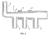
- Figure 3 shows a manifold 1 whose last branch fitting 3 diverges from the body 2 180° in a different direction than the rest of the branch fittings 3.
- the manifold can also be formed such that one or more branch fittings diverges e.g. 90° in a different direction than the rest of the branch fittings.
- other diverging directions are also possible.
- the rear end of the manifold 1 is further formed such that the connection of the last branch fitting to the body 2 forms a bend of rather a large curvature.
- the radius of curvature of the eternal angle of the particular bend is e.g. 6-60 mm when the inner diameter of the branch fitting is about 10 mm. The flow can then be made very smooth.
- the coning angle of the inner surface of the manifold 1 does not necessarily continuously have to be equal in size.
- the manifold can be formed e.g. such that the coning angle of the inner surface is larger at the front end than at the rear end thereof.
- the coning angles can be formed to change such that at the front end of the manifold the coning angle is smaller while at the rear end of the manifold the coning angle is larger.
- the coning angle may change more often than once along the manifold.
- coning angle of the manifold may also be straight, i.e. its coning angle at the particular point is then about 0°.
- the coning angle of the outer surface may also change in a similar manner.
Landscapes
- Engineering & Computer Science (AREA)
- General Engineering & Computer Science (AREA)
- Mechanical Engineering (AREA)
- Thermal Sciences (AREA)
- Chemical & Material Sciences (AREA)
- Combustion & Propulsion (AREA)
- Physics & Mathematics (AREA)
- Branch Pipes, Bends, And The Like (AREA)
- Extrusion Moulding Of Plastics Or The Like (AREA)
- Pens And Brushes (AREA)
- Vaporization, Distillation, Condensation, Sublimation, And Cold Traps (AREA)
- Pipe Accessories (AREA)
- Treatment Of Water By Ion Exchange (AREA)
- Injection Moulding Of Plastics Or The Like (AREA)
- Laminated Bodies (AREA)
- Rigid Pipes And Flexible Pipes (AREA)
- Spinning Methods And Devices For Manufacturing Artificial Fibers (AREA)
- Infusion, Injection, And Reservoir Apparatuses (AREA)
- Exhaust Silencers (AREA)
Claims (10)
- Ein Verteiler umfassend einen Körper (2) mit mehreren Abzweig-Fittingen (3) ausgehend hiervon, wobei die Innenfläche des Körpers (2) konisch ausgebildet ist, so dass die innere Querschnittsfläche des Körpers (2) in Durchflussrichtung abnimmt, und die Außenfläche des Körpers (2) ebenfalls konisch ausgebildet ist, dadurch gekennzeichnet, dass der Verteiler den Körper (2) umschließende Rippen (4) aufweist, wobei die Rippen (4), unabhängig vom Außen- oder Innendurchmesser des Körpers (2), den gleichen Außendurchmesser haben.
- Ein Verteiler nach Anspruch 1, dadurch gekennzeichnet, dass der Konuswinkel (α) der Innenfläche des Köpers (2) des Verteilers (1) im Wesentlichen die gleiche Größe wie der Konuswinkel der Außenfläche des Körpers (2) des Verteilers (1) aufweist, wobei eine Wandung des Körpers (2) im Wesentlichen durchgehend die gleiche Stärke besitzt.
- Ein Verteiler nach Anspruch 1, dadurch gekennzeichnet, dass der Konuswinkel der Außenfläche des Körpers (2) des Verteilers (1) größer ist als der Konuswinkel (α) der Innenfläche des Körpers (2) des Verteilers (1), wobei die Wandung des Körpers (2) am hinteren Abschnitt des Verteilers (1) dünner ist als am vorderen Abschnitt.
- Ein Verteiler nach Anspruch 3, dadurch gekennzeichnet, dass das Größenverhältnis des Außendurchmessers des Körpers (2) des Verteilers (1) zur Wandstärke des Körpers (2) im Wesentlichen im gesamten Körper (2) des Verteilers (1) gleich bleibt.
- Ein Verteiler nach einem der vorangegangenen Ansprüche, dadurch gekennzeichnet, dass der Konuswinkel (α) der Innenfläche des Körpers (2) mindestens 2° aufweist.
- Ein Verteiler nach einem der vorangegangenen Ansprüche, dadurch gekennzeichnet, dass der Innendurchmesser des Körpers (2) des Verteilers (1) am hinteren Ende des Verteilers (1) im Wesentlichen die gleiche Größe wie der Innendurchmesser des letzten Abzweig-Fitting (3) besitzt.
- Ein Verteiler nach einem der vorangegangenen Ansprüche, dadurch gekennzeichnet, dass der Körper (2) am hinteren Ende geschlossen ist.
- Ein Verteiler nach einem der vorangegangenen Ansprüche, dadurch gekennzeichnet, dass der Verteiler (1) ein Befestigungsteil (6) mit einem Schlitz (7) zur Befestigung des Verteilers (1) aufweist.
- Ein Verteiler nach einem der vorangegangenen Ansprüche, dadurch gekennzeichnet, dass der Verteiler (1) als Verteiler eines Leitungswassersystems dient.
- Ein Verteiler nach einem der vorangegangenen Ansprüche, dadurch gekennzeichnet, dass der Verteiler (1) aus Polyphenylsulfon PPSU, Polysulfon PSU, Polyvinylidenfluorid PVDF, glasfaserverstärktem Polyamid PA oder vernetztem Polyolefin hergestellt wird.
Priority Applications (1)
| Application Number | Priority Date | Filing Date | Title |
|---|---|---|---|
| PL04716255T PL1599692T3 (pl) | 2003-03-03 | 2004-03-02 | Przewód rurowy rozgałęziony zawierający korpus ze stożkową powierzchnią wewnętrzną, taką, że pole przekroju zmniejsza się w kierunku przepływu |
Applications Claiming Priority (3)
| Application Number | Priority Date | Filing Date | Title |
|---|---|---|---|
| FI20030329A FI115852B (fi) | 2003-03-03 | 2003-03-03 | Jakotukki |
| FI20030329 | 2003-03-03 | ||
| PCT/FI2004/000112 WO2004079250A1 (en) | 2003-03-03 | 2004-03-02 | Manifold comprising a body with a conical inner surface such that the cross-sectional area decreases in the direction of flow |
Publications (2)
| Publication Number | Publication Date |
|---|---|
| EP1599692A1 EP1599692A1 (de) | 2005-11-30 |
| EP1599692B1 true EP1599692B1 (de) | 2010-05-12 |
Family
ID=8565761
Family Applications (1)
| Application Number | Title | Priority Date | Filing Date |
|---|---|---|---|
| EP04716255A Expired - Lifetime EP1599692B1 (de) | 2003-03-03 | 2004-03-02 | Verteiler mit einem körper mit einer konischen innenfläche, so dass die querschnittsfläche in strömungsrichtung abnimmt |
Country Status (13)
| Country | Link |
|---|---|
| US (1) | US7726698B2 (de) |
| EP (1) | EP1599692B1 (de) |
| AT (1) | ATE467794T1 (de) |
| CA (1) | CA2516072C (de) |
| DE (1) | DE602004027119D1 (de) |
| DK (1) | DK1599692T3 (de) |
| EA (1) | EA007875B1 (de) |
| ES (1) | ES2343629T3 (de) |
| FI (1) | FI115852B (de) |
| NO (1) | NO20054454L (de) |
| PL (1) | PL1599692T3 (de) |
| PT (1) | PT1599692E (de) |
| WO (1) | WO2004079250A1 (de) |
Families Citing this family (8)
| Publication number | Priority date | Publication date | Assignee | Title |
|---|---|---|---|---|
| DE102007050955B4 (de) * | 2007-10-23 | 2011-05-05 | Henco Industries Nv | Verteileranordnung |
| US10457540B2 (en) | 2010-07-09 | 2019-10-29 | Wayne Fueling Systems Sweden Ab | Kit of parts for assembling a hose connection, a fuel dispensing unit having such a hose connection, and a method for assembling such a hose connection |
| WO2012003885A1 (en) * | 2010-07-09 | 2012-01-12 | Dresser Wayne Ab | A kit of parts for assembling a hose connection, a fuel dispensing unit having such a hose connection, and a method for assembling such a hose connection |
| JP6209531B2 (ja) * | 2011-12-21 | 2017-10-04 | ゼネラル エレクトリック テクノロジー ゲゼルシャフト ミット ベシュレンクテル ハフツングGeneral Electric Technology GmbH | 形状が最適化されたヘッダおよびその製造方法 |
| WO2018169856A1 (en) * | 2017-03-17 | 2018-09-20 | Saint-Gobain Performance Plastics Corporation | Fluid manifold and method of making same |
| WO2019075285A1 (en) * | 2017-10-13 | 2019-04-18 | Saint-Gobain Performance Plastics Corporation | FLUID COLLECTOR AND METHOD FOR MANUFACTURING SUCH FLUID COLLECTOR |
| JP6999177B2 (ja) * | 2018-11-08 | 2022-01-18 | 株式会社不二工機 | 弁装置およびその組立方法 |
| EP4614056A1 (de) * | 2024-03-08 | 2025-09-10 | Robert Bosch GmbH | Verteiler und h2-hochdrucksystem |
Citations (1)
| Publication number | Priority date | Publication date | Assignee | Title |
|---|---|---|---|---|
| WO1987000904A1 (en) * | 1985-07-30 | 1987-02-12 | Oy Uponor Ab | A plastic pipe |
Family Cites Families (15)
| Publication number | Priority date | Publication date | Assignee | Title |
|---|---|---|---|---|
| US884326A (en) * | 1907-06-17 | 1908-04-07 | Mellen N Bray | Means for distributing water to water-jackets of multiple-cylinder engines. |
| US1271779A (en) * | 1917-04-12 | 1918-07-09 | Globe Machine & Stamping Company | Manifold. |
| US1801091A (en) * | 1928-05-22 | 1931-04-14 | Krauss Richard | High-pressure water pipe |
| US2262627A (en) * | 1938-11-15 | 1941-11-11 | Budd Edward G Mfg Co | Manifold |
| US2608819A (en) * | 1946-09-27 | 1952-09-02 | Boeing Co | Collector ring mount |
| FR1107453A (fr) * | 1950-07-01 | 1956-01-03 | Neyrpic Ets | Perfectionnements aux éléments de conduites |
| US3103942A (en) * | 1961-09-22 | 1963-09-17 | Du Pont | Apparatus and process for distributing viscous liquids |
| BE790869A (nl) * | 1972-11-03 | 1973-03-01 | Heating Kits Belgium N V En Ab | Inrichting voor centrale verwarmingsinstallaties. |
| US3794056A (en) * | 1972-11-17 | 1974-02-26 | R Warren | Fluidic pulse and flow divider |
| NO160469C (no) * | 1985-05-31 | 1994-09-23 | Norske Stats Oljeselskap | Y-formet koblingsstykke for sammenkobling av væske-og/eller gassförende rörledninger. |
| US4609009A (en) * | 1985-12-11 | 1986-09-02 | Environmental Elements Corp. | Stepped plenum system |
| JP2001182886A (ja) * | 1999-12-27 | 2001-07-06 | Matsushita Electric Ind Co Ltd | 器具せんの継ぎ手 |
| FI115485B (fi) | 2001-07-06 | 2005-05-13 | Uponor Innovation Ab | Putkiston haarakappale |
| JP2004116601A (ja) * | 2002-09-25 | 2004-04-15 | Nix Inc | ヘッダー |
| DE10330659B3 (de) * | 2003-07-08 | 2004-12-23 | Gea Energietechnik Gmbh | Abdampfleitung für Dampfkraftanlagen |
-
2003
- 2003-03-03 FI FI20030329A patent/FI115852B/fi not_active IP Right Cessation
-
2004
- 2004-03-02 EP EP04716255A patent/EP1599692B1/de not_active Expired - Lifetime
- 2004-03-02 CA CA2516072A patent/CA2516072C/en not_active Expired - Fee Related
- 2004-03-02 PT PT04716255T patent/PT1599692E/pt unknown
- 2004-03-02 WO PCT/FI2004/000112 patent/WO2004079250A1/en not_active Ceased
- 2004-03-02 DE DE200460027119 patent/DE602004027119D1/de not_active Expired - Lifetime
- 2004-03-02 US US10/547,952 patent/US7726698B2/en active Active
- 2004-03-02 ES ES04716255T patent/ES2343629T3/es not_active Expired - Lifetime
- 2004-03-02 DK DK04716255T patent/DK1599692T3/da active
- 2004-03-02 EA EA200501180A patent/EA007875B1/ru not_active IP Right Cessation
- 2004-03-02 PL PL04716255T patent/PL1599692T3/pl unknown
- 2004-03-02 AT AT04716255T patent/ATE467794T1/de active
-
2005
- 2005-09-26 NO NO20054454A patent/NO20054454L/no not_active Application Discontinuation
Patent Citations (1)
| Publication number | Priority date | Publication date | Assignee | Title |
|---|---|---|---|---|
| WO1987000904A1 (en) * | 1985-07-30 | 1987-02-12 | Oy Uponor Ab | A plastic pipe |
Also Published As
| Publication number | Publication date |
|---|---|
| FI115852B (fi) | 2005-07-29 |
| CA2516072A1 (en) | 2004-09-16 |
| PT1599692E (pt) | 2010-07-01 |
| US20070062592A1 (en) | 2007-03-22 |
| DE602004027119D1 (de) | 2010-06-24 |
| EA007875B1 (ru) | 2007-02-27 |
| FI20030329A0 (fi) | 2003-03-03 |
| EA200501180A1 (ru) | 2006-02-24 |
| EP1599692A1 (de) | 2005-11-30 |
| ATE467794T1 (de) | 2010-05-15 |
| WO2004079250A1 (en) | 2004-09-16 |
| ES2343629T3 (es) | 2010-08-05 |
| DK1599692T3 (da) | 2010-08-02 |
| FI20030329L (fi) | 2004-09-04 |
| US7726698B2 (en) | 2010-06-01 |
| PL1599692T3 (pl) | 2010-10-29 |
| CA2516072C (en) | 2011-11-22 |
| NO20054454L (no) | 2005-09-26 |
Similar Documents
| Publication | Publication Date | Title |
|---|---|---|
| US11629485B2 (en) | Flexible drainage trap | |
| US5456499A (en) | Hull fitting | |
| EP1599692B1 (de) | Verteiler mit einem körper mit einer konischen innenfläche, so dass die querschnittsfläche in strömungsrichtung abnimmt | |
| KR20110008334U (ko) | 분기용 배관 | |
| US20150316187A1 (en) | Holding device for pipe joint and pipe joint using same | |
| US20150136267A1 (en) | Single stream discharge drain hose assembly | |
| EP3406956B1 (de) | Abzweigrohr | |
| US20100194101A1 (en) | Swivel joint | |
| RU2564156C2 (ru) | Фиттинг с фланцами для использования с системой герметизации труб | |
| US11644122B2 (en) | Anti-siphon/regulator valve | |
| US7726332B2 (en) | Durable water heating system providing rapid hot water delivery | |
| KR20080002553U (ko) | 걸림테가 구비된 관이음구 | |
| CN214839166U (zh) | 一种便于安装的不锈钢异径三通 | |
| CN219866787U (zh) | 一种drpe防脱落的内压增强管道及管道组件 | |
| CN211693935U (zh) | 一种三通接头 | |
| RU220869U1 (ru) | Эксцентричный фитинг для систем внутренней канализации | |
| CN211693957U (zh) | 一种新型弯头 | |
| KR200414074Y1 (ko) | 엘보우티관 | |
| JP2020143881A (ja) | ドレン配管、ドレン水の排水システム | |
| WO2000023662A1 (en) | Draining rod | |
| JP2003074748A (ja) | 垂直方向の管接続部構造 |
Legal Events
| Date | Code | Title | Description |
|---|---|---|---|
| PUAI | Public reference made under article 153(3) epc to a published international application that has entered the european phase |
Free format text: ORIGINAL CODE: 0009012 |
|
| 17P | Request for examination filed |
Effective date: 20050830 |
|
| AK | Designated contracting states |
Kind code of ref document: A1 Designated state(s): AT BE BG CH CY CZ DE DK EE ES FI FR GB GR HU IE IT LI LU MC NL PL PT RO SE SI SK TR |
|
| AX | Request for extension of the european patent |
Extension state: AL LT LV MK |
|
| DAX | Request for extension of the european patent (deleted) | ||
| 17Q | First examination report despatched |
Effective date: 20060804 |
|
| 17Q | First examination report despatched |
Effective date: 20060804 |
|
| GRAP | Despatch of communication of intention to grant a patent |
Free format text: ORIGINAL CODE: EPIDOSNIGR1 |
|
| GRAS | Grant fee paid |
Free format text: ORIGINAL CODE: EPIDOSNIGR3 |
|
| GRAA | (expected) grant |
Free format text: ORIGINAL CODE: 0009210 |
|
| RAP1 | Party data changed (applicant data changed or rights of an application transferred) |
Owner name: UPONOR INNOVATION AB |
|
| AK | Designated contracting states |
Kind code of ref document: B1 Designated state(s): AT BE BG CH CY CZ DE DK EE ES FI FR GB GR HU IE IT LI LU MC NL PL PT RO SE SI SK TR |
|
| REG | Reference to a national code |
Ref country code: GB Ref legal event code: FG4D |
|
| REG | Reference to a national code |
Ref country code: CH Ref legal event code: EP |
|
| REG | Reference to a national code |
Ref country code: IE Ref legal event code: FG4D |
|
| REF | Corresponds to: |
Ref document number: 602004027119 Country of ref document: DE Date of ref document: 20100624 Kind code of ref document: P |
|
| REG | Reference to a national code |
Ref country code: PT Ref legal event code: SC4A Free format text: AVAILABILITY OF NATIONAL TRANSLATION Effective date: 20100625 |
|
| REG | Reference to a national code |
Ref country code: DK Ref legal event code: T3 |
|
| REG | Reference to a national code |
Ref country code: ES Ref legal event code: FG2A Ref document number: 2343629 Country of ref document: ES Kind code of ref document: T3 |
|
| REG | Reference to a national code |
Ref country code: NL Ref legal event code: T3 |
|
| PG25 | Lapsed in a contracting state [announced via postgrant information from national office to epo] |
Ref country code: SE Free format text: LAPSE BECAUSE OF FAILURE TO SUBMIT A TRANSLATION OF THE DESCRIPTION OR TO PAY THE FEE WITHIN THE PRESCRIBED TIME-LIMIT Effective date: 20100512 |
|
| REG | Reference to a national code |
Ref country code: PL Ref legal event code: T3 |
|
| PG25 | Lapsed in a contracting state [announced via postgrant information from national office to epo] |
Ref country code: SI Free format text: LAPSE BECAUSE OF FAILURE TO SUBMIT A TRANSLATION OF THE DESCRIPTION OR TO PAY THE FEE WITHIN THE PRESCRIBED TIME-LIMIT Effective date: 20100512 |
|
| PG25 | Lapsed in a contracting state [announced via postgrant information from national office to epo] |
Ref country code: GR Free format text: LAPSE BECAUSE OF FAILURE TO SUBMIT A TRANSLATION OF THE DESCRIPTION OR TO PAY THE FEE WITHIN THE PRESCRIBED TIME-LIMIT Effective date: 20100813 Ref country code: CY Free format text: LAPSE BECAUSE OF FAILURE TO SUBMIT A TRANSLATION OF THE DESCRIPTION OR TO PAY THE FEE WITHIN THE PRESCRIBED TIME-LIMIT Effective date: 20100512 |
|
| PG25 | Lapsed in a contracting state [announced via postgrant information from national office to epo] |
Ref country code: EE Free format text: LAPSE BECAUSE OF FAILURE TO SUBMIT A TRANSLATION OF THE DESCRIPTION OR TO PAY THE FEE WITHIN THE PRESCRIBED TIME-LIMIT Effective date: 20100512 |
|
| PG25 | Lapsed in a contracting state [announced via postgrant information from national office to epo] |
Ref country code: RO Free format text: LAPSE BECAUSE OF FAILURE TO SUBMIT A TRANSLATION OF THE DESCRIPTION OR TO PAY THE FEE WITHIN THE PRESCRIBED TIME-LIMIT Effective date: 20100512 Ref country code: CZ Free format text: LAPSE BECAUSE OF FAILURE TO SUBMIT A TRANSLATION OF THE DESCRIPTION OR TO PAY THE FEE WITHIN THE PRESCRIBED TIME-LIMIT Effective date: 20100512 Ref country code: SK Free format text: LAPSE BECAUSE OF FAILURE TO SUBMIT A TRANSLATION OF THE DESCRIPTION OR TO PAY THE FEE WITHIN THE PRESCRIBED TIME-LIMIT Effective date: 20100512 |
|
| PLBE | No opposition filed within time limit |
Free format text: ORIGINAL CODE: 0009261 |
|
| STAA | Information on the status of an ep patent application or granted ep patent |
Free format text: STATUS: NO OPPOSITION FILED WITHIN TIME LIMIT |
|
| 26N | No opposition filed |
Effective date: 20110215 |
|
| REG | Reference to a national code |
Ref country code: DE Ref legal event code: R097 Ref document number: 602004027119 Country of ref document: DE Effective date: 20110214 |
|
| PG25 | Lapsed in a contracting state [announced via postgrant information from national office to epo] |
Ref country code: MC Free format text: LAPSE BECAUSE OF NON-PAYMENT OF DUE FEES Effective date: 20110331 |
|
| REG | Reference to a national code |
Ref country code: CH Ref legal event code: PL |
|
| GBPC | Gb: european patent ceased through non-payment of renewal fee |
Effective date: 20110302 |
|
| REG | Reference to a national code |
Ref country code: IE Ref legal event code: MM4A |
|
| PG25 | Lapsed in a contracting state [announced via postgrant information from national office to epo] |
Ref country code: IE Free format text: LAPSE BECAUSE OF NON-PAYMENT OF DUE FEES Effective date: 20110302 Ref country code: LI Free format text: LAPSE BECAUSE OF NON-PAYMENT OF DUE FEES Effective date: 20110331 Ref country code: CH Free format text: LAPSE BECAUSE OF NON-PAYMENT OF DUE FEES Effective date: 20110331 |
|
| PG25 | Lapsed in a contracting state [announced via postgrant information from national office to epo] |
Ref country code: GB Free format text: LAPSE BECAUSE OF NON-PAYMENT OF DUE FEES Effective date: 20110302 |
|
| PG25 | Lapsed in a contracting state [announced via postgrant information from national office to epo] |
Ref country code: LU Free format text: LAPSE BECAUSE OF NON-PAYMENT OF DUE FEES Effective date: 20110302 |
|
| PGFP | Annual fee paid to national office [announced via postgrant information from national office to epo] |
Ref country code: PL Payment date: 20130226 Year of fee payment: 10 |
|
| PGFP | Annual fee paid to national office [announced via postgrant information from national office to epo] |
Ref country code: AT Payment date: 20130313 Year of fee payment: 10 |
|
| PG25 | Lapsed in a contracting state [announced via postgrant information from national office to epo] |
Ref country code: BG Free format text: LAPSE BECAUSE OF FAILURE TO SUBMIT A TRANSLATION OF THE DESCRIPTION OR TO PAY THE FEE WITHIN THE PRESCRIBED TIME-LIMIT Effective date: 20100812 Ref country code: TR Free format text: LAPSE BECAUSE OF FAILURE TO SUBMIT A TRANSLATION OF THE DESCRIPTION OR TO PAY THE FEE WITHIN THE PRESCRIBED TIME-LIMIT Effective date: 20100512 |
|
| PG25 | Lapsed in a contracting state [announced via postgrant information from national office to epo] |
Ref country code: HU Free format text: LAPSE BECAUSE OF FAILURE TO SUBMIT A TRANSLATION OF THE DESCRIPTION OR TO PAY THE FEE WITHIN THE PRESCRIBED TIME-LIMIT Effective date: 20100512 |
|
| REG | Reference to a national code |
Ref country code: AT Ref legal event code: MM01 Ref document number: 467794 Country of ref document: AT Kind code of ref document: T Effective date: 20140302 |
|
| PG25 | Lapsed in a contracting state [announced via postgrant information from national office to epo] |
Ref country code: AT Free format text: LAPSE BECAUSE OF NON-PAYMENT OF DUE FEES Effective date: 20140302 |
|
| PG25 | Lapsed in a contracting state [announced via postgrant information from national office to epo] |
Ref country code: PL Free format text: LAPSE BECAUSE OF NON-PAYMENT OF DUE FEES Effective date: 20140302 |
|
| REG | Reference to a national code |
Ref country code: PL Ref legal event code: LAPE |
|
| REG | Reference to a national code |
Ref country code: FR Ref legal event code: PLFP Year of fee payment: 13 |
|
| REG | Reference to a national code |
Ref country code: FR Ref legal event code: PLFP Year of fee payment: 14 |
|
| REG | Reference to a national code |
Ref country code: FR Ref legal event code: PLFP Year of fee payment: 15 |
|
| PGFP | Annual fee paid to national office [announced via postgrant information from national office to epo] |
Ref country code: FR Payment date: 20210323 Year of fee payment: 18 Ref country code: PT Payment date: 20210218 Year of fee payment: 18 |
|
| PGFP | Annual fee paid to national office [announced via postgrant information from national office to epo] |
Ref country code: DE Payment date: 20210319 Year of fee payment: 18 Ref country code: BE Payment date: 20210319 Year of fee payment: 18 |
|
| PGFP | Annual fee paid to national office [announced via postgrant information from national office to epo] |
Ref country code: NL Payment date: 20220321 Year of fee payment: 19 |
|
| REG | Reference to a national code |
Ref country code: DE Ref legal event code: R119 Ref document number: 602004027119 Country of ref document: DE |
|
| PG25 | Lapsed in a contracting state [announced via postgrant information from national office to epo] |
Ref country code: PT Free format text: LAPSE BECAUSE OF NON-PAYMENT OF DUE FEES Effective date: 20220902 |
|
| REG | Reference to a national code |
Ref country code: BE Ref legal event code: MM Effective date: 20220331 |
|
| PG25 | Lapsed in a contracting state [announced via postgrant information from national office to epo] |
Ref country code: FR Free format text: LAPSE BECAUSE OF NON-PAYMENT OF DUE FEES Effective date: 20220331 Ref country code: DE Free format text: LAPSE BECAUSE OF NON-PAYMENT OF DUE FEES Effective date: 20221001 |
|
| PG25 | Lapsed in a contracting state [announced via postgrant information from national office to epo] |
Ref country code: BE Free format text: LAPSE BECAUSE OF NON-PAYMENT OF DUE FEES Effective date: 20220331 |
|
| PGFP | Annual fee paid to national office [announced via postgrant information from national office to epo] |
Ref country code: FI Payment date: 20230321 Year of fee payment: 20 Ref country code: DK Payment date: 20230323 Year of fee payment: 20 |
|
| PGFP | Annual fee paid to national office [announced via postgrant information from national office to epo] |
Ref country code: IT Payment date: 20230323 Year of fee payment: 20 |
|
| PGFP | Annual fee paid to national office [announced via postgrant information from national office to epo] |
Ref country code: ES Payment date: 20230527 Year of fee payment: 20 |
|
| REG | Reference to a national code |
Ref country code: NL Ref legal event code: MM Effective date: 20230401 |
|
| PG25 | Lapsed in a contracting state [announced via postgrant information from national office to epo] |
Ref country code: NL Free format text: LAPSE BECAUSE OF NON-PAYMENT OF DUE FEES Effective date: 20230401 |
|
| REG | Reference to a national code |
Ref country code: DK Ref legal event code: EUP Expiry date: 20240302 |
|
| REG | Reference to a national code |
Ref country code: ES Ref legal event code: FD2A Effective date: 20240402 |
|
| PG25 | Lapsed in a contracting state [announced via postgrant information from national office to epo] |
Ref country code: ES Free format text: LAPSE BECAUSE OF EXPIRATION OF PROTECTION Effective date: 20240303 |
|
| PG25 | Lapsed in a contracting state [announced via postgrant information from national office to epo] |
Ref country code: ES Free format text: LAPSE BECAUSE OF EXPIRATION OF PROTECTION Effective date: 20240303 |