EP1599637B1 - A system comprising an implement attachment means and an implement - Google Patents
A system comprising an implement attachment means and an implement Download PDFInfo
- Publication number
- EP1599637B1 EP1599637B1 EP04711526.6A EP04711526A EP1599637B1 EP 1599637 B1 EP1599637 B1 EP 1599637B1 EP 04711526 A EP04711526 A EP 04711526A EP 1599637 B1 EP1599637 B1 EP 1599637B1
- Authority
- EP
- European Patent Office
- Prior art keywords
- implement
- attachment means
- implement attachment
- locking
- sensor unit
- Prior art date
- Legal status (The legal status is an assumption and is not a legal conclusion. Google has not performed a legal analysis and makes no representation as to the accuracy of the status listed.)
- Expired - Lifetime
Links
- 238000010168 coupling process Methods 0.000 claims description 56
- 238000005859 coupling reaction Methods 0.000 claims description 55
- 230000008878 coupling Effects 0.000 claims description 53
- 238000001514 detection method Methods 0.000 claims description 46
- 238000000034 method Methods 0.000 claims description 12
- 230000000694 effects Effects 0.000 claims description 9
- 238000012546 transfer Methods 0.000 claims description 6
- 230000008569 process Effects 0.000 claims description 4
- 230000004044 response Effects 0.000 claims description 2
- 238000013461 design Methods 0.000 description 7
- 230000009286 beneficial effect Effects 0.000 description 6
- 230000007246 mechanism Effects 0.000 description 6
- 230000008901 benefit Effects 0.000 description 2
- 238000005516 engineering process Methods 0.000 description 2
- 238000012544 monitoring process Methods 0.000 description 2
- 230000008054 signal transmission Effects 0.000 description 2
- 230000009471 action Effects 0.000 description 1
- 230000005540 biological transmission Effects 0.000 description 1
- 230000001419 dependent effect Effects 0.000 description 1
- 238000011161 development Methods 0.000 description 1
- 238000010586 diagram Methods 0.000 description 1
- 230000005611 electricity Effects 0.000 description 1
- 230000008030 elimination Effects 0.000 description 1
- 238000003379 elimination reaction Methods 0.000 description 1
- 239000012530 fluid Substances 0.000 description 1
- 230000010354 integration Effects 0.000 description 1
- 239000000463 material Substances 0.000 description 1
- 230000003287 optical effect Effects 0.000 description 1
- 238000012856 packing Methods 0.000 description 1
- 238000012545 processing Methods 0.000 description 1
- 230000009467 reduction Effects 0.000 description 1
- 230000001960 triggered effect Effects 0.000 description 1
Images


Classifications
-
- E—FIXED CONSTRUCTIONS
- E02—HYDRAULIC ENGINEERING; FOUNDATIONS; SOIL SHIFTING
- E02F—DREDGING; SOIL-SHIFTING
- E02F3/00—Dredgers; Soil-shifting machines
- E02F3/04—Dredgers; Soil-shifting machines mechanically-driven
- E02F3/28—Dredgers; Soil-shifting machines mechanically-driven with digging tools mounted on a dipper- or bucket-arm, i.e. there is either one arm or a pair of arms, e.g. dippers, buckets
- E02F3/36—Component parts
- E02F3/3604—Devices to connect tools to arms, booms or the like
- E02F3/3609—Devices to connect tools to arms, booms or the like of the quick acting type, e.g. controlled from the operator seat
- E02F3/3622—Devices to connect tools to arms, booms or the like of the quick acting type, e.g. controlled from the operator seat with a hook and a locking element acting on a pin
-
- E—FIXED CONSTRUCTIONS
- E02—HYDRAULIC ENGINEERING; FOUNDATIONS; SOIL SHIFTING
- E02F—DREDGING; SOIL-SHIFTING
- E02F3/00—Dredgers; Soil-shifting machines
- E02F3/04—Dredgers; Soil-shifting machines mechanically-driven
- E02F3/28—Dredgers; Soil-shifting machines mechanically-driven with digging tools mounted on a dipper- or bucket-arm, i.e. there is either one arm or a pair of arms, e.g. dippers, buckets
- E02F3/36—Component parts
- E02F3/3604—Devices to connect tools to arms, booms or the like
- E02F3/3609—Devices to connect tools to arms, booms or the like of the quick acting type, e.g. controlled from the operator seat
- E02F3/364—Devices to connect tools to arms, booms or the like of the quick acting type, e.g. controlled from the operator seat using wedges
-
- E—FIXED CONSTRUCTIONS
- E02—HYDRAULIC ENGINEERING; FOUNDATIONS; SOIL SHIFTING
- E02F—DREDGING; SOIL-SHIFTING
- E02F3/00—Dredgers; Soil-shifting machines
- E02F3/04—Dredgers; Soil-shifting machines mechanically-driven
- E02F3/28—Dredgers; Soil-shifting machines mechanically-driven with digging tools mounted on a dipper- or bucket-arm, i.e. there is either one arm or a pair of arms, e.g. dippers, buckets
- E02F3/36—Component parts
- E02F3/3604—Devices to connect tools to arms, booms or the like
- E02F3/3609—Devices to connect tools to arms, booms or the like of the quick acting type, e.g. controlled from the operator seat
- E02F3/3654—Devices to connect tools to arms, booms or the like of the quick acting type, e.g. controlled from the operator seat with energy coupler, e.g. coupler for hydraulic or electric lines, to provide energy to drive(s) mounted on the tool
-
- E—FIXED CONSTRUCTIONS
- E02—HYDRAULIC ENGINEERING; FOUNDATIONS; SOIL SHIFTING
- E02F—DREDGING; SOIL-SHIFTING
- E02F3/00—Dredgers; Soil-shifting machines
- E02F3/04—Dredgers; Soil-shifting machines mechanically-driven
- E02F3/28—Dredgers; Soil-shifting machines mechanically-driven with digging tools mounted on a dipper- or bucket-arm, i.e. there is either one arm or a pair of arms, e.g. dippers, buckets
- E02F3/36—Component parts
- E02F3/3604—Devices to connect tools to arms, booms or the like
- E02F3/3609—Devices to connect tools to arms, booms or the like of the quick acting type, e.g. controlled from the operator seat
- E02F3/3663—Devices to connect tools to arms, booms or the like of the quick acting type, e.g. controlled from the operator seat hydraulically-operated
-
- E—FIXED CONSTRUCTIONS
- E02—HYDRAULIC ENGINEERING; FOUNDATIONS; SOIL SHIFTING
- E02F—DREDGING; SOIL-SHIFTING
- E02F9/00—Component parts of dredgers or soil-shifting machines, not restricted to one of the kinds covered by groups E02F3/00 - E02F7/00
- E02F9/24—Safety devices, e.g. for preventing overload
Definitions
- Fig. 7 may, of course, be expanded with further input and output functions and therewith made more sophisticated. Conversely, it may, of course, be made simpler than described.
- the signal lines in the system may, of course, be replaced with wireless signal transmission means.
Landscapes
- Engineering & Computer Science (AREA)
- Mechanical Engineering (AREA)
- Mining & Mineral Resources (AREA)
- Civil Engineering (AREA)
- General Engineering & Computer Science (AREA)
- Structural Engineering (AREA)
- Agricultural Machines (AREA)
- Operation Control Of Excavators (AREA)
- Auxiliary Devices For Machine Tools (AREA)
Description
- In a first aspect of the present invention there is provided a system that comprises on the one hand an implement attachment means adapted to be fitted to a working machine, and on the other hand at least one implement or tool, wherein the implement attachment means includes first locking means and first drive coupling means, wherein the implement or tool includes second locking means and second drive coupling means and wherein the first and second locking means are adapted for mutual co-action in releasably locking the implement to the implement attachment means and the first and second drive coupling means are adapted for mutual co-action in releasably connecting said drive coupling means one to the other.
- The phrase "drive coupling means" used in the instant application includes hydraulic coupling units, electrical coupling units and/or pneumatic coupling units.
- Implement attachment systems for the rapid exchange of buckets, scoops and other implements in connection with diggers, wheel mounted loaders, various types of material handling machines, have been a self-evident solution in the majority of European markets over the last ten to fifteen years. During this period, development has quickly progressed from simple mechanical solutions, where the driver leaves his cabin and locks or unlocks the attachment locking mechanism with a simple lever movement, to hydraulic solutions, where the driver controls a locking cylinder that actuates the attachment locking mechanism, by simply pressing a button in the driver's cabin. Even fully automatic implement attachment systems have become commercially available in recent years. In this case, mechanical and hydraulic buckets, scoops and other implements are locked and unlocked fully automatically directly from the driver' cabin. Hydraulic hoses and electric power cables are also coupled automatically.
- For example, such a system, together with its implement attachment means and working implement, is described in
EP 602 165 EP 602 165 - The majority of implement attachment systems are based on the principle of an implement attachment means that includes a "capture side" and a locking side. Most implement gates are of the same design, apart from symmetrical gate attachments or fasteners that are mechanically designed to be coupled and locked from two directions. The capturing side of the attachment means picks up the implement and turns it into position, and then locks the implement with the aid of a locking mechanism in the form of a locking pin or a locking lip that passes into a locking position on the gate. The locking mechanism goes either in the coupling direction of the attachment or at an angle of 90 degrees to this direction. The gate is that part of the implement which is connected to the implement attachment means.
- In the case of the system described in
EP 602 165 - Problems can occur when coupling up equipment in the manner proposed in
EP 602 165 - The driver is unable to see when the implement attachment means is in the correct capturing position for rotation of the attachment to its locking position. This makes coupling of the implement difficult to achieve, with the risk of dropping the implement.
- The driver has succeeded in reaching the correct capturing position, but rotates the implement attachment means down to a locking position with the lock mechanism in an outwardly activated state. The driver is normally unable to see the rear side of the attachment means at the moment of endeavouring to effect a coupling. This means that the implement attachment means will not be in the correct locking position. There is then a danger that the implement will not be truly coupled to the attachment means and that it may be dropped. A variant of this possibility is that the implement attachment means may be clamped firmly in a half-way position where the driver believes that the implement to be reliably coupled to the attachment means, but where the implement falls down onto the ground when subjected to load.
- When the implement attachment means is coupled with the locking pins extended in conjunction with an automatic quick hose-coupling function, there is a serious risk of striking and crushing couplings on the implement.
- It will be obvious from the aforegoing that there is a serious need for additional assistance in checking the position of the implement attachment means relative to the implement with regard to coupling and uncoupling operations.
- For safety reasons, it is also important that the attachment locking mechanism is always in its locking mode when working with working implements. This creates the problem of checking that such is always the case.
- Systems of the type concerned present other problems. The implements that shall be capable of connection to the implement attachment means may be of mutually different kinds. For reasons of a technical and safety nature, it is important that each implement is coupled to the correct hydraulic pressure and flow rate. For instance, should an hydraulic hammer that requires a large flow rate, a relatively low working pressure and a pressureless return line be mistakenly connected to a two-way hydraulic circuit, the return packing on the hammer will be quickly blown.
- It also desirable in many instances to know just how long a working implement has been in use and under what conditions, and also to be aware of the condition of the implement.
- The object of the present invention is to overcome the aforesaid problems, either completely or partially, and thus to provide an implement attachment means and implement system that will satisfy one or more of the following measures:
- Elimination or at least reduction in the danger of an error being made when coupling together attachment means and implement
-
US 6301811 discloses a system according to the preamble of claim 1. - The object has been achieved in accordance with the first aspect of the invention by virtue of a system of the kind defined in the preamble of Claim 1 being provided with the features in the characterizing portion of claim 1.
- The sensor and detection means enable information to be obtained regarding the mutual relationship of the implement attachment means and the implement and also regarding the working conditions of the implement. The sensor and detection means may consist respectively of a plurality of sensor units and detection units and may be adapted to satisfy one or more of the aforesaid requisite measures. This will depend on the completeness and sophistication of the system that has been constructed around such sensor and detection means.
- The inventive system enables high demands on safety and reliability to be achieved and also enhances the operator's ability to have control over working processes. The at least one sensor unit and at least one detection unit is adapted to send information to the effect that the locking elements are in locking engagement with one another. This solves a safety problem that is vital in the present context, namely that the operator is able to check continually that locking has been safely achieved. This feature also fulfils the function of monitoring that a step in a third and last locking sequence has been carried out correctly. Since at least one sensor unit and at least one detection unit is adapted to send implement identifying information, it enables the type of implement that has been coupled to be identified and therewith allows the correct electricity supply , the correct oil supply, the correct pressure and the correct flow rate to be applied on the basis of this identification. In addition to identifying the type of implement that has been coupled-up, said function can also be used to identify the implement concerned individually - which may be of value in some cases.
- According to a preferred embodiment of the inventive system, at least one sensor unit is mounted on the implement and at least one detection unit is mounted on the implement attachment means. Although it lies within scope of the invention to mount a respective sensor and detection unit on either the implement attachment means or on the implement itself, it is beneficial in many instances to mount the detection units on the implement attachment means since it is these units that are intended to forward said information. The detection units mounted on the implement attachment means facilitate the transfer of information carrying signals to the operator, for example through signal lines leading to the driving cabin of the working machine. The provision of a detection unit on the implement attachment means does not, of course, exclude other detection units of the detection means from being mounted on the implement when the system is designed to fulfil several of the aforesaid functions and when such placement of said detection units is beneficial in respect of certain of said functions.
- According to a further preferred embodiment at least one sensor unit and at least one detection unit are adapted to transfer information that indicates whether or not the implement attachment means and the implement are in a predetermined positional area relative to one another. This embodiment is intended to fulfil one of the most important of said requirements, namely the creation of a first decisive condition for the safe and interference-free coupling of the implement attachment means with the implement. This embodiment thus enables the operator to be informed as to whether or not the implement attachment means is ready for the next following sequence in the coupling procedure.
- According to another preferred embodiment at least one sensor unit and at least one detection unit are adapted to transfer information as to whether or not the implement attachment means and the implement are in a predetermined position relative to one another. In many instances, this starting position represents a second sequence in the coupling procedure. The fact that the operator has control over this coupling sequence contributes still further to the safety aspect of the coupling procedure. This embodiment may conveniently constitute a compliment to the latter embodiment given above. This may, of course, be beneficial also when the first coupling sequence is effected in the absence of a control function.
- According to a further embodiment of the invention the implement attachment means includes capturing means and the implement includes gripping means adapted for co-action with the capturing means, wherein either the capturing means or the gripping means includes a first sensor unit which is adapted to transfer information to a first detection unit when the capturing means is in engagement with the gripping means and wherein a second sensor unit is disposed in a determined angular position on the periphery of either the capturing means or the gripping means and functions to transfer information to a second detection unit when the implement attachment means and the implement occupy a predetermined position of rotation relative to one another about a pivot axle defined by the capturing means or the gripping means.
- This embodiment is adapted to a beneficial constructive implement attachment means and implement design which has been well tested and found to function effectively. The specified placement of the sensor units means that said units are placed on the attachment component that is decisive with regard to the function of the coupling and therefor gives a clear indication as to whether or not the area in which the implement attachment means and the implement are positioned and their relative positions are correct.
- According to a further preferred embodiment the capturing means includes at least one claw-like element and the gripping means includes at least one rod element or vice versa, in other words the capturing means may include a rod element and the gripping means may include a claw-like element. Such co-acting pairs of elements enable said capturing and locking procedures to be achieved in a constructively simple manner. Moreover, this solution provides a purposeful arrangement with respect to the sensor and detection units.
- According to another preferred embodiment the second sensor unit is disposed on the rod element. These sensor units can be readily provided on the rod element in well defined angular positions, therewith ensuring that a correct function will be obtained.
- According to another beneficial embodiment at least one sensor unit and at least one detection unit is adapted to send information to the effect that the drive coupling devices are mutually coupled. This can ensure that a second step in the third coupling sequence has been carried out correctly, while also providing access to continual monitoring that the drive functions are intact.
- According to another preferred embodiment at least one sensor unit and at least one detection unit is adapted to send information relating to the operating conditions of the implement. This information may, for instance, relate to the operating time of different implements. Such information can be used as a basis for implement servicing or as a basis for customer billing.
- According to another preferred embodiment control means are provided for controlling the measures or steps involved in coupling the implement attachment means and the implement together and/or for controlling the measures or steps involved in manoeuvring the implement. Because of these control means there is achieved a re-coupling procedure, wherewith adequate measures will be taken in response to said information. This further enhances the safety aspect of the arrangement.
- According to another preferred embodiment the system includes a microprocessor which is adapted to receive and to process received information and to deliver control signals when applicable.
- The integration of a microprocessor in the system in this way enables information to be presented to an operator in a clear and lucid manner, so that adequate measures can be taken without delay. Since the system according to the immediately preceding embodiment includes control means, it is possible to trigger requisite measures automatically through the medium of said microprocessor. The microprocessor is therefore a component that further enhances the safety and reliability of the system. The working history of individual implements can be stored and processed in the microprocessor.
- The preferred embodiments of the inventive system are set forth in the claims dependent on Claim 1.
- Corresponding advantages are also gained with the working machine defined in claim 11 and with the method defined in claim 12, in accordance with further aspects of the invention.
- The invention will be described more explicitly hereinafter by way of a detailed description of beneficial embodiments of the same and with reference to the accompanying drawings.
-
- Figure 1
- is perspective view of an implement attachment means and an implement in a first relative position in accordance with known technology;
- Figure 2
- is a perspective view of the components shown in
Fig. 1 in a second relative position; - Figure 3
- is a perspective view of the components shown in
Fig. 1 in a third relative position; - Figure 4
- is a perspective view of a first part of an inventive implement attachment means;
- Figure 5
- is a perspective view of a second part of an inventive implement attachment means;
- Figure 6
- is a perspective view of a part of an inventive implement;
- Figure 7
- is a diagram illustrating signal transmission in a system according to the present invention;
- Figure 8
- is a perspective view of an alternative embodiment of part of an implement.
- A known system of mutually coupling an implement attachment means and an implement is described in
Figs 1 - 3 . The system illustrated in these Figures and described with reference thereto is included in the standpoint of techniques as disclosed, for instance, inEP 602 615 - The system shown in
Fig. 1 thus includes an implement attachment means 100 and an implement 200. The implement attachment means is intended to be fitted to a working machine (not shown). The implement 200 includes agate 201, which is that part which is connected to the implement attachment means and which has a standard design for different types of implement. The active part of the implement has been shown only in broken lines and has different designs for different purposes. Thus, this system enables implements intended for different types of work to be connected to the implement attachment means 100 fitted to the machine. - The implement attachment means includes a
connection part 101 which comprises a capturingside 102 to the right in the Figure, and a lockingside 103 to the left of the Figure. The capturingside 102 has twoU-shaped recesses 104, of which only one can be seen in the Figure. The lockingside 103 is an L-shaped profile from which two lockbolts 105 can be projected such as to form a U-shaped profile together with the L-profile. Thelock bolts 105 are shown extended inFig. 1 . - The
gate 201 on the implement 200 includes afirst gate axle 202 which is adapted for co-action with the capturingside 102 of the implement attachment means, and asecond gate axle 203 which is adapted for co-action with the lockingside 103 of the implement attachment means. Each gate axle may be replaced with a short axle stump on a respective side wall of the gate. - When the implement attachment means is to be connected to the implement, the implement attachment means is manoeuvred to a capturing position, shown in
Fig. 2 . This means that theU-profiles 104 of the implement attachment means will be caused to straddle thefirst gate axle 102 of the implement. In this position, thegate axle 202 will lie against the bottom of the U-profiles or generally in this position. As will be seen from the Figure, the implement attachment means 100 is angled upwards in this position. The angular position is not particularly critical in this stage of the proceedings and the angle between the implement attachment means and the implement may have any value within a given range. The capturing position can thus be defined as a positional region. - The next step in the procedure involves rotating the implement attachment means 100 and the implement 200 from the position shown in
Fig. 2 relative to one another, so that theattachment 100 will face towards the implement. This is done with the lock bolts withdrawn, so that the implement can be turned to an extent such that thesecond gate axle 203 will be positioned in the L-profile. When there, the components are ready to be firmly locked. This is achieved by extending the bolts so as to lock the second gate axle between the L-profile 103 and thelock bolts 105. Thelock bolts 105 are manoeuvred between their two positions hydraulically. -
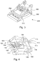
Figure 3 shows the components in a firmly locked state. The implement attachment means is provided with a number of hydraulic coupling units and electrical coupling units which shall be coupled to corresponding units provided on the implement. The coupling units are mounted on a coupling ramp on respective units. The coupling ramp on the implement attachment means is mounted so that it will be manoeuvred by the same hydraulic cylinders as those that manoeuvre the lock bolts. The rear side of the implementcoupling ramp 104 is visible inFigure 3 , whereas its front side and the coupling ramp on the implement attachment means are hidden from view. The lock bolts are thus extended at the same time as the coupling units are connected. It will be understood that the invention is not restricted to such simultaneous connection. - Neither is the invention restricted to a design in which the lock bolts are manoeuvred in the longitudinal direction of the implement attachment means as shown in
Fig. 3 . For example, the lock bolts may be arranged to be extended at right angles to said direction, i.e. in a direction parallel with thefirst gate axle 202. In such case, the bolts may be projected into openings in the side members of the implement gates. Other lock bolt manoeuvring arrangements are, of course, conceivable within the scope of the invention. - Similarly, the capturing device may have a different design to the claw-like elements, the U-profiles, on the implement attachment means and the gripping device may have a different design to the rod elements, i.e. to the gate axle, on the implement. For instance, the implement may be provided with claw-like hooks for co-action with complimentary elements on the implement attachment means, as shown in
Fig. 8 for example. - An example of the special arrangement of sensor units and detector units on which the resent invention is based will now be described more specifically with reference to
Figs 4 - 6 . -
Figure 4 is a perspective view of an implement attachment means according to the invention, although some of its components have been excluded for the sake of simplicity. These components are shown in perspective inFig. 5 . - Four
detection units 109 110 are disposed adjacent the capturing side of the implement attachment means so as to be situated in theU-profiles 104. These detection units are adapted to co-act with sensor units on thefirst gate axle 202 of the implement (seeFig. 6 ). One of these sensor units consists in thegate axle 202 itself. When the implement 200 is in the correct capture position in relation to the implement attachment means 100, as shown inFig. 2 , thefirst gate axle 202 will be located in the U-profile. Thedetection units 109 therewith indicate that the gate axle is in this position. A positive indication is triggered when the distance between thedetection units 109 and saidgate axle 202 is less than a given value, say from 2 to 5mm inclusive. This information is transferred onsignal lines 111 to the operator or to a microprocessor which automatically allows the next coupling sequence to take place. - As earlier mentioned, the next coupling sequence is to turn the implement attachment means 100 and the implement relative to one another from the position shown in
Fig. 2 to the position shown nFig. 3 . - An indication that the position shown in
Fig. 3 has been reached is achieved with the aid of a given number ofsensor units 210 disposed on the front gate axle in given angular positions around the periphery of said axle (seeFig. 6 ). In the illustrated example these are located "in the nine o'clock" position, i.e. on the inside of the gate axle on a level with its centre line. When the position shown inFig. 6 has been reached, thedetection units 110 on the implement attachment means will be located in a rotary direction opposite thesensor unit 210 on thegate axle 202 and therewith forward this information to the operator or to a microprocessor onsignal lines 112. - At this stage the system is ready to lock the implement firmly to the implement attachment means, which is effected in the manner described with reference to
Figs 1 - 3 . Thehydraulic cylinders 113 shown inFig. 5 are therewith activated, causing the cylinders to move an H-shapedyoke 107 upwards to the left inFig. 5 . Theyoke 107 carries thelock bolts 105 and thecoupling ramp 114 of the implement attachment means, which accompany the yoke as it moves. When this locking movement has terminated, thebolts 105 will protrude throughopenings 106 on the implement attachment means (seeFig. 4 ), said bolts straddling thesecond gate axle 203 of the implement together with the L-profile 103, so as to firmly lock the implement. At the same time, the coupling units on thecoupling ramp 114 of the implement attachment means have been coupled together with the coupling units on thecoupling ramp 204 of the implement (seeFig. 6 ). The system includesguides 108 for guiding movement of theyoke 107. - A
detection unit 115 is provided on theyoke 107, to indicate when this position has been reached. Asensor unit 116 is provided on a non-movable part of the implement attachment means in a position such that it will be located opposite the yoke-carrieddetection unit 115 when the correct position has been reached. Information to this effect, i.e. that locking has been completed, is then forwarded to the operator or to a microprocessor. In the case when the coupling ramps are mutually coupled at the same time as locking is achieved, as in the case of the illustrated example, this signal also constitutes information to the effect that said ramp coupling has been achieved. Otherwise, a separate pair of sensor - detection units can be provided to this end. - Should the aforedescribed sensor - detection units in either capturing position, locking position or locked position fail to forward information to the effect that respective positions have been reached, the operator is able to stop the coupling process and take necessary measures.
-
Further sensor units 217 that function to identify the implement may be provided at a suitable location, for instance on the implement coupling ramp, and that also co-act withcorresponding detection units 117 on the implement attachment means. These units may also be adapted to provide information concerning parameters related to the hydraulic and/or the electrical power transmission. - The sensor and detection units included in the system may be based on appropriate conventional technology and include contact-based magnetic, optical, electrical units or units that function in some other way.
-
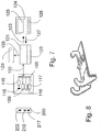
Figure 7 illustrates an example of how the information generated by the sensor and detection units can be utilised. As earlier described,sensor units respective detection units signal line bundle 120 to amicroprocessor 121 that includes aprogram 122 for processing said information. - The processed information is sent from the microprocessor to a terminal 124 in the driving cabin Of the machine via the
signal line 123. The terminal 124 includes adisplay 125 for presentation of the information concerned to the operator. Also included are a number ofcontrol buttons 126 for executing control measures initiated by the operator. These signals are transmitted from the terminal to themicroprocessor 121 via asignal line 127. - The microprocessor is connected by a
signal line 128 to acontrol unit 129 which initiates control measures on the basis of the information processed in themicroprocessor 121 and/or on the basis of measures commanded from the terminal 124. The control unit is designed to select the correct hydraulic function, pressure and fluid flow rate for respective implements and to control locking process functions, among other things. - The system described in
Fig. 7 may, of course, be expanded with further input and output functions and therewith made more sophisticated. Conversely, it may, of course, be made simpler than described. The signal lines in the system may, of course, be replaced with wireless signal transmission means.
ensuring that an implement connected to the implement attachment means will be manoeuvred in the manner intended with respect to the implement concerned
facilitate control of the work carried out with a given working implement and also of its condition.
Claims (12)
- A system comprising an implement attachment means (100) adapted to be fitted to a working machine, and further comprising at least one working implement (200), wherein the implement attachment means (100) includes first locking means (105) and first drive coupling means, wherein the implement (200) includes second locking means (203) and second drive coupling means and wherein the first and second locking means (203) are adapted for mutual co-action in releasably locking the implement (200) to the implement attachment means (100) and the first and second drive coupling means are adapted for mutual co-action in releasably connecting said drive coupling means one to the other, which system further comprises sensor means (115, 202, 210, 217) and detection means (109, 110, 116, 117) adapted for the transfer of information from the sensor means to the detection means, wherein the sensor means (115, 202, 210, 217) include at least one sensor unit mounted on either the implement attachment means or the working implement, and wherein the detection means (109, 110, 116, 117) include at least one detection unit mounted on the other of said implement attachment means or working implement, whereby at least one sensor unit (115) and at least one detection unit (116) is adapted to send information to the effect that the first (105) and the second (203) locking means are in locking engagement with one another, characterised in that at least one sensor unit (217) on the implement (200) and at least one detection unit (117) on the implement attachment means (100) is adapted to send implement identifying information.
- A system according to Claim 1, characterised in that at least one sensor unit (202, 210, 217) is mounted on the implement and at least one detection unit (109, 110, 116, 117) is mounted on the implement attachment means (100).
- A system according to Claim 1 or 2, characterised in that at least one sensor unit (202) and at least one detection unit (109) is adapted to send information to the effect that the implement attachment means (100) and the implement (102) are positioned relative to one another in a predetermined positioning area.
- A system according to Claim 3, characterised in that the implement attachment means (100) includes capturing means (104) and the implement (200) includes gripping means (202) adapted for co-action with the capturing means; in that either the capturing means (104) or the gripping means (202) include a first sensor unit (202) which is adapted to send information to a first detection unit (109) when the capturing means (104) is in engagement with the gripping means (202); and in that a second sensor unit (210) is disposed in a determined angular position on the periphery of either the capturing means or the gripping means (202) and functions to send information to a second detection unit (110) when the implement attachment means (100) and the implement (200) occupy a predetermined position of rotation relative to one another about a pivot axle defined by the capturing means or the gripping means.
- A system according to Claim 4, characterised in that the capturing means (104) includes at least one claw-like element (104) and the gripping means (202) includes at least one rod element (202) or vice versa, wherein said pivot axle is defined by the rod element (202).
- A system according to Claim 5, characterised in that said second sensor unit (210) is disposed on the rod element (202).
- A system according to any one of claims 1 - 6, characterised in that at least one sensor unit (115) and at least one detection unit (116) is adapted to send information to the effect that the first and second drive coupling means are coupled together.
- A system according to any one of claims 1 - 7, characterised in that at least one sensor unit (115) and at least one detection unit (116) is adapted to send information relating to implement working conditions.
- A system according to any one of claims 1 - 8, characterised in that the system includes control means for governing the measures or steps involved in coupling together the implement attachment means (100) and the implement (200) in response to said information, and/or for governing the measures or steps involved in manoeuvring the implement.
- A system according to any one of claims 1 - 9, characterised by a microprocessor (121) which is adapted to receive and process received information and to deliver control signals when applicable.
- A working machine equipped with the system according to any of claims 1-10.
- The use of a system according to any one of claims 1 - 11 for connecting a working implement to an implement attachment means.
Applications Claiming Priority (3)
| Application Number | Priority Date | Filing Date | Title |
|---|---|---|---|
| SE0300415A SE524941C2 (en) | 2003-02-17 | 2003-02-17 | Systems including tool brackets and work tools |
| SE0300415 | 2003-02-17 | ||
| PCT/SE2004/000199 WO2004072387A1 (en) | 2003-02-17 | 2004-02-16 | A system comprising an implement attachment means and an implement |
Publications (2)
| Publication Number | Publication Date |
|---|---|
| EP1599637A1 EP1599637A1 (en) | 2005-11-30 |
| EP1599637B1 true EP1599637B1 (en) | 2019-01-09 |
Family
ID=20290418
Family Applications (1)
| Application Number | Title | Priority Date | Filing Date |
|---|---|---|---|
| EP04711526.6A Expired - Lifetime EP1599637B1 (en) | 2003-02-17 | 2004-02-16 | A system comprising an implement attachment means and an implement |
Country Status (5)
| Country | Link |
|---|---|
| EP (1) | EP1599637B1 (en) |
| DK (1) | DK1599637T3 (en) |
| ES (1) | ES2711328T3 (en) |
| SE (1) | SE524941C2 (en) |
| WO (1) | WO2004072387A1 (en) |
Cited By (1)
| Publication number | Priority date | Publication date | Assignee | Title |
|---|---|---|---|---|
| EP4545709A1 (en) * | 2023-10-25 | 2025-04-30 | Oilquick AB | Coupling unit for machinery |
Families Citing this family (38)
| Publication number | Priority date | Publication date | Assignee | Title |
|---|---|---|---|---|
| AT9279U1 (en) * | 2006-03-23 | 2007-07-15 | Wimmer Alois Ing | TOOL DETECTION |
| AT8623U3 (en) * | 2006-03-27 | 2007-04-15 | Baumaschinentechnik Ges M B H | DEVICE FOR MOUNTING ATTACHMENTS |
| DE102006023420B4 (en) | 2006-05-17 | 2013-02-28 | Lehnhoff Hartstahl Gmbh & Co. Kg | Quick change device |
| AT505238B1 (en) * | 2007-06-13 | 2016-03-15 | Martin Holding Gmbh | CLUTCH |
| SE0801169L (en) * | 2008-05-20 | 2009-11-21 | Stig Sandberg | Arrangements for gear and attachment |
| GB2464988B8 (en) * | 2008-11-03 | 2013-02-20 | Miller Int Ltd | Coupler with coupling status sensors |
| EP2367984B1 (en) * | 2008-11-27 | 2020-06-03 | Caterpillar Work Tools B.V. | Work tool coupling arrangement |
| SE534609C2 (en) * | 2009-02-18 | 2011-10-25 | Jama Mining Machines Ab | Work platform |
| SE534020C2 (en) * | 2009-08-11 | 2011-04-05 | Oilquick Ab | Utility bracket with hydraulic controlled locking function |
| WO2011035883A1 (en) | 2009-09-22 | 2011-03-31 | Ian Hill | Hydraulic coupler with pin retention system for coupling an attachment to a work machine |
| GB2474576B (en) | 2009-10-16 | 2014-03-19 | Ian Hill | Coupler |
| GB2474572B (en) * | 2009-10-16 | 2014-11-26 | Hill Engineering Ltd | Control system for a hydraulic coupler |
| DE102010016492A1 (en) | 2010-04-16 | 2011-10-20 | Lehnhoff Hartstahl Gmbh & Co. Kg | Method for monitoring condition of tool of construction machine, particularly by coupling through quick change device, involves recognizing usage data of tool, where usage data is logged in storage device attached at side of tool |
| EP2426266B1 (en) | 2010-09-07 | 2018-10-17 | Caterpillar Work Tools B. V. | A coupling arrangement |
| EP2426267B1 (en) | 2010-09-07 | 2020-12-30 | Caterpillar Work Tools B. V. | A coupling arrangement |
| EP2426268B1 (en) * | 2010-09-07 | 2022-01-26 | Caterpillar Work Tools B. V. | A coupling arrangement |
| GB201015589D0 (en) * | 2010-09-17 | 2010-10-27 | Agco Int Gmbh | Pressurised fluid supply systems |
| SE1100099A1 (en) | 2010-11-15 | 2012-05-16 | Indexator Ab | Procedure and apparatus for a working arm |
| DE102011002712B4 (en) * | 2011-01-14 | 2018-06-21 | Alfred Ulrich | Method for controlling a mobile work machine with a tool coupling device |
| FR2988659B1 (en) * | 2012-03-28 | 2014-12-26 | Manitou Bf | DEVICE FOR DETECTING TOOL OR ACCESSORY |
| GB2509303A (en) | 2012-11-08 | 2014-07-02 | Miller Int Ltd | Coupler |
| WO2014168540A1 (en) * | 2013-04-09 | 2014-10-16 | Indexator Group Ab | System for controlling a quick coupling arranged at a tool arm |
| US20140308061A1 (en) * | 2013-04-16 | 2014-10-16 | Caterpillar Inc. | Method and System for Detecting Engagement with a Work Tool Accessory |
| ITBO20130410A1 (en) * | 2013-07-29 | 2015-01-30 | Cangini Benne Srl | CONNECTING DEVICE OF A TOOL WITH A DRIVE ARM |
| SE539425C2 (en) * | 2014-09-03 | 2017-09-19 | Ytf Sweden Ab | Quick coupler for attaching a hydraulically operated tool / implement to an excavator |
| DE102015210860A1 (en) * | 2015-06-12 | 2016-12-15 | Lehnhoff Hartstahl Gmbh & Co. Kg | Quick coupler |
| AT15844U1 (en) * | 2017-01-26 | 2018-07-15 | Baumaschinentechnik Ges M B H | Device for attaching attachments to excavator jibs |
| DE102017208935A1 (en) | 2017-05-29 | 2018-11-29 | Robert Bosch Gmbh | System and method for identifying an object |
| DE102017211237A1 (en) | 2017-07-03 | 2019-01-03 | Robert Bosch Gmbh | System and method for identifying an object |
| DE102017130436A1 (en) * | 2017-12-19 | 2019-06-19 | Oilquick Deutschland Gmbh | Adapter, quick coupler and quick-change system |
| DE102017130437A1 (en) * | 2017-12-19 | 2019-06-19 | Oilquick Deutschland Gmbh | Quick coupler, adapter and quick-change system |
| US11453993B2 (en) * | 2019-06-17 | 2022-09-27 | Caterpillar Inc. | Quick coupler with hydraulic coupling manifold |
| DE102019118913A1 (en) * | 2019-07-12 | 2021-01-14 | OilQuick Deutschland KG | Quick coupler |
| DE102020115197A1 (en) * | 2020-06-08 | 2021-12-09 | OilQuick Deutschland KG | Adapter for a quick change system and quick change system with such an adapter |
| DE102021116246A1 (en) | 2021-06-23 | 2022-12-29 | Liebherr-Hydraulikbagger Gmbh | System and method for locating an attachment |
| WO2023163673A1 (en) * | 2022-02-23 | 2023-08-31 | Inan Makina Sanayi Ve Ticaret Anonim Sirketi | Three-faceted locking mechanism |
| DE102022125112A1 (en) | 2022-09-29 | 2024-04-04 | OilQuick Deutschland KG | Quick coupler |
| FR3155547B1 (en) * | 2023-11-21 | 2026-01-30 | Ateliers De Constructions Du Beaujolais | Coupler for connecting a tool to the arm of a construction machine |
Family Cites Families (4)
| Publication number | Priority date | Publication date | Assignee | Title |
|---|---|---|---|---|
| SE467742B (en) * | 1991-09-06 | 1992-09-07 | Sonerud John Teodor | DEVICE FOR QUICK CONNECTION OF A TOOL TO AN EXCAVATOR WITH CONNECTING TO A DRIVE SYSTEM |
| US6301811B1 (en) | 2000-07-28 | 2001-10-16 | Gilmore Industries, Inc. | Coupler for a heavy-duty machine |
| US6662881B2 (en) * | 2001-06-19 | 2003-12-16 | Sweepster, Llc | Work attachment for loader vehicle having wireless control over work attachment actuator |
| DE20209518U1 (en) * | 2002-06-19 | 2003-10-30 | Liebherr-Hydraulikbagger GmbH, 88457 Kirchdorf | Construction machine with quick coupling |
-
2003
- 2003-02-17 SE SE0300415A patent/SE524941C2/en not_active IP Right Cessation
-
2004
- 2004-02-16 EP EP04711526.6A patent/EP1599637B1/en not_active Expired - Lifetime
- 2004-02-16 WO PCT/SE2004/000199 patent/WO2004072387A1/en not_active Ceased
- 2004-02-16 ES ES04711526T patent/ES2711328T3/en not_active Expired - Lifetime
- 2004-02-16 DK DK04711526.6T patent/DK1599637T3/en active
Non-Patent Citations (1)
| Title |
|---|
| None * |
Cited By (1)
| Publication number | Priority date | Publication date | Assignee | Title |
|---|---|---|---|---|
| EP4545709A1 (en) * | 2023-10-25 | 2025-04-30 | Oilquick AB | Coupling unit for machinery |
Also Published As
| Publication number | Publication date |
|---|---|
| SE0300415L (en) | 2004-08-18 |
| SE0300415D0 (en) | 2003-02-17 |
| EP1599637A1 (en) | 2005-11-30 |
| WO2004072387A1 (en) | 2004-08-26 |
| ES2711328T3 (en) | 2019-05-03 |
| SE524941C2 (en) | 2004-10-26 |
| DK1599637T3 (en) | 2019-03-18 |
Similar Documents
| Publication | Publication Date | Title |
|---|---|---|
| DK1599637T3 (en) | A SYSTEM INCLUDING A TOOL DETERMINATION MECHANISM AND A WORKING TOOL | |
| CN102224303B (en) | Coupler with coupling status sensors | |
| EP2921589B1 (en) | A working machine hitch arrangement | |
| EP2367984B1 (en) | Work tool coupling arrangement | |
| US6892822B2 (en) | Construction machine with rapid-action coupling | |
| US20090198409A1 (en) | Work tool data system | |
| US6851916B2 (en) | Coupling assembly | |
| EP2886726A1 (en) | A disarm device | |
| EP3536862B1 (en) | Quick coupling | |
| US11536009B2 (en) | System for detecting locking pin engagement of an implement | |
| US20110213534A1 (en) | Secondary drive device of a mobile working appliance | |
| EP2479349B1 (en) | Hydraulic control apparatus for work machine | |
| EP2221271B1 (en) | Work platform | |
| EP3231946B1 (en) | An apparatus comprising a coupling arrangement | |
| CN118367373A (en) | Grounding wire device and grounding wire dismounting method | |
| KR102721959B1 (en) | Sockets for power tools, methods for controlling power tools, control systems and power tools | |
| US20260098392A1 (en) | Tiltrotator arrangement including a tiltrotator and a valve arrangement | |
| EP4649204A1 (en) | A coupling system | |
| EP4400655A1 (en) | Tool holder for a machine with an improved safety system | |
| CN104314134B (en) | Engineering machinery revolution locking system and locking method |
Legal Events
| Date | Code | Title | Description |
|---|---|---|---|
| PUAI | Public reference made under article 153(3) epc to a published international application that has entered the european phase |
Free format text: ORIGINAL CODE: 0009012 |
|
| 17P | Request for examination filed |
Effective date: 20050919 |
|
| AK | Designated contracting states |
Kind code of ref document: A1 Designated state(s): AT BE BG CH CY CZ DE DK EE ES FI FR GB GR HU IE IT LI LU MC NL PT RO SE SI SK TR |
|
| AX | Request for extension of the european patent |
Extension state: AL LT LV MK |
|
| DAX | Request for extension of the european patent (deleted) | ||
| 17Q | First examination report despatched |
Effective date: 20100415 |
|
| REG | Reference to a national code |
Ref country code: DE Ref legal event code: R079 Ref document number: 602004053621 Country of ref document: DE Free format text: PREVIOUS MAIN CLASS: E02F0003360000 Ipc: E02F0009240000 |
|
| GRAP | Despatch of communication of intention to grant a patent |
Free format text: ORIGINAL CODE: EPIDOSNIGR1 |
|
| STAA | Information on the status of an ep patent application or granted ep patent |
Free format text: STATUS: GRANT OF PATENT IS INTENDED |
|
| RIC1 | Information provided on ipc code assigned before grant |
Ipc: E02F 3/36 19680901ALI20180619BHEP Ipc: E02F 9/24 19680901AFI20180619BHEP |
|
| INTG | Intention to grant announced |
Effective date: 20180718 |
|
| RIN1 | Information on inventor provided before grant (corrected) |
Inventor name: SONERUD, AKE |
|
| GRAJ | Information related to disapproval of communication of intention to grant by the applicant or resumption of examination proceedings by the epo deleted |
Free format text: ORIGINAL CODE: EPIDOSDIGR1 |
|
| STAA | Information on the status of an ep patent application or granted ep patent |
Free format text: STATUS: EXAMINATION IS IN PROGRESS |
|
| GRAS | Grant fee paid |
Free format text: ORIGINAL CODE: EPIDOSNIGR3 |
|
| STAA | Information on the status of an ep patent application or granted ep patent |
Free format text: STATUS: GRANT OF PATENT IS INTENDED |
|
| GRAP | Despatch of communication of intention to grant a patent |
Free format text: ORIGINAL CODE: EPIDOSNIGR1 |
|
| GRAA | (expected) grant |
Free format text: ORIGINAL CODE: 0009210 |
|
| STAA | Information on the status of an ep patent application or granted ep patent |
Free format text: STATUS: THE PATENT HAS BEEN GRANTED |
|
| INTC | Intention to grant announced (deleted) | ||
| INTG | Intention to grant announced |
Effective date: 20181126 |
|
| AK | Designated contracting states |
Kind code of ref document: B1 Designated state(s): AT BE BG CH CY CZ DE DK EE ES FI FR GB GR HU IE IT LI LU MC NL PT RO SE SI SK TR |
|
| REG | Reference to a national code |
Ref country code: GB Ref legal event code: FG4D |
|
| REG | Reference to a national code |
Ref country code: CH Ref legal event code: EP Ref country code: AT Ref legal event code: REF Ref document number: 1087456 Country of ref document: AT Kind code of ref document: T Effective date: 20190115 |
|
| REG | Reference to a national code |
Ref country code: DE Ref legal event code: R096 Ref document number: 602004053621 Country of ref document: DE |
|
| REG | Reference to a national code |
Ref country code: CH Ref legal event code: NV Representative=s name: FELBER UND PARTNER AG, CH Ref country code: CH Ref legal event code: PK Free format text: BERICHTIGUNGEN |
|
| REG | Reference to a national code |
Ref country code: IE Ref legal event code: FG4D |
|
| RIC2 | Information provided on ipc code assigned after grant |
Ipc: E02F 3/36 20060101ALI20180619BHEP Ipc: E02F 9/24 20060101AFI20180619BHEP |
|
| REG | Reference to a national code |
Ref country code: SE Ref legal event code: TRGR |
|
| REG | Reference to a national code |
Ref country code: DK Ref legal event code: T3 Effective date: 20190311 |
|
| REG | Reference to a national code |
Ref country code: NL Ref legal event code: FP |
|
| REG | Reference to a national code |
Ref country code: ES Ref legal event code: FG2A Ref document number: 2711328 Country of ref document: ES Kind code of ref document: T3 Effective date: 20190503 |
|
| PG25 | Lapsed in a contracting state [announced via postgrant information from national office to epo] |
Ref country code: PT Free format text: LAPSE BECAUSE OF FAILURE TO SUBMIT A TRANSLATION OF THE DESCRIPTION OR TO PAY THE FEE WITHIN THE PRESCRIBED TIME-LIMIT Effective date: 20190509 |
|
| PG25 | Lapsed in a contracting state [announced via postgrant information from national office to epo] |
Ref country code: GR Free format text: LAPSE BECAUSE OF FAILURE TO SUBMIT A TRANSLATION OF THE DESCRIPTION OR TO PAY THE FEE WITHIN THE PRESCRIBED TIME-LIMIT Effective date: 20190410 Ref country code: BG Free format text: LAPSE BECAUSE OF FAILURE TO SUBMIT A TRANSLATION OF THE DESCRIPTION OR TO PAY THE FEE WITHIN THE PRESCRIBED TIME-LIMIT Effective date: 20190409 |
|
| REG | Reference to a national code |
Ref country code: DE Ref legal event code: R097 Ref document number: 602004053621 Country of ref document: DE |
|
| PG25 | Lapsed in a contracting state [announced via postgrant information from national office to epo] |
Ref country code: MC Free format text: LAPSE BECAUSE OF FAILURE TO SUBMIT A TRANSLATION OF THE DESCRIPTION OR TO PAY THE FEE WITHIN THE PRESCRIBED TIME-LIMIT Effective date: 20190109 Ref country code: SK Free format text: LAPSE BECAUSE OF FAILURE TO SUBMIT A TRANSLATION OF THE DESCRIPTION OR TO PAY THE FEE WITHIN THE PRESCRIBED TIME-LIMIT Effective date: 20190109 Ref country code: LU Free format text: LAPSE BECAUSE OF NON-PAYMENT OF DUE FEES Effective date: 20190216 Ref country code: CZ Free format text: LAPSE BECAUSE OF FAILURE TO SUBMIT A TRANSLATION OF THE DESCRIPTION OR TO PAY THE FEE WITHIN THE PRESCRIBED TIME-LIMIT Effective date: 20190109 Ref country code: RO Free format text: LAPSE BECAUSE OF FAILURE TO SUBMIT A TRANSLATION OF THE DESCRIPTION OR TO PAY THE FEE WITHIN THE PRESCRIBED TIME-LIMIT Effective date: 20190109 Ref country code: EE Free format text: LAPSE BECAUSE OF FAILURE TO SUBMIT A TRANSLATION OF THE DESCRIPTION OR TO PAY THE FEE WITHIN THE PRESCRIBED TIME-LIMIT Effective date: 20190109 |
|
| PLBE | No opposition filed within time limit |
Free format text: ORIGINAL CODE: 0009261 |
|
| STAA | Information on the status of an ep patent application or granted ep patent |
Free format text: STATUS: NO OPPOSITION FILED WITHIN TIME LIMIT |
|
| REG | Reference to a national code |
Ref country code: IE Ref legal event code: MM4A |
|
| 26N | No opposition filed |
Effective date: 20191010 |
|
| PG25 | Lapsed in a contracting state [announced via postgrant information from national office to epo] |
Ref country code: IE Free format text: LAPSE BECAUSE OF NON-PAYMENT OF DUE FEES Effective date: 20190216 |
|
| PG25 | Lapsed in a contracting state [announced via postgrant information from national office to epo] |
Ref country code: SI Free format text: LAPSE BECAUSE OF FAILURE TO SUBMIT A TRANSLATION OF THE DESCRIPTION OR TO PAY THE FEE WITHIN THE PRESCRIBED TIME-LIMIT Effective date: 20190109 |
|
| PG25 | Lapsed in a contracting state [announced via postgrant information from national office to epo] |
Ref country code: TR Free format text: LAPSE BECAUSE OF FAILURE TO SUBMIT A TRANSLATION OF THE DESCRIPTION OR TO PAY THE FEE WITHIN THE PRESCRIBED TIME-LIMIT Effective date: 20190109 |
|
| REG | Reference to a national code |
Ref country code: AT Ref legal event code: UEP Ref document number: 1087456 Country of ref document: AT Kind code of ref document: T Effective date: 20190109 |
|
| PG25 | Lapsed in a contracting state [announced via postgrant information from national office to epo] |
Ref country code: CY Free format text: LAPSE BECAUSE OF FAILURE TO SUBMIT A TRANSLATION OF THE DESCRIPTION OR TO PAY THE FEE WITHIN THE PRESCRIBED TIME-LIMIT Effective date: 20190109 |
|
| PG25 | Lapsed in a contracting state [announced via postgrant information from national office to epo] |
Ref country code: HU Free format text: LAPSE BECAUSE OF FAILURE TO SUBMIT A TRANSLATION OF THE DESCRIPTION OR TO PAY THE FEE WITHIN THE PRESCRIBED TIME-LIMIT; INVALID AB INITIO Effective date: 20040216 |
|
| PGFP | Annual fee paid to national office [announced via postgrant information from national office to epo] |
Ref country code: NL Payment date: 20230215 Year of fee payment: 20 |
|
| PGFP | Annual fee paid to national office [announced via postgrant information from national office to epo] |
Ref country code: FR Payment date: 20230215 Year of fee payment: 20 Ref country code: FI Payment date: 20230220 Year of fee payment: 20 Ref country code: ES Payment date: 20230316 Year of fee payment: 20 Ref country code: DK Payment date: 20230215 Year of fee payment: 20 Ref country code: CH Payment date: 20230307 Year of fee payment: 20 Ref country code: AT Payment date: 20230220 Year of fee payment: 20 |
|
| PGFP | Annual fee paid to national office [announced via postgrant information from national office to epo] |
Ref country code: SE Payment date: 20230216 Year of fee payment: 20 Ref country code: IT Payment date: 20230216 Year of fee payment: 20 Ref country code: GB Payment date: 20230216 Year of fee payment: 20 Ref country code: DE Payment date: 20230217 Year of fee payment: 20 Ref country code: BE Payment date: 20230215 Year of fee payment: 20 |
|
| REG | Reference to a national code |
Ref country code: DE Ref legal event code: R071 Ref document number: 602004053621 Country of ref document: DE |
|
| REG | Reference to a national code |
Ref country code: DK Ref legal event code: EUP Expiry date: 20240216 |
|
| REG | Reference to a national code |
Ref country code: NL Ref legal event code: MK Effective date: 20240215 |
|
| REG | Reference to a national code |
Ref country code: CH Ref legal event code: PL |
|
| REG | Reference to a national code |
Ref country code: BE Ref legal event code: MK Effective date: 20240216 |
|
| REG | Reference to a national code |
Ref country code: GB Ref legal event code: PE20 Expiry date: 20240215 |
|
| REG | Reference to a national code |
Ref country code: ES Ref legal event code: FD2A Effective date: 20240405 |
|
| REG | Reference to a national code |
Ref country code: AT Ref legal event code: MK07 Ref document number: 1087456 Country of ref document: AT Kind code of ref document: T Effective date: 20240216 |
|
| PG25 | Lapsed in a contracting state [announced via postgrant information from national office to epo] |
Ref country code: ES Free format text: LAPSE BECAUSE OF EXPIRATION OF PROTECTION Effective date: 20240217 |
|
| PG25 | Lapsed in a contracting state [announced via postgrant information from national office to epo] |
Ref country code: ES Free format text: LAPSE BECAUSE OF EXPIRATION OF PROTECTION Effective date: 20240217 Ref country code: GB Free format text: LAPSE BECAUSE OF EXPIRATION OF PROTECTION Effective date: 20240215 |