EP1599279B1 - Segmented agitator reactor and method - Google Patents
Segmented agitator reactor and method Download PDFInfo
- Publication number
- EP1599279B1 EP1599279B1 EP04701302A EP04701302A EP1599279B1 EP 1599279 B1 EP1599279 B1 EP 1599279B1 EP 04701302 A EP04701302 A EP 04701302A EP 04701302 A EP04701302 A EP 04701302A EP 1599279 B1 EP1599279 B1 EP 1599279B1
- Authority
- EP
- European Patent Office
- Prior art keywords
- reactor
- blades
- agitator
- curved
- process according
- Prior art date
- Legal status (The legal status is an assumption and is not a legal conclusion. Google has not performed a legal analysis and makes no representation as to the accuracy of the status listed.)
- Expired - Lifetime
Links
- 238000000034 method Methods 0.000 title claims abstract description 23
- 230000008569 process Effects 0.000 claims abstract description 19
- 239000000126 substance Substances 0.000 claims abstract description 16
- 230000009969 flowable effect Effects 0.000 claims abstract description 4
- 230000002093 peripheral effect Effects 0.000 claims abstract 2
- 229920000642 polymer Polymers 0.000 claims description 22
- 238000006243 chemical reaction Methods 0.000 claims description 20
- 239000003054 catalyst Substances 0.000 claims description 13
- 239000007789 gas Substances 0.000 claims description 12
- 238000002156 mixing Methods 0.000 claims description 11
- 239000000178 monomer Substances 0.000 claims description 10
- 239000007788 liquid Substances 0.000 claims description 7
- 229920000098 polyolefin Polymers 0.000 claims description 7
- 239000002826 coolant Substances 0.000 claims description 6
- 239000011261 inert gas Substances 0.000 claims description 5
- 230000004888 barrier function Effects 0.000 claims description 3
- 238000004519 manufacturing process Methods 0.000 claims description 3
- IJGRMHOSHXDMSA-UHFFFAOYSA-N Atomic nitrogen Chemical compound N#N IJGRMHOSHXDMSA-UHFFFAOYSA-N 0.000 claims 2
- 238000001704 evaporation Methods 0.000 claims 1
- 229910052757 nitrogen Inorganic materials 0.000 claims 1
- 238000005201 scrubbing Methods 0.000 claims 1
- 239000002245 particle Substances 0.000 description 23
- 238000003756 stirring Methods 0.000 description 12
- QQONPFPTGQHPMA-UHFFFAOYSA-N Propene Chemical compound CC=C QQONPFPTGQHPMA-UHFFFAOYSA-N 0.000 description 9
- 125000004805 propylene group Chemical group [H]C([H])([H])C([H])([*:1])C([H])([H])[*:2] 0.000 description 8
- 125000000217 alkyl group Chemical group 0.000 description 6
- -1 polypropylene Polymers 0.000 description 6
- 239000007787 solid Substances 0.000 description 5
- 230000008901 benefit Effects 0.000 description 4
- 238000001816 cooling Methods 0.000 description 4
- 239000000203 mixture Substances 0.000 description 4
- 229920001155 polypropylene Polymers 0.000 description 4
- 239000004743 Polypropylene Substances 0.000 description 3
- SJJCABYOVIHNPZ-UHFFFAOYSA-N cyclohexyl-dimethoxy-methylsilane Chemical compound CO[Si](C)(OC)C1CCCCC1 SJJCABYOVIHNPZ-UHFFFAOYSA-N 0.000 description 3
- 238000013461 design Methods 0.000 description 3
- 238000009826 distribution Methods 0.000 description 3
- 230000000694 effects Effects 0.000 description 3
- 239000000463 material Substances 0.000 description 3
- 230000007704 transition Effects 0.000 description 3
- VOITXYVAKOUIBA-UHFFFAOYSA-N triethylaluminium Chemical compound CC[Al](CC)CC VOITXYVAKOUIBA-UHFFFAOYSA-N 0.000 description 3
- UFHFLCQGNIYNRP-UHFFFAOYSA-N Hydrogen Chemical compound [H][H] UFHFLCQGNIYNRP-UHFFFAOYSA-N 0.000 description 2
- CTQNGGLPUBDAKN-UHFFFAOYSA-N O-Xylene Chemical compound CC1=CC=CC=C1C CTQNGGLPUBDAKN-UHFFFAOYSA-N 0.000 description 2
- BLRPTPMANUNPDV-UHFFFAOYSA-N Silane Chemical compound [SiH4] BLRPTPMANUNPDV-UHFFFAOYSA-N 0.000 description 2
- 125000003118 aryl group Chemical group 0.000 description 2
- 239000003795 chemical substances by application Substances 0.000 description 2
- 238000000576 coating method Methods 0.000 description 2
- 125000000753 cycloalkyl group Chemical group 0.000 description 2
- 238000005516 engineering process Methods 0.000 description 2
- 239000012530 fluid Substances 0.000 description 2
- 238000005243 fluidization Methods 0.000 description 2
- 239000001257 hydrogen Substances 0.000 description 2
- 229910052739 hydrogen Inorganic materials 0.000 description 2
- 238000006116 polymerization reaction Methods 0.000 description 2
- 238000002360 preparation method Methods 0.000 description 2
- 238000012546 transfer Methods 0.000 description 2
- 230000009471 action Effects 0.000 description 1
- 239000012190 activator Substances 0.000 description 1
- 239000000654 additive Substances 0.000 description 1
- 239000012159 carrier gas Substances 0.000 description 1
- 238000006555 catalytic reaction Methods 0.000 description 1
- 238000001311 chemical methods and process Methods 0.000 description 1
- 238000004140 cleaning Methods 0.000 description 1
- 239000011248 coating agent Substances 0.000 description 1
- 238000010276 construction Methods 0.000 description 1
- 238000007796 conventional method Methods 0.000 description 1
- 239000000112 cooling gas Substances 0.000 description 1
- 230000007423 decrease Effects 0.000 description 1
- 238000007872 degassing Methods 0.000 description 1
- 239000000975 dye Substances 0.000 description 1
- 238000011049 filling Methods 0.000 description 1
- 238000011010 flushing procedure Methods 0.000 description 1
- 239000011521 glass Substances 0.000 description 1
- 230000005484 gravity Effects 0.000 description 1
- 238000010438 heat treatment Methods 0.000 description 1
- 239000008240 homogeneous mixture Substances 0.000 description 1
- 150000002431 hydrogen Chemical class 0.000 description 1
- 230000006872 improvement Effects 0.000 description 1
- 239000003112 inhibitor Substances 0.000 description 1
- 238000003541 multi-stage reaction Methods 0.000 description 1
- 210000000056 organ Anatomy 0.000 description 1
- 239000000843 powder Substances 0.000 description 1
- 238000004886 process control Methods 0.000 description 1
- 238000012545 processing Methods 0.000 description 1
- 238000005086 pumping Methods 0.000 description 1
- 239000002994 raw material Substances 0.000 description 1
- 239000012495 reaction gas Substances 0.000 description 1
- 239000002683 reaction inhibitor Substances 0.000 description 1
- 238000009991 scouring Methods 0.000 description 1
- 238000000926 separation method Methods 0.000 description 1
- 238000007493 shaping process Methods 0.000 description 1
- 229910000077 silane Inorganic materials 0.000 description 1
- 239000002904 solvent Substances 0.000 description 1
- 239000000725 suspension Substances 0.000 description 1
- 238000009827 uniform distribution Methods 0.000 description 1
- XLYOFNOQVPJJNP-UHFFFAOYSA-N water Substances O XLYOFNOQVPJJNP-UHFFFAOYSA-N 0.000 description 1
- 239000008096 xylene Substances 0.000 description 1
Images


Classifications
-
- B—PERFORMING OPERATIONS; TRANSPORTING
- B01—PHYSICAL OR CHEMICAL PROCESSES OR APPARATUS IN GENERAL
- B01F—MIXING, e.g. DISSOLVING, EMULSIFYING OR DISPERSING
- B01F27/00—Mixers with rotary stirring devices in fixed receptacles; Kneaders
- B01F27/05—Stirrers
- B01F27/11—Stirrers characterised by the configuration of the stirrers
- B01F27/112—Stirrers characterised by the configuration of the stirrers with arms, paddles, vanes or blades
- B01F27/1123—Stirrers characterised by the configuration of the stirrers with arms, paddles, vanes or blades sickle-shaped, i.e. curved in at least one direction
-
- B—PERFORMING OPERATIONS; TRANSPORTING
- B01—PHYSICAL OR CHEMICAL PROCESSES OR APPARATUS IN GENERAL
- B01F—MIXING, e.g. DISSOLVING, EMULSIFYING OR DISPERSING
- B01F27/00—Mixers with rotary stirring devices in fixed receptacles; Kneaders
- B01F27/50—Pipe mixers, i.e. mixers wherein the materials to be mixed flow continuously through pipes, e.g. column mixers
-
- B—PERFORMING OPERATIONS; TRANSPORTING
- B01—PHYSICAL OR CHEMICAL PROCESSES OR APPARATUS IN GENERAL
- B01F—MIXING, e.g. DISSOLVING, EMULSIFYING OR DISPERSING
- B01F27/00—Mixers with rotary stirring devices in fixed receptacles; Kneaders
- B01F27/80—Mixers with rotary stirring devices in fixed receptacles; Kneaders with stirrers rotating about a substantially vertical axis
- B01F27/90—Mixers with rotary stirring devices in fixed receptacles; Kneaders with stirrers rotating about a substantially vertical axis with paddles or arms
-
- B—PERFORMING OPERATIONS; TRANSPORTING
- B01—PHYSICAL OR CHEMICAL PROCESSES OR APPARATUS IN GENERAL
- B01F—MIXING, e.g. DISSOLVING, EMULSIFYING OR DISPERSING
- B01F35/00—Accessories for mixers; Auxiliary operations or auxiliary devices; Parts or details of general application
- B01F35/90—Heating or cooling systems
- B01F35/91—Heating or cooling systems using gas or liquid injected into the material, e.g. using liquefied carbon dioxide or steam
-
- B—PERFORMING OPERATIONS; TRANSPORTING
- B01—PHYSICAL OR CHEMICAL PROCESSES OR APPARATUS IN GENERAL
- B01J—CHEMICAL OR PHYSICAL PROCESSES, e.g. CATALYSIS OR COLLOID CHEMISTRY; THEIR RELEVANT APPARATUS
- B01J19/00—Chemical, physical or physico-chemical processes in general; Their relevant apparatus
- B01J19/0053—Details of the reactor
- B01J19/0066—Stirrers
-
- B—PERFORMING OPERATIONS; TRANSPORTING
- B01—PHYSICAL OR CHEMICAL PROCESSES OR APPARATUS IN GENERAL
- B01J—CHEMICAL OR PHYSICAL PROCESSES, e.g. CATALYSIS OR COLLOID CHEMISTRY; THEIR RELEVANT APPARATUS
- B01J19/00—Chemical, physical or physico-chemical processes in general; Their relevant apparatus
- B01J19/18—Stationary reactors having moving elements inside
- B01J19/1806—Stationary reactors having moving elements inside resulting in a turbulent flow of the reactants, such as in centrifugal-type reactors, or having a high Reynolds-number
-
- B—PERFORMING OPERATIONS; TRANSPORTING
- B01—PHYSICAL OR CHEMICAL PROCESSES OR APPARATUS IN GENERAL
- B01F—MIXING, e.g. DISSOLVING, EMULSIFYING OR DISPERSING
- B01F27/00—Mixers with rotary stirring devices in fixed receptacles; Kneaders
- B01F27/05—Stirrers
- B01F27/07—Stirrers characterised by their mounting on the shaft
- B01F27/072—Stirrers characterised by their mounting on the shaft characterised by the disposition of the stirrers with respect to the rotating axis
- B01F27/0724—Stirrers characterised by their mounting on the shaft characterised by the disposition of the stirrers with respect to the rotating axis directly mounted on the rotating axis
-
- B—PERFORMING OPERATIONS; TRANSPORTING
- B01—PHYSICAL OR CHEMICAL PROCESSES OR APPARATUS IN GENERAL
- B01F—MIXING, e.g. DISSOLVING, EMULSIFYING OR DISPERSING
- B01F27/00—Mixers with rotary stirring devices in fixed receptacles; Kneaders
- B01F27/05—Stirrers
- B01F27/11—Stirrers characterised by the configuration of the stirrers
- B01F27/19—Stirrers with two or more mixing elements mounted in sequence on the same axis
- B01F27/192—Stirrers with two or more mixing elements mounted in sequence on the same axis with dissimilar elements
-
- B—PERFORMING OPERATIONS; TRANSPORTING
- B01—PHYSICAL OR CHEMICAL PROCESSES OR APPARATUS IN GENERAL
- B01F—MIXING, e.g. DISSOLVING, EMULSIFYING OR DISPERSING
- B01F27/00—Mixers with rotary stirring devices in fixed receptacles; Kneaders
- B01F27/21—Mixers with rotary stirring devices in fixed receptacles; Kneaders characterised by their rotating shafts
- B01F27/2122—Hollow shafts
-
- B—PERFORMING OPERATIONS; TRANSPORTING
- B01—PHYSICAL OR CHEMICAL PROCESSES OR APPARATUS IN GENERAL
- B01J—CHEMICAL OR PHYSICAL PROCESSES, e.g. CATALYSIS OR COLLOID CHEMISTRY; THEIR RELEVANT APPARATUS
- B01J2219/00—Chemical, physical or physico-chemical processes in general; Their relevant apparatus
- B01J2219/00049—Controlling or regulating processes
- B01J2219/00051—Controlling the temperature
- B01J2219/00121—Controlling the temperature by direct heating or cooling
- B01J2219/00123—Controlling the temperature by direct heating or cooling adding a temperature modifying medium to the reactants
-
- B—PERFORMING OPERATIONS; TRANSPORTING
- B01—PHYSICAL OR CHEMICAL PROCESSES OR APPARATUS IN GENERAL
- B01J—CHEMICAL OR PHYSICAL PROCESSES, e.g. CATALYSIS OR COLLOID CHEMISTRY; THEIR RELEVANT APPARATUS
- B01J2219/00—Chemical, physical or physico-chemical processes in general; Their relevant apparatus
- B01J2219/00049—Controlling or regulating processes
- B01J2219/00164—Controlling or regulating processes controlling the flow
- B01J2219/00166—Controlling or regulating processes controlling the flow controlling the residence time inside the reactor vessel
-
- B—PERFORMING OPERATIONS; TRANSPORTING
- B01—PHYSICAL OR CHEMICAL PROCESSES OR APPARATUS IN GENERAL
- B01J—CHEMICAL OR PHYSICAL PROCESSES, e.g. CATALYSIS OR COLLOID CHEMISTRY; THEIR RELEVANT APPARATUS
- B01J2219/00—Chemical, physical or physico-chemical processes in general; Their relevant apparatus
- B01J2219/00761—Details of the reactor
- B01J2219/00763—Baffles
- B01J2219/00779—Baffles attached to the stirring means
-
- B—PERFORMING OPERATIONS; TRANSPORTING
- B01—PHYSICAL OR CHEMICAL PROCESSES OR APPARATUS IN GENERAL
- B01J—CHEMICAL OR PHYSICAL PROCESSES, e.g. CATALYSIS OR COLLOID CHEMISTRY; THEIR RELEVANT APPARATUS
- B01J2219/00—Chemical, physical or physico-chemical processes in general; Their relevant apparatus
- B01J2219/18—Details relating to the spatial orientation of the reactor
- B01J2219/185—Details relating to the spatial orientation of the reactor vertical
-
- B—PERFORMING OPERATIONS; TRANSPORTING
- B01—PHYSICAL OR CHEMICAL PROCESSES OR APPARATUS IN GENERAL
- B01J—CHEMICAL OR PHYSICAL PROCESSES, e.g. CATALYSIS OR COLLOID CHEMISTRY; THEIR RELEVANT APPARATUS
- B01J2219/00—Chemical, physical or physico-chemical processes in general; Their relevant apparatus
- B01J2219/19—Details relating to the geometry of the reactor
- B01J2219/194—Details relating to the geometry of the reactor round
- B01J2219/1941—Details relating to the geometry of the reactor round circular or disk-shaped
- B01J2219/1946—Details relating to the geometry of the reactor round circular or disk-shaped conical
-
- C—CHEMISTRY; METALLURGY
- C08—ORGANIC MACROMOLECULAR COMPOUNDS; THEIR PREPARATION OR CHEMICAL WORKING-UP; COMPOSITIONS BASED THEREON
- C08F—MACROMOLECULAR COMPOUNDS OBTAINED BY REACTIONS ONLY INVOLVING CARBON-TO-CARBON UNSATURATED BONDS
- C08F110/00—Homopolymers of unsaturated aliphatic hydrocarbons having only one carbon-to-carbon double bond
- C08F110/04—Monomers containing three or four carbon atoms
- C08F110/06—Propene
-
- Y—GENERAL TAGGING OF NEW TECHNOLOGICAL DEVELOPMENTS; GENERAL TAGGING OF CROSS-SECTIONAL TECHNOLOGIES SPANNING OVER SEVERAL SECTIONS OF THE IPC; TECHNICAL SUBJECTS COVERED BY FORMER USPC CROSS-REFERENCE ART COLLECTIONS [XRACs] AND DIGESTS
- Y10—TECHNICAL SUBJECTS COVERED BY FORMER USPC
- Y10S—TECHNICAL SUBJECTS COVERED BY FORMER USPC CROSS-REFERENCE ART COLLECTIONS [XRACs] AND DIGESTS
- Y10S526/00—Synthetic resins or natural rubbers -- part of the class 520 series
- Y10S526/918—Polymerization reactors for addition polymer preparation
Definitions
- the present invention relates to a device for carrying out chemical and / or physical processes, and to a process for producing polyolefins.
- Known reactors for the present purposes are basically flow tubes or stirred tanks.
- a device for homogenizing glass is known. This consists of a vertical tube with internally arranged on a shaft agitator blades. The wings are curved in opposite directions and have a constant from the shaft to the inner edge of the tube sheet width.
- US Pat. No. 4,460,278 discloses a tube reactor for the purpose of polymerization reactions, which has a plurality of upwardly and downwardly bent pairs of impeller blades with intervening disks. The purpose of this device is to create a circular flow around the ends of blade pairs.
- the present invention therefore has the object to provide a reactor for physical and / or chemical processes, which combines the advantageous characteristics of flow tube and stirred tank.
- a device for carrying out chemical and physical processes consisting of a preferably (vertical) cylindrical container with inlets and outlets, and a central shaft and arranged at this, up Radial impellers extending close to the wall.
- the stirring blades are curved in the circumferential direction. formed and combined as stirrers in pairs (one above the other) into groups, wherein the wings of the one organ of the group are radially concave and the wings of the adjacent member are radially convexly curved.
- Such a reactor according to the invention can be used in particular for producing homogeneous mixtures, for carrying out reactions between solid and / or liquid and / or gaseous substances, for heating or cooling, for coating particles and the like.
- its simple construction also allows processes under high pressure or high temperature.
- the residence time of the particles is very homogeneous when passing through the tubular reactor, also on the height of different measures, such as. B. partially cooling, addition or discharge of Substances take place, for example, can be carried out with gases, a transverse scouring when solid particles are treated in the reactor, or it can be carried out several reaction steps with different reaction components.
- Another improvement i. in particular faster mixing and narrower residence time distribution can, with a taper of the wings towards their free ends, z. B. be achieved by a trapezoidal shape of the wings, which takes into account the increase in circumferential speed in the radial direction.
- the transverse promotion can be improved by a spiral curvature of the wings, preferably in the form of a logarithmic or Archimedean spiral.
- the wings may also be employed at an angle to the longitudinal axis of the supporting shaft, in order to achieve a vertical promotion.
- the blades of the stirring element can be turned in opposite directions in such a way that they move towards one another in their area of action in order to intensify mixing.
- Solution processes have the disadvantage that the solvent used must be removed from the polymer and recovered.
- the polymer is significantly backmixed so that they can be described by a continuously operated stirred tank.
- Such backmixed processes allow only limited control of the polymer composition over the residence time of a polymer particle in the reaction zone.
- a not inconsiderable portion of the polymer particles are already removed from the reactor at an early point in the reaction, which leads to a lower catalyst utilization.
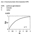
- Another important aspect is the amount of transitional material that is produced in a reactor when changing from a product A to B. This is essentially determined by the residence time behavior of the reactor system.
- Fig. 5 shows the residence time behavior of a classical CSTR.
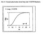
- Fig. 6 shows the residence time behavior of a loop or V-CSTR reactor.
- a system has the following features: It is a vertical, stirred reactor that is divided into segments (groups). For the reaction, it is initially irrelevant whether the main product flow is up or down.
- the reactor consists of at least 2, preferably 4, more preferably more than 12 theoretical segments, whereby the following consideration applies to the individual segment (see Fig. 7).
- the design of the segment is mainly based on the gas velocities.
- the operating point of the reactor is in the range between the gas velocity 0 and the fluidization limit preferably in the range of 0.5 to 0.8 times the gas velocity at the fluidization point.
- the residence time behavior of such a reactor system can be described by the graph (see Fig. 8) with respect to a product property F.
- Such a reactor system allows product transitions in less than a residence time.
- Each segment is equipped with a stirrer, which allows efficient horizontal mixing and thus a uniform distribution of cooling medium over the entire reaction chamber and a high relative speed ensures the particles to each other.
- Rhackorgane which can allow such a mixing behavior as stated above z. B. have the shape of a logarithmic spiral wherein the cross-sectional profile and design of the area at the Rrockerspitzen and the stirrer axis are such that the mass flow is largely ensured even in the edge zones, ie in the outermost and innermost workspace of the stirrer.
- a particular advantage is that stirrers with Archimedean or logarithmic spiral shape are self-cleaning.
- the height and diameter of the segments can be adapted to the particular kinetics of the catalyst system by selecting the reactor geometry and the arrangement and shaping of the stirring elements.
- a back-mixed zone can be provided for better mixing of the catalyst and for more effective heat removal.
- the stirrer is modified accordingly. Suitable for this purpose, for example, baffles or other internals that force mixing in the direction of the stirrer axis.
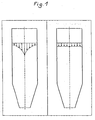
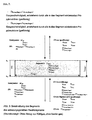
- Figure 1 shows, on the left, the flow characteristics of a fluid medium passing through a vertical cylindrical container (1) with conventional centers, vertical stirrers, mounted on a driven coaxial shaft.
- the flow rate decreases mainly due to the edge friction from the inside to the outside, so that the central particles leave the reactor much earlier than those located in the edge region, ie the residence time is very unequal.
- the right figure illustrates the effect of the procedure according to the invention.
- the flow rate of all particles is the same, they pass the reactor in a closed front as a piston flow, but with permanent mixing transverse to the reactor axis.
- the reaction rate, the heat transfer and the like it is therefore possible to define zones to which further reaction components or else reaction inhibitors can be added from the outside or via a hollow shaft.
- multistage reactions in a single reactor housing or different reaction parameters such as temperature, concentration can be carried out vary in a reactor housing.
- the conditions apply both to the preferred standing, as well as a horizontal or inclined arrangement of the reactor.
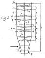
- Figure 2 illustrates the basic structure of the reactor according to the invention. It consists of a particular standing cylindrical container 1 with a central shaft 2, which may also be hollow.
- the shaft 2 carries as stirrers 5, 6, stirring blades 3, 4, which are each combined to form superimposed and interacting groups 7, wherein the wings 3, 4, are spirally curved in opposite directions, so that a stirrer 5 is a substantially radially outward directed promotion and the other 6 such causes inward.
- the distances A between the stirring elements 5, 6, are less than the distances B of the groups 7 from each other.
- the clearance A between the impellers 3, 4 and the wall of the container is matched to the particle sizes passing through the reactor, ie it can increase in the flow direction as the particle sizes increase.
- this may be conical near the bottom 8.
- a hollow shaft and corresponding outlet openings (not shown) or hollow impeller formed substances can be introduced into the process or withdrawn from this.
- FIG. 3 shows a further application of the reactor according to the invention.
- the polyolefin particles obtained by the catalytic reaction in Figure 3 and grown with the catalyst contain unreacted gaseous monomer components.
- the product is transferred (continuously) to a second reactor designed with similar impeller groups and purged with inert gas at a slight overpressure or atmospheric pressure with intensive stirring, again with the flow tube corresponding residence time ensures an absolutely uniform degassing.
- the inert gas (N 2 ) can be introduced countercurrently, for example via the bottom, or, as indicated herein, via a hollow shaft and the stirring vanes.
- additives e.g. Add dyes, which in turn are very homogeneously mixed with the polymer.
- FIG. 4 shows a top view of various embodiments of the stirring elements, wherein the wings 3, which are curved in the same direction, lie in a different plane than the oppositely curved ones 4.
- impeller pairs are used, which can also be arranged crosswise.
- the curvatures of the wings can be made stronger or weaker, and an offset arrangement of the wings within a group in the adjacent planes is also possible.
Landscapes
- Chemical & Material Sciences (AREA)
- Chemical Kinetics & Catalysis (AREA)
- Organic Chemistry (AREA)
- Polymerisation Methods In General (AREA)
- Physical Or Chemical Processes And Apparatus (AREA)
- Mixers Of The Rotary Stirring Type (AREA)
- Accessories For Mixers (AREA)
- Processing Of Solid Wastes (AREA)
- Devices And Processes Conducted In The Presence Of Fluids And Solid Particles (AREA)
- Crushing And Grinding (AREA)
Abstract
Description
Die vorliegende Erfindung betrifft eine Vorrichtung zur Durchführung von chemischen und/oder physikalischen Prozessen, sowie ein Verfahren zur Herstellung von Polyolefinen.The present invention relates to a device for carrying out chemical and / or physical processes, and to a process for producing polyolefins.
Bekannte Reaktoren für die vorliegenden Zwecke sind grundsätzlich Strömungsrohre oder Rührkessel.Known reactors for the present purposes are basically flow tubes or stirred tanks.
Aus der US-A-2,569,459 ist eine Vorrichtung zum Homogenisieren von Glas bekannt. Diese besteht aus einem senkrechten Rohr mit im Inneren an einer Welle angeordneten Rührflügeln. Die Flügel sind gegensinnig gekrümmt und weisen eine von der Welle zum Innenrand des Rohres konstante Blattbreite auf.From US-A-2,569,459 a device for homogenizing glass is known. This consists of a vertical tube with internally arranged on a shaft agitator blades. The wings are curved in opposite directions and have a constant from the shaft to the inner edge of the tube sheet width.
Aus der US-A 4,460,278 ist femer ein Rohrreaktor für die Zwecke von Polymerisationsreaktionen bekannt, der mehrere nach oben und nach unten gebogene Rührflügelpaare mit dazwischen liegendem Scheiben aufweist. Zweck dieser Vorrichtung ist die Erzeugung einer Kreisströmung um die Enden von Blattpaaren.Furthermore, US Pat. No. 4,460,278 discloses a tube reactor for the purpose of polymerization reactions, which has a plurality of upwardly and downwardly bent pairs of impeller blades with intervening disks. The purpose of this device is to create a circular flow around the ends of blade pairs.
Ideale Strömungsrohre weisen den Vorteil auf, dass sämtliche transportierten Teilchen der gleichen Verweilzeit beim Durchlauf unterliegen, im Rührkessel hingegen nicht, hier werden die Teilchen jedoch wesentlich besser gemischt. Will man daher einen hohen Mischungsgrad mit gleicher Verweilzeit aller Teilchen erreichen, so werden Rührkesselkaskaden eingesetzt. Solche Rührkesselkaskaden sind jedoch nur in separaten Behältnissen zu verwirklichen, was konstruktiven Aufwand mit sich bringt. Beide Reaktorarten weisen daher nur eingeschränkte Möglichkeiten der jeweiligen Einflussnahme auf die in ihnen behandelten fluiden Substanzteilchen oder Substanzteilchenmischungen in fester und/oder flüssiger Form auf.Ideal flow tubes have the advantage that all transported particles are subject to the same residence time in the passage, in the stirred tank, however, not, but the particles are much better mixed. If you want to achieve a high degree of mixing with the same residence time of all particles, so stirred tank cascades are used. However, such stirred tank cascades are to realize only in separate containers, which involves design effort. Both types of reactor therefore have only limited possibilities of influencing the respective fluid substance particles or substance particle mixtures in solid and / or liquid form.
Die vorliegende Erfindung hat sich daher die Aufgabe gestellt, einen Reaktor für physikalische und/oder chemische Prozesse zu schaffen, der die vorteilhaften Charakteristika von Strömungsrohr und Rührkessel vereinigt.The present invention therefore has the object to provide a reactor for physical and / or chemical processes, which combines the advantageous characteristics of flow tube and stirred tank.
Diese Aufgabe gelingt erfindungsgemäß mit einer Vorrichtung zur Durchführung von chemischen und physikalischen Prozessen gemäß Anspruch 1 bei welchen fließfähige Substanzen miteinander vermischt werden, bestehend aus einem vorzugsweise (senkrechten) zylindrischen Behälter mit Einlässen und Auslässen, sowie einer zentralen Welle und an dieser angeordneten, sich bis nahe zur Wandung erstreckenden, radialen Rührflügeln. Die Rührflügel sind in Umfangsrichtung gesehen gekrümmt. ausgebildet und als Rührorgane paarweise (übereinander) zu Gruppen zusammengefasst, wobei die Flügel des einen Organs der Gruppe radial konkav und die Flügel des benachbarten Organs radial konvex gekrümmt sind.This object is achieved according to the invention with a device for carrying out chemical and physical processes according to
Die Besonderheit einer solchen Lösung besteht in folgendem: Die den rohrFörmigen Reaktor durchwandernden festen oder flüssigen Partikel oder Gase werden von den in Drehrichtung gesehen konkaven Rührflügeln vom vertikalen Mittenbereich nach außen zur Rohrwandung verdrängt, wohingegen die darüber- oder darunterliegenden gegensinnig geformten Flügel der jeweiligen baulichen Gruppe diese wieder nach innen fördern. Gleichzeitig entstehen an den Kanten der Flügel umgelenkte Strömungsfäden, so dass insgesamt die Teilchen die Bewegung einer geschlossenen Spirale durchlaufen. Wird ein solcher Reaktor nicht statisch betrieben, sondern ein vertikaler Durchsatz, z.B. durch Pumpen oder unter Schwerkraft erzeugt, so ergibt sich neben einer sehr guten Vermischung auch der Vorteil einer ausgesprochen homogenen Verweilzeitverteilung. Damit verbunden ist natürlich auch eine gegenüber herkömmlichen Reaktoren wesentlich verringerte Baugröße.The peculiarity of such a solution consists in the following: The solid or liquid particles or gases passing through the tubular reactor are displaced outwardly from the vertical center region towards the pipe wall by the concave impellers, whereas the opposite or underlying oppositely shaped vanes of the respective structural group promote them back inside. At the same time, deflected flow threads are formed at the edges of the wings, so that overall the particles undergo the movement of a closed spiral. If such a reactor is not operated statically, but a vertical throughput, e.g. produced by pumping or by gravity, so in addition to a very good mixing and the advantage of a very homogeneous residence time distribution results. This is of course associated with a significantly reduced compared to conventional reactors size.
Ein solcher erfindungsgemäßer Reaktor kann insbesondere zur Herstellung homogener Mischungen, zur Durchführung von Reaktionen zwischen festen und/oder flüssigen und/oder gasförmigen Substanzen, zum Erwärmen oder Kühlen, zum Beschichten von Teilchen und dergleichen verwendet werden. Sein einfacher Aufbau erlaubt selbstverständlich auch Prozesse unter hohem Druck oder hoher Temperatur.Such a reactor according to the invention can be used in particular for producing homogeneous mixtures, for carrying out reactions between solid and / or liquid and / or gaseous substances, for heating or cooling, for coating particles and the like. Of course, its simple construction also allows processes under high pressure or high temperature.
Ein weiterer ganz besonderer Vorteil liegt in der Möglichkeit einer sehr genauen Prozessbeeinflussung.Another very special advantage is the possibility of very precise process control.
Da, wie oben gesagt, die Verweilzeit der Teilchen beim Durchgang durch den rohrförmigen Reaktor sehr homogen ist, können auch über die Höhe unterschiedliche Maßnahmen, wie z. B. bereichsweise Kühlung, Zugabe oder Abführung von Stoffen erfolgen, beispielsweise kann mit Gasen eine Querspülung erfolgen, wenn Feststoffteilchen im Reaktor behandelt werden, oder aber es können mehrere Reaktionsschritte mit unterschiedlichen Reaktionskomponenten vorgenommen werden.Since, as stated above, the residence time of the particles is very homogeneous when passing through the tubular reactor, also on the height of different measures, such as. B. partially cooling, addition or discharge of Substances take place, for example, can be carried out with gases, a transverse scouring when solid particles are treated in the reactor, or it can be carried out several reaction steps with different reaction components.
Eine weitere Verbesserung, d.h. insbesondere schnellere Vermischung und engere Verweilzeitverteilung kann bei einer Verjüngung der Flügel zu ihren freien Enden hin, z. B. durch eine trapezförmige Form der Flügel erreicht werden, was die Zunahme der Umfangsgeschwindigkeit in radialer Richtung berücksichtigt.Another improvement, i. in particular faster mixing and narrower residence time distribution can, with a taper of the wings towards their free ends, z. B. be achieved by a trapezoidal shape of the wings, which takes into account the increase in circumferential speed in the radial direction.
Ebenso kann die Querförderung durch eine spiralförmige Krümmung der Flügel verbessert werden, vorzugsweise in Form einer logarithmischen oder archimedischen Spirale.Likewise, the transverse promotion can be improved by a spiral curvature of the wings, preferably in the form of a logarithmic or Archimedean spiral.
Darüber hinaus können die Flügel auch unter einem Winkel zur Längsachse der diese tragenden Welle angestellt sein, um eine vertikale Förderung zu erreichen. Beispielsweise können die Flügel des Rührorgans gegensinnig derart angestellt sein, dass sie die Substanz in ihrem Wirkungsbereich aufeinander zubewegen, um eine Vermischung zu intensivieren.In addition, the wings may also be employed at an angle to the longitudinal axis of the supporting shaft, in order to achieve a vertical promotion. For example, the blades of the stirring element can be turned in opposite directions in such a way that they move towards one another in their area of action in order to intensify mixing.
Eine weitere Möglichkeit der Einflussnahme auf die Komponenten des Reaktorinhalts kann erhalten werden, wenn zwischen den einzelnen Rührorganen, d. h. jeweils zwischen den Rührerpaaren Sperrscheiben angeordnet sind, die beim Durchlauf Substanz nach außen zur Rohrwandung führen bzw. Turbulenz glätten.Another possibility of influencing the components of the reactor contents can be obtained if between the individual stirring elements, i. H. In each case between the pairs of stirrer locking discs are arranged, which lead substance in the passage to the outside of the pipe wall or smooth turbulence.
In besonders vorteilhafter Weise lässt sich mit einem solchen Reaktor die Herstellung von Polyolefinen verwirklichen.In a particularly advantageous manner can be realized with such a reactor, the production of polyolefins.
Dabei wird von dem Effekt Gebrauch gemacht, dass die Wirkung der Rührflügelgruppen einem verbesserten Rührkessel gleichkommt, es fehlen Totzonen und es liegt eine sehr hohe Relativgeschwindigkeit der Reaktionskomponenten Monomeres, Polymeres und Katalysator vor, so dass alle die erstere(n) Gruppe(n) verlassenden Produkte, gleich weit reagiert haben, insbesondere ergibt sich dabei auch eine gegenüber dem Stand der Technik homogenere Temperaturverteilung.It is made use of the effect that the effect of the impeller groups is equivalent to an improved stirred tank, dead zones are missing and it is a very high relative velocity of the reaction components of monomer, polymer and catalyst, so that all the former (s) group (s) leaving products have reacted the same, in particular, this results in a relation to the prior art more homogeneous temperature distribution.
Gängige Verfahren zur Herstellung von Polyolefinen, insbesondere Polypropylen sind in der zugänglichen Literatur ausführlich beschrieben.
Wirbelschichtreaktoren, z. B.:
- US 4,003,712 der Union Carbide Corp.,
- EP 1080782 der Sumitomo Chem. Corp. LTD
- WO 97/36942 der Dow chem. Corp.
- WO 97/04015 der Montell Technology CO BV (Basell)
- US 4,921,919 der Standard Oil CO
- US 3,639,377 der BASF AG
Fluidized bed reactors, z. B .:
- US 4,003,712 of Union Carbide Corp.,
- EP 1080782 of Sumitomo Chem. Corp. LTD
- WO 97/36942 the Dow chem. Corp.
- WO 97/04015 of Montell Technology CO BV (Basell)
- US 4,921,919 the Standard Oil CO
- US Pat. No. 3,639,377 to BASF AG
Mischorgane für Reaktoren sind z. B. in DE 1,218,265 oder WO99/29406 beschrieben.Mixing devices for reactors are z. In DE 1,218,265 or WO99 / 29406.
Sämtliche aufgeführten Verfahren haben zum Ziel, die Reaktionswärme schnell und gleichmäßig abzuführen. In Wirbelschichtreaktoren wird dies durch vergleichsweise große Gasmengen und hohe Relativgeschwindigkeit der Partikel zueinander bewerkstelligt. Nachteil dieser Verfahren ist wie bereits erwähnt die hohe Gasmenge. Üblicherweise wird hierzu dem Reaktionsgas ein signifikanter Anteil von Trägergas zugemischt, welches anschließend wieder zurückgewonnen werden muss. Außerdem sind die Vorrichtungen zur Erzeugung der notwendigen hohen Gasgeschwindigkeiten relativ teuer und die Reaktoren neigen zur Bildung von Polymerbelägen.All the processes listed have the aim of dissipating the heat of reaction quickly and uniformly. In fluidized bed reactors this is accomplished by comparatively large amounts of gas and high relative velocity of the particles to each other. Disadvantage of this method is, as already mentioned, the high amount of gas. Usually this is the reaction gas, a significant proportion of carrier gas added, which then has to be recovered again. In addition, the devices for generating the necessary high gas velocities are relatively expensive and the reactors tend to form polymer coatings.
Lösungsprozesse haben den Nachteil, dass das verwendete Lösungsmittel aus dem Polymeren entfernt werden und zurückgewonnen werden muss. In sämtlichen beschriebenen Prozessen wird das Polymer signifikant rückvermischt so dass diese durch einen kontinuierlich betriebenen Rührkessel beschrieben werden können. Solcherart rückvermischte Prozesse erlauben nur eingeschränkte Kontrolle der Polymerzusammensetzung über die Verweilzeit eines Polymerteilchens in der Reaktionszone. Weiterhin wird bei solchen Prozessen ein nicht unerheblicher Teil der Polymerteilchen zu einem frühen Zeitpunkt der Reaktion bereits wieder aus dem Reaktor entfernt, was zu einer geringeren Katalysatorausnutzung führt.Solution processes have the disadvantage that the solvent used must be removed from the polymer and recovered. In all of the processes described, the polymer is significantly backmixed so that they can be described by a continuously operated stirred tank. Such backmixed processes allow only limited control of the polymer composition over the residence time of a polymer particle in the reaction zone. Furthermore, in such processes, a not inconsiderable portion of the polymer particles are already removed from the reactor at an early point in the reaction, which leads to a lower catalyst utilization.
Diese Aufgabe wird durch ein Verfahren gemäß Anspruch 8 gelöst.This object is achieved by a method according to
Ein weiterer wesentlicher Aspekt ist die Menge an Übergangsmaterial, die in einem Reaktor beim Wechsel von einem Produkt A nach B anfällt. Diese ist im Wesentlichen durch das Verweilzeitverhalten des Reaktorsystems bestimmt.Another important aspect is the amount of transitional material that is produced in a reactor when changing from a product A to B. This is essentially determined by the residence time behavior of the reactor system.
Die Abb. 5 zeigt das Verweilzeitverhalten eines klassischen CSTR.Fig. 5 shows the residence time behavior of a classical CSTR.
Wie in Abb. 5 zu sehen ist, benötigt man für einen Produktübergang einer Materialeigenschaft F in einem CSTR ca. 3 Verweilzeiten. Unterschiedlich gestaltet sich dies bei Reaktoren, die zumindest teilweise das Verhältnis einer Kaskade aufweisen wie z. B. loop Reaktoren oder liegende (vertikale) Reaktoren.As can be seen in Fig. 5, it takes about 3 residence times for a product transfer of a material property F in a CSTR. This is different in reactors, which at least partially have the ratio of a cascade such. B. loop reactors or horizontal (vertical) reactors.
Die Abb. 6 zeigt das Verweilzeitverhalten eines loop oder V-CSTR-Reaktors.Fig. 6 shows the residence time behavior of a loop or V-CSTR reactor.
Wie in Abb. 6 zu sehen, kann der Produktübergang hinsichtlich einer Materialeigenschaft F bei loop bzw. V-CSTR Reaktoren theoretisch mit einer Kaskade von n = 4 CSTR beschrieben werden. Nachteilig ist, dass weiterhin etwa 2 Verweitzeiten über die gesamte Kaskade für einen Produktübergang benötigt werden.As can be seen in Fig. 6, the product transition with respect to a material property F for loop or V-CSTR reactors can theoretically be described with a cascade of n = 4 CSTR. The disadvantage is that further about 2 Verweitzeiten over the entire cascade needed for a product transition.
Der erfindungsgemäße Reaktor genügt folgenden Anforderungen:
- Hohe Relativgeschwindigkeit der Polymerpartikel zueinander.
- Hohe Relativgeschwindigkeit der Polymerpartikel quer zur Reaktorachse
- Geschwindigkeit der Polymerpartikel in Reaktorachse proportional zur Volumenexpansion der Polymerpartikel während der Reaktion mit minimaler Rückvermischung.
- High relative velocity of the polymer particles to each other.
- High relative velocity of the polymer particles transverse to the reactor axis
- Speed of the polymer particles in the reactor axis proportional to the volume expansion of the polymer particles during the reaction with minimal backmixing.
Gemäß dem vorstehenden Leistungsprofil wurde ein System entwickelt, das die folgenden Merkmale aufweist: Es handelt sich um einen vertikalen, gerührten Reaktor, der in Segmente (Gruppen) aufgeteilt ist. Für die Reaktionsführung ist es zunächst unerheblich ob der Haupt-Produktfluss nach oben oder nach unten erfolgt. Der Reaktor besteht aus mindestens jedoch 2 bevorzugt 4, besonders bevorzugt mehr als 12 theoretischen Segmenten wobei für das einzelne Segment folgende Betrachtung gilt (s. Abb. 7).In accordance with the above performance profile, a system has been developed that has the following features: It is a vertical, stirred reactor that is divided into segments (groups). For the reaction, it is initially irrelevant whether the main product flow is up or down. The reactor consists of at least 2, preferably 4, more preferably more than 12 theoretical segments, whereby the following consideration applies to the individual segment (see Fig. 7).
Die Gestaltung des Segments orientiert sich hauptsächlich an den Gasgeschwindigkeiten. Der Betriebspunkt des Reaktors liegt im Bereich zwischen der Gasgeschwindigkeit 0 und der Fluidierungsgrenze vorzugsweise im Bereich des 0.5 - 0.8 fachen der Gasgeschwindigkeit am Fluidisierungspunkt.The design of the segment is mainly based on the gas velocities. The operating point of the reactor is in the range between the
Das Verweilzeitverhalten eines solchen Reaktorsystems kann mit der Graphik (s. Abb. 8) hinsichtlich einer Produkteigenschaft F beschrieben werden.The residence time behavior of such a reactor system can be described by the graph (see Fig. 8) with respect to a product property F.
Ein so geartetes Reaktorsystem ermöglicht Produktübergänge in weniger als einer Verweilzeit.Such a reactor system allows product transitions in less than a residence time.
Jedes Segment ist mit einem Rührorgan ausgestattet, das eine effiziente horizontale Durchmischung ermöglicht und damit eine gleichmäßige Verteilung von Kühlmedium über den gesamten Reaktionsraum sowie eine hohe Relativgeschwindigkeit der Partikel zueinander gewährleistet. Rührorgane die ein solches Mischverhalten ermöglichen können wie oben gesagt z. B. die Form einer logarithmischen Spirale aufweisen wobei Querschnittsprofil und Ausgestaltung des Bereichs an den Rührerspitzen und der Rührerachse solcherart sind, dass der Massefluss auch in den Randzonen, d. h. im äußersten und innersten Arbeitsbereich des Rührers weitgehend gewährleistet bleibt. Ein besonderer Vorteil ist dabei, dass Rührer mit archimedischer oder logarithmischer Spiralform selbstreinigend sind.Each segment is equipped with a stirrer, which allows efficient horizontal mixing and thus a uniform distribution of cooling medium over the entire reaction chamber and a high relative speed ensures the particles to each other. Rührorgane which can allow such a mixing behavior as stated above z. B. have the shape of a logarithmic spiral wherein the cross-sectional profile and design of the area at the Rührerspitzen and the stirrer axis are such that the mass flow is largely ensured even in the edge zones, ie in the outermost and innermost workspace of the stirrer. A particular advantage is that stirrers with Archimedean or logarithmic spiral shape are self-cleaning.
Höhe und Durchmesser der Segmente können durch Wahl der Reaktorgeometrie und der Anordnung und Formgebung der Rührorgane an die jeweilige Kinetik des Katalysatorsystems angepasst werden.The height and diameter of the segments can be adapted to the particular kinetics of the catalyst system by selecting the reactor geometry and the arrangement and shaping of the stirring elements.
Im Bereich der Einspülung des Katalysatorsystems kann zur besseren Einmischung des Katalysators und zur effektiveren Wärmeabfuhr eine rückvermischte Zone vorgesehen werden. In diesem Falle wird das Rührorgan entsprechend modifiziert. Geeignet sind zu diesem Zweck zum Beispiel Stromstörer oder andere Einbauten, die eine Vermischung in Richtung der Rührerachse erzwingen.In the field of flushing of the catalyst system, a back-mixed zone can be provided for better mixing of the catalyst and for more effective heat removal. In this case, the stirrer is modified accordingly. Suitable for this purpose, for example, baffles or other internals that force mixing in the direction of the stirrer axis.
Als Kühlmedium zur Abführung der Reaktionswärme wird vorzugsweise flüssiges Monomer verwendet. Sofern sinnvoll können auch inerte Komponenten, die nicht am Reaktionsgeschehen teilnehmen eingesetzt werden. Im einfachsten Fall wird das Kühlmedium von unten in den Reaktor dosiert und oben abgezogen, unabhängig von der Hauptflussrichtung des Produktes. Es können ebenfalls einzelne Segmente mit separaten Dosierstellen für Kühlmedium und/oder weitere Reaktionskomponenten wie Monomere, Katalysatoren, Aktivatoren, Inhibitoren etc. versehen werden. Weiterhin besteht die Möglichkeit, durch Abzug von Kühlmedium oder Reaktionskomponenten innerhalb der Segmente die Gaszusammensetzung zu beeinflussen. Gleiches gilt für den Einsatz von Sperrmedien zwischen Segmenten zur Trennung von Gaszusammensetzungen innerhalb des Reaktors. Anhand der beiliegenden Figuren wird die vorliegende Erfindung näher erläutert. Dabei zeigen:
-
Figur 1 das Fließverhalten im Vergleich zum Stand der Technik, -
Figur 2 den prinzipiellen Aufbau des erfindungsgemäßen Reaktors und -
Figur 3 die Spülung eines Polyolefins mit Inertgas -
Figur 4 Rührorgane
- FIG. 1 shows the flow behavior in comparison with the prior art,
- Figure 2 shows the basic structure of the reactor according to the invention and
- Figure 3, the rinsing of a polyolefin with inert gas
- FIG. 4 stirring elements
Figur 1 zeigt links die Strömungscharakteristik eines fluiden Mediums beim Durchgang durch einen stehenden zylindrischen Behälter (1) mit herkömmlichen Zentralen, vertikalen Rührorganen, die auf einer angetriebenen koaxialen Welle angeordnet sind. Die Strömungsgeschwindigkeit nimmt hauptsächlich infolge der Randreibung von innen nach außen ab, so dass die zentralen Teilchen den Reaktor deutlich früher verlassen, als die im Randbereich befindlichen, d. h. die Verweilzeit ist sehr ungleich. Figure 1 shows, on the left, the flow characteristics of a fluid medium passing through a vertical cylindrical container (1) with conventional centers, vertical stirrers, mounted on a driven coaxial shaft. The flow rate decreases mainly due to the edge friction from the inside to the outside, so that the central particles leave the reactor much earlier than those located in the edge region, ie the residence time is very unequal.
Die rechte Abbildung veranschaulicht den Effekt des erfindungsgemäßen Vorgehens. Die Strömungsgeschwindigkeit aller Teilchen ist gleich, sie passieren den Reaktor in geschlossener Front als Kolbenströmung, jedoch unter permanenter Vermischung quer zur Reaktorachse. Unter Berücksichtigung der Reaktionsgeschwindigkeit, des Wärmeübergangs und dergleichen lassen sich daher Zonen definieren, denen von außen oder über eine Hohlwelle weitere Reaktionskomponenten oder auch Reaktionshemmer zugegeben werden können, beispielsweise lassen sich so mehrstufige Reaktionen in einem einzigen Reaktorgehäuse durchführen oder auch unterschiedliche Reaktionsparameter wie Temperatur, Konzentration in einem Reaktorgehäuse variieren.The right figure illustrates the effect of the procedure according to the invention. The flow rate of all particles is the same, they pass the reactor in a closed front as a piston flow, but with permanent mixing transverse to the reactor axis. Taking into account the reaction rate, the heat transfer and the like, it is therefore possible to define zones to which further reaction components or else reaction inhibitors can be added from the outside or via a hollow shaft. For example, multistage reactions in a single reactor housing or different reaction parameters such as temperature, concentration can be carried out vary in a reactor housing.
Die Verhältnisse gelten sowohl für die bevorzugte stehende, als auch eine liegende oder geneigte Anordnung des Reaktors.The conditions apply both to the preferred standing, as well as a horizontal or inclined arrangement of the reactor.
Figur 2 veranschaulicht den prinzipiellen Aufbau des erfindungsgemäßen Reaktors.
Er besteht aus einem insbesondere stehenden zylindrischen Behälter 1 mit einer mittigen Welle 2, die auch hohl ausgebildet sein kann. Die Welle 2 trägt als Rührorgane 5, 6, Rührflügel 3, 4, welche jeweils zu übereinanderliegenden und miteinander wirkenden Gruppen 7 zusammengefasst sind, wobei die Flügel 3, 4, gegensinnig spiralig gekrümmt sind, so dass ein Rührorgan 5 eine im wesentlichen radial nach außen gerichtete Förderung und das andere 6 eine solche nach innen gerichtet bewirkt. Vorteilhafterweise sind dabei die Abstände A zwischen den Rührorganen 5, 6, geringer, als die Abstände B der Gruppen 7 voneinander. Das Spiel A zwischen den Rührflügeln 3, 4 und der Wandung des Behälters ist auf die den Reaktor durchwandernden Teilchengrößen abgestimmt, d. h. es kann bei anwachsenden Teilchengrößen in Strömungsrichtung zunehmen. Figure 2 illustrates the basic structure of the reactor according to the invention.
It consists of a particular standing
Um die Strömungsgeschwindigkeit am Auslauf des Reaktors zu erhöhen, kann dieser nahe dem Boden 8 konisch ausgebildet sein. Über eine Hohlwelle und entsprechende Austrittsöffnungen (nicht gezeigt) bzw. hohl ausgebildete Rührflügel können in den Prozess Substanzen eingeschleust oder auch aus diesem abgezogen werden.In order to increase the flow velocity at the outlet of the reactor, this may be conical near the
Figur 3 zeigt eine weitere Anwendung des erfindungsgemäßen Reaktors. FIG. 3 shows a further application of the reactor according to the invention.
Die durch die katalytische Reaktion in Figur 3 erhaltenen und mit dem Katalysator angewachsenen Polyolefinteilchen enthalten unreagierte Bestandteile an gasförmigem Monomer.The polyolefin particles obtained by the catalytic reaction in Figure 3 and grown with the catalyst contain unreacted gaseous monomer components.
Dieses ist vor der Weiterverarbeitung zu entfernen. Dazu wird das Produkt (kontinuierlich) in einen zweiten, mit ähnlichen Rührflügelgruppen ausgestalteten Reaktor überführt und mit Inertgas bei leichtem Überdruck oder auch Atmosphärendruck unter intensivem Rühren gespült, wobei wiederum das dem Strömungsrohr entsprechenden Verweilzeitverhalten für eine absolut gleichmäßige Entgasung sorgt.This must be removed before further processing. For this purpose, the product is transferred (continuously) to a second reactor designed with similar impeller groups and purged with inert gas at a slight overpressure or atmospheric pressure with intensive stirring, again with the flow tube corresponding residence time ensures an absolutely uniform degassing.
Das Inertgas (N2) kann im Gegenstrom z.B. über den Boden eingeleitet werden, oder aber, wie vorliegend angedeutet über eine Hohlwelle und die Rührflügel.The inert gas (N 2 ) can be introduced countercurrently, for example via the bottom, or, as indicated herein, via a hollow shaft and the stirring vanes.
Grundsätzlich ist es dabei oder auch anschließend möglich, dem Polymer Additive z.B. Farbstoffe zuzugeben, die wiederum sehr homogen mit dem Polymer vermischt werden.Basically, it is possible or subsequently possible to add additives to the polymer, e.g. Add dyes, which in turn are very homogeneously mixed with the polymer.
Figur 4 zeigt in der Draufsicht verschiedene Ausführungen der Rührorgane, wobei die gleichsinnig gekrümmtem Flügel 3 in einer anderen Ebene liegen, als die entgegengesetzt gekrümmten 4.FIG. 4 shows a top view of various embodiments of the stirring elements, wherein the
Vorzugsweise werden Rührflügelpaare eingesetzt, die auch kreuzweise angeordnet sein können. Je nach Rotationsgeschwindigkeit können die Krümmungen der Flügel stärker oder schwächer ausgeführt sein und eine zueinander versetzte Anordnung der Flügel innerhalb einer Gruppe in den benachbarten Ebenen ist ebenfalls möglich.Preferably, impeller pairs are used, which can also be arranged crosswise. Depending on the rotational speed, the curvatures of the wings can be made stronger or weaker, and an offset arrangement of the wings within a group in the adjacent planes is also possible.
Das nachstehende Ausführungsbeispiel beschreibt die Herstellung von Polypropylen in einem Reaktor, z. B. gemäß Figur 2.The following example describes the preparation of polypropylene in a reactor, e.g. B. according to FIG. 2
Die eingesetzten Rohstoffe sind die folgenden:
- Propylen: Vorzugsweise Polymergrade mit einer Reinheit von > 99,8 %
- Katalysator:
Ziegler Katalysator der 4. Generation oder andere zur Herstellung von Polypropylen geeigneten Katalysatoren - Alkyl: vorzugsweise Triethylaluminium
- Donor: Vorzugsweise ein Silan der Gruppe Dialkyldialkoxysilan der allgemeinen Formel RR'Si(OMe)2 mit R, R' gleich oder verschieden, R, R' = Alkyl, Isoalkyl, Aryl, Cycloalkyl...Im vorliegenden Beispiel wurde Cyclohexyl-methyl-dimethoxysilan verwendet.
- Wasserstoff: Reinst.
- Propylene: preferably polymer grades with a purity of> 99.8%
- Catalyst: Ziegler 4th generation catalyst or other catalysts suitable for the production of polypropylene
- Alkyl: preferably triethylaluminum
- Donor: preferably a silane of the group dialkyldialkoxysilane of the general formula RR'Si (OMe) 2 where R, R 'are identical or different, R, R' = alkyl, isoalkyl, aryl, cycloalkyl ... In the present example, cyclohexylmethyl- dimethoxysilane used.
- Hydrogen: pure.
In einen mit Polymerpulver einer mittleren Schüttdichte von 400 kg/m3 gefüllten, kontinuierlich betriebenen Reaktor (top down) mit einer Länge von 16,3 m und einem Anfangsdurchmesser D2 von 1,74 m sowie einem Enddurchmesser von 0,7 m und einem Nutzvolumen von 12 m3 wird der Katalysator kontinuierlich von oben auf das Rührbett dosiert. Der Katalysator ist in Propylen aufsuspendiert und wird als Suspension mit einer Konzentration von 10 % mittels Reinpropylen in einer Menge von 1 t/h in den Reaktor verbracht. Die Rührgeschwindigkeit beträgt 24 U/min. Gleichfalls von oben werden Triethylaluminium (Alkyl) in einer Menge von 250 g/t gesamt Frischpropylendosierung sowie Cyclohexylmethyldimethoxysilan (Donor) in einer Menge von 21 g/t gesamt Frischpropylendosierung eindosiert, so dass sich ein molares Verhältnis von Alkyl/Donor 20/1 einstellt. Weiteres Propylen wird entsprechend dem Verbrauch durch die Polymerisation druckgeregelt von unten in den Reaktor eingespeist. Der Reaktordruck wird durch diesen geregelten Monomerstrom bei 30 bar gehalten. Die Temperaturregelung erfolgt in der Art, dass pro Gruppe (Rührerpaar), z.B. seitlich entsprechend der gemessenen Temperatur flüssiges Propylen zur Kühlung eingespeist wird. Das gesamte zur Kühlung eingesetzte Propylen wird über den Reaktordeckel in einen Kühler verbracht, wo es kondensiert und mittels einer Pumpe wieder zu den einzelnen Dosierstellen verbracht wird. In den untersten Strom des Kühlgases wird Wasser stoff in einer Menge von 62 g/t eingesetztes Frischpropylen zudosiert. Wasserstoff dient als Regler für das Polymermolekulargewicht. Gleichfalls wird unten Frischpropylen in einer Menge von 5.1 t/h eindosiert. Der Abzug des gebildeten Polymeren erfolgt kontinuierlich über eine geeignete Austragsarmatur in der Art, dass der Füllstand des Reaktors konstant bleibt. Zur Messung des Füllstandes können übliche Methoden zur Füllsfiandmessung von Schüttgütern angewendet werden. Die mittlere Menge an ausgetragenem Polymer beträgt 4,8 t/h, entsprechend einer mittleren Verweilzeit des Polymeren von 1 h, das erhaltene Polymer hat die folgenden Eigenschaften:
- MFI (Melt flow index): 12 g /10 min. (nach ASTM D 1238)
- XL (Xylol löslicher Anteil): 2,2 % (nach ASTM D 5492)
- Mittlere Schüttdichte: 440 g/l. (nach ASTM D 1895)
- MFI (melt flow index): 12 g / 10 min. (according to ASTM D 1238)
- XL (xylene soluble fraction): 2.2% (according to ASTM D 5492)
- Average Bulk Density: 440 g / l. (according to ASTM D 1895)
Claims (13)
- Apparatus for performing chemical and physical processes, wherein flowable substances are mixed together, comprising a preferably (vertical) cylindrical vessel (1) with inlets and outlets, as well as a central shaft (2) and radial agitator blades (3; 4) arranged on the said shaft, extending close to the wall, characterised by the following features:a) the agitator blades (3; 4) are designed in a curved manner when viewed in the peripheral direction andb) are combined in pairs of agitator elements (5; 6), positioned one above the other, to form groups (7),c) the blades (3) of one element (5) of the group (7) being curved in a radially concave manner and the blades (4) of the other element (6) being curved in a radially convex manner characterised in thatd) the blades (3; 4) are tapered towards their free ends.
- Apparatus according to claim 1 or 2, characterised in that the curvature of the blades (3; 4) is spiral-shaped.
- Apparatus according to claim 1 or 2, characterised in that the curvature is logarithmic or Archimedean.
- Apparatus according to any one of claims 1 to 3, characterised in that the blades (3; 4) are pitched in the axial direction for vertical feeding of substances in the axial direction.
- Apparatus according to claim 4, characterised in that the blades (3; 4) of the agitator elements have pitching angles in opposite directions.
- Apparatus according to any one of claims 1 to 5, characterised in that barrier elements are provided between the groups of agitator elements.
- Apparatus according to any one of claims 1 to 6, characterised in that in the vessel wall spaced apart inlets and outlets are provided for feeding reaction components and/or coolants to the flowable substances.
- Process for preparing polymers in a tubular reactor, the reaction components being moved through the reactor in an axial direction and in the course thereof being conveyed alternatingly towards and away from the reactor axis by pairs of agitator blades, curved in opposite directions, combined to form groups one above the other, substantially normal to the reactor axis, thereby intensely mixing the reaction components, characterised in that the blades are being tapered towards their ends.
- Process according to claim 8, characterised in that an olefin polymer is placed into the reactor and a monomer and a catalyst system are added to the latter.
- Process according to claim 9, characterised in that the reactor content is cooled by adding a liquid monomer, the monomer evaporating in the course thereof and being withdrawn as a gaseous substance.
- Process according to any one of claims 8 to 10, characterised in that the liquid monomer is fed to the reactor successively at a plurality of locations, viewed in the direction of conveyance of the polymer.
- Process according to any one of claims 9 to 11, characterised in that from the outside or via a hollow shaft supporting the agitating blades or via the blades a barrier gas is introduced in sections into the reactor and radially withdrawn from the latter.
- Process according to any one of claims 9 to 12, characterised in that the product exiting from the reactor is passed into a second reactor comprising similar pairs of agitator blades and wherein it is freed of residual monomers by scrubbing with an inert gas, preferably nitrogen.
Applications Claiming Priority (3)
| Application Number | Priority Date | Filing Date | Title |
|---|---|---|---|
| DE10310091A DE10310091A1 (en) | 2003-03-06 | 2003-03-06 | Segmented stirred reactor |
| DE10310091 | 2003-03-06 | ||
| PCT/EP2004/000116 WO2004078329A1 (en) | 2003-03-06 | 2004-01-10 | Segmented agitator reactor |
Publications (2)
| Publication Number | Publication Date |
|---|---|
| EP1599279A1 EP1599279A1 (en) | 2005-11-30 |
| EP1599279B1 true EP1599279B1 (en) | 2006-09-13 |
Family
ID=32864261
Family Applications (1)
| Application Number | Title | Priority Date | Filing Date |
|---|---|---|---|
| EP04701302A Expired - Lifetime EP1599279B1 (en) | 2003-03-06 | 2004-01-10 | Segmented agitator reactor and method |
Country Status (11)
| Country | Link |
|---|---|
| US (1) | US7459506B2 (en) |
| EP (1) | EP1599279B1 (en) |
| JP (1) | JP4669470B2 (en) |
| CN (1) | CN100400147C (en) |
| AT (1) | ATE339244T1 (en) |
| BR (1) | BRPI0408130A (en) |
| DE (2) | DE10310091A1 (en) |
| EA (1) | EA007436B1 (en) |
| ES (1) | ES2273203T3 (en) |
| WO (1) | WO2004078329A1 (en) |
| ZA (1) | ZA200506453B (en) |
Families Citing this family (20)
| Publication number | Priority date | Publication date | Assignee | Title |
|---|---|---|---|---|
| DE102010023793A1 (en) * | 2010-06-15 | 2011-12-15 | J. F. Knauer Industrie-Elektronik Gmbh | Apparatus and method for mixing conditioning agent, in particular flocculant, in sludge |
| WO2012013797A1 (en) * | 2010-07-30 | 2012-02-02 | Total Petrochemicals Research Feluy | Use of a catalyst slurry preparation system |
| KR101040927B1 (en) | 2011-03-30 | 2011-06-16 | (주)플록마스터 | Sludge Shredding Mixing Equipment |
| US10647790B2 (en) | 2011-06-30 | 2020-05-12 | W. R. Grace & Co.-Conn. | Process for gas-phase polymerization having high bed bulk density |
| RU2505349C1 (en) * | 2012-07-25 | 2014-01-27 | Василий Агафонович Лотов | Rotary mixer |
| CN103734895A (en) * | 2013-12-13 | 2014-04-23 | 云南中烟昆船瑞升科技有限公司 | Multifunctional continuous extraction solid-liquid separation combined machine |
| CN104056588B (en) * | 2014-06-19 | 2015-12-09 | 奉化拓升商贸有限公司 | A kind of reactor preparing 5-trifluoromethylaniline |
| DE102015106512A1 (en) | 2015-04-28 | 2016-11-03 | EKATO Rühr- und Mischtechnik GmbH | Rührorganvorrichtung |
| US10947375B2 (en) | 2016-01-29 | 2021-03-16 | Exxonmobil Chemical Patents Inc. | System and process for the production of functionalized olefinic-based polymer |
| JP6169772B1 (en) * | 2016-12-07 | 2017-07-26 | マイクロ波化学株式会社 | Stirring blade and processing device |
| CN107812485B (en) * | 2017-11-13 | 2024-05-03 | 江西怡杉环保股份有限公司 | Stirring device |
| CN109019990B (en) * | 2018-09-21 | 2021-07-20 | 深圳市齐欣实业有限公司 | Oil storage tank bottom oil sludge purification and recovery treatment process device |
| CN110563870B (en) * | 2019-09-18 | 2022-04-01 | 青岛科技大学 | Industrial production method of synthetic rubber and industrial device for implementing method |
| CN110787748B (en) * | 2019-11-04 | 2022-02-15 | 江阴市澄阳新技术有限公司 | Stirring shaft and reaction kettle with same |
| CN110975703A (en) * | 2019-11-30 | 2020-04-10 | 徐州海天石化有限公司 | Lubricating oil stirring device |
| CN111117675B (en) * | 2020-01-07 | 2021-03-19 | 山东理工大学 | A segmented spiral stirring biomass pyrolysis liquefaction system |
| CN114459868B (en) * | 2022-01-20 | 2024-02-02 | 爱博能(广州)科学技术有限公司 | Partition-type preliminary separation device for powdered solid mixture samples |
| CN114772697B (en) * | 2022-06-16 | 2022-09-02 | 深圳市至臻生物科技有限公司 | High-concentration hydrogen-rich water preparation device capable of absorbing hydrogen |
| CN115652732B (en) * | 2022-12-28 | 2023-03-17 | 喜跃发国际环保新材料股份有限公司 | Processing technology and processing system of modified asphalt |
| CN119955041A (en) * | 2025-04-09 | 2025-05-09 | 山东友泉新材料有限公司 | A method and device for producing phenolic resin |
Family Cites Families (16)
| Publication number | Priority date | Publication date | Assignee | Title |
|---|---|---|---|---|
| DE281168C (en) * | ||||
| US2569459A (en) * | 1945-08-09 | 1951-10-02 | Corning Glass Works | Method and apparatus for stirring glass |
| DE1218265B (en) | 1962-08-01 | 1966-06-02 | Basf Ag | Wendelruehrer |
| DE1720292B2 (en) * | 1967-08-10 | 1975-05-22 | Basf Ag, 6700 Ludwigshafen | Process for the production of propylene polymers |
| US4003712A (en) * | 1970-07-29 | 1977-01-18 | Union Carbide Corporation | Fluidized bed reactor |
| JPS5230539B1 (en) * | 1970-08-08 | 1977-08-09 | ||
| DE2705556C3 (en) * | 1977-02-10 | 1980-07-31 | Bayer Ag, 5090 Leverkusen | Polymerization reactor |
| DE2803407C2 (en) * | 1978-01-26 | 1982-12-02 | Hans 4930 Detmold Kimmel | Stirring tool |
| JPS57125202A (en) * | 1981-01-28 | 1982-08-04 | Mitsui Toatsu Chem Inc | Device for continuous bulk polymerization |
| US4438074A (en) * | 1981-07-21 | 1984-03-20 | Phillips Petroleum Company | Continuous polymerization reactor |
| US4921919A (en) * | 1985-12-10 | 1990-05-01 | Amoco Corporation | Method and apparatus for minimizing polymer agglomerate or lump formation in a gas-phase polypropylene polymerization reactor |
| IT1275573B (en) | 1995-07-20 | 1997-08-07 | Spherilene Spa | PROCESS AND EQUIPMENT FOR GAS PHASE POMIMERIZATION OF ALPHA-OLEFINS |
| EP0891381B2 (en) | 1996-04-01 | 2006-05-24 | The Dow Chemical Company | Olefin solution polymerization |
| CA2201224C (en) * | 1997-03-27 | 2004-12-07 | Annette Lynn Burke | Dual shear mixing element |
| US6350054B1 (en) | 1997-12-08 | 2002-02-26 | Bp Corporation North America Inc. | Agitator for a horizontal polymerization reactor having contiguous paddle stations with paddles and sub-stations with sub-station paddles |
| SG82693A1 (en) | 1999-09-03 | 2001-08-21 | Sumitomo Chemical Co | Fluidized bed reactor for gas phase olefin polymerization, process for polymerizing olefin and process for producing olefin polymer |
-
2003
- 2003-03-06 DE DE10310091A patent/DE10310091A1/en not_active Withdrawn
-
2004
- 2004-01-10 BR BRPI0408130-7A patent/BRPI0408130A/en not_active IP Right Cessation
- 2004-01-10 AT AT04701302T patent/ATE339244T1/en not_active IP Right Cessation
- 2004-01-10 WO PCT/EP2004/000116 patent/WO2004078329A1/en not_active Ceased
- 2004-01-10 CN CNB2004800061616A patent/CN100400147C/en not_active Expired - Fee Related
- 2004-01-10 EA EA200501418A patent/EA007436B1/en not_active IP Right Cessation
- 2004-01-10 DE DE502004001482T patent/DE502004001482D1/en not_active Expired - Lifetime
- 2004-01-10 EP EP04701302A patent/EP1599279B1/en not_active Expired - Lifetime
- 2004-01-10 JP JP2006504384A patent/JP4669470B2/en not_active Expired - Fee Related
- 2004-01-10 US US10/548,288 patent/US7459506B2/en not_active Expired - Fee Related
- 2004-01-10 ES ES04701302T patent/ES2273203T3/en not_active Expired - Lifetime
-
2005
- 2005-08-12 ZA ZA2005/06453A patent/ZA200506453B/en unknown
Also Published As
| Publication number | Publication date |
|---|---|
| EA200501418A1 (en) | 2006-02-24 |
| ES2273203T3 (en) | 2007-05-01 |
| ZA200506453B (en) | 2007-01-31 |
| DE502004001482D1 (en) | 2006-10-26 |
| BRPI0408130A (en) | 2006-03-01 |
| US7459506B2 (en) | 2008-12-02 |
| CN1756591A (en) | 2006-04-05 |
| US20060104874A1 (en) | 2006-05-18 |
| EA007436B1 (en) | 2006-10-27 |
| ATE339244T1 (en) | 2006-10-15 |
| CN100400147C (en) | 2008-07-09 |
| JP2006519897A (en) | 2006-08-31 |
| JP4669470B2 (en) | 2011-04-13 |
| EP1599279A1 (en) | 2005-11-30 |
| WO2004078329A1 (en) | 2004-09-16 |
| DE10310091A1 (en) | 2004-09-16 |
Similar Documents
| Publication | Publication Date | Title |
|---|---|---|
| EP1599279B1 (en) | Segmented agitator reactor and method | |
| DE69413690T2 (en) | METHOD FOR OLEFIN POLYMERIZATION IN A FLUID BED REACTOR | |
| DE69531374T2 (en) | Gas phase distribution plate for a gas phase polymerizer | |
| DE69706148T2 (en) | METHOD AND APPARATUS FOR THE POLYMERIZATION OF OLEFIN MONOMERS | |
| DE69219340T2 (en) | POLYMERIZATION REACTOR | |
| DE69601569T2 (en) | METHOD AND DEVICE FOR GAS PHASE POLYMERIZATION OF ALPHA OLEFINS | |
| DE60214038T2 (en) | GAS PHASES OLEFIN POLYMERIZATION PROCEDURE USING A DUAL DONOR ZIEGLER-NATTA CATALYST | |
| DE60124848T2 (en) | Stirred container for producing a suspension containing solids | |
| DE60006676T2 (en) | FLUIDIZED FLUID FILM POLYMERIZATION | |
| CN1117610C (en) | Agitator for subfluidized particulate bed in quench-cooled vapor phase polymerization reactors | |
| DE1632413C3 (en) | Polymerization reactor | |
| DE69119121T2 (en) | Method and device for alpha-olefin polymerization in the gas phase | |
| DE69002599T2 (en) | Multi-stage reactor. | |
| DE69705726T2 (en) | TRANSPORT OF POLYMER PARTICLES BETWEEN GAS PHASE POLYMERIZATION REACTORS | |
| DE69825310T2 (en) | METHOD AND DEVICE FOR PRODUCING POLYMERS | |
| DE2540918A1 (en) | POLYMERIZATION OF LIQUID C LOW 1-8 REFINING GAS MIXTURE | |
| WO2000049055A1 (en) | METHOD AND APPARATUS FOR GAS PHASE POLYMERISATION OF α-OLEFINS | |
| DE2520591B2 (en) | Process and device for the continuous treatment of aqueous homo- and copolymer dispersions, the polymer content of which contains at least 50% by weight of polymerized vinyl chloride, with inert gases | |
| DE102004054628A1 (en) | Apparatus for polymerization of olefins e.g. ethylene comprises cyclone with effective separating height, and specific ratio of distance from lower end of tube to intersection of imaginary extension of wall of tube | |
| WO1981000722A1 (en) | Process and device for improving mixed materials,liquid substances,particularly viscous substances | |
| DE1645631A1 (en) | Polycondensation device and method | |
| DE69102125T2 (en) | Gas phase polymerizer and its control system. | |
| DE112013002494T5 (en) | Olefin polymerizer, polyolefin production system and process for producing polyolefin | |
| DE1595067B2 (en) | PROCESS FOR POLYMERIZATION OF VINAL CHLORIDE | |
| DE10149015A1 (en) | New Taylor reactor, e.g. for production of polymers, has a reaction volume in the form of an annular gap which widens in the direction of flow, with a rotor driven by a drive shaft through the base of the reactor |
Legal Events
| Date | Code | Title | Description |
|---|---|---|---|
| PUAI | Public reference made under article 153(3) epc to a published international application that has entered the european phase |
Free format text: ORIGINAL CODE: 0009012 |
|
| 17P | Request for examination filed |
Effective date: 20050813 |
|
| AK | Designated contracting states |
Kind code of ref document: A1 Designated state(s): AT BE BG CH CY CZ DE DK EE ES FI FR GB GR HU IE IT LI LU MC NL PT RO SE SI SK TR |
|
| AX | Request for extension of the european patent |
Extension state: AL LT LV MK |
|
| GRAP | Despatch of communication of intention to grant a patent |
Free format text: ORIGINAL CODE: EPIDOSNIGR1 |
|
| RTI1 | Title (correction) |
Free format text: SEGMENTED AGITATOR REACTOR AND METHOD |
|
| DAX | Request for extension of the european patent (deleted) | ||
| GRAS | Grant fee paid |
Free format text: ORIGINAL CODE: EPIDOSNIGR3 |
|
| GRAA | (expected) grant |
Free format text: ORIGINAL CODE: 0009210 |
|
| RAP1 | Party data changed (applicant data changed or rights of an application transferred) |
Owner name: NOVOLEN TECHNOLOGY HOLDINGS C.V. |
|
| AK | Designated contracting states |
Kind code of ref document: B1 Designated state(s): AT BE BG CH CY CZ DE DK EE ES FI FR GB GR HU IE IT LI LU MC NL PT RO SE SI SK TR |
|
| PG25 | Lapsed in a contracting state [announced via postgrant information from national office to epo] |
Ref country code: SI Free format text: LAPSE BECAUSE OF FAILURE TO SUBMIT A TRANSLATION OF THE DESCRIPTION OR TO PAY THE FEE WITHIN THE PRESCRIBED TIME-LIMIT Effective date: 20060913 Ref country code: IT Free format text: LAPSE BECAUSE OF FAILURE TO SUBMIT A TRANSLATION OF THE DESCRIPTION OR TO PAY THE FEE WITHIN THE PRESCRIBED TIME-LIMIT;WARNING: LAPSES OF ITALIAN PATENTS WITH EFFECTIVE DATE BEFORE 2007 MAY HAVE OCCURRED AT ANY TIME BEFORE 2007. THE CORRECT EFFECTIVE DATE MAY BE DIFFERENT FROM THE ONE RECORDED. Effective date: 20060913 Ref country code: SK Free format text: LAPSE BECAUSE OF FAILURE TO SUBMIT A TRANSLATION OF THE DESCRIPTION OR TO PAY THE FEE WITHIN THE PRESCRIBED TIME-LIMIT Effective date: 20060913 Ref country code: RO Free format text: LAPSE BECAUSE OF FAILURE TO SUBMIT A TRANSLATION OF THE DESCRIPTION OR TO PAY THE FEE WITHIN THE PRESCRIBED TIME-LIMIT Effective date: 20060913 Ref country code: CZ Free format text: LAPSE BECAUSE OF FAILURE TO SUBMIT A TRANSLATION OF THE DESCRIPTION OR TO PAY THE FEE WITHIN THE PRESCRIBED TIME-LIMIT Effective date: 20060913 Ref country code: GB Free format text: LAPSE BECAUSE OF FAILURE TO SUBMIT A TRANSLATION OF THE DESCRIPTION OR TO PAY THE FEE WITHIN THE PRESCRIBED TIME-LIMIT Effective date: 20060913 Ref country code: IE Free format text: LAPSE BECAUSE OF FAILURE TO SUBMIT A TRANSLATION OF THE DESCRIPTION OR TO PAY THE FEE WITHIN THE PRESCRIBED TIME-LIMIT Effective date: 20060913 |
|
| REG | Reference to a national code |
Ref country code: GB Ref legal event code: FG4D Free format text: NOT ENGLISH |
|
| REG | Reference to a national code |
Ref country code: CH Ref legal event code: EP |
|
| REG | Reference to a national code |
Ref country code: IE Ref legal event code: FG4D Free format text: LANGUAGE OF EP DOCUMENT: GERMAN |
|
| REF | Corresponds to: |
Ref document number: 502004001482 Country of ref document: DE Date of ref document: 20061026 Kind code of ref document: P |
|
| PG25 | Lapsed in a contracting state [announced via postgrant information from national office to epo] |
Ref country code: BG Free format text: LAPSE BECAUSE OF FAILURE TO SUBMIT A TRANSLATION OF THE DESCRIPTION OR TO PAY THE FEE WITHIN THE PRESCRIBED TIME-LIMIT Effective date: 20061213 Ref country code: SE Free format text: LAPSE BECAUSE OF FAILURE TO SUBMIT A TRANSLATION OF THE DESCRIPTION OR TO PAY THE FEE WITHIN THE PRESCRIBED TIME-LIMIT Effective date: 20061213 Ref country code: DK Free format text: LAPSE BECAUSE OF FAILURE TO SUBMIT A TRANSLATION OF THE DESCRIPTION OR TO PAY THE FEE WITHIN THE PRESCRIBED TIME-LIMIT Effective date: 20061213 |
|
| PG25 | Lapsed in a contracting state [announced via postgrant information from national office to epo] |
Ref country code: MC Free format text: LAPSE BECAUSE OF NON-PAYMENT OF DUE FEES Effective date: 20070131 |
|
| ET | Fr: translation filed | ||
| PG25 | Lapsed in a contracting state [announced via postgrant information from national office to epo] |
Ref country code: PT Free format text: LAPSE BECAUSE OF FAILURE TO SUBMIT A TRANSLATION OF THE DESCRIPTION OR TO PAY THE FEE WITHIN THE PRESCRIBED TIME-LIMIT Effective date: 20070226 |
|
| GBV | Gb: ep patent (uk) treated as always having been void in accordance with gb section 77(7)/1977 [no translation filed] |
Effective date: 20060913 |
|
| REG | Reference to a national code |
Ref country code: IE Ref legal event code: FD4D |
|
| REG | Reference to a national code |
Ref country code: ES Ref legal event code: FG2A Ref document number: 2273203 Country of ref document: ES Kind code of ref document: T3 |
|
| PLBE | No opposition filed within time limit |
Free format text: ORIGINAL CODE: 0009261 |
|
| STAA | Information on the status of an ep patent application or granted ep patent |
Free format text: STATUS: NO OPPOSITION FILED WITHIN TIME LIMIT |
|
| 26N | No opposition filed |
Effective date: 20070614 |
|
| PG25 | Lapsed in a contracting state [announced via postgrant information from national office to epo] |
Ref country code: GR Free format text: LAPSE BECAUSE OF FAILURE TO SUBMIT A TRANSLATION OF THE DESCRIPTION OR TO PAY THE FEE WITHIN THE PRESCRIBED TIME-LIMIT Effective date: 20061214 |
|
| PG25 | Lapsed in a contracting state [announced via postgrant information from national office to epo] |
Ref country code: AT Free format text: LAPSE BECAUSE OF NON-PAYMENT OF DUE FEES Effective date: 20070110 |
|
| PG25 | Lapsed in a contracting state [announced via postgrant information from national office to epo] |
Ref country code: EE Free format text: LAPSE BECAUSE OF FAILURE TO SUBMIT A TRANSLATION OF THE DESCRIPTION OR TO PAY THE FEE WITHIN THE PRESCRIBED TIME-LIMIT Effective date: 20060913 |
|
| REG | Reference to a national code |
Ref country code: CH Ref legal event code: PL |
|
| PG25 | Lapsed in a contracting state [announced via postgrant information from national office to epo] |
Ref country code: LI Free format text: LAPSE BECAUSE OF NON-PAYMENT OF DUE FEES Effective date: 20080131 Ref country code: CH Free format text: LAPSE BECAUSE OF NON-PAYMENT OF DUE FEES Effective date: 20080131 |
|
| PGFP | Annual fee paid to national office [announced via postgrant information from national office to epo] |
Ref country code: FI Payment date: 20090114 Year of fee payment: 6 Ref country code: NL Payment date: 20090104 Year of fee payment: 6 |
|
| PGFP | Annual fee paid to national office [announced via postgrant information from national office to epo] |
Ref country code: BE Payment date: 20090216 Year of fee payment: 6 |
|
| PG25 | Lapsed in a contracting state [announced via postgrant information from national office to epo] |
Ref country code: CY Free format text: LAPSE BECAUSE OF FAILURE TO SUBMIT A TRANSLATION OF THE DESCRIPTION OR TO PAY THE FEE WITHIN THE PRESCRIBED TIME-LIMIT Effective date: 20060913 Ref country code: LU Free format text: LAPSE BECAUSE OF NON-PAYMENT OF DUE FEES Effective date: 20070110 |
|
| PG25 | Lapsed in a contracting state [announced via postgrant information from national office to epo] |
Ref country code: HU Free format text: LAPSE BECAUSE OF FAILURE TO SUBMIT A TRANSLATION OF THE DESCRIPTION OR TO PAY THE FEE WITHIN THE PRESCRIBED TIME-LIMIT Effective date: 20070314 |
|
| PGFP | Annual fee paid to national office [announced via postgrant information from national office to epo] |
Ref country code: FR Payment date: 20090113 Year of fee payment: 6 |
|
| BERE | Be: lapsed |
Owner name: *NOVOLEN TECHNOLOGY HOLDINGS C.V. Effective date: 20100131 |
|
| REG | Reference to a national code |
Ref country code: NL Ref legal event code: V1 Effective date: 20100801 |
|
| REG | Reference to a national code |
Ref country code: FR Ref legal event code: ST Effective date: 20100930 |
|
| PG25 | Lapsed in a contracting state [announced via postgrant information from national office to epo] |
Ref country code: NL Free format text: LAPSE BECAUSE OF NON-PAYMENT OF DUE FEES Effective date: 20100801 Ref country code: FR Free format text: LAPSE BECAUSE OF NON-PAYMENT OF DUE FEES Effective date: 20100201 |
|
| PG25 | Lapsed in a contracting state [announced via postgrant information from national office to epo] |
Ref country code: FI Free format text: LAPSE BECAUSE OF NON-PAYMENT OF DUE FEES Effective date: 20100110 |
|
| PG25 | Lapsed in a contracting state [announced via postgrant information from national office to epo] |
Ref country code: BE Free format text: LAPSE BECAUSE OF NON-PAYMENT OF DUE FEES Effective date: 20100131 |
|
| PG25 | Lapsed in a contracting state [announced via postgrant information from national office to epo] |
Ref country code: TR Free format text: LAPSE BECAUSE OF NON-PAYMENT OF DUE FEES Effective date: 20110727 |
|
| PGFP | Annual fee paid to national office [announced via postgrant information from national office to epo] |
Ref country code: TR Payment date: 20081225 Year of fee payment: 6 |
|
| PGFP | Annual fee paid to national office [announced via postgrant information from national office to epo] |
Ref country code: DE Payment date: 20140129 Year of fee payment: 11 |
|
| PGFP | Annual fee paid to national office [announced via postgrant information from national office to epo] |
Ref country code: ES Payment date: 20140127 Year of fee payment: 11 |
|
| REG | Reference to a national code |
Ref country code: DE Ref legal event code: R082 Ref document number: 502004001482 Country of ref document: DE Representative=s name: PATENTANWAELTE WEICKMANN & WEICKMANN, DE Ref country code: DE Ref legal event code: R082 Ref document number: 502004001482 Country of ref document: DE Representative=s name: WEICKMANN & WEICKMANN PATENTANWAELTE - RECHTSA, DE |
|
| REG | Reference to a national code |
Ref country code: DE Ref legal event code: R119 Ref document number: 502004001482 Country of ref document: DE |
|
| PG25 | Lapsed in a contracting state [announced via postgrant information from national office to epo] |
Ref country code: DE Free format text: LAPSE BECAUSE OF NON-PAYMENT OF DUE FEES Effective date: 20150801 |
|
| REG | Reference to a national code |
Ref country code: ES Ref legal event code: FD2A Effective date: 20160829 |
|
| PG25 | Lapsed in a contracting state [announced via postgrant information from national office to epo] |
Ref country code: ES Free format text: LAPSE BECAUSE OF NON-PAYMENT OF DUE FEES Effective date: 20150111 |