EP1599269B1 - Apparatus and method for filtering fluids - Google Patents
Apparatus and method for filtering fluids Download PDFInfo
- Publication number
- EP1599269B1 EP1599269B1 EP04706444A EP04706444A EP1599269B1 EP 1599269 B1 EP1599269 B1 EP 1599269B1 EP 04706444 A EP04706444 A EP 04706444A EP 04706444 A EP04706444 A EP 04706444A EP 1599269 B1 EP1599269 B1 EP 1599269B1
- Authority
- EP
- European Patent Office
- Prior art keywords
- housing
- fluid
- filter media
- compressible
- bed
- Prior art date
- Legal status (The legal status is an assumption and is not a legal conclusion. Google has not performed a legal analysis and makes no representation as to the accuracy of the status listed.)
- Expired - Lifetime
Links
- 239000012530 fluid Substances 0.000 title claims abstract description 120
- 238000000034 method Methods 0.000 title claims abstract description 23
- 238000001914 filtration Methods 0.000 title claims description 34
- 239000007787 solid Substances 0.000 claims abstract description 9
- 239000000835 fiber Substances 0.000 claims description 34
- 230000006835 compression Effects 0.000 claims description 25
- 238000007906 compression Methods 0.000 claims description 25
- 239000012528 membrane Substances 0.000 claims description 15
- -1 polypropylene Polymers 0.000 claims description 15
- 239000000463 material Substances 0.000 claims description 11
- 239000004743 Polypropylene Substances 0.000 claims description 9
- 229920001155 polypropylene Polymers 0.000 claims description 9
- 239000004698 Polyethylene Substances 0.000 claims description 7
- 230000002706 hydrostatic effect Effects 0.000 claims description 7
- 229920000573 polyethylene Polymers 0.000 claims description 7
- 229920000728 polyester Polymers 0.000 claims description 5
- 239000004677 Nylon Substances 0.000 claims description 4
- 229920001778 nylon Polymers 0.000 claims description 4
- 239000002033 PVDF binder Substances 0.000 claims description 3
- 229920001903 high density polyethylene Polymers 0.000 claims description 3
- 239000004700 high-density polyethylene Substances 0.000 claims description 3
- 229920001343 polytetrafluoroethylene Polymers 0.000 claims description 3
- 239000004810 polytetrafluoroethylene Substances 0.000 claims description 3
- 229940058401 polytetrafluoroethylene Drugs 0.000 claims description 3
- 229920002635 polyurethane Polymers 0.000 claims description 3
- 239000004814 polyurethane Substances 0.000 claims description 3
- 229920002981 polyvinylidene fluoride Polymers 0.000 claims description 3
- 229920002215 polytrimethylene terephthalate Polymers 0.000 claims description 2
- 230000000630 rising effect Effects 0.000 claims description 2
- KKEYFWRCBNTPAC-UHFFFAOYSA-L terephthalate(2-) Chemical compound [O-]C(=O)C1=CC=C(C([O-])=O)C=C1 KKEYFWRCBNTPAC-UHFFFAOYSA-L 0.000 claims description 2
- 229920001634 Copolyester Polymers 0.000 claims 1
- 239000002253 acid Substances 0.000 claims 1
- 230000003247 decreasing effect Effects 0.000 claims 1
- 230000003028 elevating effect Effects 0.000 claims 1
- 229920000092 linear low density polyethylene Polymers 0.000 claims 1
- 239000004707 linear low-density polyethylene Substances 0.000 claims 1
- XLYOFNOQVPJJNP-UHFFFAOYSA-N water Substances O XLYOFNOQVPJJNP-UHFFFAOYSA-N 0.000 description 12
- 238000011001 backwashing Methods 0.000 description 8
- 239000002245 particle Substances 0.000 description 7
- 239000011800 void material Substances 0.000 description 6
- 230000008569 process Effects 0.000 description 5
- 239000011162 core material Substances 0.000 description 4
- 230000005484 gravity Effects 0.000 description 4
- 238000011144 upstream manufacturing Methods 0.000 description 4
- 238000002788 crimping Methods 0.000 description 3
- 239000003344 environmental pollutant Substances 0.000 description 3
- 239000008239 natural water Substances 0.000 description 3
- 231100000719 pollutant Toxicity 0.000 description 3
- 238000005406 washing Methods 0.000 description 3
- 230000001419 dependent effect Effects 0.000 description 2
- 239000002657 fibrous material Substances 0.000 description 2
- 238000010438 heat treatment Methods 0.000 description 2
- 229920002681 hypalon Polymers 0.000 description 2
- 230000007246 mechanism Effects 0.000 description 2
- 230000035515 penetration Effects 0.000 description 2
- 229920002994 synthetic fiber Polymers 0.000 description 2
- 229920002449 FKM Polymers 0.000 description 1
- 229920010126 Linear Low Density Polyethylene (LLDPE) Polymers 0.000 description 1
- 229910000831 Steel Inorganic materials 0.000 description 1
- 238000009825 accumulation Methods 0.000 description 1
- 230000009471 action Effects 0.000 description 1
- 238000010420 art technique Methods 0.000 description 1
- 238000004140 cleaning Methods 0.000 description 1
- 239000004035 construction material Substances 0.000 description 1
- 238000005520 cutting process Methods 0.000 description 1
- 230000007423 decrease Effects 0.000 description 1
- 239000003651 drinking water Substances 0.000 description 1
- 235000020188 drinking water Nutrition 0.000 description 1
- 230000000694 effects Effects 0.000 description 1
- 229920001971 elastomer Polymers 0.000 description 1
- 238000001125 extrusion Methods 0.000 description 1
- 230000002209 hydrophobic effect Effects 0.000 description 1
- 238000005304 joining Methods 0.000 description 1
- 229910052751 metal Inorganic materials 0.000 description 1
- 239000002184 metal Substances 0.000 description 1
- 150000002739 metals Chemical class 0.000 description 1
- 239000000203 mixture Substances 0.000 description 1
- 238000012986 modification Methods 0.000 description 1
- 230000004048 modification Effects 0.000 description 1
- 239000004745 nonwoven fabric Substances 0.000 description 1
- 230000000704 physical effect Effects 0.000 description 1
- 229920003023 plastic Polymers 0.000 description 1
- 239000004033 plastic Substances 0.000 description 1
- 229920001084 poly(chloroprene) Polymers 0.000 description 1
- 239000004626 polylactic acid Substances 0.000 description 1
- 239000004800 polyvinyl chloride Substances 0.000 description 1
- 238000005086 pumping Methods 0.000 description 1
- 229910001220 stainless steel Inorganic materials 0.000 description 1
- 239000010935 stainless steel Substances 0.000 description 1
- 239000010959 steel Substances 0.000 description 1
- 239000000126 substance Substances 0.000 description 1
- 239000000725 suspension Substances 0.000 description 1
- 239000012209 synthetic fiber Substances 0.000 description 1
- 125000000391 vinyl group Chemical group [H]C([*])=C([H])[H] 0.000 description 1
- 229920002554 vinyl polymer Polymers 0.000 description 1
- 239000002351 wastewater Substances 0.000 description 1
- 239000002759 woven fabric Substances 0.000 description 1
Images


Classifications
-
- B—PERFORMING OPERATIONS; TRANSPORTING
- B01—PHYSICAL OR CHEMICAL PROCESSES OR APPARATUS IN GENERAL
- B01D—SEPARATION
- B01D35/00—Filtering devices having features not specifically covered by groups B01D24/00 - B01D33/00, or for applications not specifically covered by groups B01D24/00 - B01D33/00; Auxiliary devices for filtration; Filter housing constructions
- B01D35/30—Filter housing constructions
-
- B—PERFORMING OPERATIONS; TRANSPORTING
- B01—PHYSICAL OR CHEMICAL PROCESSES OR APPARATUS IN GENERAL
- B01D—SEPARATION
- B01D24/00—Filters comprising loose filtering material, i.e. filtering material without any binder between the individual particles or fibres thereof
- B01D24/002—Filters comprising loose filtering material, i.e. filtering material without any binder between the individual particles or fibres thereof with multiple filtering elements in parallel connection
- B01D24/005—Filters being divided into a plurality of cells or compartments
-
- B—PERFORMING OPERATIONS; TRANSPORTING
- B01—PHYSICAL OR CHEMICAL PROCESSES OR APPARATUS IN GENERAL
- B01D—SEPARATION
- B01D24/00—Filters comprising loose filtering material, i.e. filtering material without any binder between the individual particles or fibres thereof
- B01D24/02—Filters comprising loose filtering material, i.e. filtering material without any binder between the individual particles or fibres thereof with the filter bed stationary during the filtration
- B01D24/10—Filters comprising loose filtering material, i.e. filtering material without any binder between the individual particles or fibres thereof with the filter bed stationary during the filtration the filtering material being held in a closed container
- B01D24/12—Downward filtration, the filtering material being supported by pervious surfaces
-
- B—PERFORMING OPERATIONS; TRANSPORTING
- B01—PHYSICAL OR CHEMICAL PROCESSES OR APPARATUS IN GENERAL
- B01D—SEPARATION
- B01D24/00—Filters comprising loose filtering material, i.e. filtering material without any binder between the individual particles or fibres thereof
- B01D24/46—Regenerating the filtering material in the filter
- B01D24/4631—Counter-current flushing, e.g. by air
-
- C—CHEMISTRY; METALLURGY
- C02—TREATMENT OF WATER, WASTE WATER, SEWAGE, OR SLUDGE
- C02F—TREATMENT OF WATER, WASTE WATER, SEWAGE, OR SLUDGE
- C02F1/00—Treatment of water, waste water, or sewage
- C02F1/001—Processes for the treatment of water whereby the filtration technique is of importance
- C02F1/004—Processes for the treatment of water whereby the filtration technique is of importance using large scale industrial sized filters
-
- B—PERFORMING OPERATIONS; TRANSPORTING
- B01—PHYSICAL OR CHEMICAL PROCESSES OR APPARATUS IN GENERAL
- B01D—SEPARATION
- B01D2201/00—Details relating to filtering apparatus
- B01D2201/06—Resilient foam as filtering element
-
- B—PERFORMING OPERATIONS; TRANSPORTING
- B01—PHYSICAL OR CHEMICAL PROCESSES OR APPARATUS IN GENERAL
- B01D—SEPARATION
- B01D2201/00—Details relating to filtering apparatus
- B01D2201/18—Filters characterised by the openings or pores
- B01D2201/184—Special form, dimension of the openings, pores of the filtering elements
- B01D2201/186—Pore openings which can be modified
-
- C—CHEMISTRY; METALLURGY
- C02—TREATMENT OF WATER, WASTE WATER, SEWAGE, OR SLUDGE
- C02F—TREATMENT OF WATER, WASTE WATER, SEWAGE, OR SLUDGE
- C02F2303/00—Specific treatment goals
- C02F2303/16—Regeneration of sorbents, filters
-
- Y—GENERAL TAGGING OF NEW TECHNOLOGICAL DEVELOPMENTS; GENERAL TAGGING OF CROSS-SECTIONAL TECHNOLOGIES SPANNING OVER SEVERAL SECTIONS OF THE IPC; TECHNICAL SUBJECTS COVERED BY FORMER USPC CROSS-REFERENCE ART COLLECTIONS [XRACs] AND DIGESTS
- Y02—TECHNOLOGIES OR APPLICATIONS FOR MITIGATION OR ADAPTATION AGAINST CLIMATE CHANGE
- Y02A—TECHNOLOGIES FOR ADAPTATION TO CLIMATE CHANGE
- Y02A20/00—Water conservation; Efficient water supply; Efficient water use
- Y02A20/152—Water filtration
Definitions
- the present invention relates to the filtering of particulates from fluids, particularly the removal of solids from water, using compressible filter media in a compressible housing.
- U.S. Pat. No. 5,248,415 to Masuda et al discloses the use of fibrous filter media compressed by a movable bottom plate in a bottom-up filtration apparatus.
- U.S. Patent Application Publication No. US2003/0111431 discloses fibrous filter media compressed by a movable top plate in a bottom-up filtration apparatus.
- U.S. Pat. No. 4,776,962 discloses a fibrous filter media compressed by a movable top plate in a downflow filtration apparatus.
- the movable plate compresses the filter media within rigid containment walls during filtration and provides compression across the entire filter media bed. Compression of the media increases the filtering performance measured as percent removal and removal of smaller particulates; however, particulate rapidly builds up in the initial portion of the media bed and reduces the filter operation time. Filtering efficiency progressively decreases as a result of the particulate accumulation, and eventually filtering must be stopped to wash and dislodge the solid build up.
- the movable plate pressed against the media further inhibits the capacity of the initial portion of the media bed to remove particulates resulting in shorter filter operation time and less solid removal per unit of filter media.
- the washing operation requires that the movable plate be retracted so that air and washing fluid may be directed through the media to scrub and dislodge the solids.
- the media is re-compressed with the movable plate when filtering is restarted.
- the movable plates require close tolerance with the rigid containment walls to retain filter media and maintain efficient filter and backwashing operations.
- US 5,470,470 and US 4,851,136 each discuss filter devices similar to the present disclosure, and in line with the preamble of claim 1.
- US 5,470,470 describes a filter housing which is compressed by mechanical means;
- US 4,851.136 discusses a filter device comprising filter bundles which are surrounded by a flexible waterproof membrane. Neither of these documents relates to a filter device in which the filter media is compressed by means of the fluid to be filtered.
- the present invention provides a filter device in accordance with independent claim 1, and a method of filtering a fluid as described in independent claim 23. Further preferred embodiments are given in the dependent claims.
- the present invention provides an apparatus and method for filtering fluids with compressible filter media contained in a flexible housing.
- fluid outside the housing compresses the housing and filter media; however, it will be appreciated that a variety of external forces may be applied to the outer housing and compressible media to achieve the objectives of the invention in other embodiments.
- the invention is described in embodiments for top to down filtering of fluid, the apparatuses and components described herein may be positioned such that the filtration may occur in other directions, and repositioning is within the scope of the invention.
- the present invention thus provides improved filtration, and is particularly adapted for the filtration of stormwater, drinking water and wastewater.
- the present invention is adapted for use with a variety of fluids and filtering applications.
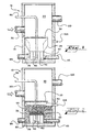
- a filter apparatus 10 includes an outer fluid container 15.
- Outer fluid containment housings include concrete containers, earthen basins, natural water features (including a lake), and like environments in which fluid to be filtered may be contained.
- An influent pipe 20 provides fluid to be filtered into the outer container 15. It will-be appreciated that the influent pipe 20 may be located in a variety of positions (such as above or below the top of the filter) and or/include a plurality of influent pipes 20.
- FIG. 1 depicts the filter media housing 25 comprising a flexible membrane in both expanded and compressed embodiments to demonstrate compressibility of the housing.
- the top of the filter media housing 25 includes an upper perforated plate 30 to allow fluid to be filtered into the housing, as well as backwash fluid out of the housing, while retaining the filter media within housing (such as during backwash processes subsequently described).
- a housing base 35 secures the filter media housing 25 at the bottom of the outer container 15.
- the base may include baffles 40 that direct filtered fluid to an effluent pipe 45 carrying filtered fluid from the filter housing 25 out of the containment 15.
- the baffles 40 may also direct air and make-up water to the center of lower perforated plate 50 during backwashing operations ( FIG. 5 ).
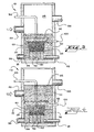
- the containment 15 may include a plurality of filter units 11 wherein the base may be a wall of an effluent channel/conveyance 45A or a piping network underlying one or more filter units 11.
- the channel wall or piping serves as the base to support one or more filter units 11 is an upright position within the outer containment 15.
- the integrated filter unit 11 into the conveyance 45A may be provided without baffles 40.
- the underlying effluent conveyances (or piping) 45A may all connect to a larger effluent conveyance 45B for carrying off filtered fluid.
- underlying conveyances 45A may be directed to other desired locations and conveyance points.
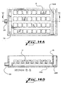
- FIGS 14A and 14B also show that one or more backwash pumps 72 may be provided for removing backwash fluid from the containment 15 following the backwash process (subsequently described).
- each of the filter units 11 includes compressible media 60 and a filter media housing 25 and operates as subsequently described with reference to a single filter unit.
- the lower perforated plate 50 allows filtered fluid to exit the flexible housing 25.
- the lower perforated plate 50 also supports filter media 60 ( FIG. 2 ) within the housing 25.
- compressible filter media 60 is housed within the housing 25 between the upper perforated plate 30 and lower perforated plate 50.
- filter bundles disclosed in U.S. Pat. No. 5,248,415 to Masuda et al . and U.S. Patent Application Publication No. US2003/0111431 are particularly adapted for use as filter media 60 in the present invention, a variety of compressible fibrous filter elements may be used.
- the fibrous media 60 of the present invention improves upon the prior art through the use of multi-component fibers where two or more synthetic materials are used in the same fiber to achieve the physical characteristics such as specific gravity, resilience, chemical resistance, stiffness, fiber diameter, and the like.
- the filter media fiber may further include components with specifically desired performance characteristics such as specific pollutant removal capabilities.
- oleophilic fiber components may be used in embodiments for attracting oil from fluid being filtered or hydrophobic fibers may be used to encourage water filtration.
- the fiber is manufactured with a nylon inner core and polypropylene outer cover.
- the fiber is manufactured using a polyester inner core with a polypropylene sheath.
- the multi-component fiber is a bi-component fiber, wherein an inner fiber 65 and an outer fiber 67 (sheath) are provided/extruded in a generally concentric configuration.
- the components are generally eccentric with the inner component 65 being off-center.
- the eccentric configuration permits heating of the fiber to produce crimping based on the resultant heat distortion.
- a plurality of inner fibers 65 may be contained in a sheath 67, such as shown in FIG. 11 .
- the plurality of inner fibers 65 may be the same or different component materials.
- one or more additional outer sheaths could be provided in alternative embodiments to achieve specific pollutant removal as well as exhibit desired physical characteristics.
- core and sheath materials may include any combination of the following, or other synthetic fibers: polyester (PET), coPET, polylactic acid (PLA), polytrimethylene terephthalate, polycyclohexanediol terephthalate (PCT), polyethylene napthalate (PEN); high density polyethylene (HDPE), linear low density polyethylene (LLDPE), polyethylene (PE), polypropylene (PP), PE/PP copolymer, nylon, polyvinylidene fluoride (PVDF), polytetrafluoroethylene (PTFE) and polyurethane.
- polyester PET
- coPET polylactic acid
- PLA polytrimethylene terephthalate
- PCT polycyclohexanediol terephthalate
- PEN polyethylene napthalate
- HDPE high density polyethylene
- LLDPE linear low density polyethylene
- PE polyethylene
- PP polypropylene
- PE/PP copolymer nylon
- PVDF polyvinylidene fluoride
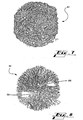
- the fibers used as filter media 60 are initially in the form of loosely packed elongated fibers 70 on spools 75.
- FIG. 6 With continuing reference to FIG. 6 , several bundles of elongated fibers 70 are brought together from the spools 75 using a reducing device 80.
- the device 80 reduces the overall size of the fibers while a hog ring fastener/binding wire 85 or other similar clamp is applied. After the clamps are applied, the fiber bundles are cut at cut lines 90 between each clamp 85 to form a fibrous lump 61 ( FIGS. 7 and 8 ).
- the multi-component fibers can be crimped mechanically and/or by heating.
- a mechanical crimping machine is used in one method. Following extrusion, the fibers are mechanically crimped along the length of the fibers to produce crimped fiber.
- a second method is to produce the multi-component fiber 65 such that the core materials are placed eccentrically from the sheath 65 ( FIG. 10 ). When heat is applied, the fiber materials distort differently resulting in a helically shaped crimp. The amount of heat applied is dependent on the fiber materials.
- fluid 22 to be filtered enters from the influent pipe 20 and fills the void 28 between the outer container 15 and flexible housing 25.
- the air inlet 90 is off.
- the drain 95 is closed.
- initial compression of the filter media is adjustable and can be set by the level of fluid and media inside the filter media housing 25 at the beginning of the filter run.
- the media After backwashing (see FIG. 5 and related description), the media is in a relatively uniform suspension with density equal to the number of filter media bundles 61 per volume of fluid within the flexible membrane 25.
- a lower fluid level inside the flexible membrane 25 will result in a greater density of filter media 60 and thus a greater initial compression when the void space 28 begins to fill and the flexible membrane 25 compresses the filter media 60.
- a higher fluid level left inside the flexible membrane 25 at the beginning of the filter cycle will result in a lower initial compression.
- Initial compression is shown in FIG. 2 . During this initial filling, it will be appreciated that the flexible housing 25 is relatively expanded until the hydrostatic pressure outside the housing 25 exceeds the pressure within the housing 25.
- fluid 22 rises above the upper perforated plate 30 of the flexible membrane housing 25, the fluid 22 enters the top perforated plate 30 for filtering by the filter media 60.
- the fluid being filtered 22 passes downward through the filter media 60 with particulates being removed from the fluid.
- particulates are removed nearer the top of the filter bed with smaller particulates removed deeper in the media bed and as solids begin to bridge the voids between the media fibers a matting takes place resulting in removal of both fine and larger particles in the upper media zone ( FIG. 12 ).
- less compression with media open to the fluid being filtered 22 results in the upper zone of the media bed and more compression results in the lower zone.
- the filter bed becomes more effective in removing a larger amount of particulates per unit of media and protect the finer particulates from passing through the filter.
- the compression differential described above between the upper and bottom zones of the media bed is created in the initial compression developed after backwashing or during initial filter operation.
- initial compression shows the lower filter media bed 60B to be compressed inward by the filter media housing 25.
- the upper filter media bed 60A is relatively uncompressed as the housing 25, in embodiments where the housing is a flexible membrane, remains tight and relatively inflexible at the upper portion of the housing 25 between upper plate 30 and a taper point 27.
- the filter media housing 25 may include a plurality of components to achieve the similar effect of multiple compression zones.
- the upper portion of the housing 25 may comprise a rigid element connected to a lower membrane (lower portion of housing 25 ).
- the upper filter media 60A in such embodiment would be uncompressed from the external fluid as the rigid upper portion would not flex inward.
- the flexible lower portion of the filter membrane would be compressible by the outer fluid to generate compressed lower bed 60B.
- the housing 25 could include a lower housing portion with hinged plate walls instead of a flexible membrane.
- the hinged wall could be provided with a hinge near taper point 27, wherein the upper portion of the housing 25 would be a relatively rigid component.
- Such walls could be provided in a variety of shapes, including flat wall plates with leak-resistant membranes or materials joining one plate to the next plate. Sliding mechanisms may also be used for a portion of the housing to compress inward. It will be appreciated that all such embodiments permit the external fluid pressure to compress the lower portion of the housing and the lower filter media bed 60B inward.
- the housing 25 may be constructed of single or multi-ply membranes of chlorosulfonated polyethylene (Hypalon), polyvinyl chloride (PVC), rubber, viton, polypropylene, polyethylene, vinyl, neoprene, polyurethane and woven and non-woven fabrics.
- construction materials could include steel, stainless steel, other metals, reinforced and unreinforced plastics.
- the filter media housing 25 may be constructed of any suitable material depending on the desired filtering use, types of fluids being filtered, desired corrosive characteristics and the like.
- the present invention is shown in embodiments with external fluid pressure generating compressive force against the housing 25 and filter media 60, other external forces may also, or additionally, be used to compress the lower filter media bed 60B.
- the side walls of the housing 25 may be actuated in an inwardly pivotable or sliding manner through mechanical, electrical, hydraulic and similar operation.
- inflatable components may be provided external to the housing and inflated in a balloon-like manner to press against the housing and compress the filter media.
- the top surface of the filter media bed 60 includes space 62 (see also FIGS. 2-4 ) that is open and untouched by the upper perforated plate.
- the upper filter media zone 60A remains uncompressed by not only the housing 25, but also avoids external top to down compression from the upper plate 30 because of spacing 62.
- the initial compression with relatively uncompressed upper filter media bed 60A with an open surface and the compressed lower filter media bed 60B will result in greater particulate penetration than if the upper filter media bed 60A were compressed or the entire bed were compressed. Finer particulates may therefore be captured in the lower media bed 60B as greater penetration is achieve. It is thus an object of the present invention to maximize fluid filtering efficiency.
- the flexible housing 25 shape is also generally wider at the upper portion than at the lower portion of the housing 25. It will be appreciated that in such embodiments, less filter media 60 is required at the bottom as the filter bed narrows to direct the fluid out of the housing 25 and the fluid 22 being filtered is "cleaner" toward the bottom. Further, the generally tapered embodiment provides additional filter benefits as the media is more loosely packed near the more "open” upper portion and is more densely packed nearer the bottom portion of the housing.
- different compression levels may be created by higher media concentrations with lower inner fluid levels.
- Different filter materials and combinations of materials with desired physical properties may also be used to achieve different compression levels, including the layering of filter media with different densities, compressibility or other desired physical and performance characteristics to achieve a desired filter bed that may include one or more zones.
- FIG. 3 shows the hydraulic head in the upstream portions outside the flexible housing 25 becoming greater than the downstream hydrostatic pressure.
- the hydraulic head differential is due to both the flow stream through the filter media 60 and the build-up of particles on the filter media 60, resulting in increasing upstream fluid level as solids are removed ( FIGS. 3 and 4 ).
- the housing 25 is further compressed inward, thereby further compressing the filter media 60.
- the housing 25 and filter media 60 are compressed in a direction non-parallel, including generally perpendicular in some embodiments ( FIGS. 2-4 and 12 ), to the direction of the fluid flow through the filter media.
- a plurality of compression zones may be established, such as lower portion of the filter media bed 60B being compressed to remove finer particulates and protect the filter media bed 60 from particle breakthrough.
- FIG. 4 an embodiment of the invention is shown when the filtration cycle has reached its latter stages and/or during a period of peak upstream fluid flow.
- the latter stage of the filtration cycle is reached when the filter media 60 captures its maximum particle load, and the depth of fluid 22 over the top of the upper perforated plate 30 reaches it maximum fluid level.
- the filter cycle continues whereby fluid 22 is both filtered through the media bed 60 and a portion of the fluid bypasses the filter and is discharged from the outer housing 15 along with the filtered effluent 45.
- filtration of wet weather flows such as treatment of stormwater or treatment of wet weather discharges from sewer systems, can be designed to remove a specific particle load according to a desired need for a particular event, and after the load is reached or the design flow rate is reached, excess flows and excess particle loads may be discharged from the filter.
- FIG. 5 shows the filter media 60 being backwashed to remove particulate build up.
- a backwash outlet such as a backwash pump discharge 105 connected to a backwash pump 72 ( FIG. 14A ) can be used to remove the backwashed particles from the containment housing 15 or the backwashed fluid can be removed from the containment 15 by opening a drainpipe 95.
- the fluid level within the containment housing 15 is lower than the water level within the filter media housing 25 causing the housing 25 to expand.
- an air inlet 90 provides air from a blower at the base portion 35 or under the lower perforated plate 50. It will be appreciated that the backwashed fluid containing the concentrated particulates from the fluid to be filtered 22 is typically transferred to a sanitary sewer system for further treatment, removed by vacuum vehicle equipment for transport to other facilities for further process or by further processing the backwash fluid on-site by other concentrating and dewatering processes.
- the air from the air inlet 90 enters the center section of the base 35 and rises through the center of the lower perforated plate 50 and up through the center of the filter media 60.
- the upward center air flow causes the filter media 60 to circulate within the expanded filter media housing 25 during the washing cycle. Circulation of the filter media 60 causes the media 60 to collide with the upper perforated plate 35 and with other media bundles 60, helping particulates to dislodge.
- the lower specific gravity of the air/fluid mixture or the hydraulic head of the backwash water within the housing 25 causes the fluid level within the housing 25 to rise and flow over the upper perforated plate 30 into the void 28 inside of the outer container 15 and outside the housing 25.
- the backwash fluid exits containment 15 by either gravity drainage through drain 95 or pumping through outlet 105.
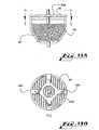
- FIGS. 13A and 13B Another embodiment, shown in FIGS. 13A and 13B , includes backwash removal device 200 having troughs 201, placed on the upper perforated plate 30.
- troughs 201 form a donut-shape around the center of the air inlet on the upper perforated plate 30.
- the troughs 201 receive the backwash fluid with concentrated particulates as the backwash fluid rises above the perforated plate 30 (through the action of centrally directed air) and is directed through the radial troughs 201 to the void 28, thus minimizing particulate recirculation during the backwash mode.
- the quicker the backwash fluid is separated from the circulating media the less make-up water is required to clean the filter and the shorter the backwashing cycle time.
- water level in the center of the upper plate 30 is at the highest level caused by the central rising air and this hydraulic head is used to drive the backwash fluid through the radial toughs 201 into the void 28 for removal.
- a drain 95 is provided at the bottom of the outer container 15.
- the drain 95 can also be opened to remove fluid from inside the outer container 15, such as following backwashing. Further, the void 28 between the outer container 15 and housing 25 can be cleaned, and the drain 95 opened to remove the cleaning fluid. It will be appreciated that a plurality of drains 95 may also be provided.
- the backwash removal device 200 can be designed with troughs 201 being enclosed, for example, using pipes to carry backwash water out of the outer containment 15.
- outer containment structures such as earthen basins with permanent lower water levels or natural water features (such as lakes)
- the outer containment 15 would not be drained and it may be desired that backwash water be discharged outside of the outer containment 15.
- the compressible media housing 25 may be actuated inwards or outwards by an inflatable balloon or similar alternative method as described previously.
- the fluid inlet to the filter may be closed when backwashing occurs.
Abstract
Description
- The present invention relates to the filtering of particulates from fluids, particularly the removal of solids from water, using compressible filter media in a compressible housing.
- Prior art techniques using compressible media have relied on mechanically actuated plates to externally compress filter media.
- For example,
U.S. Pat. No. 5,248,415 to Masuda et al . discloses the use of fibrous filter media compressed by a movable bottom plate in a bottom-up filtration apparatus. - U.S. Patent Application Publication No.
US2003/0111431 discloses fibrous filter media compressed by a movable top plate in a bottom-up filtration apparatus.U.S. Pat. No. 4,776,962 discloses a fibrous filter media compressed by a movable top plate in a downflow filtration apparatus. - In such prior art apparatuses, the movable plate compresses the filter media within rigid containment walls during filtration and provides compression across the entire filter media bed. Compression of the media increases the filtering performance measured as percent removal and removal of smaller particulates; however, particulate rapidly builds up in the initial portion of the media bed and reduces the filter operation time. Filtering efficiency progressively decreases as a result of the particulate accumulation, and eventually filtering must be stopped to wash and dislodge the solid build up. The movable plate pressed against the media further inhibits the capacity of the initial portion of the media bed to remove particulates resulting in shorter filter operation time and less solid removal per unit of filter media. The washing operation requires that the movable plate be retracted so that air and washing fluid may be directed through the media to scrub and dislodge the solids. The media is re-compressed with the movable plate when filtering is restarted. The movable plates require close tolerance with the rigid containment walls to retain filter media and maintain efficient filter and backwashing operations.
- Accordingly, there is a need for a filter apparatus and method that provides efficient filtration with compressed media that improves particulate capture with longer filter operation times, but eliminates the need for mechanically movable plates, close tolerance containment walls and associated mechanisms.
-
US 5,470,470 andUS 4,851,136 each discuss filter devices similar to the present disclosure, and in line with the preamble ofclaim 1.US 5,470,470 describes a filter housing which is compressed by mechanical means;US 4,851.136 discusses a filter device comprising filter bundles which are surrounded by a flexible waterproof membrane. Neither of these documents relates to a filter device in which the filter media is compressed by means of the fluid to be filtered. - The present invention provides a filter device in accordance with
independent claim 1, and a method of filtering a fluid as described inindependent claim 23. Further preferred embodiments are given in the dependent claims. - The claimed invention can be better understood in view of the embodiments of the filter device and method described hereinafter. In general, the described embodiments describe preferred embodiments of the invention. The attentive reader will note, however, that some aspects of the described embodiments extend beyond the scope of the claims. To the respect that the described embodiments indeed extend beyond the scope of the claims, the described embodiments are to be considered supplementary background information and do not constitute definitions of the invention per se. This also holds for the subsequent "Brief Description of the Drawings" as well as the "Detailed Description of the Invention."
-
-
FIG. 1 is a schematic cross-sectional view of a single filter apparatus of the present invention showing a flexible housing for containing filter media in an embodiment of the present invention. -
FIG. 2 is a schematic cross-sectional view of a filter apparatus of the present invention during initial filling with fluid to be filtered. -
FIG. 3 is a schematic cross-sectional view of a filter apparatus of the present invention as the hydraulic head becomes greater upstream than in the downstream flow and the hydrostatic pressure of the unfiltered fluid compresses the flexible housing in an embodiment of the invention. -
FIG. 4 is a schematic cross-sectional view of a filter apparatus of the present invention as influent level reaches an optional overflow pipe in an embodiment of the invention. -
FIG. 5 is a schematic cross-sectional view of a filter apparatus of the present invention during backwash operation in an embodiment of the invention. -
FIG. 6 is a schematic view of fiber being reduced from spools and bound for cutting into fiber media bundles in an embodiment of the invention. - -
FIG. 7 is a front perspective view of a filter media bundle in an embodiment of the invention. -
FIG. 8 is a cross-sectional view of a filter media element including a hog ring/binding wire crimping and holding the center of the filter media bundle fibers in an embodiment of the invention. -
FIG. 9 is a schematic cross-sectional view of a concentric bi-component fiber in an embodiment of the invention. -
FIG. 10 is a schematic cross-sectional view of an eccentric bi-component fiber in an embodiment of the invention. -
FIG. 11 is a schematic cross-sectional view a multi-component fiber in an embodiment of the invention. -
FIG. 12 is a schematic cross-sectional view depicting first and second compression zones of compressible filter media in a filter media housing in an embodiment of the invention. -
FIG. 13A is a schematic cross-sectional view of a filter media housing including uncompressed filter media and a backwash removal device in an embodiment of the invention. -
FIG. 13B is a schematic top plan view of a backwash removal device along line I-I ofFIG. 13A in an embodiment of the invention. -
FIG. 14A is a schematic top plan view of a plurality of filter units within a large fluid containment in an embodiment of the invention. -
FIG. 14B is a schematic cross-sectional view of a plurality of filter units along line II-II ofFIG. 14A . - The present invention provides an apparatus and method for filtering fluids with compressible filter media contained in a flexible housing. In the described embodiments, fluid outside the housing compresses the housing and filter media; however, it will be appreciated that a variety of external forces may be applied to the outer housing and compressible media to achieve the objectives of the invention in other embodiments. It will also be appreciated that although the invention is described in embodiments for top to down filtering of fluid, the apparatuses and components described herein may be positioned such that the filtration may occur in other directions, and repositioning is within the scope of the invention.
- The present invention thus provides improved filtration, and is particularly adapted for the filtration of stormwater, drinking water and wastewater. Those skilled in the art will further appreciate that in other embodiments the present invention is adapted for use with a variety of fluids and filtering applications.
- Referring to
FIG. 1 , in an embodiment of the present invention afilter apparatus 10 includes anouter fluid container 15. Outer fluid containment housings include concrete containers, earthen basins, natural water features (including a lake), and like environments in which fluid to be filtered may be contained. Aninfluent pipe 20 provides fluid to be filtered into theouter container 15. It will-be appreciated that theinfluent pipe 20 may be located in a variety of positions (such as above or below the top of the filter) and or/include a plurality ofinfluent pipes 20. - Within the
outer container 15 an uprightfilter media housing 25 is provided.FIG. 1 depicts thefilter media housing 25 comprising a flexible membrane in both expanded and compressed embodiments to demonstrate compressibility of the housing. The top of thefilter media housing 25 includes an upperperforated plate 30 to allow fluid to be filtered into the housing, as well as backwash fluid out of the housing, while retaining the filter media within housing (such as during backwash processes subsequently described). - A
housing base 35 secures thefilter media housing 25 at the bottom of theouter container 15. - In one embodiment, the base may include
baffles 40 that direct filtered fluid to aneffluent pipe 45 carrying filtered fluid from thefilter housing 25 out of thecontainment 15. Thebaffles 40 may also direct air and make-up water to the center of lowerperforated plate 50 during backwashing operations (FIG. 5 ). - Referring to
FIGS. 14A and 14B , in other exemplary embodiments, thecontainment 15 may include a plurality offilter units 11 wherein the base may be a wall of an effluent channel/conveyance 45A or a piping network underlying one ormore filter units 11. In such embodiments, the channel wall or piping serves as the base to support one ormore filter units 11 is an upright position within theouter containment 15. Theintegrated filter unit 11 into theconveyance 45A may be provided withoutbaffles 40. - In a large containment environment as shown in
FIGS. 14A and 14B , the underlying effluent conveyances (or piping) 45A may all connect to a larger effluent conveyance 45B for carrying off filtered fluid. In otherembodiments underlying conveyances 45A may be directed to other desired locations and conveyance points. -
FIGS 14A and 14B , also show that one or more backwash pumps 72 may be provided for removing backwash fluid from thecontainment 15 following the backwash process (subsequently described). - In embodiments utilizing a plurality of
filter units 11, it will be appreciated that thecontainment 15 may include a large basin, natural feature, manmade containments and the like, where a large quantity of fluid is to be filtered. It will also be appreciated each of thefilter units 11 includescompressible media 60 and afilter media housing 25 and operates as subsequently described with reference to a single filter unit. - Referring again to
FIG. 1 , between theupper plate 30 andbase 35, the lowerperforated plate 50 allows filtered fluid to exit theflexible housing 25. The lowerperforated plate 50 also supports filter media 60 (FIG. 2 ) within thehousing 25. - With further reference to
FIG. 2 andFIGS. 7-11 ,compressible filter media 60 is housed within thehousing 25 between the upperperforated plate 30 and lowerperforated plate 50. Although the filter bundles disclosed inU.S. Pat. No. 5,248,415 to Masuda et al . and U.S. Patent Application Publication No.US2003/0111431 are particularly adapted for use asfilter media 60 in the present invention, a variety of compressible fibrous filter elements may be used. - In certain embodiments, the
fibrous media 60 of the present invention improves upon the prior art through the use of multi-component fibers where two or more synthetic materials are used in the same fiber to achieve the physical characteristics such as specific gravity, resilience, chemical resistance, stiffness, fiber diameter, and the like. In other embodiments, the filter media fiber may further include components with specifically desired performance characteristics such as specific pollutant removal capabilities. For example, oleophilic fiber components may be used in embodiments for attracting oil from fluid being filtered or hydrophobic fibers may be used to encourage water filtration. Those skilled in the art will appreciate that a wide variety of other combinations of components in the filter media may be adapted for use in the present invention depending on the desired performance the type of fluid and pollutants being filtered. - In one embodiment to achieve a chemically resistant fibrous lump of low resilience and lower specific gravity, the fiber is manufactured with a nylon inner core and polypropylene outer cover.
- In another embodiment to obtain a heavier, more resilient lump 61 (
FIGS. 7 and 8 ), the fiber is manufactured using a polyester inner core with a polypropylene sheath. - Referring to
FIG. 9 , in one embodiment the multi-component fiber is a bi-component fiber, wherein aninner fiber 65 and an outer fiber 67 (sheath) are provided/extruded in a generally concentric configuration. - Referring to
FIG. 10 , in another embodiment the components are generally eccentric with theinner component 65 being off-center. In such embodiment, subsequently described, the eccentric configuration permits heating of the fiber to produce crimping based on the resultant heat distortion. - It will be appreciated that in alternative embodiments a plurality of
inner fibers 65 may be contained in asheath 67, such as shown inFIG. 11 . In such embodiments, the plurality ofinner fibers 65 may be the same or different component materials. It will also be appreciated that one or more additional outer sheaths could be provided in alternative embodiments to achieve specific pollutant removal as well as exhibit desired physical characteristics. - In various embodiments, core and sheath materials may include any combination of the following, or other synthetic fibers: polyester (PET), coPET, polylactic acid (PLA), polytrimethylene terephthalate, polycyclohexanediol terephthalate (PCT), polyethylene napthalate (PEN); high density polyethylene (HDPE), linear low density polyethylene (LLDPE), polyethylene (PE), polypropylene (PP), PE/PP copolymer, nylon, polyvinylidene fluoride (PVDF), polytetrafluoroethylene (PTFE) and polyurethane.
- Referring to
FIG. 6 , the fibers used asfilter media 60 are initially in the form of loosely packedelongated fibers 70 onspools 75. - With continuing reference to
FIG. 6 , several bundles ofelongated fibers 70 are brought together from thespools 75 using a reducingdevice 80. Thedevice 80 reduces the overall size of the fibers while a hog ring fastener/bindingwire 85 or other similar clamp is applied. After the clamps are applied, the fiber bundles are cut atcut lines 90 between eachclamp 85 to form a fibrous lump 61 (FIGS. 7 and 8 ). - In embodiments of the invention, the multi-component fibers can be crimped mechanically and/or by heating.
- A mechanical crimping machine is used in one method. Following extrusion, the fibers are mechanically crimped along the length of the fibers to produce crimped fiber. A second method is to produce the
multi-component fiber 65 such that the core materials are placed eccentrically from the sheath 65 (FIG. 10 ). When heat is applied, the fiber materials distort differently resulting in a helically shaped crimp. The amount of heat applied is dependent on the fiber materials. - Referring again to
FIG. 2 , during initial filling, fluid 22 to be filtered enters from theinfluent pipe 20 and fills the void 28 between theouter container 15 andflexible housing 25. Theair inlet 90 is off. Thedrain 95 is closed. - With continuing reference to
FIG. 2 , initial compression of the filter media is adjustable and can be set by the level of fluid and media inside thefilter media housing 25 at the beginning of the filter run. After backwashing (seeFIG. 5 and related description), the media is in a relatively uniform suspension with density equal to the number of filter media bundles 61 per volume of fluid within theflexible membrane 25. A lower fluid level inside theflexible membrane 25 will result in a greater density offilter media 60 and thus a greater initial compression when thevoid space 28 begins to fill and theflexible membrane 25 compresses thefilter media 60. A higher fluid level left inside theflexible membrane 25 at the beginning of the filter cycle will result in a lower initial compression. Initial compression is shown inFIG. 2 . During this initial filling, it will be appreciated that theflexible housing 25 is relatively expanded until the hydrostatic pressure outside thehousing 25 exceeds the pressure within thehousing 25. - With further reference to
FIGS. 3 and12 ,fluid 22 rises above the upperperforated plate 30 of theflexible membrane housing 25, the fluid 22 enters the topperforated plate 30 for filtering by thefilter media 60. The fluid being filtered 22 passes downward through thefilter media 60 with particulates being removed from the fluid. It will be appreciated that, in general, larger particulates are removed nearer the top of the filter bed with smaller particulates removed deeper in the media bed and as solids begin to bridge the voids between the media fibers a matting takes place resulting in removal of both fine and larger particles in the upper media zone (FIG. 12 ). It will also be appreciated that less compression with media open to the fluid being filtered 22 results in the upper zone of the media bed and more compression results in the lower zone. Because of the compression zones, the filter bed becomes more effective in removing a larger amount of particulates per unit of media and protect the finer particulates from passing through the filter. The compression differential described above between the upper and bottom zones of the media bed is created in the initial compression developed after backwashing or during initial filter operation. - With continuing reference to
FIG. 12 , initial compression shows the lowerfilter media bed 60B to be compressed inward by thefilter media housing 25. The upperfilter media bed 60A is relatively uncompressed as thehousing 25, in embodiments where the housing is a flexible membrane, remains tight and relatively inflexible at the upper portion of thehousing 25 betweenupper plate 30 and ataper point 27. - In other embodiments the
filter media housing 25 may include a plurality of components to achieve the similar effect of multiple compression zones. For example, the upper portion of thehousing 25 may comprise a rigid element connected to a lower membrane (lower portion of housing 25). Theupper filter media 60A in such embodiment would be uncompressed from the external fluid as the rigid upper portion would not flex inward. The flexible lower portion of the filter membrane would be compressible by the outer fluid to generate compressedlower bed 60B. - In still other embodiments, the
housing 25 could include a lower housing portion with hinged plate walls instead of a flexible membrane. In such embodiments, the hinged wall could be provided with a hinge neartaper point 27, wherein the upper portion of thehousing 25 would be a relatively rigid component. Such walls could be provided in a variety of shapes, including flat wall plates with leak-resistant membranes or materials joining one plate to the next plate. Sliding mechanisms may also be used for a portion of the housing to compress inward. It will be appreciated that all such embodiments permit the external fluid pressure to compress the lower portion of the housing and the lowerfilter media bed 60B inward. - In embodiments where the
housing 25 is flexible, it may be constructed of single or multi-ply membranes of chlorosulfonated polyethylene (Hypalon), polyvinyl chloride (PVC), rubber, viton, polypropylene, polyethylene, vinyl, neoprene, polyurethane and woven and non-woven fabrics. In embodiments where rigid materials are used, such as those including an upper rigid portion or including pivotable or sliding housing walls, construction materials could include steel, stainless steel, other metals, reinforced and unreinforced plastics. It will be appreciated, however, that thefilter media housing 25 may be constructed of any suitable material depending on the desired filtering use, types of fluids being filtered, desired corrosive characteristics and the like. - It will also be appreciated that although the present invention is shown in embodiments with external fluid pressure generating compressive force against the
housing 25 andfilter media 60, other external forces may also, or additionally, be used to compress the lowerfilter media bed 60B. For example, in other embodiments, the side walls of thehousing 25 may be actuated in an inwardly pivotable or sliding manner through mechanical, electrical, hydraulic and similar operation. In other embodiments, inflatable components may be provided external to the housing and inflated in a balloon-like manner to press against the housing and compress the filter media. - Referring again to
FIG. 12 , the top surface of thefilter media bed 60 includes space 62 (see alsoFIGS. 2-4 ) that is open and untouched by the upper perforated plate. In such embodiment, the upperfilter media zone 60A remains uncompressed by not only thehousing 25, but also avoids external top to down compression from theupper plate 30 because ofspacing 62. It will also be appreciated that the initial compression with relatively uncompressed upperfilter media bed 60A with an open surface and the compressed lowerfilter media bed 60B will result in greater particulate penetration than if the upperfilter media bed 60A were compressed or the entire bed were compressed. Finer particulates may therefore be captured in thelower media bed 60B as greater penetration is achieve. It is thus an object of the present invention to maximize fluid filtering efficiency. - Referring further to
FIGS. 3 and 4 , as filtration proceeds and more particulates are removed, the hydraulic head differential across the filter becomes greater (FIG. 3 to FIG. 4 ) causing greater compression in thelower zone 60B to prevent smaller particulates from passing through. There is also a slight upheaval ofupper media zone 60A as thelower zone 60B compresses to allow more particulates to enter thefilter media 60. Compression of thefilter media 60, as described with reference toFIGS. 3 and 4 , thus improves filtering as increasingly smaller and more particulate is removed in thefilter media bed 60. - In embodiments of the invention, the
flexible housing 25 shape is also generally wider at the upper portion than at the lower portion of thehousing 25. It will be appreciated that in such embodiments,less filter media 60 is required at the bottom as the filter bed narrows to direct the fluid out of thehousing 25 and the fluid 22 being filtered is "cleaner" toward the bottom. Further, the generally tapered embodiment provides additional filter benefits as the media is more loosely packed near the more "open" upper portion and is more densely packed nearer the bottom portion of the housing. - In other embodiments, it will be appreciated that in addition to or instead of tapering housing shapes, different compression levels may be created by higher media concentrations with lower inner fluid levels. Different filter materials and combinations of materials with desired physical properties may also be used to achieve different compression levels, including the layering of filter media with different densities, compressibility or other desired physical and performance characteristics to achieve a desired filter bed that may include one or more zones.
-
FIG. 3 shows the hydraulic head in the upstream portions outside theflexible housing 25 becoming greater than the downstream hydrostatic pressure. The hydraulic head differential is due to both the flow stream through thefilter media 60 and the build-up of particles on thefilter media 60, resulting in increasing upstream fluid level as solids are removed (FIGS. 3 and 4 ). As the hydrostatic pressure outside thefilter media housing 25 becomes greater than the hydrostatic pressure inside thehousing 25, thehousing 25 is further compressed inward, thereby further compressing thefilter media 60. In embodiments of the invention, thehousing 25 andfilter media 60 are compressed in a direction non-parallel, including generally perpendicular in some embodiments (FIGS. 2-4 and12 ), to the direction of the fluid flow through the filter media. And as also shown inFIG. 12 , and previously described, a plurality of compression zones may be established, such as lower portion of thefilter media bed 60B being compressed to remove finer particulates and protect thefilter media bed 60 from particle breakthrough. - Referring to
FIG. 4 , an embodiment of the invention is shown when the filtration cycle has reached its latter stages and/or during a period of peak upstream fluid flow. The latter stage of the filtration cycle is reached when thefilter media 60 captures its maximum particle load, and the depth offluid 22 over the top of the upperperforated plate 30 reaches it maximum fluid level. - In one embodiment of the invention, when the fluid 22 over the
filter apparatus 10 reaches it maximum fluid level, closing the influent 20 stops the filter cycle. In this embodiment the backwashing cycle (FIG. 5 ) is initiated. - In another embodiment of the invention where an
overflow pipe 100 is provided, the filter cycle continues wherebyfluid 22 is both filtered through themedia bed 60 and a portion of the fluid bypasses the filter and is discharged from theouter housing 15 along with the filteredeffluent 45. It will be appreciated that filtration of wet weather flows, such as treatment of stormwater or treatment of wet weather discharges from sewer systems, can be designed to remove a specific particle load according to a desired need for a particular event, and after the load is reached or the design flow rate is reached, excess flows and excess particle loads may be discharged from the filter. -
FIG. 5 shows thefilter media 60 being backwashed to remove particulate build up. During a backwash operation fluid entry from theinfluent pipe 20 is stopped. Make-upwater 23 is introduced into thefilter effluent pipe 45 or to an open-close connection valve to the outer section of thehousing base portion 35. A backwash outlet, such as abackwash pump discharge 105 connected to a backwash pump 72 (FIG. 14A ), can be used to remove the backwashed particles from thecontainment housing 15 or the backwashed fluid can be removed from thecontainment 15 by opening adrainpipe 95. During backwash the fluid level within thecontainment housing 15 is lower than the water level within thefilter media housing 25 causing thehousing 25 to expand. - In the backwash cycle, an
air inlet 90, provides air from a blower at thebase portion 35 or under the lowerperforated plate 50. It will be appreciated that the backwashed fluid containing the concentrated particulates from the fluid to be filtered 22 is typically transferred to a sanitary sewer system for further treatment, removed by vacuum vehicle equipment for transport to other facilities for further process or by further processing the backwash fluid on-site by other concentrating and dewatering processes. - The air from the
air inlet 90 enters the center section of thebase 35 and rises through the center of the lowerperforated plate 50 and up through the center of thefilter media 60. The upward center air flow causes thefilter media 60 to circulate within the expandedfilter media housing 25 during the washing cycle. Circulation of thefilter media 60 causes themedia 60 to collide with the upperperforated plate 35 and with other media bundles 60, helping particulates to dislodge. The lower specific gravity of the air/fluid mixture or the hydraulic head of the backwash water within thehousing 25 causes the fluid level within thehousing 25 to rise and flow over the upperperforated plate 30 into the void 28 inside of theouter container 15 and outside thehousing 25. The backwash fluid exitscontainment 15 by either gravity drainage throughdrain 95 or pumping throughoutlet 105. - Another embodiment, shown in
FIGS. 13A and 13B , includesbackwash removal device 200 havingtroughs 201, placed on the upperperforated plate 30. In this embodiment,troughs 201 form a donut-shape around the center of the air inlet on the upperperforated plate 30. Thetroughs 201 receive the backwash fluid with concentrated particulates as the backwash fluid rises above the perforated plate 30 (through the action of centrally directed air) and is directed through theradial troughs 201 to the void 28, thus minimizing particulate recirculation during the backwash mode. It can be appreciated that the quicker the backwash fluid is separated from the circulating media, the less make-up water is required to clean the filter and the shorter the backwashing cycle time. It can also be appreciated that water level in the center of theupper plate 30 is at the highest level caused by the central rising air and this hydraulic head is used to drive the backwash fluid through theradial toughs 201 into the void 28 for removal. - In another embodiment, a
drain 95 is provided at the bottom of theouter container 15. Thedrain 95 can also be opened to remove fluid from inside theouter container 15, such as following backwashing. Further, the void 28 between theouter container 15 andhousing 25 can be cleaned, and thedrain 95 opened to remove the cleaning fluid. It will be appreciated that a plurality ofdrains 95 may also be provided. - In another embodiment, the
backwash removal device 200 can be designed withtroughs 201 being enclosed, for example, using pipes to carry backwash water out of theouter containment 15. It can be appreciated that in certain outer containment structures such as earthen basins with permanent lower water levels or natural water features (such as lakes), theouter containment 15 would not be drained and it may be desired that backwash water be discharged outside of theouter containment 15. It can be further appreciated that in this application thecompressible media housing 25 may be actuated inwards or outwards by an inflatable balloon or similar alternative method as described previously. It can be further appreciated that in an application where theouter containment 15 is a natural water feature with a fixed water level, the fluid inlet to the filter may be closed when backwashing occurs. - Accordingly, while the invention has been described with reference to the structures and processes disclosed, it is not confined to the details set forth, but is intended to cover such modifications or changes as may fall within the scope of the following claims.
Claims (31)
- An apparatus (10) for filtering fluids (22) comprising an outer fluid container (15) and a compressible housing (25) containing a compressible filter media bed (60),
characterized in that:the outer fluid container (15) includes an influent pipe (20) through which fluid (22) to be filtered flows into the outer fluid container (15), the housing (25), located within the outer fluid container (15), includes an upper inlet plate (30) through which fluid (22) to be filtered flows from the outer fluid container (15) into the housing (25), an effluent pipe (45) through which filtered fluid flows out of the housing (25), and a compressible portion inwardly compressible against fibrous bundles (61) of the compressible filter media bed (60) within the housing (25) by fluid (22) to be filtered located between the housing (25) and the outer fluid container (15). - The apparatus (10) of claim 1, characterized in that the flexible portion of the housing (25) includes a flexible membrane supported upright in the outer fluid container (15) with the opening at the top of the housing (25) and the filter media bed supported for top to down filtration.
- The apparatus (10) either of claims 1 or 2, characterized in that the opening in the housing (25) communicates with an interior portion of the outer container (15) to receive fluid (22) to be filtered from the interior portion.
- The apparatus (10) of claim 3, characterized in that the opening is a perforated upper plate (30) that receives fluid (22) rising within the interior portion of the outer fluid container (15) above the housing (25) and upper plate (30).
- The apparatus (10) of any of the preceding claims further comprising a lower perforated plate (50) attached to the housing (25) beneath the filter media bed.
- The apparatus (10) of any of the preceding claims characterized in that the housing (25) is tapered and the filter media (60) includes a plurality of detached fibrous bundles.
- The apparatus (10) of any of the preceding claims further comprising an overflow outlet (100) in the outer fluid container (15) above the housing (25) for excess flow to exit the outer fluid container (15).
- The apparatus (10) of any of the preceding claims characterized in that the filter media bed is fluidized and includes particulates and further comprising a filter media agitator provided to the housing (25) that disturbs the filter media bed and expands the housing (25) to wash at least some of the particulates out of the filter media bed and housing (25).
- The apparatus (10) of claim 8, characterized in that the agitator is an air blower positioned to circulate the filter media with air elevating fluid and expelling at least some of the particulates from the opening in the housing (25).
- The apparatus (10) of claim 9, characterized in that the lower perforated plate (50) is attached to the filter media housing above an outlet from the air blower.
- The apparatus (10) of claim 9, further comprising one or more backwash removal troughs (201) adjacent to the upper perforated plate (30) for directing particulate wash fluid from the plate (30) and away from reentering the housing (25).
- The apparatus (10) of claim 10, further comprising a backwash outlet (105) in the outer fluid container (15) for carrying out particulate wash fluid from the outer fluid container (15).
- The apparatus (10) of any of the preceding claims characterized in that the compressible filter media includes at least one bundle of fibers (61) including a fiber with at least two different component materials (65, 67).
- The apparatus (10) of claim 13, characterized in that the at least two different component materials (65, 67) include a polyester inner core and polypropylene sheath.
- The apparatus (10) of claim 13, characterized in that the at least two component materials (65, 67) include a nylon inner core and a polypropylene sheath.
- The apparatus (10) of claim 13, characterized in that the at least two different component materials (65, 67) are each selected from the group consisting of polyester, copolyester, polyactic acid, polytrimethylene terephthalate, polycyclohexanediol, terephthalate, polyethylene napthalate, high density polyethylene, linear low density polyethylene, polyethylene, polypropylene, nylon, polyvinylidene fluoride, polytetra fluoro ethylene and polyurethane.
- The apparatus (10) of any of the preceding claims characterized in that the housing (25) includes an upper portion wider than a lower portion of the housing (25).
- The apparatus (10) of any of the preceding claims characterized in that the filter media (60) is positioned to be compressed in a direction generally perpendicular to the direction of fluid flow through the housing (25) when external pressure against the housing (25) exceeds the hydrostatic pressure of fluid (22) being filtered within the filter media bed.
- The apparatus (10) of any of the preceding claims characterized in that the filter media (60) is positioned to be compressed in a direction non-parallel to the direction of fluid flow through the housing (25) when external pressure against the housing (25) exceeds the hydrostatic pressure of fluid (22) being filtered.
- The apparatus (10) of any of the preceding claims characterized in that the filter media bed includes at least two distinct compression zones.
- The apparatus (10) of claim 20, characterized in that at least one of the compression zones includes filter media (60) uncompressed by the housing (25).
- The apparatus (10) of any of claims 4 to 21, further comprising:a spacing gap (62) provided in the housing (25) between the perforated upper plate (30) and surface of the filter media (60) bed initially contacting the fluid (22) to be filtered.
- A method for filtering fluid (22) with a compressible housing (25) including a compressible media bed (60), the compressible housing (25) located within an outer fluid container (15) characterized by:introducing fluid (22) to be filtered into the outer fluid container (15) so that the fluid (22) presses against the compressible housing (25) that houses the compressible filter media (60) including fibrous bundles (61);compressing the compressible housing (25) with the fluid (22) within the outer fluid container (15) to compress the fibrous bundles (61) in the housing (25); andconducting the fluid (22) to be filtered from the outer fluid container (15) through an inlet (30) into the housing (25); andfiltering the fluid (22) through the fibrous bundles (61) in the housing (25).
- The method of claim 23, further comprising:agitating the filter media (60) to dislodge solids adhering to the fibrous bundles (61); andremoving effluent containing solids dislodged during the agitating of the filter media (60) by guiding expelled backwash fluid away from reentering the housing (25).
- The method of either of claims 23 or 24, for filtering fluid comprising:compressing the housing (25) in a direction non-parallel to the direction of fluid flow through the filter media (60) and decreasing the volume of the filter media (60); andfiltering fluid (22) through the filter media (60).
- The method of any of claims 23 to 25, characterized in that the housing (25) includes a flexible membrane.
- The method of any of claims 23 to 26, characterized in that the filter media (60) is included in a bed of filter media, the bed including at least two different compression zones.
- The method of any of claims 23 to 27, characterized in that at least one compression zone is uncompressed by the housing (25).
- The method of any of claims 23 to 28, characterized in that the fluid flow is in a top to down direction.
- The method of any of claims 23 to 29, further comprising:ceasing the filtering of fluid (22) through the media (60);fluidizing the filter media (60) with backwash fluid;agitating the backwash fluid so that at least a level of the backwash fluid is elevated out of the housing (25);directing elevated backwash fluid expelled with at least some particulates away from reentering the housing (25).
- The method of claim 30, characterized in that elevated backwash fluid is expelled through an upper perforated plate (30) in the housing (25) that includes troughs (201) adjacent to the plate (30) that direct elevated backwash fluid from reentering the housing (25) through the plate (30).
Applications Claiming Priority (5)
| Application Number | Priority Date | Filing Date | Title |
|---|---|---|---|
| US44342903P | 2003-01-29 | 2003-01-29 | |
| US443429P | 2003-01-29 | ||
| US50238303P | 2003-09-12 | 2003-09-12 | |
| US502383P | 2003-09-12 | ||
| PCT/US2004/002467 WO2004067136A2 (en) | 2003-01-29 | 2004-01-29 | Apparatus and method for filtering fluids |
Publications (3)
| Publication Number | Publication Date |
|---|---|
| EP1599269A2 EP1599269A2 (en) | 2005-11-30 |
| EP1599269A4 EP1599269A4 (en) | 2006-05-17 |
| EP1599269B1 true EP1599269B1 (en) | 2009-11-18 |
Family
ID=32829825
Family Applications (1)
| Application Number | Title | Priority Date | Filing Date |
|---|---|---|---|
| EP04706444A Expired - Lifetime EP1599269B1 (en) | 2003-01-29 | 2004-01-29 | Apparatus and method for filtering fluids |
Country Status (6)
| Country | Link |
|---|---|
| US (3) | US7223347B2 (en) |
| EP (1) | EP1599269B1 (en) |
| AT (1) | ATE448850T1 (en) |
| CA (1) | CA2514929C (en) |
| DE (1) | DE602004024171D1 (en) |
| WO (1) | WO2004067136A2 (en) |
Families Citing this family (23)
| Publication number | Priority date | Publication date | Assignee | Title |
|---|---|---|---|---|
| WO2007076019A2 (en) * | 2005-12-23 | 2007-07-05 | Wastewater Technology, Inc. | Filter media and apparatus for water filtration |
| EA201000791A1 (en) * | 2007-12-14 | 2011-02-28 | Шлюмбергер Текнолоджи Б.В. | LIQUID COMPOSITIONS FOR HYDRAULIC RIPE OF MOUNTAIN BREEDS, CONTAINING SOLID EPOXY PARTICLES, AND METHODS OF THEIR APPLICATION |
| EP2231390A4 (en) * | 2007-12-14 | 2012-12-05 | 3M Innovative Properties Co | Fiber aggregate |
| WO2009079234A2 (en) * | 2007-12-14 | 2009-06-25 | Schlumberger Canada Limited | Methods of treating subterranean wells using changeable additives |
| CN101903453B (en) * | 2007-12-14 | 2013-11-06 | 普拉德研究及开发股份有限公司 | Proppants and uses thereof |
| CN101903616A (en) * | 2007-12-14 | 2010-12-01 | 普拉德研究及开发股份有限公司 | The method of contact and/or processing subsurface formations |
| KR100907383B1 (en) * | 2008-04-29 | 2009-07-10 | 현대자동차주식회사 | Air damping engine mount |
| US20130001161A1 (en) * | 2011-06-28 | 2013-01-03 | Mark Boner | Biological Treatment and Compressed Media Filter Apparatus and Method |
| US9169580B2 (en) * | 2011-11-22 | 2015-10-27 | Tipper Tie, Inc. | Apparatus for forming fiber balls with clippers and related methods |
| CA2798889A1 (en) | 2011-12-16 | 2013-06-16 | Meurer Research Inc. | Method and system for cleaning membrane filters |
| JP5917944B2 (en) * | 2012-02-23 | 2016-05-18 | 日東電工株式会社 | Blended nonwoven fabric, filter media and filter unit |
| CN103252118A (en) * | 2013-05-02 | 2013-08-21 | 江苏瑞盛水处理有限公司 | Gravity type air scrubbing filter pool |
| US20140332458A1 (en) * | 2013-05-08 | 2014-11-13 | Filtrasonics Llc | Regenerative fluid filtration micro-cell |
| GB2517985B (en) | 2013-09-09 | 2016-01-06 | Berishtenu Agricultural Cooperative | Sheaf-based fluid filter |
| US20160214045A1 (en) | 2015-01-23 | 2016-07-28 | Kirk S. Morris | Filter media for filtering matter from a fluid |
| US11052338B2 (en) | 2015-01-23 | 2021-07-06 | Kirk S. Morris | Systems and methods of filtering particulate matter from a fluid |
| WO2018083514A1 (en) * | 2016-11-04 | 2018-05-11 | Suez Treatment Solutions, Inc. | Synthetic compressible medium filter backwash processes |
| CA3003591A1 (en) * | 2015-11-04 | 2018-05-11 | Suez Treatment Solutions Inc. | Synthetic compressible medium filter backwash processes |
| LU92897B1 (en) * | 2015-12-10 | 2017-06-19 | Libourne Company Ltd | Device for the treatment of wastewater |
| EP3429719B1 (en) | 2016-03-18 | 2021-10-13 | Parkson Corporation | Improved method for cleaning filtration system media |
| US10913667B2 (en) * | 2017-12-08 | 2021-02-09 | Westech Engineering, Inc. | Multi-media clarification systems and methods |
| US11583788B1 (en) * | 2022-01-18 | 2023-02-21 | Theodore A. Kuepper | Lightweight fibrous media (LFM) filter |
| WO2024059460A1 (en) * | 2022-09-14 | 2024-03-21 | Specialty Minerals (Michigan) Inc. | Filtration systems and methods of operation |
Family Cites Families (26)
| Publication number | Priority date | Publication date | Assignee | Title |
|---|---|---|---|---|
| US1991847A (en) * | 1932-12-20 | 1935-02-19 | Durgen Leo | Filter |
| NL273702A (en) * | 1961-05-29 | 1900-01-01 | ||
| CH399422A (en) * | 1962-05-28 | 1965-09-30 | Ciba Geigy | Filter press |
| US3965000A (en) * | 1972-11-16 | 1976-06-22 | Industrial Filter & Pump Mfg. Co. | Method for operating ion exchange columns |
| US4034305A (en) * | 1973-09-05 | 1977-07-05 | Nippon Electric Company, Ltd. | Demodulator for signals hybrid modulated by more and less significant digit signals in succession in each clock interval |
| US4076625A (en) | 1976-01-16 | 1978-02-28 | General Filter Company | Baffle and wash trough assembly for granular-media filters |
| US4118322A (en) | 1976-05-17 | 1978-10-03 | Hydrotechnic Corporation | Filtering apparatus for liquids |
| US4139473A (en) | 1977-09-12 | 1979-02-13 | Alldredge Robert L | Filter |
| US4350590A (en) * | 1981-02-25 | 1982-09-21 | Robinson Norman R | Filtration system |
| JPH0248391Y2 (en) * | 1985-04-30 | 1990-12-19 | ||
| GB2198365A (en) | 1986-08-04 | 1988-06-15 | Howden James & Co Ltd | Filter |
| CN1004400B (en) * | 1987-01-27 | 1989-06-07 | 东北电力学院 | Filtration method by mediums and equipment thereof |
| JPH0775648B2 (en) * | 1987-05-19 | 1995-08-16 | チッソ株式会社 | Cylindrical filter |
| US5112604A (en) * | 1989-09-01 | 1992-05-12 | Riker Laboratories, Inc. | Oral suspension formulation |
| US5112504A (en) | 1991-05-22 | 1992-05-12 | Baker Hughes Incorporated | System and method of decreasing waste fluid in continuous backwash filtration |
| JP3734227B2 (en) * | 1991-10-18 | 2006-01-11 | 三井造船株式会社 | Upflow type high-speed filter |
| CH681510A5 (en) * | 1992-02-10 | 1993-04-15 | Leyat Fils Marketing Sa | |
| US5207905A (en) | 1992-09-25 | 1993-05-04 | The Graver Company | Baffle assembly for air and water backwash of a media filter |
| US20030111431A1 (en) * | 1996-12-10 | 2003-06-19 | Schreiber Corporation | High rate filtration system |
| US6517724B1 (en) | 1998-04-16 | 2003-02-11 | Ronald F. Malone | Air charged backwashing bioclarifier |
| IL128172A (en) * | 1999-01-21 | 2001-12-23 | Sinomed Ltd | Deep media filter |
| DE10101313A1 (en) | 2000-01-13 | 2001-07-26 | Basf Ag | Foam filter insert pore size continually varied as required by turbidity sensor-regulated external pressure unit |
| US6319413B1 (en) | 2000-04-20 | 2001-11-20 | Ashbrook Corporation | Method of filtering liquid using a vertical filter |
| US6641737B2 (en) | 2000-04-20 | 2003-11-04 | Ashbrook Corporation | Vertical filter |
| AU2001273393A1 (en) * | 2000-07-20 | 2002-02-05 | Biotage, Inc. | Apparatus and method for purifying a chemical contained in solution |
| WO2002024306A1 (en) * | 2000-09-19 | 2002-03-28 | Fibra Limited | A device and a method for filtering a fluid |
-
2004
- 2004-01-29 US US10/767,877 patent/US7223347B2/en active Active
- 2004-01-29 EP EP04706444A patent/EP1599269B1/en not_active Expired - Lifetime
- 2004-01-29 DE DE602004024171T patent/DE602004024171D1/en not_active Expired - Lifetime
- 2004-01-29 AT AT04706444T patent/ATE448850T1/en not_active IP Right Cessation
- 2004-01-29 WO PCT/US2004/002467 patent/WO2004067136A2/en active Application Filing
- 2004-01-29 CA CA2514929A patent/CA2514929C/en not_active Expired - Lifetime
- 2004-12-31 US US11/027,695 patent/US20050161411A1/en not_active Abandoned
-
2005
- 2005-01-14 US US11/036,763 patent/US7435351B2/en not_active Expired - Lifetime
Also Published As
| Publication number | Publication date |
|---|---|
| CA2514929A1 (en) | 2004-08-12 |
| EP1599269A2 (en) | 2005-11-30 |
| CA2514929C (en) | 2013-10-08 |
| EP1599269A4 (en) | 2006-05-17 |
| WO2004067136A3 (en) | 2004-09-23 |
| US20050161412A1 (en) | 2005-07-28 |
| US20050161411A1 (en) | 2005-07-28 |
| US20040226897A1 (en) | 2004-11-18 |
| WO2004067136A2 (en) | 2004-08-12 |
| US7435351B2 (en) | 2008-10-14 |
| ATE448850T1 (en) | 2009-12-15 |
| US7223347B2 (en) | 2007-05-29 |
| DE602004024171D1 (en) | 2009-12-31 |
Similar Documents
| Publication | Publication Date | Title |
|---|---|---|
| US7435351B2 (en) | Filter apparatus backwash removal device and backwash removal method | |
| US7374676B2 (en) | High rate filtration system | |
| US20130001161A1 (en) | Biological Treatment and Compressed Media Filter Apparatus and Method | |
| US8734641B2 (en) | Tertiary wastewater filtration using inclined filter media and internal reverse flow backwashing of filter disks | |
| US20070023352A1 (en) | System for feeding a liquid fluid through a filter | |
| JP6325746B1 (en) | Filtration device | |
| JP4542749B2 (en) | Filtration device | |
| JP2006116411A (en) | Filtration apparatus | |
| KR100485311B1 (en) | Wastewater treatment apparatus | |
| JP6832603B1 (en) | Filtration device | |
| JP4475924B2 (en) | Filtration device | |
| JP3779634B2 (en) | Long fiber filtration device | |
| EP0949947B1 (en) | High rate filtration system | |
| JP3414480B2 (en) | Floating filtration method | |
| JP7122053B1 (en) | FILTERING MATERIAL, FILTRATION APPARATUS, AND METHOD FOR MANUFACTURING FILTER MATERIAL | |
| KR200292996Y1 (en) | Apparatus for filtering using variable flexible fiber filter module | |
| JP2929907B2 (en) | Filter media cleaning and regenerating equipment in filtration machines | |
| WO1999000171A1 (en) | Apparatus and methods for separating solids from flowing liquids or gases | |
| MXPA99005490A (en) | High rate filtration system |
Legal Events
| Date | Code | Title | Description |
|---|---|---|---|
| PUAI | Public reference made under article 153(3) epc to a published international application that has entered the european phase |
Free format text: ORIGINAL CODE: 0009012 |
|
| 17P | Request for examination filed |
Effective date: 20050826 |
|
| AK | Designated contracting states |
Kind code of ref document: A2 Designated state(s): AT BE BG CH CY CZ DE DK EE ES FI FR GB GR HU IE IT LI LU MC NL PT RO SE SI SK TR |
|
| AX | Request for extension of the european patent |
Extension state: AL LT LV MK |
|
| A4 | Supplementary search report drawn up and despatched |
Effective date: 20060208 |
|
| RIC1 | Information provided on ipc code assigned before grant |
Ipc: B01D 35/30 20060101ALI20060202BHEP Ipc: B01D 24/12 20060101AFI20050913BHEP |
|
| DA4 | Supplementary search report drawn up and despatched (deleted) | ||
| RA4 | Supplementary search report drawn up and despatched (corrected) |
Effective date: 20060208 |
|
| 17Q | First examination report despatched |
Effective date: 20060705 |
|
| 17Q | First examination report despatched |
Effective date: 20060705 |
|
| GRAP | Despatch of communication of intention to grant a patent |
Free format text: ORIGINAL CODE: EPIDOSNIGR1 |
|
| GRAS | Grant fee paid |
Free format text: ORIGINAL CODE: EPIDOSNIGR3 |
|
| GRAA | (expected) grant |
Free format text: ORIGINAL CODE: 0009210 |
|
| AK | Designated contracting states |
Kind code of ref document: B1 Designated state(s): AT BE BG CH CY CZ DE DK EE ES FI FR GB GR HU IE IT LI LU MC NL PT RO SE SI SK TR |
|
| AX | Request for extension of the european patent |
Extension state: AL LT LV MK |
|
| REG | Reference to a national code |
Ref country code: GB Ref legal event code: FG4D |
|
| REG | Reference to a national code |
Ref country code: CH Ref legal event code: EP |
|
| REG | Reference to a national code |
Ref country code: IE Ref legal event code: FG4D |
|
| REF | Corresponds to: |
Ref document number: 602004024171 Country of ref document: DE Date of ref document: 20091231 Kind code of ref document: P |
|
| REG | Reference to a national code |
Ref country code: NL Ref legal event code: VDEP Effective date: 20091118 |
|
| LTIE | Lt: invalidation of european patent or patent extension |
Effective date: 20091118 |
|
| PG25 | Lapsed in a contracting state [announced via postgrant information from national office to epo] |
Ref country code: ES Free format text: LAPSE BECAUSE OF FAILURE TO SUBMIT A TRANSLATION OF THE DESCRIPTION OR TO PAY THE FEE WITHIN THE PRESCRIBED TIME-LIMIT Effective date: 20100228 Ref country code: PT Free format text: LAPSE BECAUSE OF FAILURE TO SUBMIT A TRANSLATION OF THE DESCRIPTION OR TO PAY THE FEE WITHIN THE PRESCRIBED TIME-LIMIT Effective date: 20100318 Ref country code: FI Free format text: LAPSE BECAUSE OF FAILURE TO SUBMIT A TRANSLATION OF THE DESCRIPTION OR TO PAY THE FEE WITHIN THE PRESCRIBED TIME-LIMIT Effective date: 20091118 Ref country code: SE Free format text: LAPSE BECAUSE OF FAILURE TO SUBMIT A TRANSLATION OF THE DESCRIPTION OR TO PAY THE FEE WITHIN THE PRESCRIBED TIME-LIMIT Effective date: 20091118 |
|
| PG25 | Lapsed in a contracting state [announced via postgrant information from national office to epo] |
Ref country code: SI Free format text: LAPSE BECAUSE OF FAILURE TO SUBMIT A TRANSLATION OF THE DESCRIPTION OR TO PAY THE FEE WITHIN THE PRESCRIBED TIME-LIMIT Effective date: 20091118 Ref country code: CY Free format text: LAPSE BECAUSE OF FAILURE TO SUBMIT A TRANSLATION OF THE DESCRIPTION OR TO PAY THE FEE WITHIN THE PRESCRIBED TIME-LIMIT Effective date: 20091118 |
|
| PG25 | Lapsed in a contracting state [announced via postgrant information from national office to epo] |
Ref country code: BE Free format text: LAPSE BECAUSE OF FAILURE TO SUBMIT A TRANSLATION OF THE DESCRIPTION OR TO PAY THE FEE WITHIN THE PRESCRIBED TIME-LIMIT Effective date: 20091118 Ref country code: AT Free format text: LAPSE BECAUSE OF FAILURE TO SUBMIT A TRANSLATION OF THE DESCRIPTION OR TO PAY THE FEE WITHIN THE PRESCRIBED TIME-LIMIT Effective date: 20091118 |
|
| PG25 | Lapsed in a contracting state [announced via postgrant information from national office to epo] |
Ref country code: RO Free format text: LAPSE BECAUSE OF FAILURE TO SUBMIT A TRANSLATION OF THE DESCRIPTION OR TO PAY THE FEE WITHIN THE PRESCRIBED TIME-LIMIT Effective date: 20091118 Ref country code: EE Free format text: LAPSE BECAUSE OF FAILURE TO SUBMIT A TRANSLATION OF THE DESCRIPTION OR TO PAY THE FEE WITHIN THE PRESCRIBED TIME-LIMIT Effective date: 20091118 Ref country code: BG Free format text: LAPSE BECAUSE OF FAILURE TO SUBMIT A TRANSLATION OF THE DESCRIPTION OR TO PAY THE FEE WITHIN THE PRESCRIBED TIME-LIMIT Effective date: 20100218 Ref country code: DK Free format text: LAPSE BECAUSE OF FAILURE TO SUBMIT A TRANSLATION OF THE DESCRIPTION OR TO PAY THE FEE WITHIN THE PRESCRIBED TIME-LIMIT Effective date: 20091118 Ref country code: NL Free format text: LAPSE BECAUSE OF FAILURE TO SUBMIT A TRANSLATION OF THE DESCRIPTION OR TO PAY THE FEE WITHIN THE PRESCRIBED TIME-LIMIT Effective date: 20091118 |
|
| PG25 | Lapsed in a contracting state [announced via postgrant information from national office to epo] |
Ref country code: MC Free format text: LAPSE BECAUSE OF NON-PAYMENT OF DUE FEES Effective date: 20100131 Ref country code: CZ Free format text: LAPSE BECAUSE OF FAILURE TO SUBMIT A TRANSLATION OF THE DESCRIPTION OR TO PAY THE FEE WITHIN THE PRESCRIBED TIME-LIMIT Effective date: 20091118 Ref country code: SK Free format text: LAPSE BECAUSE OF FAILURE TO SUBMIT A TRANSLATION OF THE DESCRIPTION OR TO PAY THE FEE WITHIN THE PRESCRIBED TIME-LIMIT Effective date: 20091118 |
|
| REG | Reference to a national code |
Ref country code: CH Ref legal event code: PL |
|
| PLBE | No opposition filed within time limit |
Free format text: ORIGINAL CODE: 0009261 |
|
| STAA | Information on the status of an ep patent application or granted ep patent |
Free format text: STATUS: NO OPPOSITION FILED WITHIN TIME LIMIT |
|
| 26N | No opposition filed |
Effective date: 20100819 |
|
| PG25 | Lapsed in a contracting state [announced via postgrant information from national office to epo] |
Ref country code: GR Free format text: LAPSE BECAUSE OF FAILURE TO SUBMIT A TRANSLATION OF THE DESCRIPTION OR TO PAY THE FEE WITHIN THE PRESCRIBED TIME-LIMIT Effective date: 20100219 Ref country code: LI Free format text: LAPSE BECAUSE OF NON-PAYMENT OF DUE FEES Effective date: 20100131 Ref country code: CH Free format text: LAPSE BECAUSE OF NON-PAYMENT OF DUE FEES Effective date: 20100131 |
|
| PG25 | Lapsed in a contracting state [announced via postgrant information from national office to epo] |
Ref country code: IE Free format text: LAPSE BECAUSE OF NON-PAYMENT OF DUE FEES Effective date: 20100129 |
|
| PG25 | Lapsed in a contracting state [announced via postgrant information from national office to epo] |
Ref country code: IT Free format text: LAPSE BECAUSE OF FAILURE TO SUBMIT A TRANSLATION OF THE DESCRIPTION OR TO PAY THE FEE WITHIN THE PRESCRIBED TIME-LIMIT Effective date: 20091118 |
|
| PG25 | Lapsed in a contracting state [announced via postgrant information from national office to epo] |
Ref country code: LU Free format text: LAPSE BECAUSE OF NON-PAYMENT OF DUE FEES Effective date: 20100129 Ref country code: HU Free format text: LAPSE BECAUSE OF FAILURE TO SUBMIT A TRANSLATION OF THE DESCRIPTION OR TO PAY THE FEE WITHIN THE PRESCRIBED TIME-LIMIT Effective date: 20100519 |
|
| PG25 | Lapsed in a contracting state [announced via postgrant information from national office to epo] |
Ref country code: TR Free format text: LAPSE BECAUSE OF FAILURE TO SUBMIT A TRANSLATION OF THE DESCRIPTION OR TO PAY THE FEE WITHIN THE PRESCRIBED TIME-LIMIT Effective date: 20091118 |
|
| REG | Reference to a national code |
Ref country code: FR Ref legal event code: PLFP Year of fee payment: 13 |
|
| REG | Reference to a national code |
Ref country code: FR Ref legal event code: PLFP Year of fee payment: 14 |
|
| REG | Reference to a national code |
Ref country code: FR Ref legal event code: PLFP Year of fee payment: 15 |
|
| REG | Reference to a national code |
Ref country code: GB Ref legal event code: 732E Free format text: REGISTERED BETWEEN 20190110 AND 20190116 |
|
| REG | Reference to a national code |
Ref country code: DE Ref legal event code: R081 Ref document number: 602004024171 Country of ref document: DE Owner name: WESTECH ENGINEERING, LLC, SALT LAKE CITY, US Free format text: FORMER OWNER: WWETCO, LLC, ATLANTA, GA., US Ref country code: DE Ref legal event code: R082 Ref document number: 602004024171 Country of ref document: DE Representative=s name: MEISSNER BOLTE PATENTANWAELTE RECHTSANWAELTE P, DE Ref country code: DE Ref legal event code: R081 Ref document number: 602004024171 Country of ref document: DE Owner name: WESTECH ENGINEERING, INC., SALT LAKE CITY, US Free format text: FORMER OWNER: WWETCO, LLC, ATLANTA, GA., US |
|
| REG | Reference to a national code |
Ref country code: DE Ref legal event code: R081 Ref document number: 602004024171 Country of ref document: DE Owner name: WESTECH ENGINEERING, LLC, SALT LAKE CITY, US Free format text: FORMER OWNER: WESTECH ENGINEERING, INC., SALT LAKE CITY, UT, US |
|
| PGFP | Annual fee paid to national office [announced via postgrant information from national office to epo] |
Ref country code: FR Payment date: 20221026 Year of fee payment: 20 |
|
| PGFP | Annual fee paid to national office [announced via postgrant information from national office to epo] |
Ref country code: GB Payment date: 20221230 Year of fee payment: 20 |
|
| PGFP | Annual fee paid to national office [announced via postgrant information from national office to epo] |
Ref country code: DE Payment date: 20221230 Year of fee payment: 20 |
|
| REG | Reference to a national code |
Ref country code: DE Ref legal event code: R071 Ref document number: 602004024171 Country of ref document: DE |
|
| REG | Reference to a national code |
Ref country code: GB Ref legal event code: PE20 Expiry date: 20240128 |