EP1599154B1 - Prothese d'articulation du genou - Google Patents
Prothese d'articulation du genou Download PDFInfo
- Publication number
- EP1599154B1 EP1599154B1 EP04714266A EP04714266A EP1599154B1 EP 1599154 B1 EP1599154 B1 EP 1599154B1 EP 04714266 A EP04714266 A EP 04714266A EP 04714266 A EP04714266 A EP 04714266A EP 1599154 B1 EP1599154 B1 EP 1599154B1
- Authority
- EP
- European Patent Office
- Prior art keywords
- sliding
- knee
- joint endoprosthesis
- bearing plate
- endoprosthesis according
- Prior art date
- Legal status (The legal status is an assumption and is not a legal conclusion. Google has not performed a legal analysis and makes no representation as to the accuracy of the status listed.)
- Expired - Lifetime
Links
- 210000000629 knee joint Anatomy 0.000 title claims abstract description 28
- 210000000689 upper leg Anatomy 0.000 claims abstract description 10
- 210000002303 tibia Anatomy 0.000 claims abstract description 9
- 238000003780 insertion Methods 0.000 claims description 3
- 230000037431 insertion Effects 0.000 claims description 3
- 238000000926 separation method Methods 0.000 abstract description 2
- 238000006073 displacement reaction Methods 0.000 abstract 1
- 241001227561 Valgus Species 0.000 description 4
- 238000007373 indentation Methods 0.000 description 2
- 239000004698 Polyethylene Substances 0.000 description 1
- 238000005452 bending Methods 0.000 description 1
- 238000009434 installation Methods 0.000 description 1
- 210000003127 knee Anatomy 0.000 description 1
- 210000002414 leg Anatomy 0.000 description 1
- -1 polyethylene Polymers 0.000 description 1
- 229920000573 polyethylene Polymers 0.000 description 1
- 230000000630 rising effect Effects 0.000 description 1
Images
Classifications
-
- A—HUMAN NECESSITIES
- A61—MEDICAL OR VETERINARY SCIENCE; HYGIENE
- A61F—FILTERS IMPLANTABLE INTO BLOOD VESSELS; PROSTHESES; DEVICES PROVIDING PATENCY TO, OR PREVENTING COLLAPSING OF, TUBULAR STRUCTURES OF THE BODY, e.g. STENTS; ORTHOPAEDIC, NURSING OR CONTRACEPTIVE DEVICES; FOMENTATION; TREATMENT OR PROTECTION OF EYES OR EARS; BANDAGES, DRESSINGS OR ABSORBENT PADS; FIRST-AID KITS
- A61F2/00—Filters implantable into blood vessels; Prostheses, i.e. artificial substitutes or replacements for parts of the body; Appliances for connecting them with the body; Devices providing patency to, or preventing collapsing of, tubular structures of the body, e.g. stents
- A61F2/02—Prostheses implantable into the body
- A61F2/30—Joints
- A61F2/38—Joints for elbows or knees
- A61F2/3868—Joints for elbows or knees with sliding tibial bearing
-
- A—HUMAN NECESSITIES
- A61—MEDICAL OR VETERINARY SCIENCE; HYGIENE
- A61F—FILTERS IMPLANTABLE INTO BLOOD VESSELS; PROSTHESES; DEVICES PROVIDING PATENCY TO, OR PREVENTING COLLAPSING OF, TUBULAR STRUCTURES OF THE BODY, e.g. STENTS; ORTHOPAEDIC, NURSING OR CONTRACEPTIVE DEVICES; FOMENTATION; TREATMENT OR PROTECTION OF EYES OR EARS; BANDAGES, DRESSINGS OR ABSORBENT PADS; FIRST-AID KITS
- A61F2/00—Filters implantable into blood vessels; Prostheses, i.e. artificial substitutes or replacements for parts of the body; Appliances for connecting them with the body; Devices providing patency to, or preventing collapsing of, tubular structures of the body, e.g. stents
- A61F2/02—Prostheses implantable into the body
- A61F2/30—Joints
- A61F2/38—Joints for elbows or knees
- A61F2/3886—Joints for elbows or knees for stabilising knees against anterior or lateral dislocations
Definitions
- the invention relates to a knee joint endoprosthesis with a femoral component and a tibial component which are mounted pivotably relative to each other about a pivot axis, wherein the tibial component has a tibial plateau with two sliding partners, of which one sliding partner forms a bearing plate and the other as a on the bearing plate to a guide pivotally mounted sliding member is designed as a sliding partner on which a femoral component is pivotally mounted, and in which the guide is formed as a fixed to the one sliding partner associated increase, which protrudes into a recess provided in the other partner for matching recess and is guided in this ,
- a knee joint endoprosthesis usually consists of a tibia to be connected to a tibia, and a pivotally mounted on this femoral part, which is connected to a femur.
- the femur part is mounted when performing pivotal movements in a bending plane on a sliding part, which consists for example of a polyethylene.
- This sliding part is mounted on a tibial plateau, which has on its side facing the femur part a bearing plate on which the sliding part is mounted.
- This slider can be firmly connected to the bearing plate or be slidably mounted on this.
- Such a tibial plateau has a plurality of positions of the sliding part, in which it can be lowered in the direction of the bearing plate, that the sliding part is guided in the physiological sliding safely on the laser plate and unintentional separation of the sliding part is prevented by the bearing plate.
- the surgeon, who is in charge of tibial tray assembly may pay attention to other essential tasks to be performed during the operation. Even a repeated functional check of the built-in tibial plateau proves to be superfluous.
- the femoral component of a knee joint endoprosthesis is often designed as a femoral bearing part with which a handle is detachably connected.
- the arrangement of the stem on the femoral bearing part takes into account the natural valgus position of the femur in that it corresponds to one of the valgus position Angle is inclined laterally. This inclination is due to the fact that the connection between the femoral bearing part and the stem is formed so that after the connection of the stem mit.dem Femurlagerteil the stem has the valgus position corresponding inclination.
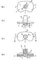
- a first sliding partner (1) is designed as a tibial component, a knee joint endoprosthesis.
- This tibial component consists essentially of a bearing plate (2), an elevation (3) and a fastening sleeve (4) for attachment of the first sliding partner (1) on a tibia, not shown, of a human leg, also not shown.
- the elevation (3) is annularly surrounded by a toothed rim (18) at a certain distance (17) from the pressure surface (7), which is fixedly connected to the surface of the elevation.
- a toothed rim (18) On the sprocket (18) are teeth (19), the star-shaped projecting from the surface of the elevation (3) outward.
- Both the attachment stub (4) and the elevation (3) are traversed by a bore (20) which, on the one hand, faces away from the elevation (3) in an end (21) facing away from the pressure surface (7) and, on the other hand, into a conical end portion (22). of the attachment piece (4) ends.
- the elevation (3) has on a the end (21) facing bottom (23) of the ring gear (18) a guide piece (x24) which projects into a receptacle adapted to him (25), the recess (8) at its farthest limited in the second sliding partner (5) protruding end (26). In this receptacle (25), the guide piece (24) and thus the entire second sliding partner (5) is guided.
- the recess (8) is bounded in the region of the bearing plate by an edge region which consists essentially of tooth contours (30) which delimit the depression (8). On this tooth contours introduced increase (3) in the recess (8) in the region of the distance (17).
- the second sliding partner (5) is guided with its recess (8) over the end (21) of the elevation (3). If the teeth (19) do not slide through the tooth-shaped recesses (28) immediately after placement of the second sliding partner (5), in the direction of the free space (29), the second sliding partner (5) is slightly pivoted, so that the Teeth (19) are enabled to slide through the tooth-shaped recesses (28) in the direction of the free space (29) therethrough.
- the tooth-shaped recesses (28) are largely adapted in their design to the teeth (19) of the ring gear (18).
- the second sliding partner (5) is slightly pivoted relative to the first sliding partner (1), so that now the teeth (19) no longer in alignment with the tooth-shaped recesses (28) but are prevented from leaving the free space (29) by flanks (31) extending between the individual tooth-shaped recesses (28) and serve as a guide for the teeth (19) ,
- the tooth-shaped recesses (28) have the same arrangement within the junction (27) of the recess (8) as the teeth (19) on the sprocket (18). This arrangement is characterized in that two teeth facing each other with respect to a center line of the elevation extend on a common center line. Likewise, two oppositely disposed tooth-shaped recesses (28) extend on a common center line. Finally, an equal number of teeth (19) or tooth-shaped recesses (28) are arranged over the circumference of both the elevation (3) and the depression (8).
- the tooth-shaped recesses (28) are shifted by an angle of 22.5 °, so that the teeth (19) with parallel boundary lines (11, 12, 13, 14, 15, 16) can not be moved through the tooth-shaped recesses (28), but are held by the flanks (31) in the free space (29).
- the ring gear (18) can be pivoted within the free space (29) by a total angle of 45 °, without the risk that the teeth (19) of the ring gear (18) through the tooth-shaped recesses (28) can slide through.
Landscapes
- Health & Medical Sciences (AREA)
- Orthopedic Medicine & Surgery (AREA)
- Physical Education & Sports Medicine (AREA)
- Cardiology (AREA)
- Oral & Maxillofacial Surgery (AREA)
- Transplantation (AREA)
- Engineering & Computer Science (AREA)
- Biomedical Technology (AREA)
- Heart & Thoracic Surgery (AREA)
- Vascular Medicine (AREA)
- Life Sciences & Earth Sciences (AREA)
- Animal Behavior & Ethology (AREA)
- General Health & Medical Sciences (AREA)
- Public Health (AREA)
- Veterinary Medicine (AREA)
- Prostheses (AREA)
Abstract
Claims (14)
- Endoprothèse d'articulation du genou, avec un composant fémoral et un composant tibial, qui sont montés à pivotement, l'un par rapport à l'autre, autour d'un axe, sachant que le composant tibial est doté d'un plateau de tibia avec deux partenaires de glissement (1, 5), l'un (1) des partenaires de glissement formant une plaque de support (2) et l'autre partenaire de glissement (5) étant réalisé sous la forme d'une pièce de glissement montée, sur la plaque de support (2), à pivotement autour d'un guidage, et sur laquelle un composant fémoral peut être monté à pivotement, sachant que le guidage est réalisé sous la forme d'une élévation (3), qui s'engage, en ajustage précis, dans une cavité (8), prévue dans l'autre partenaire de glissement (5), et est guidée dans celle-ci, caractérisée en ce qu'un verrouillage des partenaire de glissement (1, 5) est réalisé par l'intermédiaire d'une couronne dentée (18), qui s'étend autour de l'élévation (3), à laquelle elle est reliée, et qui est dotée d'éléments dentés (19) saillants, qui peuvent passer à travers des évidements (28) d'une zone marginale entourant la cavité (8), et qui s'engagent dans un espace libre (29) situé en aval, dans la direction d'introduction, permettant un mouvement de rotation de la couronne dentée (18), et en ce que, après un pivotement relatif des partenaires de glissement (1, 5), les éléments dentés (19) sont verrouillés dans une zone de recouvrement, située entre les évidements (28).
- Endoprothèse d'articulation du genou selon la revendication 1, caractérisée en ce que les évidements (28) présentent des sections transversales de conception similaire à celles des éléments dentés (19).
- Endoprothèse d'articulation du genou selon revendication 1 ou 2, caractérisée en ce que les évidements (28) sont répartis, sur la zone marginale, avec la même densité et le même espacement que les éléments dentés (19) sur la couronne dentée (18).
- Endoprothèse d'articulation du genou selon l'une des revendications 1 à 3, caractérisée en ce que les évidements (28), en forme de dents, font saillie dans l'espace libre (29), qui est doté d'une section transversale permettant de recevoir l'épaisseur et le diamètre de la couronne dentée (18).
- Endoprothèse d'articulation du genou selon l'une des revendications 1 à 4, caractérisée en ce que l'espace libre (29) est conçu sous la forme d'un espace annulaire, qui s'étend autour de la cavité (8).
- Endoprothèse d'articulation du genou selon l'une des revendications 1 à 5, caractérisée en ce que la zone marginale est dotée de contours dentés (30), qui limitent la cavité (8) dans la région de la plaque de support (2).
- Endoprothèse d'articulation du genou selon la revendication 6, caractérisée en ce que l'élévation (3) est guidée sur les contours dentés (30), dans une zone voisine du partenaire de glissement (1).
- Endoprothèse d'articulation du genou selon la revendication 7, caractérisée en ce que, entre la couronne dentée (18) et le partenaire de glissement (1) voisin d'elle, est prévue une zone d'écartement (17), dont la hauteur correspond à une épaisseur de paroi de la zone dentée, qui est montée, étroitement ajustée, exempte de jeu dans la plus grande mesure possible, dans la zone d'écartement (17).
- Endoprothèse d'articulation du genou selon l'une des revendications 1 à 8, caractérisée en ce que l'élévation (3) est dotée, sur un côté de la couronne dentée (18) éloigné de la zone d'écartement (17), d'une zone d'extrémité (21), qui est amenée dans une la zone la plus profonde de la cavité (8), au-delà de l'espace libre (29).
- Endoprothèse d'articulation du genou selon l'une des revendications 1 à 9, caractérisée en ce que les dents (19), sont disposées, par rapport aux évidements en forme de dents (28) de sorte que, dans une position de base des partenaires de glissement (1,5) emboîtés, le partenaire de glissement (5) ne puisse pas être arraché de la plaque de support (2).
- Endoprothèse d'articulation du genou selon la revendication 10, caractérisée en ce que, dans la position de base des partenaires de glissement (1, 5) une concavité (10), prévue, dans le partenaire de glissement (5) pour recevoir un fémur pivoté, s'étend parallèlement à une concavité (9) correspondante de la plaque de support (2).
- Endoprothèse d'articulation du genou selon l'une des revendications 1 à 11, caractérisée en ce que, chaque fois, deux dents (19), situées l'une en face de l'autre dans la couronne dentée (18), présentent des lignes médianes de même orientation.
- Endoprothèse d'articulation du genou selon la revendication 12, caractérisée en ce que les lignes médianes de deux dents (19) opposées forment avec les lignes médianes de deux évidements en forme de dents (28) opposés un angle de 20 ° à 40 ° environ, les concavités (9, 10) du partenaire de glissement (5), d'une part, et de la plaque de support (2), d'autre part, s'étendant parallèlement.
- Endoprothèse d'articulation du genou selon la revendication 13, caractérisée en ce que l'angle entre les lignes médianes de dents (19) situées l'une en face de l'autre et les lignes médianes d'évidements en forme de dents (28), situés à l'opposé l'un de l'autre, est de 22,5 °, les partenaires de glissement (1, 5) étant orientés de manière identique.
Applications Claiming Priority (3)
| Application Number | Priority Date | Filing Date | Title |
|---|---|---|---|
| DE10307889 | 2003-02-25 | ||
| DE2003107889 DE10307889A1 (de) | 2003-02-25 | 2003-02-25 | Kniegelenkendoprothese |
| PCT/DE2004/000347 WO2004075793A2 (fr) | 2003-02-25 | 2004-02-25 | Prothese d'articulation du genou |
Publications (2)
| Publication Number | Publication Date |
|---|---|
| EP1599154A2 EP1599154A2 (fr) | 2005-11-30 |
| EP1599154B1 true EP1599154B1 (fr) | 2012-06-06 |
Family
ID=32797721
Family Applications (1)
| Application Number | Title | Priority Date | Filing Date |
|---|---|---|---|
| EP04714266A Expired - Lifetime EP1599154B1 (fr) | 2003-02-25 | 2004-02-25 | Prothese d'articulation du genou |
Country Status (3)
| Country | Link |
|---|---|
| EP (1) | EP1599154B1 (fr) |
| DE (2) | DE10307889A1 (fr) |
| WO (1) | WO2004075793A2 (fr) |
Family Cites Families (4)
| Publication number | Priority date | Publication date | Assignee | Title |
|---|---|---|---|---|
| FR2726174B1 (fr) * | 1994-10-26 | 1997-04-04 | Cornic Michel | Prothese d'articulation du genou |
| GB2336317B (en) * | 1996-12-09 | 2001-02-14 | Jacques Afriat | Complete knee joint prosthesis |
| GB2345446B (en) * | 1999-01-08 | 2000-11-22 | Corin Medical Ltd | A knee prosthesis |
| FR2797392B1 (fr) * | 1999-07-05 | 2002-03-01 | Aesculap Sa | Prothese totale du genou comportant un insert mobile par rapport a la plaque tibiale et une butee |
-
2003
- 2003-02-25 DE DE2003107889 patent/DE10307889A1/de not_active Withdrawn
-
2004
- 2004-02-25 DE DE112004000793T patent/DE112004000793D2/de not_active Expired - Fee Related
- 2004-02-25 WO PCT/DE2004/000347 patent/WO2004075793A2/fr not_active Ceased
- 2004-02-25 EP EP04714266A patent/EP1599154B1/fr not_active Expired - Lifetime
Also Published As
| Publication number | Publication date |
|---|---|
| DE10307889A1 (de) | 2004-09-02 |
| WO2004075793A3 (fr) | 2004-12-23 |
| WO2004075793A2 (fr) | 2004-09-10 |
| DE112004000793D2 (de) | 2006-01-19 |
| EP1599154A2 (fr) | 2005-11-30 |
Similar Documents
| Publication | Publication Date | Title |
|---|---|---|
| DE60008808T2 (de) | Ellenbogenprothese | |
| DE69720803T2 (de) | Raspel zum bearbeiten eines markkanals eines knochens | |
| EP0174531B1 (fr) | Endoprothèse d'une articulation | |
| DE3601938C2 (fr) | ||
| EP2055270B1 (fr) | Outil de manipulation manuel pour un implant médical, implant médical et ensemble comprenant un outil de manipulation ainsi qu'un implant | |
| DE4319010C1 (de) | Beckenteilendoprothese | |
| EP1729673B1 (fr) | Prothese intervertebrale cervicale | |
| DE69832861T2 (de) | Gelenkprothesensystem mit einer in Längsrichtung verschlossenen drehbaren Komponente | |
| DE2404481C2 (de) | Ellbogengelenk-Endoprothese | |
| DE9017245U1 (de) | Prothetische Lagerungsvorrichtung | |
| DE8304914U1 (de) | Kugelförmiges kinematisches Gelenk | |
| EP0884032A1 (fr) | Système de fixation pour supports similaires à une coque | |
| DE9301107U1 (de) | Oberschenkelknochenkomponente zur Verwendung in einem Hüftgelenkersatz | |
| EP2699203B1 (fr) | Prothèse articulaire pourvue d'une charnière de flexion à axe d'écartement | |
| DE2252876A1 (de) | Kiefernorthopaedischer zahnspangenhalter | |
| EP2768438B1 (fr) | Système de liaison et système de prothèse | |
| EP1388309B1 (fr) | Articulation, particulièrement pour chaises longues | |
| DE69512953T2 (de) | Verbesserung an Knieprothesen | |
| DE2253904A1 (de) | Zahnaerztliches handstueck | |
| WO2014170446A1 (fr) | Fermeture | |
| EP2535020A1 (fr) | Prothèses articulaires rotatives dotées d'un palier nu | |
| EP1599154B1 (fr) | Prothese d'articulation du genou | |
| EP3552574A1 (fr) | Implant dentaire analogique | |
| EP1108403B1 (fr) | Jeu de pièces pour l'assemblage d'une prothèse de genou | |
| DE3935488A1 (de) | Kniegelenk-endoprothese |
Legal Events
| Date | Code | Title | Description |
|---|---|---|---|
| PUAI | Public reference made under article 153(3) epc to a published international application that has entered the european phase |
Free format text: ORIGINAL CODE: 0009012 |
|
| 17P | Request for examination filed |
Effective date: 20050728 |
|
| AK | Designated contracting states |
Kind code of ref document: A2 Designated state(s): AT BE BG CH CY CZ DE DK EE ES FI FR GB GR HU IE IT LI LU MC NL PT RO SE SI SK TR |
|
| AX | Request for extension of the european patent |
Extension state: AL LT LV MK |
|
| RAX | Requested extension states of the european patent have changed |
Extension state: AL Payment date: 20050728 Extension state: MK Payment date: 20050728 |
|
| 17Q | First examination report despatched |
Effective date: 20071218 |
|
| GRAP | Despatch of communication of intention to grant a patent |
Free format text: ORIGINAL CODE: EPIDOSNIGR1 |
|
| GRAS | Grant fee paid |
Free format text: ORIGINAL CODE: EPIDOSNIGR3 |
|
| GRAA | (expected) grant |
Free format text: ORIGINAL CODE: 0009210 |
|
| AK | Designated contracting states |
Kind code of ref document: B1 Designated state(s): AT BE BG CH CY CZ DE DK EE ES FI FR GB GR HU IE IT LI LU MC NL PT RO SE SI SK TR |
|
| AX | Request for extension of the european patent |
Extension state: AL MK |
|
| REG | Reference to a national code |
Ref country code: GB Ref legal event code: FG4D Free format text: NOT ENGLISH |
|
| REG | Reference to a national code |
Ref country code: CH Ref legal event code: EP Ref country code: AT Ref legal event code: REF Ref document number: 560642 Country of ref document: AT Kind code of ref document: T Effective date: 20120615 |
|
| REG | Reference to a national code |
Ref country code: IE Ref legal event code: FG4D Free format text: LANGUAGE OF EP DOCUMENT: GERMAN |
|
| REG | Reference to a national code |
Ref country code: DE Ref legal event code: R096 Ref document number: 502004013557 Country of ref document: DE Effective date: 20120802 |
|
| REG | Reference to a national code |
Ref country code: CH Ref legal event code: NV Representative=s name: ALDO ROEMPLER PATENTANWALT |
|
| REG | Reference to a national code |
Ref country code: NL Ref legal event code: VDEP Effective date: 20120606 |
|
| PG25 | Lapsed in a contracting state [announced via postgrant information from national office to epo] |
Ref country code: CY Free format text: LAPSE BECAUSE OF FAILURE TO SUBMIT A TRANSLATION OF THE DESCRIPTION OR TO PAY THE FEE WITHIN THE PRESCRIBED TIME-LIMIT Effective date: 20120606 Ref country code: FI Free format text: LAPSE BECAUSE OF FAILURE TO SUBMIT A TRANSLATION OF THE DESCRIPTION OR TO PAY THE FEE WITHIN THE PRESCRIBED TIME-LIMIT Effective date: 20120606 Ref country code: SE Free format text: LAPSE BECAUSE OF FAILURE TO SUBMIT A TRANSLATION OF THE DESCRIPTION OR TO PAY THE FEE WITHIN THE PRESCRIBED TIME-LIMIT Effective date: 20120606 |
|
| PG25 | Lapsed in a contracting state [announced via postgrant information from national office to epo] |
Ref country code: SI Free format text: LAPSE BECAUSE OF FAILURE TO SUBMIT A TRANSLATION OF THE DESCRIPTION OR TO PAY THE FEE WITHIN THE PRESCRIBED TIME-LIMIT Effective date: 20120606 Ref country code: GR Free format text: LAPSE BECAUSE OF FAILURE TO SUBMIT A TRANSLATION OF THE DESCRIPTION OR TO PAY THE FEE WITHIN THE PRESCRIBED TIME-LIMIT Effective date: 20120907 |
|
| PG25 | Lapsed in a contracting state [announced via postgrant information from national office to epo] |
Ref country code: EE Free format text: LAPSE BECAUSE OF FAILURE TO SUBMIT A TRANSLATION OF THE DESCRIPTION OR TO PAY THE FEE WITHIN THE PRESCRIBED TIME-LIMIT Effective date: 20120606 Ref country code: NL Free format text: LAPSE BECAUSE OF FAILURE TO SUBMIT A TRANSLATION OF THE DESCRIPTION OR TO PAY THE FEE WITHIN THE PRESCRIBED TIME-LIMIT Effective date: 20120606 Ref country code: RO Free format text: LAPSE BECAUSE OF FAILURE TO SUBMIT A TRANSLATION OF THE DESCRIPTION OR TO PAY THE FEE WITHIN THE PRESCRIBED TIME-LIMIT Effective date: 20120606 Ref country code: SK Free format text: LAPSE BECAUSE OF FAILURE TO SUBMIT A TRANSLATION OF THE DESCRIPTION OR TO PAY THE FEE WITHIN THE PRESCRIBED TIME-LIMIT Effective date: 20120606 Ref country code: CZ Free format text: LAPSE BECAUSE OF FAILURE TO SUBMIT A TRANSLATION OF THE DESCRIPTION OR TO PAY THE FEE WITHIN THE PRESCRIBED TIME-LIMIT Effective date: 20120606 |
|
| PG25 | Lapsed in a contracting state [announced via postgrant information from national office to epo] |
Ref country code: PT Free format text: LAPSE BECAUSE OF FAILURE TO SUBMIT A TRANSLATION OF THE DESCRIPTION OR TO PAY THE FEE WITHIN THE PRESCRIBED TIME-LIMIT Effective date: 20121008 |
|
| PLBE | No opposition filed within time limit |
Free format text: ORIGINAL CODE: 0009261 |
|
| STAA | Information on the status of an ep patent application or granted ep patent |
Free format text: STATUS: NO OPPOSITION FILED WITHIN TIME LIMIT |
|
| PG25 | Lapsed in a contracting state [announced via postgrant information from national office to epo] |
Ref country code: DK Free format text: LAPSE BECAUSE OF FAILURE TO SUBMIT A TRANSLATION OF THE DESCRIPTION OR TO PAY THE FEE WITHIN THE PRESCRIBED TIME-LIMIT Effective date: 20120606 Ref country code: ES Free format text: LAPSE BECAUSE OF FAILURE TO SUBMIT A TRANSLATION OF THE DESCRIPTION OR TO PAY THE FEE WITHIN THE PRESCRIBED TIME-LIMIT Effective date: 20120917 |
|
| PGFP | Annual fee paid to national office [announced via postgrant information from national office to epo] |
Ref country code: FR Payment date: 20130320 Year of fee payment: 10 |
|
| 26N | No opposition filed |
Effective date: 20130307 |
|
| REG | Reference to a national code |
Ref country code: DE Ref legal event code: R097 Ref document number: 502004013557 Country of ref document: DE Effective date: 20130307 |
|
| PG25 | Lapsed in a contracting state [announced via postgrant information from national office to epo] |
Ref country code: BG Free format text: LAPSE BECAUSE OF FAILURE TO SUBMIT A TRANSLATION OF THE DESCRIPTION OR TO PAY THE FEE WITHIN THE PRESCRIBED TIME-LIMIT Effective date: 20120906 |
|
| PGFP | Annual fee paid to national office [announced via postgrant information from national office to epo] |
Ref country code: CH Payment date: 20130411 Year of fee payment: 10 |
|
| BERE | Be: lapsed |
Owner name: MTM MEDIZINTECHNIK MAUK G.M.B.H. Effective date: 20130228 |
|
| PG25 | Lapsed in a contracting state [announced via postgrant information from national office to epo] |
Ref country code: MC Free format text: LAPSE BECAUSE OF NON-PAYMENT OF DUE FEES Effective date: 20130228 |
|
| GBPC | Gb: european patent ceased through non-payment of renewal fee |
Effective date: 20130225 |
|
| REG | Reference to a national code |
Ref country code: IE Ref legal event code: MM4A |
|
| PG25 | Lapsed in a contracting state [announced via postgrant information from national office to epo] |
Ref country code: IE Free format text: LAPSE BECAUSE OF NON-PAYMENT OF DUE FEES Effective date: 20130225 Ref country code: GB Free format text: LAPSE BECAUSE OF NON-PAYMENT OF DUE FEES Effective date: 20130225 Ref country code: BE Free format text: LAPSE BECAUSE OF NON-PAYMENT OF DUE FEES Effective date: 20130228 |
|
| REG | Reference to a national code |
Ref country code: CH Ref legal event code: PL |
|
| PG25 | Lapsed in a contracting state [announced via postgrant information from national office to epo] |
Ref country code: LI Free format text: LAPSE BECAUSE OF NON-PAYMENT OF DUE FEES Effective date: 20140228 Ref country code: CH Free format text: LAPSE BECAUSE OF NON-PAYMENT OF DUE FEES Effective date: 20140228 |
|
| REG | Reference to a national code |
Ref country code: DE Ref legal event code: R082 Ref document number: 502004013557 Country of ref document: DE Representative=s name: ELBPATENT - MARSCHALL & PARTNER PARTGMBB, DE |
|
| REG | Reference to a national code |
Ref country code: FR Ref legal event code: ST Effective date: 20141031 |
|
| PG25 | Lapsed in a contracting state [announced via postgrant information from national office to epo] |
Ref country code: FR Free format text: LAPSE BECAUSE OF NON-PAYMENT OF DUE FEES Effective date: 20140228 |
|
| PG25 | Lapsed in a contracting state [announced via postgrant information from national office to epo] |
Ref country code: TR Free format text: LAPSE BECAUSE OF FAILURE TO SUBMIT A TRANSLATION OF THE DESCRIPTION OR TO PAY THE FEE WITHIN THE PRESCRIBED TIME-LIMIT Effective date: 20120606 |
|
| PG25 | Lapsed in a contracting state [announced via postgrant information from national office to epo] |
Ref country code: LU Free format text: LAPSE BECAUSE OF NON-PAYMENT OF DUE FEES Effective date: 20130225 Ref country code: HU Free format text: LAPSE BECAUSE OF FAILURE TO SUBMIT A TRANSLATION OF THE DESCRIPTION OR TO PAY THE FEE WITHIN THE PRESCRIBED TIME-LIMIT; INVALID AB INITIO Effective date: 20040225 |
|
| PG25 | Lapsed in a contracting state [announced via postgrant information from national office to epo] |
Ref country code: IT Free format text: LAPSE BECAUSE OF NON-PAYMENT OF DUE FEES Effective date: 20140225 |
|
| PGFP | Annual fee paid to national office [announced via postgrant information from national office to epo] |
Ref country code: DE Payment date: 20220219 Year of fee payment: 19 Ref country code: AT Payment date: 20220224 Year of fee payment: 19 |
|
| REG | Reference to a national code |
Ref country code: DE Ref legal event code: R119 Ref document number: 502004013557 Country of ref document: DE |
|
| REG | Reference to a national code |
Ref country code: AT Ref legal event code: MM01 Ref document number: 560642 Country of ref document: AT Kind code of ref document: T Effective date: 20230225 |
|
| PG25 | Lapsed in a contracting state [announced via postgrant information from national office to epo] |
Ref country code: AT Free format text: LAPSE BECAUSE OF NON-PAYMENT OF DUE FEES Effective date: 20230225 |
|
| PG25 | Lapsed in a contracting state [announced via postgrant information from national office to epo] |
Ref country code: DE Free format text: LAPSE BECAUSE OF NON-PAYMENT OF DUE FEES Effective date: 20230901 |