EP1599131B1 - Vorrichtung zur messung der konzentration eines analyts in einer augenflüssigkeit - Google Patents
Vorrichtung zur messung der konzentration eines analyts in einer augenflüssigkeit Download PDFInfo
- Publication number
- EP1599131B1 EP1599131B1 EP04710848A EP04710848A EP1599131B1 EP 1599131 B1 EP1599131 B1 EP 1599131B1 EP 04710848 A EP04710848 A EP 04710848A EP 04710848 A EP04710848 A EP 04710848A EP 1599131 B1 EP1599131 B1 EP 1599131B1
- Authority
- EP
- European Patent Office
- Prior art keywords
- fluorescence
- eye
- photometer
- ocular
- optical path
- Prior art date
- Legal status (The legal status is an assumption and is not a legal conclusion. Google has not performed a legal analysis and makes no representation as to the accuracy of the status listed.)
- Expired - Lifetime
Links
- 239000012491 analyte Substances 0.000 title claims abstract description 64
- 239000012530 fluid Substances 0.000 title claims abstract description 26
- 238000005259 measurement Methods 0.000 claims abstract description 73
- WQZGKKKJIJFFOK-GASJEMHNSA-N Glucose Natural products OC[C@H]1OC(O)[C@H](O)[C@@H](O)[C@@H]1O WQZGKKKJIJFFOK-GASJEMHNSA-N 0.000 claims abstract description 55
- 239000008103 glucose Substances 0.000 claims abstract description 55
- 239000008280 blood Substances 0.000 claims abstract description 30
- 210000004369 blood Anatomy 0.000 claims abstract description 30
- 238000000034 method Methods 0.000 claims abstract description 12
- 230000003287 optical effect Effects 0.000 claims description 39
- 210000001747 pupil Anatomy 0.000 claims description 27
- 230000001678 irradiating effect Effects 0.000 claims description 18
- 210000004087 cornea Anatomy 0.000 claims description 8
- 238000012545 processing Methods 0.000 claims description 4
- 230000009977 dual effect Effects 0.000 abstract description 5
- 239000007850 fluorescent dye Substances 0.000 description 14
- 230000005284 excitation Effects 0.000 description 6
- NOESYZHRGYRDHS-UHFFFAOYSA-N insulin Chemical compound N1C(=O)C(NC(=O)C(CCC(N)=O)NC(=O)C(CCC(O)=O)NC(=O)C(C(C)C)NC(=O)C(NC(=O)CN)C(C)CC)CSSCC(C(NC(CO)C(=O)NC(CC(C)C)C(=O)NC(CC=2C=CC(O)=CC=2)C(=O)NC(CCC(N)=O)C(=O)NC(CC(C)C)C(=O)NC(CCC(O)=O)C(=O)NC(CC(N)=O)C(=O)NC(CC=2C=CC(O)=CC=2)C(=O)NC(CSSCC(NC(=O)C(C(C)C)NC(=O)C(CC(C)C)NC(=O)C(CC=2C=CC(O)=CC=2)NC(=O)C(CC(C)C)NC(=O)C(C)NC(=O)C(CCC(O)=O)NC(=O)C(C(C)C)NC(=O)C(CC(C)C)NC(=O)C(CC=2NC=NC=2)NC(=O)C(CO)NC(=O)CNC2=O)C(=O)NCC(=O)NC(CCC(O)=O)C(=O)NC(CCCNC(N)=N)C(=O)NCC(=O)NC(CC=3C=CC=CC=3)C(=O)NC(CC=3C=CC=CC=3)C(=O)NC(CC=3C=CC(O)=CC=3)C(=O)NC(C(C)O)C(=O)N3C(CCC3)C(=O)NC(CCCCN)C(=O)NC(C)C(O)=O)C(=O)NC(CC(N)=O)C(O)=O)=O)NC(=O)C(C(C)CC)NC(=O)C(CO)NC(=O)C(C(C)O)NC(=O)C1CSSCC2NC(=O)C(CC(C)C)NC(=O)C(NC(=O)C(CCC(N)=O)NC(=O)C(CC(N)=O)NC(=O)C(NC(=O)C(N)CC=1C=CC=CC=1)C(C)C)CC1=CN=CN1 NOESYZHRGYRDHS-UHFFFAOYSA-N 0.000 description 6
- 239000000523 sample Substances 0.000 description 6
- 230000002596 correlated effect Effects 0.000 description 5
- GNBHRKFJIUUOQI-UHFFFAOYSA-N fluorescein Chemical compound O1C(=O)C2=CC=CC=C2C21C1=CC=C(O)C=C1OC1=CC(O)=CC=C21 GNBHRKFJIUUOQI-UHFFFAOYSA-N 0.000 description 5
- 125000002791 glucosyl group Chemical group C1([C@H](O)[C@@H](O)[C@H](O)[C@H](O1)CO)* 0.000 description 5
- 101710203008 D-galactose-binding periplasmic protein Proteins 0.000 description 4
- 238000011088 calibration curve Methods 0.000 description 4
- 239000000975 dye Substances 0.000 description 4
- PYWVYCXTNDRMGF-UHFFFAOYSA-N rhodamine B Chemical compound [Cl-].C=12C=CC(=[N+](CC)CC)C=C2OC2=CC(N(CC)CC)=CC=C2C=1C1=CC=CC=C1C(O)=O PYWVYCXTNDRMGF-UHFFFAOYSA-N 0.000 description 4
- 108010062580 Concanavalin A Proteins 0.000 description 3
- 229920002307 Dextran Polymers 0.000 description 3
- 102000004877 Insulin Human genes 0.000 description 3
- 108090001061 Insulin Proteins 0.000 description 3
- 206010012601 diabetes mellitus Diseases 0.000 description 3
- 238000005516 engineering process Methods 0.000 description 3
- 229940125396 insulin Drugs 0.000 description 3
- 238000012544 monitoring process Methods 0.000 description 3
- 235000018102 proteins Nutrition 0.000 description 3
- 102000004169 proteins and genes Human genes 0.000 description 3
- 108090000623 proteins and genes Proteins 0.000 description 3
- 102000005548 Hexokinase Human genes 0.000 description 2
- 108700040460 Hexokinases Proteins 0.000 description 2
- 241000124008 Mammalia Species 0.000 description 2
- ZYGHJZDHTFUPRJ-UHFFFAOYSA-N coumarin Chemical compound C1=CC=C2OC(=O)C=CC2=C1 ZYGHJZDHTFUPRJ-UHFFFAOYSA-N 0.000 description 2
- 238000002866 fluorescence resonance energy transfer Methods 0.000 description 2
- 108010070004 glucose receptor Proteins 0.000 description 2
- 238000001802 infusion Methods 0.000 description 2
- 230000035945 sensitivity Effects 0.000 description 2
- 239000012086 standard solution Substances 0.000 description 2
- ZCYVEMRRCGMTRW-UHFFFAOYSA-N 7553-56-2 Chemical compound [I] ZCYVEMRRCGMTRW-UHFFFAOYSA-N 0.000 description 1
- HRPVXLWXLXDGHG-UHFFFAOYSA-N Acrylamide Chemical group NC(=O)C=C HRPVXLWXLXDGHG-UHFFFAOYSA-N 0.000 description 1
- 208000002177 Cataract Diseases 0.000 description 1
- 241000588724 Escherichia coli Species 0.000 description 1
- 102000030595 Glucokinase Human genes 0.000 description 1
- 108010021582 Glucokinase Proteins 0.000 description 1
- 241001465754 Metazoa Species 0.000 description 1
- 210000001742 aqueous humor Anatomy 0.000 description 1
- 230000001580 bacterial effect Effects 0.000 description 1
- 230000005540 biological transmission Effects 0.000 description 1
- ZADPBFCGQRWHPN-UHFFFAOYSA-N boronic acid Chemical compound OBO ZADPBFCGQRWHPN-UHFFFAOYSA-N 0.000 description 1
- SXDBWCPKPHAZSM-UHFFFAOYSA-M bromate Inorganic materials [O-]Br(=O)=O SXDBWCPKPHAZSM-UHFFFAOYSA-M 0.000 description 1
- SXDBWCPKPHAZSM-UHFFFAOYSA-N bromic acid Chemical compound OBr(=O)=O SXDBWCPKPHAZSM-UHFFFAOYSA-N 0.000 description 1
- 150000001720 carbohydrates Chemical class 0.000 description 1
- 235000014633 carbohydrates Nutrition 0.000 description 1
- 230000001010 compromised effect Effects 0.000 description 1
- 230000000875 corresponding effect Effects 0.000 description 1
- 229960000956 coumarin Drugs 0.000 description 1
- 235000001671 coumarin Nutrition 0.000 description 1
- 125000000151 cysteine group Chemical group N[C@@H](CS)C(=O)* 0.000 description 1
- 125000001295 dansyl group Chemical group [H]C1=C([H])C(N(C([H])([H])[H])C([H])([H])[H])=C2C([H])=C([H])C([H])=C(C2=C1[H])S(*)(=O)=O 0.000 description 1
- 230000007423 decrease Effects 0.000 description 1
- 230000001419 dependent effect Effects 0.000 description 1
- 230000003292 diminished effect Effects 0.000 description 1
- 208000037265 diseases, disorders, signs and symptoms Diseases 0.000 description 1
- 229940079593 drug Drugs 0.000 description 1
- 239000003814 drug Substances 0.000 description 1
- 230000000694 effects Effects 0.000 description 1
- 238000005401 electroluminescence Methods 0.000 description 1
- 210000003722 extracellular fluid Anatomy 0.000 description 1
- 230000004424 eye movement Effects 0.000 description 1
- 229960002143 fluorescein Drugs 0.000 description 1
- 230000037406 food intake Effects 0.000 description 1
- 235000012631 food intake Nutrition 0.000 description 1
- 239000012634 fragment Substances 0.000 description 1
- 102000036202 glucose binding proteins Human genes 0.000 description 1
- 108091011004 glucose binding proteins Proteins 0.000 description 1
- 229940088597 hormone Drugs 0.000 description 1
- 239000005556 hormone Substances 0.000 description 1
- 238000005286 illumination Methods 0.000 description 1
- 239000007943 implant Substances 0.000 description 1
- 238000012623 in vivo measurement Methods 0.000 description 1
- 229960004657 indocyanine green Drugs 0.000 description 1
- MOFVSTNWEDAEEK-UHFFFAOYSA-M indocyanine green Chemical compound [Na+].[O-]S(=O)(=O)CCCCN1C2=CC=C3C=CC=CC3=C2C(C)(C)C1=CC=CC=CC=CC1=[N+](CCCCS([O-])(=O)=O)C2=CC=C(C=CC=C3)C3=C2C1(C)C MOFVSTNWEDAEEK-UHFFFAOYSA-M 0.000 description 1
- 208000015181 infectious disease Diseases 0.000 description 1
- 238000002347 injection Methods 0.000 description 1
- 239000007924 injection Substances 0.000 description 1
- 229910052740 iodine Inorganic materials 0.000 description 1
- 239000011630 iodine Substances 0.000 description 1
- 239000004973 liquid crystal related substance Substances 0.000 description 1
- 229940107698 malachite green Drugs 0.000 description 1
- FDZZZRQASAIRJF-UHFFFAOYSA-M malachite green Chemical compound [Cl-].C1=CC(N(C)C)=CC=C1C(C=1C=CC=CC=1)=C1C=CC(=[N+](C)C)C=C1 FDZZZRQASAIRJF-UHFFFAOYSA-M 0.000 description 1
- 230000002441 reversible effect Effects 0.000 description 1
- 210000003786 sclera Anatomy 0.000 description 1
- 239000002904 solvent Substances 0.000 description 1
- 230000003068 static effect Effects 0.000 description 1
- 239000000126 substance Substances 0.000 description 1
- 210000001138 tear Anatomy 0.000 description 1
- 238000012360 testing method Methods 0.000 description 1
- 210000001519 tissue Anatomy 0.000 description 1
- 230000004304 visual acuity Effects 0.000 description 1
Images


Classifications
-
- A—HUMAN NECESSITIES
- A61—MEDICAL OR VETERINARY SCIENCE; HYGIENE
- A61B—DIAGNOSIS; SURGERY; IDENTIFICATION
- A61B5/00—Measuring for diagnostic purposes; Identification of persons
- A61B5/145—Measuring characteristics of blood in vivo, e.g. gas concentration or pH-value ; Measuring characteristics of body fluids or tissues, e.g. interstitial fluid or cerebral tissue
- A61B5/1455—Measuring characteristics of blood in vivo, e.g. gas concentration or pH-value ; Measuring characteristics of body fluids or tissues, e.g. interstitial fluid or cerebral tissue using optical sensors, e.g. spectral photometrical oximeters
-
- A—HUMAN NECESSITIES
- A61—MEDICAL OR VETERINARY SCIENCE; HYGIENE
- A61B—DIAGNOSIS; SURGERY; IDENTIFICATION
- A61B5/00—Measuring for diagnostic purposes; Identification of persons
- A61B5/145—Measuring characteristics of blood in vivo, e.g. gas concentration or pH-value ; Measuring characteristics of body fluids or tissues, e.g. interstitial fluid or cerebral tissue
- A61B5/14532—Measuring characteristics of blood in vivo, e.g. gas concentration or pH-value ; Measuring characteristics of body fluids or tissues, e.g. interstitial fluid or cerebral tissue for measuring glucose, e.g. by tissue impedance measurement
-
- A—HUMAN NECESSITIES
- A61—MEDICAL OR VETERINARY SCIENCE; HYGIENE
- A61B—DIAGNOSIS; SURGERY; IDENTIFICATION
- A61B5/00—Measuring for diagnostic purposes; Identification of persons
- A61B5/68—Arrangements of detecting, measuring or recording means, e.g. sensors, in relation to patient
- A61B5/6801—Arrangements of detecting, measuring or recording means, e.g. sensors, in relation to patient specially adapted to be attached to or worn on the body surface
- A61B5/6813—Specially adapted to be attached to a specific body part
- A61B5/6814—Head
- A61B5/6821—Eye
Definitions
- the present invention relates to a hand-held fluorescence photometer and methods for measuring an analyte level, preferably a blood glucose level, from an ocular fluid.
- the photometer is capable of self defining the correct position with respect to the eye for measuring. As the apparatus is properly positioned the analyte measurement automatically takes place.
- WO-A-01/13783 Various non-invasive or minimally invasive technologies to measure blood glucose levels from an ocular fluid such as tears, aqueous humor, or interstitial fluid have been described.
- Relevant to the present invention is the ocular sensor for glucose disclosed in WO-A-01/13783 .
- the ocular sensor described by WO-A-01/13783 is an ophthalmic lens comprising a glucose receptor labeled with a first fluorescent label and a glucose, competitor labeled with a second fluorescent label.
- the two fluorescent labels are selected in a way that while the competitor is bound to the receptor, the fluorescence of the second fluorescent label is quenched via a fluorescence resonance energy transfer.
- the amount of the fluorescently labeled competitor that is displaced from the receptor by glucose is measured and provides a means of determining the glucose concentration in an ocular fluid.
- This measurement can, in turn, be manipulated to provide a measurement of blood glucose level.
- the first fluorescent label could serve as an internal standard in the determination of glucose concentration in an ocular fluid and thereby could enhance the accuracy of determination of glucose concentration in an ocular fluid.
- WO-A-02/087429 discloses a fluorescence photometer for measuring blood glucose level from an ocular fluid which is capable of measuring simultaneously two fluorescence intensities at two different wavelengths and that could therefore benefit from the measurement system disclosed in WO-A-01/13783 .
- ocular analyte concentration or "ocular analyte level” as used herein refers to an analyte concentration in an ocular fluid.
- blood analyte concentration or level or "ocular analyte level” as used herein refers to an analyte concentration in the blood stream of a person.
- the present invention in one aspect, provides a hand-held fluorescence photometer for measuring an analyte level, preferably a blood glucose level from an ocular fluid based on a dual beam measuring system having preferably confocal optical paths.
- the fluorescence photometer of the invention comprises:
- the proper positioning of the apparatus is achieved by measuring the pupil fluorescence intensity, also addressed as first fluorescence intensity, by means of the pilot beam optical path.
- the intensity of the pupil fluorescence is in fact correlated to the distance of the measurement tool from the eye. Only when the distance of the measurement tool from the eye is such that the measurement beam irradiates the iris, the actual measurement starts.
- the iris has an auto fluorescence which is about 100 times lower than the fluorescence of the pupil. Therefore in order to achieve a high signal/noise ratio it is advantageous to direct the measurement beam to hit the iris of the patient's eye. Whenever the photometer is misplaced the measurement beam automatically stops.
- the small dimensions together with the high accuracy achieved by the photometer of the present invention allows for the first time to focus two beams at the same time in a patient's eye and therefore to benefit from a dual beam measurement system.
- the photometer further includes a calculating means or a processing circuit for determining based on the measured fluorescence intensities:
- this invention provides a method for measuring an analyte level, preferably blood glucose level from an ocular fluid.
- a method for measuring an analyte level preferably blood glucose level from an ocular fluid.
- Such a method comprises:
- the geometry of said fluorescence photometer is such that when the fluorescence photometer is in use, the pilot beam is positioned to a fixed angle and distance from the measurement beam wherein said angle is greater than 0 degrees and smaller than 90 degrees; and the measurement beam is irradiated onto the iris of the patient's eye.
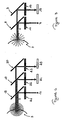
- a pilot beam 1 having a well defined wavelength number irradiates the pupil 2 of a patient's eye 3 wearing an ocular analyte sensor (not shown). Such irradiation causes the pupil 2 to emit a first fluorescence 11 of a defined wavelength range which travels along a first optical path and is measured by means of a detector. The measured fluorescence intensity range is then correlated to the distance between the fluorescence photometer and the eye.
- the geometry of the present fluorescence photometer is such that the pilot beam 1 and a measurement 5 beam which is used for the actual analyte measurement are positioned to a fixed angle ⁇ with respect to the patient's eye 3 as shown in Figure 2.
- an internal circuit (not shown) sends a signal to start the actual analyte measurement. Only then, the measurement beam 5 irradiates the iris 6 of the patient's eye 3 .
- the ocular analyte sensor Upon irradiation, the ocular analyte sensor emits a total fluorescence 55 having at least a second wavelength band which travels along a second optical path and is measured by means of a detector. The measured fluorescence intensity is then correlated to the analyte concentration in the blood of the patient.
- the angle ⁇ is chosen in such a way that the measurement beam irradiates the surface eye in the iris 6 with the limits set by the pupil 2 and the sclera depending on the optics of the photometer and on the optimal distance of measurement.
- the angle ⁇ is greater than 0 degrees and smaller than 90 degrees.
- the angle ⁇ is between 20 and 50 degrees and more preferably is between 30 and 40 degrees.
- a preferred measurement distance is between 100 mm and 1 mm, more preferably is between 5 and 30 mm.
- the pilot beam 1 also causes the emission of fluorescence of the ocular sensor but such a fluorescence can be neglected compared to the fluorescence emitted by the pupil 2 .
- the measurement beam 5 causes the iris 6 to emit a fluorescence however such a fluorescence may be neglected compared to the fluorescence generated by the ocular glucose sensor.
- the pupil itself 2 becomes smaller making the measurement system independent from the pupil 2 versus iris 6 dimensions which may vary from patient to patient and on illumination conditions.
- FIG 3 describes schematically the optical path with respect to the eye of the pilot beam 1 (also shown in Figure 5) in the fluorescence photometer of a preferred embodiment.
- a fluorescence photometer comprises a first light emitting diode 7 serving as irradiating means, dichroic mirrors 8, 9 with the dual function of reflecting and splitting the beam, filters 10, 12 and a first detecting means 13 .
- the first light emitting diode 7 emits excitation light of a defined wavelength range which travels trough filter 10 to obtain a monochromatic beam or pilot beam.
- Dichroic mirror 8 directs the measurement beam towards the patient's eye 3 .
- the pilot beam 1 Before hitting the pupil 2 of the patient's eye 3 the pilot beam 1 is collimated and property focused by means of standard lenses (not shown).
- Such irradiation in the eye 3 causes the pupil 2 to emit a characteristic fluorescence also referred as first fluorescence which travels back to the dichroic mirror 8 . Then, the dichroic mirror 8 blocks the reflected excitation light and allows the pupil fluorescence, which has a higher wavelength band to proceed further on its optical path.
- the dichroic mirror 9 directs the pupil fluorescence to filter 12 which makes sure that only the pupil fluorescence having a well defined wavelength range reaches the detector 13 and is measured.
- Figure 4 shows schematically the optical path with respect to the patient's eye 3 of the measurement beam 5 in the fluorescence photometer in a preferred embodiment of the present invention.
- an ocular glucose sensor which emits a total fluorescence having a second fluorescence and a third fluorescence at well defined wavelength numbers is used.
- the apparatus comprises at least a second light emitting diode 17 serving as irradiating means, dichroic mirrors 18, 19 with the dual function of reflecting and splitting the beam, a simple mirror 20 , filters 21, 22, 23 , a second and a third detecting means 24, 25 .
- the second light emitting diode 17 emits excitation light of a defined wavelength range which travels trough filter 21 to obtain a monochromatic beam or measurement beam 5 .
- the dichroic mirror 18 directs the measurement beam 5 towards the patient's eye 3 .
- the measurement beam 5 is collimated and properly focused by means of standard lenses (not shown).
- Such irradiation of the iris 6 causes the glucose ocular sensor to emit a total fluorescence which travels back to the dichroic mirror 18 .
- the dichroic mirror 18 blocks the reflected excitation light and allows the total fluorescence which has higher wavelength bands to proceed further on its optical path.
- the dichroic mirror 19 splits the total fluorescence into a second fluorescence having a second wavelength band and a third fluorescence having a third wavelength band.
- the second fluorescence which has a lower wavelength band is then deviated to filter 22 and the third fluorescence is allowed to pass trough.
- Filter 22 allows only the second fluorescence with a well defined wavelength number to reach the second detector 24 .
- the third fluorescence band on its optical path encounters mirror 20 which directs it to the third detector 25 after being filtered out.
- the third fluorescence having a well defined wavelength number is then measured.
- the measurement beam optical path comprises more than one light source.
- the measurement beam optical path further comprises a third light emitting diode 27 , an additional dichroic mirror 28 and an additional filter 29 .
- the excitation light coming from the second light emitting diode 17 is used to excite especially the second fluorescence of the ocular sensor and the third light emitting diode 27 is used to excite especially the third fluorescence of the ocular sensor.
- dichroic mirror 28 blocks lower wavelength number and allows the higher wavelength number band to continue in the optical path.
- the photometer of the present invention further comprises one or more additional irradiating means for providing the pilot beam.
- the light sources then are preferably used in sequence during the positioning of the apparatus and the measurement.
- Figure 5 also shows a possible combination of the preferred optical path of the pilot beam 1 and of the measurement beam 5 in the fluorescence photometer of the present invention.
- the photometer preferably further includes a calculating means or a processing circuit (not shown) for determining based on the measured fluorescence intensities:
- the ocular sensor emits a fluorescence with only one wavelength band or in the case in which the ocular sensor emits a fluorescence with more than two wavelength bands.
- the number of dichroic mirrors in the measurement beam optical path may be diminished or increased.
- the number of light source may be on convenience increased.
- the analyte to be measured may be glucose as well as any other substance present in an ocular fluid such as hormones.
- the fluorescence photometer then has to be modified accordingly within the concept of the invention.
- both the dichroic mirror and filter positions with respect to the measurement and/or pilot beam optical path have to be optimized depending on the ocular analyte sensor and on the optics employed.
- the light sources are preferably Surface Mounted Device light emitting diodes having a defined wavelength range which are characterized by uniform light distribution and smaller power compared to standard light emitting diodes.
- any other kind of light emitting diodes, lasers or electroluminescence light sources could be employed.
- Dichroic mirrors block lower wavelength number and allow the higher wavelength number band to continue in the optical path. Their positioning with respect to the beams optical path as well as the filter positioning as to be optimized for every specific case measurement system.
- a surface mounted light emitting diode having an excitation light of 465 nm is used.
- the dichroic mirrors and the filters preferably have an angle of 45 and 90 degree respectively with respect to the pilot beam and measurement beam optical paths.
- the angle ⁇ between the pilot beam and the measurement beam in this preferred embodiment is 35 degrees.
- the photometer to make these measurements could take several configurations such as a moderate sized laboratory instrument or a small hand-held, portable, self contained unit suitable for the user to carry easily in a pocket or purse.
- the length of the fluorescence photometer is preferably between 3 and 20 cm, preferably between 5 and 15 cm and most preferably between 7 and 10 cm.
- the thickness is, for example, between 1 and 7 cm, preferably, between 2 and 4 cm.
- the instrument is used by looking into an optical window while holding the apparatus in front of the eye to a distance which is determined by the pilot beam 1 when the instrument is in use.
- an integral cover is provided to protect the optical elements.
- a display preferably using liquid crystals or light emitting diodes, which provides readout of the analyte value and instrument diagnostic including battery status is position in the internal surface of such a cover 31.
- the display is positioned on an external cover.
- a battery compartment is provided at the opposite end of the instrument.
- the pilot beam as well as measurement beam preferably have confocal optics.
- the pilot beam has a sharp focus.
- the measurement beam preferably has a more diffuse focus.
- An initial calibration process may be required for instance to account for differences in natural fluorescence of patients and for the specific characteristics of the ocular analyte sensor employed.
- a standardization may be done measuring the fluorescence intensity of a reference dye, which may have been embedded in the ocular analyte sensor, wherein such a dye is non-active with respect to the analyte.
- the ocular sensor comprises more than one fluorescent label, one could serve as an internal standard in the determination of the analyte concentration in an ocular fluid.
- An additional calibration may be done by measuring one fluorescent label while exiting another one. This would compensate for the variation (if any) in intensity of the pilot beam when the distance from the eye is slightly varied (order of micrometers).
- a calibration table or calibration curve as used herein means a table or curve containing in correlated form fluorescence intensity or fluorescence intensity ratios and their corresponding actual analyte concentrations.
- a calibration table or calibration curve can for instance be obtained once a day or just before testing of blood glucose levels by using at least three standard solutions with known glucose concentrations over a glucose concentration range from 30 to 500 mg/L.
- the obtained calibration table or curve is preferably stored in the apparatus which is used subsequently to determine blood glucose concentration.
- the correlation between blood glucose concentration and ocular glucose concentration can be determined by methods well known in the art. See, for example, March et al., Diabetes Care 5, 259-65, 1982 . It is preferred to store such correlation between blood glucose concentration and ocular glucose concentration in the apparatus of the present invention so that the measurement of ocular glucose concentration can be converted into a value of blood glucose concentration.
- Standard solutions can be provided to a user in calibration kits. They are stored in containers, preferably in a rectangular container having a plurality of separate compartments. The kits can also include calibration instruction.
- the measured blood glucose concentration value may be transmitted to another piece of equipment via wire or cable, or wirelessly, such as via radio frequency or infrared transmission.
- a telemetry signal can be transmitted to an infusion pump, which can provide insulin to maintain suitable levels of glucose in the body.
- the telemetry signal may be analog or digital.
- Infusion pumps are well known in the art for delivering a selected medication to a patient including humans and other animals in accordance with an administration schedule which can be pre-selected or, in some instances, preprogrammed.
- Pumps for use in this invention can be worn externally or can be directly implanted into the body of a mammal, including a human, to deliver a specific insulin to the mammal in controlled doses over an extended period of time.
- Such pumps are well known and are described, for example, in U.S. Patents 5,957,890 , 4,923,375 , 4,573,994 , and 3,731,681 .
- this invention provides a method for measuring an analyte level, preferably a blood glucose level from an ocular fluid.
- an ocular analyte sensor in contact with the ocular fluid is provided;
- the photometer is used by looking into an optical window while holding the apparatus in front of the eye.
- the pilot beam is irradiated into the pupil of the patient's eye and the pupil fluorescence is measured.
- the measurement beam is irradiated onto the patient's eye, preferably onto the iris to excite the ocular analyte sensor.
- said ocular analyte sensor emits a fluorescence having at least one wavelength band.
- the detected fluorescence intensity emitted by the sensor is then correlated to the analyte ocular and/or blood concentration.
- a suitable ocular sensor is for example an ophthalmic lens comprising an analyte receptor labeled with a first fluorescent label and an analyte competitor labeled with a second fluorescent label.
- the two fluorescent labels are selected in a way that while the competitor is bound to the receptor, the fluorescence of one of two fluorescent labels is quenched via a fluorescence resonance energy transfer by the other fluorescent label.
- the amount of the fluorescently labeled competitor that is displaced from the receptor by the analyte is measured and provides a means of determining the analyte concentration in an ocular fluid.
- Fluorescent labels such as fluorescein, indocyanine green, malachite green, and rhodamine, which are quenched when the competitor moiety is bound but are unquenched when the competitor moiety is not bound, are preferred for use as quenchable fluorescent label in the ocular glucose sensor.
- a particularly preferred combination of fluorescent labels is the combination of fluorescein (donor) and rhodamine (acceptor).
- the sensitivity of the ocular glucose sensor can be controlled by altering the concentration of the quenchable fluorescent label. Increasing the concentration of the quenchable fluorescent label in the ocular glucose sensor increases the range of fluorescence intensity and thereby increases the sensitivity of resulting measurements.
- the glucose receptor moiety comprises one or more binding site for glucose.
- the binding site also binds a moiety that competes with glucose for binding and is therefore referred to herein as a "glucose/competitor moiety binding site". Binding of both the competitor moiety and glucose to the glucose/competitor moiety binding site is reversible.
- the receptor moiety can be, for example, antibodies, boronic acid, a genetically engineered bacterial fluoriprotein, or preferably concanavalin A ( Mansouri & Schultz, Bio/Tech 2:385 (1984 )).
- suitable competitors to glucose for binding to concanavalin A are a polymeric carbohydrate, in particular dextran, or a glycoconjugate as described in US 5,342,789 .
- a particular preferred receptor competitor system is a system of a labeled concanavalin A and a labeled dextran, especially rhodamine-concanavalin A and fluorescein dextran.
- a suitable ocular analyte sensor may be an ophthalmic lens comprising a protein sensing molecule capable of binding analyte and having the property upon irradiation of emitting a fluorescence light having at least a fluorescence band that changes in intensity or decay time in a concentration-dependent manner when said molecule is bound to the analyte.
- the analyte is glucose
- the protein is an E. Coli glucose binding protein GGBP or functionally equivalent fragments thereof. Proteins other then GGBP may be used, for example, hexokinase, glucokinase, or mutants of hexokinase or mutants of GGBP.
- the sensing molecule may be labeled with one or more detectable labels like solvent sensitive probes such as dansyl probes, anilinonapthalene probes, deproxyl probes and similar probes which are sensitive to the polarity of the local environment.
- Other useful probes include donor-acceptor pairs such us fluorescein to rhodamine, coumarin to fluorescein or rhodamine.
- Still another class of useful label pairs include fluorophore-quencher pairs such as acrylamide groups, iodine and bromate etc in which the second group is a quencher which decreases the fluorescence intensity of the fluorescent group.
- a suitable ocular analyte sensor may in addition comprise a reference dye, e.g. for standardization or calibration purposes, which upon irradiation emits a characteristic fluorescence, wherein such a dye is non-active with respct to the analyte.
- a reference dye e.g. for standardization or calibration purposes, which upon irradiation emits a characteristic fluorescence, wherein such a dye is non-active with respct to the analyte.
- An ophthalmic lens is, for example, a removable lens, such as a contact lens, or a permanently implanted lens, such as an intraocular lens, a subconjunctival lens, or an intracorneal lens.
- Permanently implanted lenses are particularly well-suited for use in individuals who have compromised ocular function (e.g., cataracts) and also diabetic disease.
- Ophthalmic lenses can be corrective lenses or can be constructed so that they do not affect visual acuity.
- Contact lenses optionally can comprise a tint and are preferably disposable, which reduces the risk of infection for the user.
- the term "ophthalmic lens" may also refer to a shunt or implant that may rest in the subconjunctival part of the eye.
- Ophthalmic lenses according to embodiments of the invention can be worn chronically to provide repeated measurements or can be worn for a single measurement. Both qualitative and quantitative measurements can be performed.
Landscapes
- Health & Medical Sciences (AREA)
- Life Sciences & Earth Sciences (AREA)
- Physics & Mathematics (AREA)
- Medical Informatics (AREA)
- Surgery (AREA)
- Biophysics (AREA)
- Pathology (AREA)
- Engineering & Computer Science (AREA)
- Biomedical Technology (AREA)
- Heart & Thoracic Surgery (AREA)
- Veterinary Medicine (AREA)
- Molecular Biology (AREA)
- Public Health (AREA)
- Animal Behavior & Ethology (AREA)
- General Health & Medical Sciences (AREA)
- Optics & Photonics (AREA)
- Emergency Medicine (AREA)
- Spectroscopy & Molecular Physics (AREA)
- Ophthalmology & Optometry (AREA)
- Investigating, Analyzing Materials By Fluorescence Or Luminescence (AREA)
- Measurement Of The Respiration, Hearing Ability, Form, And Blood Characteristics Of Living Organisms (AREA)
- Eye Examination Apparatus (AREA)
- Investigating Or Analysing Biological Materials (AREA)
Claims (12)
- Tragbares Fluoreszenzphotometer zum Messen eines Analytlevels von einer Augenflüssigkeit, umfassend:a) mindestens ein erstes Bestrahlungsmittel zum Bereitstellen eines Pilotstrahles im Betrieb, wobei der Pilotstrahl von außerhalb der Cornea des Auges auf das Auge eines Benutzers eingestrahlt wird, um die Pupillen-Fluoreszenz oder erste Fluoreszenz anzuregen, wobei sich die Pupillen-Fluoreszenz entlang eines ersten optischen Weges ausbreitet;b) ein erstes Detektormittel, welches auf dem ersten optischem Weg angeordnet ist, um die Intensität der Pupillen-Fluoreszenz innerhalb des vorgegebenen Wellenlängenbereichs zu detektieren;c) ein zweites Bestrahlungsmittel zum Bereitstellen eines Messstrahles im Betrieb, wobei der Messstrahl von außerhalb der Cornea des Auges auf das Auge eines Benutzers eingestrahlt wird, um einen okularen Analytsensor anzuregen, wobei der okulare Analytsensor in Kontakt steht mit einer Augenflüssigkeit und bei Bestrahlung mit dem Bestrahlungsmittel eine Gesamtfluoreszenz emittiert, welche mindestens ein zweites Fluoreszenzwellenlängenband aufweist, wobei sich die zweite Fluoreszenz entlang eines zweiten optischen Weges ausbreitet;d) ein zweites Detektormittel, welches auf dem zweiten optischen Weg angeordnet ist, um die Intensität der zweiten Fluoreszenz bei der vorgegebenen Wellenlänge zu detektieren;wobei, wenn das Fluoreszenzphotometer im Betrieb ist, der Pilotstrahl in einem festen Winkel und in einer Distanz von dem Messstrahl positioniert ist, wobei der Winkel größer ist als 0 Grad und kleiner ist als 90 Grad.
- Fluoreszenzphotometer gemäß Anspruch 1, wobei der Messstrahl auf die Iris des Auges des Patienten eingestrahlt wird.
- Fluoreszenzphotometer gemäß Anspruch 1 oder 2, wobei der Pilotstrahl sowie der Messstrahl konfokale optische Wege aufweisen.
- Fluoreszenzphotometer gemäß einem der Ansprüche 1 bis 3, wobei der Analyt Blutglukose ist.
- Fluoreszenzphotometer gemäß einem der vorhergehenden Ansprüche, wobei, wenn das Fluoreszenzphotometer in Betrieb ist, der okulare Analytsensor bei Bestrahlung mit dem Bestrahlungsmittel eine Gesamtfluoreszenz emittiert, die den zweiten und den dritten Wellenlängenbereich aufweist, und wobei das Fluoreszenzphotometer weiterhin aufweist:e) einen optischen Weg, der Strahlteilermittel aufweist, zum Aufteilen der Gesamtfluoreszenz, die beide Bereiche aufweist, in die zweite Fluoreszenz, die den zweiten Wellenlängenbereich aufweist, und die dritte Fluoreszenz, die den dritten Wellenlängenbereich aufweist, wobei die zweite Fluoreszenz sich entlang dem zweiten optischen Weg ausbreitet und wobei die dritte Fluoreszenz sich entlang einem dritten optischen Weg ausbreitet;f) ein drittes Detektormittel, welches in dem dritten optischen Weg angeordnet ist, zum Detektieren der Intensität der dritten Fluoreszenz bei einer dritten Wellenlänge.
- Fluoreszenzphotometer gemäß einem der vorhergehenden Ansprüche, weiterhin umfassend ein drittes Bestrahlungsmittel, wobei das zweite Bestrahlungsmittel eingesetzt wird, um die zweite Fluoreszenz anzuregen, und das dritte Bestrahlungsmittel eingesetzt wird, um die dritte Fluoreszenz anzuregen.
- Fluoreszenzphotometer gemäß einem der vorgehenden Ansprüche, weiterhin umfassend einen Verarbeitungsschaltkreis und/oder ein Rechenmittel, ein Display und eine Energieversorgung.
- Verfahren zum Bestimmen eines Analytlevels aus einer Augenflüssigkeit, umfassend:a) Bereitstellen eines okularen Analytsensors, welcher in Kontakt steht mit der Augenflüssigkeit;b) Bereitstellen eines tragbaren Fluoreszenzphotometers vor dem Auge des Patienten, wobei im Betrieb das Photometer einen Pilotstrahl und einen Messstrahl bereitstellt;c) Einstrahlen eines Pilotstrahls auf das Auge eines Benutzers von außerhalb der Cornea des Auges, um die Pupillenfluoreszenz oder die erste Fluoreszenz anzuregen, wobei die erste Fluoreszenz sich entlang eines ersten optischen Weges ausbreitet;d) Detektieren der Intensität der ersten Fluoreszenz innerhalb des vorgegebenen Wellenlängenbereichs;e) Korrelieren der Intensität der Pupillenfluoreszenz mit dem Abstand zwischen dem Fluoreszenzphotometer und dem Auge und dabei Bestimmen der genauen Position des Fluoreszenzphotometers für die Messung; sobald die genaue Position erreicht ist;f) Einstrahlen eines Messstrahles auf das Auge eines Benutzers von außerhalb der Cornea des Auges, um den okularen Analytsensor anzuregen; wobei der okulare Analytsensor bei Bestrahlung mit dem Bestrahlungsmittel eine Gesamtfluoreszenz emittiert, die mindestens einen zweiten Fluoreszenzwellenlängenbereich aufweist;g) Detektieren der Intensität der zweiten Fluoreszenz bei der vorgegebenen Wellenlänge;h) Korrelieren der Intensität der zweiten Fluoreszenz mit dem Analytlevel.
- Verfahren gemäß Anspruch 8, wobei, wenn das Fluoreszenzphotometer im Betrieb ist, der Pilotstrahl bei einem festen Winkel und einer Distanz vom Messstrahl positioniert ist, wobei der Winkel größer ist als 0 Grad und kleiner ist als 90 Grad.
- Verfahren gemäß Anspruch 8 oder 9, wobei der Messstrahl in die Iris des Auges des Patienten eingestrahlt wird.
- Verfahren gemäß einem der Ansprüche 8 bis 10, wobei der Analyt Blutglukose ist.
- Verfahren gemäß einem der Ansprüche 8 bis 11, wobei ein Verarbeitungsschaltkreis ein Signal aussendet, um automatisch von Schritt f) zu Schritt g) überzugehen.
Priority Applications (1)
| Application Number | Priority Date | Filing Date | Title |
|---|---|---|---|
| EP04710848A EP1599131B1 (de) | 2003-02-14 | 2004-02-13 | Vorrichtung zur messung der konzentration eines analyts in einer augenflüssigkeit |
Applications Claiming Priority (4)
| Application Number | Priority Date | Filing Date | Title |
|---|---|---|---|
| EP03003381 | 2003-02-14 | ||
| EP03003381 | 2003-02-14 | ||
| EP04710848A EP1599131B1 (de) | 2003-02-14 | 2004-02-13 | Vorrichtung zur messung der konzentration eines analyts in einer augenflüssigkeit |
| PCT/EP2004/001367 WO2004071287A1 (en) | 2003-02-14 | 2004-02-13 | Apparatus for measuring an analyte concentration from an ocular fluid |
Publications (2)
| Publication Number | Publication Date |
|---|---|
| EP1599131A1 EP1599131A1 (de) | 2005-11-30 |
| EP1599131B1 true EP1599131B1 (de) | 2007-07-25 |
Family
ID=32864932
Family Applications (1)
| Application Number | Title | Priority Date | Filing Date |
|---|---|---|---|
| EP04710848A Expired - Lifetime EP1599131B1 (de) | 2003-02-14 | 2004-02-13 | Vorrichtung zur messung der konzentration eines analyts in einer augenflüssigkeit |
Country Status (6)
| Country | Link |
|---|---|
| US (1) | US7406345B2 (de) |
| EP (1) | EP1599131B1 (de) |
| AT (1) | ATE367764T1 (de) |
| DE (1) | DE602004007771T2 (de) |
| ES (1) | ES2288251T3 (de) |
| WO (1) | WO2004071287A1 (de) |
Families Citing this family (21)
| Publication number | Priority date | Publication date | Assignee | Title |
|---|---|---|---|---|
| US6650915B2 (en) | 2001-09-13 | 2003-11-18 | Fovioptics, Inc. | Non-invasive measurement of blood analytes using photodynamics |
| US6895264B2 (en) | 2002-08-26 | 2005-05-17 | Fovioptics Inc. | Non-invasive psychophysical measurement of glucose using photodynamics |
| US20080249381A1 (en) * | 2004-06-14 | 2008-10-09 | Eyesense Ag | Combined Apparatus For Measuring the Blood Glucose Level From an Ocular Fluid |
| ATE413836T1 (de) | 2006-07-24 | 2008-11-15 | Eyesense Ag | Vorrichtung zur messung eines analyten in einer augenflüssigkeit |
| DE102007003341B4 (de) | 2007-01-17 | 2018-01-04 | Eyesense Ag | Okularsensor und Messsystem zum Nachweis eines Analyten in einer Augenflüssigkeit |
| US20090014340A1 (en) * | 2007-06-15 | 2009-01-15 | Williams John R | Devices, systems, and methods for measuring glucose |
| US8181531B2 (en) * | 2008-06-27 | 2012-05-22 | Edwin Carlen | Accessible stress-based electrostatic monitoring of chemical reactions and binding |
| US9011670B2 (en) * | 2008-08-14 | 2015-04-21 | The Charles Stark Draper Laboratory, Inc. | Three-dimensional metal ion sensor arrays on printed circuit boards |
| US9517023B2 (en) | 2009-06-01 | 2016-12-13 | Profusa, Inc. | Method and system for directing a localized biological response to an implant |
| US8741591B2 (en) | 2009-10-09 | 2014-06-03 | The Research Foundation For The State University Of New York | pH-insensitive glucose indicator protein |
| US10010272B2 (en) | 2010-05-27 | 2018-07-03 | Profusa, Inc. | Tissue-integrating electronic apparatus |
| EP4449978B1 (de) | 2010-10-06 | 2026-03-18 | Profusa, Inc. | Gewebeintegrierende sensoren |
| CN103764080B (zh) * | 2011-04-29 | 2017-06-30 | 法尔哈德·哈菲泽 | 用于角膜疾病治疗和/或预防的设备 |
| US20130218027A1 (en) * | 2012-02-22 | 2013-08-22 | Boston Scientific Scimed, Inc. | Imaging device and methods of using the same |
| CA2904031A1 (en) | 2013-03-14 | 2014-10-02 | Profusa, Inc. | Method and device for correcting optical signals |
| US10213140B2 (en) | 2013-05-17 | 2019-02-26 | Johnson & Johnson Vision Care, Inc. | Ophthalmic lens with a microfluidic system |
| CN105307559B (zh) | 2013-06-06 | 2020-06-05 | 普罗菲尤萨股份有限公司 | 用于探测来自植入传感器的光信号的设备和方法 |
| US9789655B1 (en) * | 2014-03-14 | 2017-10-17 | Verily Life Sciences Llc | Methods for mold release of body-mountable devices including microelectronics |
| WO2016054079A1 (en) | 2014-09-29 | 2016-04-07 | Zyomed Corp. | Systems and methods for blood glucose and other analyte detection and measurement using collision computing |
| US9554738B1 (en) | 2016-03-30 | 2017-01-31 | Zyomed Corp. | Spectroscopic tomography systems and methods for noninvasive detection and measurement of analytes using collision computing |
| US11331018B2 (en) | 2016-12-22 | 2022-05-17 | Profusa, Inc. | System and single-channel biosensor for and method of determining analyte value |
Family Cites Families (4)
| Publication number | Priority date | Publication date | Assignee | Title |
|---|---|---|---|---|
| US6088606A (en) * | 1999-03-22 | 2000-07-11 | Spectrx, Inc. | Method and apparatus for determining a duration of a medical condition |
| GB2373044B (en) * | 2001-03-09 | 2005-03-23 | Chris Glynn | Non-invasive spectrophotometer |
| DK1385423T3 (da) * | 2001-04-27 | 2008-03-25 | Eyesense Ag | Udstyr til måling af glukosekoncentrationer i blod |
| US6836337B2 (en) * | 2001-09-20 | 2004-12-28 | Visual Pathways, Inc. | Non-invasive blood glucose monitoring by interferometry |
-
2004
- 2004-02-13 EP EP04710848A patent/EP1599131B1/de not_active Expired - Lifetime
- 2004-02-13 AT AT04710848T patent/ATE367764T1/de active
- 2004-02-13 US US10/545,220 patent/US7406345B2/en not_active Expired - Lifetime
- 2004-02-13 DE DE602004007771T patent/DE602004007771T2/de not_active Expired - Lifetime
- 2004-02-13 WO PCT/EP2004/001367 patent/WO2004071287A1/en not_active Ceased
- 2004-02-13 ES ES04710848T patent/ES2288251T3/es not_active Expired - Lifetime
Also Published As
| Publication number | Publication date |
|---|---|
| ATE367764T1 (de) | 2007-08-15 |
| US7406345B2 (en) | 2008-07-29 |
| EP1599131A1 (de) | 2005-11-30 |
| WO2004071287A1 (en) | 2004-08-26 |
| DE602004007771T2 (de) | 2007-12-06 |
| US20060155179A1 (en) | 2006-07-13 |
| DE602004007771D1 (de) | 2007-09-06 |
| ES2288251T3 (es) | 2008-01-01 |
Similar Documents
| Publication | Publication Date | Title |
|---|---|---|
| EP1599131B1 (de) | Vorrichtung zur messung der konzentration eines analyts in einer augenflüssigkeit | |
| EP1385423B1 (de) | Kit zur messung von blutzuckerkonzentrationen | |
| CA2570035C (en) | Combined apparatus for measuring the blood glucose level from an ocular fluid | |
| US5370114A (en) | Non-invasive blood chemistry measurement by stimulated infrared relaxation emission | |
| US6442410B1 (en) | Non-invasive blood glucose measurement system and method using optical refractometry | |
| US7756559B2 (en) | Device for generating a detectable signal based upon antibody/antigen interaction | |
| US20060183986A1 (en) | Intraocular lens measurement of blood glucose | |
| CN1822788A (zh) | 非侵入性血糖测定 | |
| JPH09234190A (ja) | 血糖計 | |
| WO2002003855A1 (en) | Optical device for measurement of analytes in tears | |
| AU2017201863A1 (en) | Noninvasive measurements of chemical substances | |
| JP6939044B2 (ja) | 眼球の光計測装置及び光計測装置 | |
| HK1139849A1 (en) | Ocular sensor for the detection of an analyte in eye water | |
| HK1139849B (en) | Ocular sensor for the detection of an analyte in eye water |
Legal Events
| Date | Code | Title | Description |
|---|---|---|---|
| PUAI | Public reference made under article 153(3) epc to a published international application that has entered the european phase |
Free format text: ORIGINAL CODE: 0009012 |
|
| 17P | Request for examination filed |
Effective date: 20050914 |
|
| AK | Designated contracting states |
Kind code of ref document: A1 Designated state(s): AT BE BG CH CY CZ DE DK EE ES FI FR GB GR HU IE IT LI LU MC NL PT RO SE SI SK TR |
|
| AX | Request for extension of the european patent |
Extension state: AL LT LV MK |
|
| RAP1 | Party data changed (applicant data changed or rights of an application transferred) |
Owner name: EYESENSE AG Owner name: NOVARTIS PHARMA GMBH |
|
| DAX | Request for extension of the european patent (deleted) | ||
| RAP1 | Party data changed (applicant data changed or rights of an application transferred) |
Owner name: EYESENSE AG |
|
| RAP1 | Party data changed (applicant data changed or rights of an application transferred) |
Owner name: EYESENSE AG |
|
| GRAP | Despatch of communication of intention to grant a patent |
Free format text: ORIGINAL CODE: EPIDOSNIGR1 |
|
| GRAS | Grant fee paid |
Free format text: ORIGINAL CODE: EPIDOSNIGR3 |
|
| GRAA | (expected) grant |
Free format text: ORIGINAL CODE: 0009210 |
|
| AK | Designated contracting states |
Kind code of ref document: B1 Designated state(s): AT BE BG CH CY CZ DE DK EE ES FI FR GB GR HU IE IT LI LU MC NL PT RO SE SI SK TR |
|
| REG | Reference to a national code |
Ref country code: GB Ref legal event code: FG4D |
|
| REG | Reference to a national code |
Ref country code: CH Ref legal event code: EP |
|
| REG | Reference to a national code |
Ref country code: IE Ref legal event code: FG4D |
|
| REF | Corresponds to: |
Ref document number: 602004007771 Country of ref document: DE Date of ref document: 20070906 Kind code of ref document: P |
|
| REG | Reference to a national code |
Ref country code: CH Ref legal event code: NV Representative=s name: SCHMAUDER & PARTNER AG PATENTANWALTSBUERO |
|
| ET | Fr: translation filed | ||
| REG | Reference to a national code |
Ref country code: ES Ref legal event code: FG2A Ref document number: 2288251 Country of ref document: ES Kind code of ref document: T3 |
|
| PG25 | Lapsed in a contracting state [announced via postgrant information from national office to epo] |
Ref country code: FI Free format text: LAPSE BECAUSE OF FAILURE TO SUBMIT A TRANSLATION OF THE DESCRIPTION OR TO PAY THE FEE WITHIN THE PRESCRIBED TIME-LIMIT Effective date: 20070725 Ref country code: PT Free format text: LAPSE BECAUSE OF FAILURE TO SUBMIT A TRANSLATION OF THE DESCRIPTION OR TO PAY THE FEE WITHIN THE PRESCRIBED TIME-LIMIT Effective date: 20071226 Ref country code: BG Free format text: LAPSE BECAUSE OF FAILURE TO SUBMIT A TRANSLATION OF THE DESCRIPTION OR TO PAY THE FEE WITHIN THE PRESCRIBED TIME-LIMIT Effective date: 20071025 |
|
| PG25 | Lapsed in a contracting state [announced via postgrant information from national office to epo] |
Ref country code: GR Free format text: LAPSE BECAUSE OF FAILURE TO SUBMIT A TRANSLATION OF THE DESCRIPTION OR TO PAY THE FEE WITHIN THE PRESCRIBED TIME-LIMIT Effective date: 20071026 Ref country code: DK Free format text: LAPSE BECAUSE OF FAILURE TO SUBMIT A TRANSLATION OF THE DESCRIPTION OR TO PAY THE FEE WITHIN THE PRESCRIBED TIME-LIMIT Effective date: 20070725 |
|
| PG25 | Lapsed in a contracting state [announced via postgrant information from national office to epo] |
Ref country code: CZ Free format text: LAPSE BECAUSE OF FAILURE TO SUBMIT A TRANSLATION OF THE DESCRIPTION OR TO PAY THE FEE WITHIN THE PRESCRIBED TIME-LIMIT Effective date: 20070725 Ref country code: SK Free format text: LAPSE BECAUSE OF FAILURE TO SUBMIT A TRANSLATION OF THE DESCRIPTION OR TO PAY THE FEE WITHIN THE PRESCRIBED TIME-LIMIT Effective date: 20070725 |
|
| PLBE | No opposition filed within time limit |
Free format text: ORIGINAL CODE: 0009261 |
|
| STAA | Information on the status of an ep patent application or granted ep patent |
Free format text: STATUS: NO OPPOSITION FILED WITHIN TIME LIMIT |
|
| PG25 | Lapsed in a contracting state [announced via postgrant information from national office to epo] |
Ref country code: SE Free format text: LAPSE BECAUSE OF FAILURE TO SUBMIT A TRANSLATION OF THE DESCRIPTION OR TO PAY THE FEE WITHIN THE PRESCRIBED TIME-LIMIT Effective date: 20071025 Ref country code: RO Free format text: LAPSE BECAUSE OF FAILURE TO SUBMIT A TRANSLATION OF THE DESCRIPTION OR TO PAY THE FEE WITHIN THE PRESCRIBED TIME-LIMIT Effective date: 20070725 |
|
| 26N | No opposition filed |
Effective date: 20080428 |
|
| PG25 | Lapsed in a contracting state [announced via postgrant information from national office to epo] |
Ref country code: MC Free format text: LAPSE BECAUSE OF NON-PAYMENT OF DUE FEES Effective date: 20080228 |
|
| PG25 | Lapsed in a contracting state [announced via postgrant information from national office to epo] |
Ref country code: EE Free format text: LAPSE BECAUSE OF FAILURE TO SUBMIT A TRANSLATION OF THE DESCRIPTION OR TO PAY THE FEE WITHIN THE PRESCRIBED TIME-LIMIT Effective date: 20070725 |
|
| PG25 | Lapsed in a contracting state [announced via postgrant information from national office to epo] |
Ref country code: SI Free format text: LAPSE BECAUSE OF FAILURE TO SUBMIT A TRANSLATION OF THE DESCRIPTION OR TO PAY THE FEE WITHIN THE PRESCRIBED TIME-LIMIT Effective date: 20070725 |
|
| PG25 | Lapsed in a contracting state [announced via postgrant information from national office to epo] |
Ref country code: CY Free format text: LAPSE BECAUSE OF FAILURE TO SUBMIT A TRANSLATION OF THE DESCRIPTION OR TO PAY THE FEE WITHIN THE PRESCRIBED TIME-LIMIT Effective date: 20070725 |
|
| REG | Reference to a national code |
Ref country code: CH Ref legal event code: PCAR Free format text: SCHMAUDER & PARTNER AG PATENT- UND MARKENANWAELTE VSP;ZWAENGIWEG 7;8038 ZUERICH (CH) |
|
| PGFP | Annual fee paid to national office [announced via postgrant information from national office to epo] |
Ref country code: IE Payment date: 20100219 Year of fee payment: 7 |
|
| PGFP | Annual fee paid to national office [announced via postgrant information from national office to epo] |
Ref country code: BE Payment date: 20100224 Year of fee payment: 7 |
|
| PG25 | Lapsed in a contracting state [announced via postgrant information from national office to epo] |
Ref country code: LU Free format text: LAPSE BECAUSE OF NON-PAYMENT OF DUE FEES Effective date: 20080213 Ref country code: HU Free format text: LAPSE BECAUSE OF FAILURE TO SUBMIT A TRANSLATION OF THE DESCRIPTION OR TO PAY THE FEE WITHIN THE PRESCRIBED TIME-LIMIT Effective date: 20080126 |
|
| PG25 | Lapsed in a contracting state [announced via postgrant information from national office to epo] |
Ref country code: TR Free format text: LAPSE BECAUSE OF FAILURE TO SUBMIT A TRANSLATION OF THE DESCRIPTION OR TO PAY THE FEE WITHIN THE PRESCRIBED TIME-LIMIT Effective date: 20070725 |
|
| BERE | Be: lapsed |
Owner name: EYESENSE A.G. Effective date: 20110228 |
|
| REG | Reference to a national code |
Ref country code: IE Ref legal event code: MM4A |
|
| PG25 | Lapsed in a contracting state [announced via postgrant information from national office to epo] |
Ref country code: BE Free format text: LAPSE BECAUSE OF NON-PAYMENT OF DUE FEES Effective date: 20110228 |
|
| PG25 | Lapsed in a contracting state [announced via postgrant information from national office to epo] |
Ref country code: IE Free format text: LAPSE BECAUSE OF NON-PAYMENT OF DUE FEES Effective date: 20110214 |
|
| PGFP | Annual fee paid to national office [announced via postgrant information from national office to epo] |
Ref country code: CH Payment date: 20120221 Year of fee payment: 9 |
|
| PGFP | Annual fee paid to national office [announced via postgrant information from national office to epo] |
Ref country code: NL Payment date: 20120224 Year of fee payment: 9 |
|
| PGFP | Annual fee paid to national office [announced via postgrant information from national office to epo] |
Ref country code: AT Payment date: 20120220 Year of fee payment: 9 |
|
| REG | Reference to a national code |
Ref country code: NL Ref legal event code: V1 Effective date: 20130901 |
|
| REG | Reference to a national code |
Ref country code: CH Ref legal event code: PL |
|
| REG | Reference to a national code |
Ref country code: AT Ref legal event code: MM01 Ref document number: 367764 Country of ref document: AT Kind code of ref document: T Effective date: 20130228 |
|
| PG25 | Lapsed in a contracting state [announced via postgrant information from national office to epo] |
Ref country code: NL Free format text: LAPSE BECAUSE OF NON-PAYMENT OF DUE FEES Effective date: 20130901 Ref country code: CH Free format text: LAPSE BECAUSE OF NON-PAYMENT OF DUE FEES Effective date: 20130228 Ref country code: AT Free format text: LAPSE BECAUSE OF NON-PAYMENT OF DUE FEES Effective date: 20130228 Ref country code: LI Free format text: LAPSE BECAUSE OF NON-PAYMENT OF DUE FEES Effective date: 20130228 |
|
| REG | Reference to a national code |
Ref country code: FR Ref legal event code: PLFP Year of fee payment: 13 |
|
| REG | Reference to a national code |
Ref country code: FR Ref legal event code: PLFP Year of fee payment: 14 |
|
| REG | Reference to a national code |
Ref country code: FR Ref legal event code: PLFP Year of fee payment: 15 |
|
| PGFP | Annual fee paid to national office [announced via postgrant information from national office to epo] |
Ref country code: IT Payment date: 20200221 Year of fee payment: 17 Ref country code: ES Payment date: 20200320 Year of fee payment: 17 Ref country code: GB Payment date: 20200225 Year of fee payment: 17 Ref country code: DE Payment date: 20200220 Year of fee payment: 17 |
|
| PGFP | Annual fee paid to national office [announced via postgrant information from national office to epo] |
Ref country code: FR Payment date: 20200220 Year of fee payment: 17 |
|
| REG | Reference to a national code |
Ref country code: DE Ref legal event code: R119 Ref document number: 602004007771 Country of ref document: DE |
|
| GBPC | Gb: european patent ceased through non-payment of renewal fee |
Effective date: 20210213 |
|
| PG25 | Lapsed in a contracting state [announced via postgrant information from national office to epo] |
Ref country code: FR Free format text: LAPSE BECAUSE OF NON-PAYMENT OF DUE FEES Effective date: 20210228 Ref country code: GB Free format text: LAPSE BECAUSE OF NON-PAYMENT OF DUE FEES Effective date: 20210213 Ref country code: DE Free format text: LAPSE BECAUSE OF NON-PAYMENT OF DUE FEES Effective date: 20210901 |
|
| PG25 | Lapsed in a contracting state [announced via postgrant information from national office to epo] |
Ref country code: IT Free format text: LAPSE BECAUSE OF NON-PAYMENT OF DUE FEES Effective date: 20210213 |
|
| REG | Reference to a national code |
Ref country code: ES Ref legal event code: FD2A Effective date: 20220510 |
|
| PG25 | Lapsed in a contracting state [announced via postgrant information from national office to epo] |
Ref country code: ES Free format text: LAPSE BECAUSE OF NON-PAYMENT OF DUE FEES Effective date: 20210214 |