EP1598918A1 - Lamination stack made by segments - Google Patents
Lamination stack made by segments Download PDFInfo
- Publication number
- EP1598918A1 EP1598918A1 EP04011645A EP04011645A EP1598918A1 EP 1598918 A1 EP1598918 A1 EP 1598918A1 EP 04011645 A EP04011645 A EP 04011645A EP 04011645 A EP04011645 A EP 04011645A EP 1598918 A1 EP1598918 A1 EP 1598918A1
- Authority
- EP
- European Patent Office
- Prior art keywords
- engagement
- groove
- projection
- engagement groove
- engagement projection
- Prior art date
- Legal status (The legal status is an assumption and is not a legal conclusion. Google has not performed a legal analysis and makes no representation as to the accuracy of the status listed.)
- Ceased
Links
- 238000003475 lamination Methods 0.000 title 1
- 239000000463 material Substances 0.000 claims description 21
- 238000003780 insertion Methods 0.000 claims description 10
- 230000037431 insertion Effects 0.000 claims description 10
- 238000004519 manufacturing process Methods 0.000 claims description 8
- 230000005489 elastic deformation Effects 0.000 claims description 7
- 239000002184 metal Substances 0.000 claims description 7
- 229910052751 metal Inorganic materials 0.000 claims description 7
- 230000004323 axial length Effects 0.000 claims description 4
- 238000000034 method Methods 0.000 claims description 4
- 238000010276 construction Methods 0.000 abstract 1
- 238000005304 joining Methods 0.000 description 5
- 238000010438 heat treatment Methods 0.000 description 4
- XEEYBQQBJWHFJM-UHFFFAOYSA-N Iron Chemical group [Fe] XEEYBQQBJWHFJM-UHFFFAOYSA-N 0.000 description 3
- 238000007373 indentation Methods 0.000 description 3
- 238000004804 winding Methods 0.000 description 3
- 239000007787 solid Substances 0.000 description 2
- 229910052742 iron Inorganic materials 0.000 description 1
- 230000002093 peripheral effect Effects 0.000 description 1
- 238000004080 punching Methods 0.000 description 1
- 230000003716 rejuvenation Effects 0.000 description 1
- 238000000926 separation method Methods 0.000 description 1
Images


Classifications
-
- H—ELECTRICITY
- H02—GENERATION; CONVERSION OR DISTRIBUTION OF ELECTRIC POWER
- H02K—DYNAMO-ELECTRIC MACHINES
- H02K1/00—Details of the magnetic circuit
- H02K1/06—Details of the magnetic circuit characterised by the shape, form or construction
- H02K1/12—Stationary parts of the magnetic circuit
- H02K1/14—Stator cores with salient poles
- H02K1/146—Stator cores with salient poles consisting of a generally annular yoke with salient poles
- H02K1/148—Sectional cores
-
- Y—GENERAL TAGGING OF NEW TECHNOLOGICAL DEVELOPMENTS; GENERAL TAGGING OF CROSS-SECTIONAL TECHNOLOGIES SPANNING OVER SEVERAL SECTIONS OF THE IPC; TECHNICAL SUBJECTS COVERED BY FORMER USPC CROSS-REFERENCE ART COLLECTIONS [XRACs] AND DIGESTS
- Y10—TECHNICAL SUBJECTS COVERED BY FORMER USPC
- Y10T—TECHNICAL SUBJECTS COVERED BY FORMER US CLASSIFICATION
- Y10T428/00—Stock material or miscellaneous articles
- Y10T428/19—Sheets or webs edge spliced or joined
Definitions
- the invention relates to a laminated core for electromagnetic applications and a method for producing such a laminated core.
- Sheet metal packages for electromagnetic applications for example as iron cores or iron circles in electromagnetic machines and equipment used. This can, for example, laminated cores in transformers or stators of electric motors.
- Windings for coils on the laminated cores easier to apply can be made from segments. On the individual Segments are first applied to the coils. Subsequently The segments are fixed together in their final position connected.
- individual stator segments by means of connectors to connect with each other. This is on each side of a stator segment a groove and on the opposite side a corresponding one Protrusion formed in the groove of the adjacent Segmentes intervenes. This is a snap connection between Projections and groove or a frictional connection between Projection and groove formed, which due to the elastic restoring forces the groove walls is held together.
- This arrangement has the disadvantage that the grooves and protrusions with great precision must be made to the required for the fit To comply with tolerances. Especially for large quantities are the required tolerances, for example, due to the tool wear difficult to keep.
- the laminated core according to the invention for electromagnetic applications has at least two segments, of which at least one on one side edge an engagement groove and the other on an opposite Side edge a corresponding engagement projection having.
- About the engagement groove and the engagement projection can the two segments are connected to form a component.
- an engagement groove and on the opposite Side be formed an engagement projection, so that the individual segments each connected to two adjacent segments can.
- multiple segments can be used in other ways be interconnected so that only individual segments in the described Be connected with each other.
- the engagement groove has an undercut in shape an extended portion spaced from the groove opening; that is, the groove is spaced from the groove bottom narrows or in the Broadened near the groove bottom formed.
- the engaging projection and the engagement groove are further dimensioned in such a coordinated manner, by inserting the engagement projection into the engagement groove the engagement projection and / or the engagement groove are plastically deformed. Due to the plastic deformation flows material of the engagement projection in the extended area of the groove, so the narrowed area the groove or the undercut is engaged behind and thus a positive connection of the two segments is achieved.
- the engagement protrusion may be spaced a constriction from the front edge of the engagement projection, so that the Engaging projection has an undercut. So can material the engagement groove in the region of the constriction of the engagement projection flow and make a positive connection.
- groove and engagement projection are dimensioned so that it when inserting to a plastic deformation comes, always can a sufficiently strong connection between the two segments of the Sheet metal package can be ensured. There are less tight tolerances be complied with, as if a purely positive connection Conditionally produced by elastic restoring forces of the engagement groove becomes.
- the engagement groove is at least in sections, preferably smaller than the male Formed engagement projection. This will be at the onset of Eingriffsvorsprunges, at least in areas of the contact surface, high Surface pressures between the engagement groove and the engagement projection generated. These in turn lead to such high voltages in particular in the material of the engaging projection, that the stresses are the yield point of the material and thus to a plastic deformation of the material.
- the laminated core as a stator for an electric motor, preferably designed for a pump unit, wherein the stator at least two segments, that is stator segments, one of which on one side edge of the engagement groove and the other on an opposite Side edge of the corresponding engagement projection having.
- stators for electric motors in particular for pump units such as for heating circulation pumps be manufactured very inexpensively in large quantities.
- the in a known manner composed of individual sheets stator segments be first with the required stator windings and then over the engagement groove and the engagement projection to composed of an annular stator. This can be any stator segment on a circumferential end face of a Eingriffsnut and on the opposite end face an engagement projection exhibit.
- individual stator segments can be previously connected by other types of connections movable to a chain be with the stator at the first end of the chain at its free Front edge of an engagement groove and the stator at the second end the chain at its free end edge a corresponding engagement projection having.
- the chain then to an annular stator getting closed.
- the connection of the individual stator segments too a chain can be done for example by narrow sheet metal webs.
- a stator designed according to the invention is suitable For use in a wet-running canned motor, as he, for example in heating circulation pumps in the power range of 10 to 300 watts is used.
- the rotor is mounted in the canned tube.
- the stator housing must absorb only small forces and can be made comparatively easy.
- the engagement projection has a portion which engages in the extended portion of the engagement groove, wherein the smallest width of the groove in the area between slot opening and undercut such to the greatest width of the portion of the engagement projection is agreed that by inserting the engagement projection in the engagement groove of the engagement projection and / or the engagement groove plastically be deformed.
- the portion of the engagement projection a correspondingly greater width than the smallest groove width on.
- the section of the engagement projection with the largest width happens when assembling engagement projection and engagement groove the Area of the smallest width of the engagement groove before the undercut. It is due to the width difference between a compressive force Engagement groove and engagement projection generated. This in turn leads to Tensions in the contact area between engagement groove and engagement projection.
- the area of the smallest groove width and the area of the engagement projection with the largest width are dimensioned so that the occurring stresses exceed the flow limit of the material, so that it comes to a plastic deformation of the material.
- the portion of the groove with the smallest width so narrow and the area of the engagement projection with the largest width selected so wide be that when assembling always so high voltages it is ensured that the yield point is safely exceeded.
- the smallest width of the groove in the region between slot opening and undercut to the largest width of a widened so Be matched to the section of the engagement projection that at Insertion of the engagement projection in the engagement groove in addition to the plastic deformation occurs an elastic deformation of the engagement groove.
- This elastic deformation causes the groove during insertion of the engagement projection first expands and then when the spread portion of the engaging projection the portion of the least Width of the groove, that is, the undercut has happened contracts elastically again so that the engagement projection with his widened portion engages behind the undercut of the groove.
- the plastic deformation causes engagement groove and / or engagement projection
- the excess will be required for the elastic engagement Measure reduced. In this way, despite large tolerance ranges always a secure locking connection between the engagement groove and engagement projection be ensured.
- the calibrate Parts by plastic deformation automatically to the desired level.
- the relative excess between the widest part of the engagement projection and the narrowest point of the engagement groove tolerated very large be, for example, in the range of 1/100 to 10/100 mm.
- the engagement groove extends with preferably constant Cross section over the entire axial length of the segment the laminated core. In this way, a secure connection of the Segment with an adjacent segment along its entire length the segments are reached.
- the engagement groove preferably extends parallel to Longitudinal axis of the stator along a side or front edge of the stator.
- the engagement projection preferably extends constant cross section over the entire axial length of the segment. This can ensure that the segment over the entire Length is engaged with an adjacent segment and so on makes a firm connection. If the segment is a stator segment a stator, the engagement projection preferably extends a front side or end edge of the stator parallel to the stator longitudinal axis.
- the engagement projection particularly preferably has a round, preferably circular cross-section on, from which a bridge to the side edge of the segment extends. Due to the round cross section of the projection is achieved that the engagement projection only with two small diametrically opposite peripheral sections with the walls of the engagement groove comes into contact. It is thus preferable essentially only to a line contact, resulting in when inserting the engagement projection in the engagement groove in this Increase the area occurring in such a way that the yield point of the Material is exceeded and the material of the engaging projection is pressed behind the undercut of the engagement groove or flow can.
- the circular cross section can also be an oval or differently shaped cross-section with small contact surfaces for use come.
- a line contact between engagement groove and engagement projection Due to the narrow contact area, preferably in shape a line contact between engagement groove and engagement projection, can a sufficiently large force to overcome the yield point in one wide tolerance range of the relative excess between the engagement groove and engaging projection, z. B. in the range of 1/100 to 10/100 mm, ensured become.
- the small one Joining forces have the advantage that damage to be joined Segments and in particular a separation of the individual sheets is avoided.
- the bridge widens from the round Cross section to the side edge of the segment. This way will the web is reinforced in the border area to the segment, so that an undesirable Deformation of the web in this area can be avoided can.
- the engagement groove preferably expands outwardly from your area with the smallest width to the slot opening. To this Way the insertion of the engagement projection is facilitated and ensured that it is not at the onset of engagement protrusion an undesirable plastic deformation in this area of Engagement groove can come.
- the engagement groove has such a larger cross-sectional area as the engaging projection on that clearance for admission of the plastically deformed material are formed. In this way Ensures that engagement projection and engagement groove safely under plastic deformation can be joined together so far that the deformed material in the extended area, that is behind the Undercut of the engagement groove occurs. By correspondingly large Training the freedoms can be ensured that the two too connecting segments of the laminated core always at defined contact surfaces abut each other and be positioned to each other.
- the individual segments each come with their side edges to each other to the plant. This will ensures a defined positioning of the segments relative to each other.
- the Stator segments in the region of their side edges defined abut each other and not undefined in the deformation area in the circumferential direction come from engagement projection and engagement groove to the plant. This too is preferably by sufficiently large open spaces to accommodate the achieved plastically deformed material.
- a deformation element of the groove bottom which the engaging engagement projection deformed so that it engages the extended portion of the engagement groove and the undercut surrounds or engages behind.
- This arrangement causes the plastic deformation of the engagement projection after passing the undercut, that is, the area of the groove having the smallest width, initiated or reinforced by the deformation element.
- engagement projection and engagement groove can also be so dimensioned that it is already passing the section with the smallest groove width through the engagement projection to a plastic Deformation of engagement projection and / or engagement groove comes.
- the deformation element may be formed, for example, as a wedge, which extends from the groove bottom in the direction of insertion to the slot opening and rejuvenated in that direction.
- the segments are preferably made of a plurality of sheets, wherein in each segment at least one metal sheet with an engaging projection, which with an engagement groove of an adjacent segment below plastic deformation is engaged, and at least one sheet with a Eingriffsnut, which with an engaging projection of an adjacent Segmentes under plastic deformation is engaged, are formed.
- the invention further relates to a method for producing a laminated core as described above.
- the laminated core is out at least two segments combined to form a component. From the two segments has at least one on one side edge Eingriffsnut and the other at one of the side edge of the first Segmentes opposite side edge of a corresponding Engaging projection on.
- To assemble the laminated core The segments are joined together so that the engagement projection of the first segment in the engagement groove of the other adjacent Segmentes intervenes. In this way, a form-fitting Connection made between the two segments.
- the engagement groove with an undercut in Shape of an extended portion spaced from the groove opening educated. That is, the groove is spaced from the groove bottom or Grooved bottom constricted or formed narrowed. Furthermore, the Engagement projection and the engagement groove so in their dimensions to each other agreed that when inserting the engaging projection in the engagement groove to a plastic deformation of the engagement projection and / or the engagement groove comes. Through this plastic deformation is achieved that the engaging projection in the assembled state the two segments in the extended portion of the engagement groove engages and thus engages behind the undercut and a form-fitting Makes connection.
- the method is designed such that the engagement projection has a section which in the extended section of Engaging groove engages, with the smallest width of the groove in the range between Groove opening and undercut so on the largest width the section of the engagement projection is matched that at the Inserting the engagement projection into the engagement groove of the engagement projection and / or plastically deform the engagement groove.
- the section of the The engaging projection is dimensioned to have a greater width than having the smallest width of the engagement groove. So it happens between this Section, if this is the area of the groove with the smallest width happens to the required high compressive forces or surface pressures.
- the insertion of the engagement projection in the engagement groove in addition to the plastic deformation to an elastic Deformation of the engagement groove.
- the engagement groove widened upon insertion of the engagement projection, wherein elastic restoring forces acting on the engagement projection Clamping force is generated.
- the engagement groove is then widened when the widest portion of the engagement projection the narrowest point of the engagement groove before the undercut happens. If the extended portion of the engagement projection then in the extended Section of the engagement groove behind the undercut occurs, move the walls of the engagement groove due to elastic restoring forces back to their original position, so that the section with the smallest width of the groove, the extended portion of the engagement projection embraces. In this way, a snap connection between Engagement projection and engagement groove created.
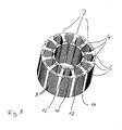
- Fig. 1 shows a perspective view of a laminated core according to the present invention in the form of a stator for an electric motor.
- a stator for example in an electric motor to drive used a heating circulation pump.
- the stator consists of twelve Stator segments 2.
- the stator segments 2 are T-shaped in a known manner formed with radially inwardly directed pole legs. 4 Around the pole leg 4 around the stator windings are (not here shown) arranged or wound. Transverse to the pole pieces 4 extend on the radial outer side of the stator segments 2 in the circumferential direction Polring sections 6.
- the entire stator segments are as Sheet metal package of a variety of identical stacked on top of each other Sheets 8 formed.
- the twelve individual stator segments 2 are a stator ring joined, with the individual stator segments 2 in the area their Polringabête 6 are connected to each other, so that a closed pole ring is formed on the outer circumference of the stator.
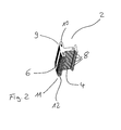
- Fig. 2 is a single stator segment of the stator shown in Fig. 1 in detail.
- the engagement projection 10 and the engagement groove 12 extend over the entire length, respectively the associated side edge of the Polringabiteses 6.
- Engagement projection 10 and engagement groove 12 over the entire length a constant cross section.
- the engagement projection 10 is formed by protrusions and the engagement groove 12 correspondingly through recesses formed the individual sheets 8.
- engagement groove 12 extend and engaging projection 10 in the circumferential direction of the stator, so that an assembly the stator segments in this direction is possible.
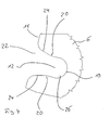
- FIG. 3 shows a schematic plan view of the engagement projection 10.
- the engagement projection 10 extends from a side edge 9 of the Polringabiteses 6 of a stator 2. It is front free end of the engagement projection 10 in cross-section substantially formed as a circular portion 14.
- the circular section 14 is connected to the side edge 9 via a web 16, which starting from the circular portion 14 to the side edge 9 extended.
- the connection of the web 16 to the circular Section 14 takes place in the region of one of the diameter of the circular Section 14 spaced chord, so between bridge 16 and circular section 14 constrictions 18 are formed.
- the engagement groove 12 has a circular cross-section Contour on, which is essentially on the circular contour of the circular portion 14 matched to the engagement projection 10 is.
- the engagement groove 12 their side walls opposite projections 20, which form a narrowing or undercut. Starting from the projections 20 extends the engagement groove 12 to the slot opening 22nd out. The widening, the slot opening 22 facing sections 24 of the groove wall define a shape in cross section, which with the cross-sectional shape of the web 16 corresponds.
- Fig. 5 shows in cross section the assembled state of the engagement projection 10 according to FIG. 3 and the engagement groove 12 according to FIG. 4.
- the circular portion 14 With its diametrical direction located largest width of the projections 20 formed by the constriction or undercut in the engagement groove 12 pass. It is the diameter of the circular portion 14 is greater than that of the Distance between the protrusions 20 that it is between the protrusions 20 and the diametrically opposite outsides of the circular section 14 comes to such high pressure loads, that the material in the region of the circular portion 14 of the engagement projection 10 is plastically deformed and in the direction of insertion located behind the projections 20, that is, the groove bottom 19 facing extended portion 26 (see FIG.
- the engagement groove 12 and the engagement projection 10 are dimensioned that in the assembled state both in the area of the indentations 18 as well as between the circular portion 14 and the Groove bottom 19 free spaces remain. That's enough Space for receiving the plastically deformed material available. This will ensure that the adjacent stator segments 12 always with your side edges 9 and 11 defined for investment come. Further, the portions 24 of the groove wall with the side walls the web 16 of the engagement projection 10 in Appendix. In This area can always be a defined investment created which a geometrically predetermined positioning of the individual Stator segments 2 allows each other. Through the open spaces in the area the recesses 18 and the groove bottom 19 is ensured that the positioning in the circumferential direction is not in the deformation area between engagement projection 10 and engagement groove 12 takes place.
- FIGS. 6 and 7 show the engagement projection 10 and the engagement groove 12 according to FIG a second embodiment of the invention. 6 shows a view in the not yet completely assembled state and Fig. 7 shows the fully assembled state of engagement projection 10 and engagement groove 12.
- engagement projection 10 and engagement groove 12th As shown in FIGS. 6 and 7, all are explained with reference to FIGS. 3 to 5 Characteristics so that they do not repeat these features becomes.
- a wedge 28th formed, which, starting from the groove bottom 19 to the Slot opening 22 extends and tapers in this direction wedge-shaped.
- the wedge 28 is opposite to the end face of the engagement projection 10, that is in the region of the circular portion 14, a inwardly directed wedge-shaped recess 30 is formed. At the Tip of the wedge-shaped recess 30, this is also in the longitudinal direction of the engagement projection 10 extends groove-shaped.
- the arrangement of the wedge 28 and the recess 30 cause that when the engagement projection 10 is inserted into the engagement groove 12, the Wedge 28 engages in the recess 30, as shown in Fig. 7.
- the wedge 28 is so dimensioned that it has a larger width or larger cross-sectional area than the recess 30. This causes the wedge 28 widened by engagement in the recess 30, the engagement projection 10, so that the separated by the recess 30 parts of the circular Section 14 in the radial direction, transverse to the insertion direction of the engagement projection 10 pressed apart and preferably plastically be deformed. This causes the projections 20 in the engagement groove 12 of the circular portion 14 of the engagement projection 10 yet be more underrun. The clamping force of the circular section 14 in the engagement groove 12 behind the projections 20 is further increased, so that a firm mechanical connection of engagement projection and engagement groove is achieved.
- Fig. 8 shows a chain of stator segments 2 for forming an annular Stators similar to the stator shown in Fig. 1.
- the twelve stator segments 2 according to the embodiment in Fig. 8 already in a prefabricated manner to a Chain hinged together.
- the sheets 8 are all twelve stator segments 2 each punched in one piece. Only the two at End of the chain located stator segments 2 have an engagement projection 10 or an engagement groove 12 according to the above-described Embodiment, wherein the engagement groove 12 at one end of the Chain and the engagement projection 10 at the opposite end of Chain are formed.
- FIG. 9 shows a further embodiment of the prefabricated shown in FIG. 8 Chain of stator segments 2.
- the individual stator segments 2 according to FIG. 9 formed as separate components and by joints in the Area of Polringabête 6 connected to each other.
- the joining together to an annular stator takes place in the previously described Manner by engagement of the engagement projection 10 in the Engagement groove 12 at the opposite end of the chain.
Abstract
Description
Die Erfindung betrifft ein Blechpaket für elektromagnetische Anwendungen sowie ein Verfahren zur Herstellung eines solchen Blechpaketes. Blechpakete für elektromagnetische Anwendungen werden beispielsweise als Eisenkerne oder Eisenkreise in elektromagnetischen Maschinen und Anlagen eingesetzt. Dies können beispielsweise Blechpakete in Transformatoren oder Statoren von Elektromotoren sein.The invention relates to a laminated core for electromagnetic applications and a method for producing such a laminated core. Sheet metal packages for electromagnetic applications, for example as iron cores or iron circles in electromagnetic machines and equipment used. This can, for example, laminated cores in transformers or stators of electric motors.
Insbesondere bei kleinen Elektromotoren, welche in großen Stückzahlen gefertigt werden und beispielsweise als Antriebsmotoren von Pumpenaggregaten, insbesondere von Umwälzpumpen für Heizungsanlagen eingesetzt werden, ist eine kostengünstige Fertigung und Montage sämtlicher Bauteile erwünscht. Dies beinhaltet auch eine kostengünstige Herstellung des Stators.Especially for small electric motors, which are in large quantities be manufactured and, for example, as drive motors of pump units, in particular of circulating pumps for heating systems used, is a cost-effective production and assembly all components desired. This also includes a cost effective Production of the stator.
Um in elektromagnetischen Einrichtungen insbesondere in Elektromotoren Wicklungen für Spulen auf die Blechpakete leichter aufbringen zu können, werden diese aus Segmenten gefertigt. Auf die einzelnen Segmente werden zunächst die Spulen aufgebracht. Anschließend werden die Segmente in ihrer endgültigen Position fest miteinander verbunden. Hierzu ist beispielsweise aus US 5,786,651 sowie US 6,219,900 B1 bekannt, einzelne Statorsegmente mit Hilfe von Steckverbindungen miteinander zu verbinden. Dazu ist jeweils an einer Seite eines Statorsegmentes eine Nut und an der entgegengesetzten Seite ein korrespondierender Vorsprung ausgebildet, welcher in die Nut des angrenzenden Segmentes eingreift. Dabei wird eine Rastverbindung zwischen Vorsprüngen und Nut bzw. eine kraftschlüssige Verbindung zwischen Vorsprung und Nut gebildet, welche aufgrund der elastischen Rückstellkräfte der Nutwandungen zusammen gehalten wird. Diese Anordnung hat den Nachteil, dass die Nuten und Vorsprünge mit großer Präzision gefertigt werden müssen, um die für die Passung erforderlichen Toleranzen einzuhalten. Insbesondere bei großen Stückzahlen sind die erforderlichen Toleranzen beispielsweise aufgrund des Werkzeugverschleißes nur schwer einzuhalten.To be in electromagnetic devices, especially in electric motors Windings for coils on the laminated cores easier to apply can be made from segments. On the individual Segments are first applied to the coils. Subsequently The segments are fixed together in their final position connected. For example, US 5,786,651 and US 6,219,900 B1 known, individual stator segments by means of connectors to connect with each other. This is on each side of a stator segment a groove and on the opposite side a corresponding one Protrusion formed in the groove of the adjacent Segmentes intervenes. This is a snap connection between Projections and groove or a frictional connection between Projection and groove formed, which due to the elastic restoring forces the groove walls is held together. This arrangement has the disadvantage that the grooves and protrusions with great precision must be made to the required for the fit To comply with tolerances. Especially for large quantities are the required tolerances, for example, due to the tool wear difficult to keep.
Es ist daher Aufgabe der Erfindung, ein Blechpaket für elektromagnetische Anwendungen sowie ein korrespondierendes Verfahren zur Herstellung eines solchen Blechpakets zu schaffen, welche eine zuverlässige Verbindung zwischen einzelnen Segmenten des Blechpaketes sicherstellen und kostengünstig herzustellen sind.It is therefore an object of the invention to provide a laminated core for electromagnetic Applications as well as a corresponding method for the production to create such a laminated core, which is a reliable Ensure connection between individual segments of the laminated core and inexpensive to manufacture.
Diese Aufgabe wird durch ein Blechpaket für elektromagnetische Anwendungen
mit den im Anspruch 1 angegebenen Merkmalen sowie
durch ein Verfahren zur Herstellung eines Blechpaketes mit den im Anspruch
14 angegebenen Merkmalen gelöst. Bevorzugte Ausführungsformen
ergeben sich aus den zugehörigen Unteransprüchen.This task is accomplished by a laminated core for electromagnetic applications
with the features specified in
Das erfindungsgemäße Blechpaket für elektromagnetische Anwendungen weist zumindest zwei Segmente auf, von denen zumindest eines an einer Seitenkante eine Eingriffsnut und das andere an einer gegenüberliegenden Seitenkante einen korrespondierenden Eingriffsvorsprung aufweist. Über die Eingriffsnut und den Eingriffsvorsprung können die beiden Segmente zu einem Bauteil verbunden werden. Ferner kann an jedem Segment eine Eingriffsnut und an der entgegengesetzten Seite ein Eingriffsvorsprung ausgebildet sein, sodass die einzelnen Segmente jeweils mit zwei angrenzenden Segmenten verbunden werden können. Alternativ können auch mehrere Segmente auf andere Weise miteinander verbunden sein, sodass nur einzelne Segmente in der beschriebenen Weise miteinander verbunden werden. The laminated core according to the invention for electromagnetic applications has at least two segments, of which at least one on one side edge an engagement groove and the other on an opposite Side edge a corresponding engagement projection having. About the engagement groove and the engagement projection can the two segments are connected to form a component. Furthermore, can on each segment an engagement groove and on the opposite Side be formed an engagement projection, so that the individual segments each connected to two adjacent segments can. Alternatively, multiple segments can be used in other ways be interconnected so that only individual segments in the described Be connected with each other.
Erfindungsgemäß weist die Eingriffsnut eine Hinterschneidung in Form eines von der Nutöffnung beabstandeten erweiterten Abschnittes auf, das heißt die Nut ist beabstandet vom Nutgrund verengt bzw. in der Nähe des Nutgrundes verbreitert ausgebildet. Der Eingriffsvorsprung und die Eingriffsnut sind ferner derart aufeinander abgestimmt dimensioniert, dass durch Einsetzen des Eingriffsvorsprunges in die Eingriffsnut der Eingriffsvorsprung und/oder die Eingriffsnut plastisch verformt werden. Durch die plastische Verformung fließt Material des Eingriffsvorsprunges in den erweiterten Bereich der Nut, sodass der verengte Bereich der Nut bzw. die Hinterschneidung hintergriffen wird und somit eine formschlüssige Verbindung der beiden Segmente erreicht wird. Zusätzlich kann der Eingriffsvorsprung eine Einschnürung beabstandet von der Stirnkante des Eingriffsvorsprunges aufweisen, sodass auch der Eingriffsvorsprung eine Hinterschneidung aufweist. So kann auch Material der Eingriffsnut in den Bereich der Einschnürung des Eingriffsvorsprunges fließen und eine formschlüssige Verbindung herstellen.According to the engagement groove has an undercut in shape an extended portion spaced from the groove opening; that is, the groove is spaced from the groove bottom narrows or in the Broadened near the groove bottom formed. The engaging projection and the engagement groove are further dimensioned in such a coordinated manner, by inserting the engagement projection into the engagement groove the engagement projection and / or the engagement groove are plastically deformed. Due to the plastic deformation flows material of the engagement projection in the extended area of the groove, so the narrowed area the groove or the undercut is engaged behind and thus a positive connection of the two segments is achieved. In addition, the engagement protrusion may be spaced a constriction from the front edge of the engagement projection, so that the Engaging projection has an undercut. So can material the engagement groove in the region of the constriction of the engagement projection flow and make a positive connection.
Dadurch, dass Nut und Eingriffsvorsprung so dimensioniert sind, dass es beim Einsetzen zu einer plastischen Verformung kommt, kann immer eine ausreichend feste Verbindung zwischen den zwei Segmenten des Blechpaketes sichergestellt werden. Dabei müssen weniger enge Toleranzen eingehalten werden, als wenn eine rein kraftschlüssige Verbindung bedingt durch elastische Rückstellkräfte der Eingriffsnut hergestellt wird. Durch die Dimensionierung von Eingriffsvorsprung und Hinterschneidung, welche zu einer plastischen Verformung des Materials führen, wird erreicht, dass sich beim Zusammenfügen das Material zunächst plastisch verformt, so dass eine vorgegebene Toleranz zwischen Eingriffsvorsprung und Eingriffsnut bzw. Hinterschneidung erzeugt wird. Durch die plastische Verformung erfolgt somit zunächst eine Kalibrierung des Übermaßes zwischen Eingriffsvorsprung und Eingriffsnut. Characterized in that groove and engagement projection are dimensioned so that it when inserting to a plastic deformation comes, always can a sufficiently strong connection between the two segments of the Sheet metal package can be ensured. There are less tight tolerances be complied with, as if a purely positive connection Conditionally produced by elastic restoring forces of the engagement groove becomes. By dimensioning the engaging projection and the undercut, which lead to a plastic deformation of the material, is achieved when joining the material first plastically deformed, leaving a given tolerance between Engagement projection and engagement groove or undercut is generated. The plastic deformation thus initially results in a calibration the excess between engagement projection and engagement groove.
Um die plastische Verformung beim Ineinandersetzen von Eingriffsvorsprung und Eingriffsnut zu erreichen, ist ein größeres Übermaß zwischen Eingriffsnut und Eingriffsvorsprung vorgesehen, d. h. die Eingriffsnut ist zumindest in Abschnitten vorzugsweise kleiner als der aufzunehmende Eingriffsvorsprung ausgebildet. Dadurch werden beim Einsetzen des Eingriffsvorsprunges, zumindest in Bereichen der Anlagefläche, hohe Flächenpressungen zwischen der Eingriffsnut und dem Eingriffsvorsprung erzeugt. Diese führen wiederum zu so hohen Spannungen insbesondere im Material des Eingriffsvorsprunges, dass die Spannungen die Fließgrenze des Materials übersteigen und so zu einer plastischen Verformung des Materials führen.To the plastic deformation when engaging engagement projection and to achieve engagement groove is a greater oversize between Engagement groove and engagement projection provided, d. H. the engagement groove is at least in sections, preferably smaller than the male Formed engagement projection. This will be at the onset of Eingriffsvorsprunges, at least in areas of the contact surface, high Surface pressures between the engagement groove and the engagement projection generated. These in turn lead to such high voltages in particular in the material of the engaging projection, that the stresses are the yield point of the material and thus to a plastic deformation of the material.
Bevorzugt ist das Blechpaket als Stator für einen Elektromotor, vorzugsweise für ein Pumpenaggregat ausgebildet, wobei der Stator zumindest zwei Segmente, das heißt Statorsegmente aufweist, von denen eines an einer Seitenkante die Eingriffsnut und das andere an einer gegenüberliegenden Seitenkante den korrespondierenden Eingriffsvorsprung aufweist. Auf diese Weise können Statoren für Elektromotoren, insbesondere für Pumpenaggregate wie beispielsweise für Heizungsumwälzpumpen in großen Stückzahlen sehr kostengünstig gefertigt werden. Die in bekannter Weise aus einzelnen Blechen zusammengesetzten Statorsegmente werden zunächst mit den erforderlichen Statorwicklungen versehen und dann über die Eingriffsnut und den Eingriffsvorsprung zu einem ringförmigen Stator zusammengesetzt. Dazu kann jedes Statorsegment an einer in Umfangsrichtung gerichteten Stirnseite einer Eingriffsnut und an der entgegengesetzten Stirnseite einen Eingriffsvorsprung aufweisen. Alternativ können einzelne Statorsegmente zuvor durch andere Verbindungsarten beweglich zu einer Kette verbunden sein, wobei das Statorsegment am ersten Ende der Kette an seiner freien Stirnkante eine Eingriffsnut und das Statorsegment am zweiten Ende der Kette an seiner freien Stirnkante einen korrespondierenden Eingriffsvorsprung aufweist. Durch Ineinandersetzten der Eingriffsnut und des Eingriffsvorsprunges kann die Kette dann zu einem ringförmigen Stator geschlossen werden. Die Verbindung der einzelnen Statorsegmente zu einer Kette kann beispielsweise durch schmale Blechstege erfolgen.Preferably, the laminated core as a stator for an electric motor, preferably designed for a pump unit, wherein the stator at least two segments, that is stator segments, one of which on one side edge of the engagement groove and the other on an opposite Side edge of the corresponding engagement projection having. In this way, stators for electric motors, in particular for pump units such as for heating circulation pumps be manufactured very inexpensively in large quantities. The in a known manner composed of individual sheets stator segments be first with the required stator windings and then over the engagement groove and the engagement projection to composed of an annular stator. This can be any stator segment on a circumferential end face of a Eingriffsnut and on the opposite end face an engagement projection exhibit. Alternatively, individual stator segments can be previously connected by other types of connections movable to a chain be with the stator at the first end of the chain at its free Front edge of an engagement groove and the stator at the second end the chain at its free end edge a corresponding engagement projection having. By interlocking the Eingriffsnut and the Eingriffsvorsprunges, the chain then to an annular stator getting closed. The connection of the individual stator segments too a chain can be done for example by narrow sheet metal webs.
Insbesondere eignet sich ein erfindungsgemäß ausgebildeter Stator zum Einsatz in einem nasslaufenden Spaltrohrmotor, wie er beispielsweise in Heizungsumwälzpumpen im Leistungsbereich von 10 bis 300 Watt eingesetzt wird. Bei Spaltrohrmotoren ist der Rotor im Spaltrohr gelagert. Aus diesem Grund muss das Statorgehäuse nur geringe Kräfte aufnehmen und kann vergleichsweise leicht ausgebildet werden. Durch die erfindungsgemäße feste Verbindung der einzelnen Statorsegmente untereinander wird dies weiter begünstigt, da so ein segmentierter, jedoch eigenstabiler Stator geschaffen wird, welcher nicht durch ein umgebendes Statorgehäuse zusammengehalten werden muss.In particular, a stator designed according to the invention is suitable For use in a wet-running canned motor, as he, for example in heating circulation pumps in the power range of 10 to 300 watts is used. For canned motors, the rotor is mounted in the canned tube. For this reason, the stator housing must absorb only small forces and can be made comparatively easy. By the Solid connection according to the invention of the individual stator segments this is further favored with each other, as such a segmented, however is created stably stable stator, which is not surrounded by a surrounding Stator housing must be held together.
Weiter bevorzugt weist der Eingriffsvorsprung einen Abschnitt auf, welcher in den erweiterten Abschnitt der Eingriffsnut eingreift, wobei die geringste Breite der Nut im Bereich zwischen Nutöffnung und Hinterschneidung derart auf die größte Breite des Abschnittes des Eingriffsvorsprungs abgestimmt ist, dass durch Einsetzen des Eingriffsvorsprunges in die Eingriffsnut der Eingriffsvorsprung und/oder die Eingriffsnut plastisch verformt werden. Insbesondere weist der Abschnitt des Eingriffsvorsprunges eine entsprechend größere Breite als die geringste Nutbreite auf. Der Abschnitt des Eingriffsvorsprunges mit der größten Breite passiert beim Zusammensetzen von Eingriffsvorsprung und Eingriffsnut den Bereich der kleinsten Breite der Eingriffsnut vor der Hinterschneidung. Dabei wird aufgrund der Breitendifferenz eine Druckkraft zwischen Eingriffsnut und Eingriffsvorsprung erzeugt. Diese wiederum führt zu Spannungen im Kontaktbereich zwischen Eingriffsnut und Eingriffsvorsprung. Der Bereich der kleinsten Nutbreite und der Bereich des Eingriffsvorsprungs mit der größten Breite sind dabei so dimensioniert, dass die auftretenden Spannungen die Fließgrenze des Materials übersteigen, sodass es zu einer plastischen Verformung des Materials kommt. Dabei kann der Abschnitt der Nut mit der geringsten Breite so eng und der Bereich des Eingriffsvorsprungs mit der größten Breite so breit gewählt werden, dass beim Zusammensetzen immer so hohe Spannungen sichergestellt sind, dass die Fließgrenze sicher überschritten wird. Um dies sicherzustellen sind gewisse Mindestdifferenzen im Maß von kleinster Nutbreite und größter Breite des Eingriffsvorsprunges einzuhalten. Es ist jedoch nicht erforderlich, derart genaue Toleranzen einzuhalten, wie sie für rein kraftschlüssige Passungen bzw. rein elastische Verbindungen erforderlich sind. Auf diese Weise können zum Beispiel Einflüsse des Werkzeugverschleißes beim Stanzen der Blechpakete minimiert werden.More preferably, the engagement projection has a portion which engages in the extended portion of the engagement groove, wherein the smallest width of the groove in the area between slot opening and undercut such to the greatest width of the portion of the engagement projection is agreed that by inserting the engagement projection in the engagement groove of the engagement projection and / or the engagement groove plastically be deformed. In particular, the portion of the engagement projection a correspondingly greater width than the smallest groove width on. The section of the engagement projection with the largest width happens when assembling engagement projection and engagement groove the Area of the smallest width of the engagement groove before the undercut. It is due to the width difference between a compressive force Engagement groove and engagement projection generated. This in turn leads to Tensions in the contact area between engagement groove and engagement projection. The area of the smallest groove width and the area of the engagement projection with the largest width are dimensioned so that the occurring stresses exceed the flow limit of the material, so that it comes to a plastic deformation of the material. In this case, the portion of the groove with the smallest width so narrow and the area of the engagement projection with the largest width selected so wide be that when assembling always so high voltages it is ensured that the yield point is safely exceeded. Around To ensure this are certain minimum differences in the measure of smallest Groove width and greatest width of the engagement projection to comply. It However, it is not necessary to comply with such exact tolerances as they are for purely frictional fits or purely elastic connections required are. In this way, influences of the Tool wear can be minimized when punching the laminated cores.
Ferner kann die geringste Breite der Nut im Bereich zwischen Nutöffnung und Hinterschneidung derart auf die größte Breite eines verbreiterten Abschnittes des Eingriffsvorsprunges abgestimmt sein, dass beim Einsetzen des Eingriffsvorsprunges in die Eingriffsnut zusätzlich zu der plastischen Verformung eine elastisch Verformung der Eingriffsnut auftritt. Diese elastische Verformung bewirkt, dass sich die Nut beim Einsetzen des Eingriffsvorsprunges zunächst aufweitet und dann, wenn der verbreitete Abschnitt des Eingriffsvorsprunges den Abschnitt der geringsten Breite der Nut, das heißt die Hinterschneidung passiert hat, wieder elastisch zusammenzieht, sodass der Eingriffsvorsprung mit seinem verbreiterten Abschnitt die Hinterschneidung der Nut hintergreift. Zusätzlich kommt es erfindungsgemäß zu der bereits beschriebenen plastischen Verformung der Eingriffsnut und/oder des Eingriffsvorsprunges. Die plastische Verformung bewirkt, dass Eingriffsnut und/oder Eingriffsvorsprung beim Fügen zunächst plastisch auf das für die elastische Verformung erforderliche Übermaß verformt werden. D. h. das Übermaß bzw. die Breitendifferenz zwischen Eingriffsvorsprung und Eingriffsnut ist erfindungsgemäß größer gewählt als für das Einrasten bzw. Einschnappen unter elastischer Verformung erforderlich. Durch die plastische Verformung wird das Übermaß auf das für den elastischen Eingriff erforderliche Maß reduziert. Auf diese Weise kann trotz großer Toleranzbereiche stets eine sichere Rastverbindung zwischen Eingriffsnut und Eingriffsvorsprung sichergestellt werden. Beim Ineinanderfügen kalibrieren sich die Teile durch plastische Verformung selbsttätig auf das gewünschte Maß. So kann das relative Übermaß zwischen dem breitesten Teil des Eingriffsvorsprungs und der engsten Stelle der Eingriffsnut sehr groß toleriert werden, beispielsweise im Bereich von 1/100 bis 10/100 mm liegen.Furthermore, the smallest width of the groove in the region between slot opening and undercut to the largest width of a widened so Be matched to the section of the engagement projection that at Insertion of the engagement projection in the engagement groove in addition to the plastic deformation occurs an elastic deformation of the engagement groove. This elastic deformation causes the groove during insertion of the engagement projection first expands and then when the spread portion of the engaging projection the portion of the least Width of the groove, that is, the undercut has happened contracts elastically again so that the engagement projection with his widened portion engages behind the undercut of the groove. In addition, it comes according to the invention to those already described plastic deformation of the engagement groove and / or the engagement projection. The plastic deformation causes engagement groove and / or engagement projection When joining, first plastically on the elastic Deformation required oversize be deformed. Ie. the excess or the width difference between the engagement projection and the engagement groove inventively chosen larger than for snapping or snapping required under elastic deformation. By the plastic deformation the excess will be required for the elastic engagement Measure reduced. In this way, despite large tolerance ranges always a secure locking connection between the engagement groove and engagement projection be ensured. When merging, the calibrate Parts by plastic deformation automatically to the desired level. Thus, the relative excess between the widest part of the engagement projection and the narrowest point of the engagement groove tolerated very large be, for example, in the range of 1/100 to 10/100 mm.
Besonders bevorzugt erstreckt sich die Eingriffsnut mit vorzugsweise konstantem Querschnitt über die gesamte axiale Länge des Segmentes des Blechpaketes. Auf diese Weise kann eine sichere Verbindung des Segmentes mit einem angrenzenden Segment über die gesamte Länge der Segmente erreicht werden. Im Falle dass die Segmente Statorsegmente sind, erstreckt sich die Eingriffsnut vorzugsweise parallel zur Längsachse des Stators entlang einer Seiten- bzw. Stirnkante des Statorsegmentes.Particularly preferably, the engagement groove extends with preferably constant Cross section over the entire axial length of the segment the laminated core. In this way, a secure connection of the Segment with an adjacent segment along its entire length the segments are reached. In case the segments are stator segments are, the engagement groove preferably extends parallel to Longitudinal axis of the stator along a side or front edge of the stator.
Weiter bevorzugt erstreckt sich der Eingriffsvorsprung mit vorzugsweise konstantem Querschnitt über die gesamte axiale Länge des Segmentes. Damit kann sichergestellt werden, dass das Segment über die gesamte Länge mit einem angrenzenden Segment in Eingriff ist und so eine feste Verbindung herstellt. Wenn das Segment ein Statorsegment eines Stators bildet, erstreckt sich der Eingriffsvorsprung vorzugsweise an einer Stirnseite bzw. Stirnkante des Statorsegmentes parallel zur Statorlängsachse.More preferably, the engagement projection preferably extends constant cross section over the entire axial length of the segment. This can ensure that the segment over the entire Length is engaged with an adjacent segment and so on makes a firm connection. If the segment is a stator segment a stator, the engagement projection preferably extends a front side or end edge of the stator parallel to the stator longitudinal axis.
Der Eingriffsvorsprung weist besonders bevorzugt einen runden, vorzugsweise kreisförmigen Querschnitt auf, von dem aus sich ein Steg zu der Seitenkante des Segmentes erstreckt. Durch den runden Querschnitt des Vorsprunges wird erreicht, dass der Eingriffsvorsprung nur mit zwei kleinen diametral entgegengesetzten Umfangsabschnitten mit den Wandungen der Eingriffsnut in Kontakt kommt. Es kommt somit vorzugsweise im Wesentlichen nur zu einem Linienkontakt, wodurch sich beim Einsetzen des Eingriffsvorsprungs in die Eingriffsnut die in diesem Bereich auftretenden Spannungen so erhöhen, dass die Fließgrenze des Materials überschritten wird und das Material des Eingriffsvorsprunges hinter die Hinterschneidung der Eingriffsnut gedrückt wird bzw. fließen kann. Anstelle des kreisförmigen Querschnitts kann auch ein ovaler oder anders geformter Querschnitt mit kleinen Kontaktflächen zum Einsatz kommen. Durch den schmalen Kontaktbereich, vorzugsweise in Form eines Linienkontaktes zwischen Eingriffsnut und Eingriffsvorsprung, kann eine ausreichend große Kraft zur Überwindung der Fließgrenze in einem breiten Toleranzbereich des relativen Übermaßes zwischen Eingriffsnut und Eingriffsvorsprung, z. B. im Bereich von 1/100 bis 10/100 mm, sichergestellt werden. Gleichzeitig werden in dem kleinen bzw. schmalen Kontaktbereich auch bei geringen Fügekräften ausreichend große Flächenpressungen zur Überwindung der Fließgrenze erreicht. Die geringen Fügekräfte haben den Vorteil, dass eine Beschädigung der zu fügenden Segmente und insbesondere ein Auftrennen der einzelnen Bleche vermieden wird.The engagement projection particularly preferably has a round, preferably circular cross-section on, from which a bridge to the side edge of the segment extends. Due to the round cross section of the projection is achieved that the engagement projection only with two small diametrically opposite peripheral sections with the walls of the engagement groove comes into contact. It is thus preferable essentially only to a line contact, resulting in when inserting the engagement projection in the engagement groove in this Increase the area occurring in such a way that the yield point of the Material is exceeded and the material of the engaging projection is pressed behind the undercut of the engagement groove or flow can. Instead of the circular cross section can also be an oval or differently shaped cross-section with small contact surfaces for use come. Due to the narrow contact area, preferably in shape a line contact between engagement groove and engagement projection, can a sufficiently large force to overcome the yield point in one wide tolerance range of the relative excess between the engagement groove and engaging projection, z. B. in the range of 1/100 to 10/100 mm, ensured become. At the same time in the small or narrow Contact area even at low joining forces sufficiently large surface pressures reached to overcome the yield point. The small one Joining forces have the advantage that damage to be joined Segments and in particular a separation of the individual sheets is avoided.
Vorzugsweise erweitert sich der Steg ausgehend von dem runden Querschnitt zu der Seitenkante des Segmentes. Auf diese Weise wird der Steg im Grenzbereich zu dem Segment verstärkt, sodass eine unerwünschte Verformung des Steges in diesem Bereich vermieden werden kann.Preferably, the bridge widens from the round Cross section to the side edge of the segment. This way will the web is reinforced in the border area to the segment, so that an undesirable Deformation of the web in this area can be avoided can.
Entsprechend erweitert sich die Eingriffsnut vorzugsweise ausgehend von Ihrem Bereich mit der geringsten Breite zur Nutöffnung hin. Auf diese Weise wird das Einsetzen des Eingriffsvorsprunges erleichtert und sichergestellt, dass es beim Einsetzen des Eingriffsvorsprunges nicht zu einer unerwünschten plastischen Verformung in diesem Bereich der Eingriffsnut kommen kann. Accordingly, the engagement groove preferably expands outwardly from your area with the smallest width to the slot opening. To this Way the insertion of the engagement projection is facilitated and ensured that it is not at the onset of engagement protrusion an undesirable plastic deformation in this area of Engagement groove can come.
Zweckmäßigerweise weist die Eingriffsnut eine derart größere Querschnittsfläche als der Eingriffsvorsprung auf, dass Freiräume zur Aufnahme des plastisch verformten Materials ausgebildet sind. Auf diese Weise wird sichergestellt, dass Eingriffsvorsprung und Eingriffsnut sicher unter plastischer Verformung so weit zusammen gefügt werden können, dass das verformte Material in den erweiterten Bereich, das heißt hinter die Hinterschneidung der Eingriffsnut eintritt. Durch entsprechend große Ausbildung der Freiräume kann sichergestellt werden, dass die zwei zu verbindenden Segmente des Blechpaketes immer an definierten Anlageflächen aneinander anliegen und zueinander positioniert werden.Conveniently, the engagement groove has such a larger cross-sectional area as the engaging projection on that clearance for admission of the plastically deformed material are formed. In this way Ensures that engagement projection and engagement groove safely under plastic deformation can be joined together so far that the deformed material in the extended area, that is behind the Undercut of the engagement groove occurs. By correspondingly large Training the freedoms can be ensured that the two too connecting segments of the laminated core always at defined contact surfaces abut each other and be positioned to each other.
Dabei ist insbesondere bevorzugt, dass die einzelnen Segmente jeweils mit ihren Seitenkanten aneinander zur Anlage kommen. Dadurch wird eine definierte Positionierung der Segmente relativ zueinander sichergestellt. Insbesondere bei einem Stator wird so sichergestellt, das die Statorsegmente im Bereich ihrer Seitenkanten definiert aneinander anliegen und in Umfangsrichtung nicht undefiniert im Verformungsbereich von Eingriffsvorsprung und Eingriffsnut zur Anlage kommen. Auch dies wird vorzugsweise durch genügend große Freiräume zur Aufnahme des plastisch verformten Materials erreicht.It is particularly preferred that the individual segments each come with their side edges to each other to the plant. This will ensures a defined positioning of the segments relative to each other. In particular, in a stator is thus ensured that the Stator segments in the region of their side edges defined abut each other and not undefined in the deformation area in the circumferential direction come from engagement projection and engagement groove to the plant. This too is preferably by sufficiently large open spaces to accommodate the achieved plastically deformed material.
Gemäß einer speziellen Ausführungsform kann in der Eingriffsnut im Bereich des Nutbodens ein Verformungselement angeordnet sein, welches den eingreifenden Eingriffsvorsprung derart verformt, dass er in den erweiterten Abschnitt der Eingriffsnut eingreift und die Hinterschneidung um- bzw. hintergreift. Diese Anordnung bewirkt, dass die plastische Verformung des Eingriffsvorsprunges nach Passieren der Hinterschneidung, das heißt des Bereiches der Nut mit der geringsten Breite, durch das Verformungselement eingeleitet oder verstärkt wird. Durch das Verformungselement wird der Eingriffsvorsprung an seinem in Einsetzrichtung vorderen Ende so verformt bzw. aufgeweitet, dass er die Hinterschneidung in der Eingriffsnut hintergreift. Die zusätzliche Aufweitung des Eingriffsvorsprungs durch das Verformungselement ermöglicht, eine größere Hinterschneidung auszubilden, so dass eine festere Verbindung zwischen den aneinander angrenzenden Segmenten erreicht werden kann. Zusätzlich können Eingriffsvorsprung und Eingriffsnut auch so dimensioniert sein, dass es bereits beim Passieren des Abschnittes mit der geringsten Nutbreite durch den Eingriffsvorsprung zu einer plastischen Verformung von Eingriffsvorsprung und/oder Eingriffsnut kommt. Das Verformungselement kann beispielsweise als Keil ausgebildet sein, welcher sich vom Nutboden in Einschubrichtung zur Nutöffnung erstreckt und in dieser Richtung verjüngt.According to a specific embodiment, in the engagement groove in the area be arranged a deformation element of the groove bottom, which the engaging engagement projection deformed so that it engages the extended portion of the engagement groove and the undercut surrounds or engages behind. This arrangement causes the plastic deformation of the engagement projection after passing the undercut, that is, the area of the groove having the smallest width, initiated or reinforced by the deformation element. By the deformation element of the engagement projection on his in Inset direction front end so deformed or expanded that he Undercut engages behind the engagement groove. The additional expansion allows the engagement projection by the deformation element, form a larger undercut, allowing a firmer connection reached between the adjacent segments can be. In addition, engagement projection and engagement groove can also be so dimensioned that it is already passing the section with the smallest groove width through the engagement projection to a plastic Deformation of engagement projection and / or engagement groove comes. The deformation element may be formed, for example, as a wedge, which extends from the groove bottom in the direction of insertion to the slot opening and rejuvenated in that direction.
Die Segmente bestehen bevorzugt aus einer Vielzahl von Blechen, wobei in jedem Segment zumindest ein Blech mit einem Eingriffsvorsprung, welcher mit einer Eingriffsnut eines angrenzenden Segmentes unter plastischer Verformung im Eingriff ist, und zumindest ein Blech mit einer Eingriffsnut, welches mit einem Eingriffsvorsprung eines angrenzenden Segmentes unter plastischer Verformung im Eingriff ist, ausgebildet sind. Dies bedeutet, dass in dem Segment bzw. Blechpaket nicht jedes Blech so ausgebildet sein muss, dass es Eingriffsvorsprung und/oder Eingriffsnut aufweist, welche mit einer korrespondierenden Eingriffsnut bzw. einem korrespondierenden Eingriffsvorsprung eines angrenzenden Segmentes in der vorangehend beschriebenen Weise unter plastischer Verformung in Eingriff sind. Es ist ausreichend, dass einzelne Bleche der Segmente bzw. Blechpakete so dimensioniert sind, dass immer zumindest ein Blech des Segmentes erfindungsgemäß mit einem Blech eines angrenzenden Segmentes über Eingriffsnut und Eingriffsvorsprung unter plastischer Verformung in Eingriff ist.The segments are preferably made of a plurality of sheets, wherein in each segment at least one metal sheet with an engaging projection, which with an engagement groove of an adjacent segment below plastic deformation is engaged, and at least one sheet with a Eingriffsnut, which with an engaging projection of an adjacent Segmentes under plastic deformation is engaged, are formed. This means that in the segment or laminated core not every sheet must be designed so that it engagement projection and / or Eingriffsnut having, which with a corresponding engagement groove or a corresponding engagement projection of an adjacent segment in the manner described above under plastic deformation are engaged. It is sufficient that individual sheets of the segments or laminated cores are dimensioned so that always at least one sheet of the segment according to the invention with a metal sheet of an adjacent Segmentes via engagement and engagement projection under plastic deformation is engaged.
Die Erfindung betrifft ferner ein Verfahren zur Herstellung eines Blechpaketes gemäß der vorangehenden Beschreibung. Das Blechpaket ist aus mindestens zwei Segmenten zu einem Bauteil zusammengesetzt. Von den beiden Segmenten weist zumindest eines an einer Seitenkante eine Eingriffsnut und das andere an einer der Seitenkante des ersten Segmentes gegenüberliegenden Seitenkante einen korrespondierenden Eingriffsvorsprung auf. Um das Blechpaket zusammenzusetzen, werden die Segmente so aneinander gefügt, dass der Eingriffsvorsprung des ersten Segmentes in die Eingriffsnut des anderen angrenzenden Segmentes eingreift. Auf diese Weise wird eine formschlüssige Verbindung zwischen den beiden Segmenten hergestellt.The invention further relates to a method for producing a laminated core as described above. The laminated core is out at least two segments combined to form a component. From the two segments has at least one on one side edge Eingriffsnut and the other at one of the side edge of the first Segmentes opposite side edge of a corresponding Engaging projection on. To assemble the laminated core, The segments are joined together so that the engagement projection of the first segment in the engagement groove of the other adjacent Segmentes intervenes. In this way, a form-fitting Connection made between the two segments.
Erfindungsgemäß wird die Eingriffsnut mit einer Hinterschneidung in Form eines von der Nutöffnung beabstandeten erweiterten Abschnittes ausgebildet. Das heißt die Nut wird beabstandet vom Nutgrund bzw. Nutboden eingeschnürt bzw. verengt ausgebildet. Ferner werden der Eingriffsvorsprung und die Eingriffsnut derart in ihren Dimensionen aufeinander abgestimmt, dass es beim Einsetzen des Eingriffsvorsprunges in die Eingriffsnut zu einer plastischen Verformung des Eingriffsvorsprunges und/oder der Eingriffsnut kommt. Durch diese plastische Verformung wird erreicht, dass der Eingriffsvorsprung im Zusammengesetzten Zustand der beiden Segmente in den erweiterten Abschnitt der Eingriffsnut eingreift und so die Hinterschneidung hintergreift und eine formschlüssige Verbindung herstellt. Die plastische Verformung des Eingriffsvorsprunges und/oder des die Eingriffsnut umgebenden Materials wird dadurch erreicht, dass Eingriffsnut und Eingriffsvorsprung so dimensioniert werden, dass es beim Zusammensetzen von Eingriffsnut und Eingriffsvorsprung zu so hohen Druckkräften zwischen Eingriffsnut und Eingriffsvorsprung kommt, dass die Spannungen im Inneren des Materials die Fließgrenze übersteigen, dass Material plastisch verformt wird und in den erweiterten Abschnitt der Eingriffsnut gedrückt wird, um die Hinterschneidung zu umgreifen. Zusätzlich kann Material, am Rande der Eingriffsnut in eine Einschnürung bzw. Ausnehmung am Eingriffsvorsprung gedrückt werden, sodass auch hier ein formschlüssiger Eingriff zwischen Eingriffsvorsprung und Eingriffsnut durch plastische Verformung erreicht wird. According to the engagement groove with an undercut in Shape of an extended portion spaced from the groove opening educated. That is, the groove is spaced from the groove bottom or Grooved bottom constricted or formed narrowed. Furthermore, the Engagement projection and the engagement groove so in their dimensions to each other agreed that when inserting the engaging projection in the engagement groove to a plastic deformation of the engagement projection and / or the engagement groove comes. Through this plastic deformation is achieved that the engaging projection in the assembled state the two segments in the extended portion of the engagement groove engages and thus engages behind the undercut and a form-fitting Makes connection. The plastic deformation of the engagement projection and / or the material surrounding the engagement groove achieved in that engagement groove and engagement projection dimensioned so be that when assembling engagement groove and engagement projection to such high pressure forces between the engagement groove and the engagement projection comes that tensions inside the material exceed the flow limit that material is plastically deformed and in the extended portion of the engagement groove is pressed to the undercut to embrace. In addition, material may be on the verge of Engagement groove in a constriction or recess on the engagement projection are pressed so that here is a positive engagement between engagement projection and engagement groove by plastic deformation is reached.
Bevorzugt ist das Verfahren so ausgebildet, dass der Eingriffsvorsprung einen Abschnitt aufweist, welcher in den erweiterten Abschnitt der Eingriffsnut eingreift, wobei die geringste Breite der Nut im Bereich zwischen Nutöffnung und Hinterschneidung derart auf die größte Breite des Abschnittes des Eingriffsvorsprunges abgestimmt ist, dass sich beim Einsetzen des Eingriffsvorsprunges in die Eingriffsnut der Eingriffsvorsprung und/oder die Eingriffsnut plastisch verformen. Der Abschnitt des Eingriffsvorsprungs wird so dimensioniert, dass er eine größere Breite als die kleinste Breite der Eingriffsnut aufweist. So kommt es zwischen diesem Abschnitt, wenn dieser den Bereich der Nut mit der geringsten Breite passiert, zu den erforderlichen hohen Druckkräften bzw. Flächenpressungen.Preferably, the method is designed such that the engagement projection has a section which in the extended section of Engaging groove engages, with the smallest width of the groove in the range between Groove opening and undercut so on the largest width the section of the engagement projection is matched that at the Inserting the engagement projection into the engagement groove of the engagement projection and / or plastically deform the engagement groove. The section of the The engaging projection is dimensioned to have a greater width than having the smallest width of the engagement groove. So it happens between this Section, if this is the area of the groove with the smallest width happens to the required high compressive forces or surface pressures.
Besonders bevorzugt kommt es beim Einsetzen des Eingriffsvorsprunges in die Eingriffsnut zusätzlich zu der plastischen Verformung zu einer elastischen Verformung der Eingriffsnut. Dies bedeutet, dass die Eingriffsnut beim Einsetzen des Eingriffsvorsprunges aufgeweitet wird, wobei durch elastische Rückstellkräfte eine auf den Eingriffsvorsprung wirkende Klemmkraft erzeugt wird. Besonders bevorzugt wird die Eingriffsnut dann aufgeweitet, wenn der breiteste Abschnitt des Eingriffsvorsprunges die engste Stelle der Eingriffsnut vor der Hinterschneidung passiert. Wenn der erweiterte Abschnitt des Eingriffsvorsprunges dann in den erweiterten Abschnitt der Eingriffsnut hinter der Hinterschneidung eintritt, bewegen sich die Wandungen der Eingriffsnut aufgrund elastischer Rückstellkräfte wieder in ihre Ausgangslage zurück, sodass der Abschnitt mit der geringsten Breite der Nut den erweiterten Abschnitt des Eingriffsvorsprunges umgreift. Auf diese Weise wird eine Rastverbindung zwischen Eingriffsvorsprung und Eingriffsnut geschaffen.Particularly preferred is the insertion of the engagement projection in the engagement groove in addition to the plastic deformation to an elastic Deformation of the engagement groove. This means that the engagement groove widened upon insertion of the engagement projection, wherein elastic restoring forces acting on the engagement projection Clamping force is generated. Particularly preferably, the engagement groove is then widened when the widest portion of the engagement projection the narrowest point of the engagement groove before the undercut happens. If the extended portion of the engagement projection then in the extended Section of the engagement groove behind the undercut occurs, move the walls of the engagement groove due to elastic restoring forces back to their original position, so that the section with the smallest width of the groove, the extended portion of the engagement projection embraces. In this way, a snap connection between Engagement projection and engagement groove created.
Nachfolgend wird die Erfindung beispielhaft anhand der beigefügten Zeichnungen beschrieben. In diesen zeigt:
- Fig. 1
- eine perspektivische Ansicht eine Stators für einen Elektromotor gemäß der vorliegenden Erfindung,
- Fig. 2
- eine perspektivische Ansicht eines Statorsegmentes des in Fig. 1 gezeigten Stators,
- Fig. 3
- eine Detailansicht eines Eingriffsvorsprunges in einer Draufsicht,
- Fig. 4
- eine Detailansicht einer Eingriffsnut in einer Draufsicht,
- Fig. 5
- eine Ansicht des Eingriffsvorsprungs gemäß Fig. 3 und der Eingriffsnut gemäß Fig. 4 im verbundenen Zustand,
- Fig. 6
- eine Detailansicht von Eingriffsvorsprung und Eingriffsnut gemäß einer zweiten Ausführungsform der Erfindung im nicht vollständig verbunden Zustand,
- Fig. 7
- einen Ansicht von Eingriffsvorsprung und Eingriffsnut gemäß Fig. 6 im vollständig verbundenen Zustand,
- Fig. 8
- eine perspektivische Ansicht einer Kette von miteinander verbundenen Statorsegmenten gemäß einer besonderen Ausführungsform der Erfindung und
- Fig. 9
- eine perspektivische Ansicht einer Kette von Statorsegmenten gemäß einer weiteren Ausführungsform der Erfindung.
- Fig. 1
- a perspective view of a stator for an electric motor according to the present invention,
- Fig. 2
- a perspective view of a stator of the stator shown in Fig. 1,
- Fig. 3
- a detailed view of an engagement projection in a plan view,
- Fig. 4
- a detailed view of an engagement groove in a plan view,
- Fig. 5
- 3 shows a view of the engagement projection according to FIG. 3 and the engagement groove according to FIG. 4 in the connected state, FIG.
- Fig. 6
- a detailed view of engagement projection and engagement groove according to a second embodiment of the invention in the not fully connected state,
- Fig. 7
- 6 shows a view of the engagement projection and the engagement groove according to FIG. 6 in the fully connected state, FIG.
- Fig. 8
- a perspective view of a chain of interconnected stator segments according to a particular embodiment of the invention and
- Fig. 9
- a perspective view of a chain of stator segments according to another embodiment of the invention.
Fig. 1 zeigt in einer perspektivischen Ansicht ein Blechpaket gemäß der
vorliegenden Erfindung in Form eines Stators für einen Elektromotor. Ein
solcher Stator wird beispielsweise in einem Elektromotor zum Antrieb
einer Heizungsumwälzpumpe eingesetzt. Der Stator besteht aus zwölf
Statorsegmenten 2. Die Statorsegmente 2 sind in bekannter Weise T-förmig
ausgebildet mit radial nach innen gerichteten Polschenkeln 4.
Um die Polschenkel 4 herum werden die Statorwicklungen (hier nicht
gezeigt) angeordnet bzw. gewickelt. Quer zu den Polschenkeln 4 erstrecken
sich an der radialen Außenseite der Statorsegmente 2 in Umfangsrichtung
Polringabschnitte 6. Die gesamten Statorsegmente sind als
Blechpaket aus einer Vielzahl von identischen aufeinander gestapelten
Blechen 8 ausgebildet.Fig. 1 shows a perspective view of a laminated core according to the
present invention in the form of a stator for an electric motor. One
such stator is used for example in an electric motor to drive
used a heating circulation pump. The stator consists of twelve
Wie gezeigt, sind die zwölf einzelnen Statorsegmente 2 zu einem Statorring
zusammengefügt, wobei die einzelnen Statorsegmente 2 im Bereich
ihrer Polringabschnitte 6 miteinander verbunden sind, sodass ein
geschlossener Polring am Außenumfang des Stators gebildet wird. Dazu
sind an jedem Statorsegment an in Umfangsrichtung entgegengesetzten
Seiten bzw. Stirnkanten 9, 11 der Polringabschnitte 6 Eingriffsvorsprünge
10 und Eingriffsnuten 12 ausgebildet, wobei an jedem Statorsegment
2 an einer Seitenkante 9 ein Eingriffsvorsprung 10 und an der
entgegengesetzten Seitenkante 11 eine Eingriffsnut 12 ausgebildet ist.As shown, the twelve
Dies ist deutlicher in Fig. 2 zu sehen, welche ein einzelnes Statorsegment
des in Fig. 1 gezeigten Stators im Detail zeigt. Der Eingriffsvorsprung 10
und die Eingriffsnut 12 erstrecken sich jeweils über die gesamte Länge
der zugehörigen Seitenkante des Polringabschnittes 6. Dabei weisen
Eingriffsvorsprung 10 und Eingriffsnut 12 über die gesamte Länge einen
konstanten Querschnitt auf. Der Eingriffsvorsprung 10 wird durch Vorsprünge
und die Eingriffsnut 12 entsprechend durch Ausnehmungen an
den einzelnen Blechen 8 gebildet. Ferner erstrecken sich Eingriffsnut 12
und Eingriffsvorsprung 10 in Umfangsrichtung des Stators, sodass ein Zusammenfügen
der Statorsegmente in dieser Richtung möglich ist.This is more clearly seen in Fig. 2, which is a single stator segment
of the stator shown in Fig. 1 in detail. The
Der Eingriff zwischen Eingriffsvorsprung 10 und Eingriffsnut 12 wird näher
anhand der Fig. 3 bis 5 erläutert. The engagement between
Fig. 3 zeigt eine schematische Draufsicht auf den Eingriffsvorsprung 10.
Der Eingriffsvorsprung 10 erstreckt sich ausgehend von einer Seitenkante
9 des Polringabschnittes 6 eines Statorsegmentes 2. Dabei ist das
vordere freie Ende des Eingriffsvorsprungs 10 im Querschnitt im Wesentlichen
als kreisförmiger Abschnitt 14 ausgebildet. Der kreisförmige Abschnitt
14 ist mit der Seitenkante 9 über einen Steg 16 verbunden, welcher
sich ausgehend von dem kreisförmigen Abschnitt 14 zu der Seitenkante
9 hin erweitert. Die Anbindung des Stegs 16 an den kreisförmigen
Abschnitt 14 erfolgt im Bereich einer vom Durchmesser des kreisförmigen
Abschnittes 14 beabstandeten Kreissehne, sodass zwischen Steg 16
und kreisförmigen Abschnitt 14 Einschnürungen bzw. Einbuchtungen 18
ausgebildet sind.3 shows a schematic plan view of the
Fig. 4 zeigt eine entsprechende Detailansicht der Eingriffsnut 12 an der
entgegengesetzten Seitenkante 11 des Polringabschnittes 6. Im Bereich
des Nutbodens 19 weist die Eingriffsnut 12 im Querschnitt eine kreisförmige
Kontur auf, welche im Wesentlichen auf die kreisförmige Kontur
des kreisförmigen Abschnittes 14 an dem Eingriffsvorsprung 10 abgestimmt
ist. Beabstandet vom Nutboden 19 weist die Eingriffsnut 12 an
ihren Seitenwandungen gegenüberliegende Vorsprünge 20 auf, welche
eine Verengung bzw. Hinterschneidung bilden. Ausgehend von
den Vorsprüngen 20 erweitert die Eingriffsnut 12 sich zur Nutöffnung 22
hin. Die sich erweiternden, der Nutöffnung 22 zugewandten Abschnitte
24 der Nutwandung definieren im Querschnitt eine Form, welche mit
der Querschnittsform des Steges 16 korrespondiert.4 shows a corresponding detail view of the
Fig. 5 zeigt im Querschnitt den zusammengesetzten Zustand des Eingriffsvorsprunges
10 gemäß Fig. 3 und der Eingriffsnut 12 gemäß Fig. 4.
Beim Einsetzen des Eingriffsvorsprunges 10 in die Eingriffsnut 12 muss zunächst
der kreisförmige Abschnitt 14 mit seiner in Durchmesserrichtung
gelegenen größten Breite die durch die Vorsprünge 20 gebildete Verengung
bzw. Hinterschneidung in der Eingriffsnut 12 passieren. Dabei ist
der Durchmesser des kreisförmigen Abschnittes 14 derart größer als der
Abstand zwischen den Vorsprüngen 20, dass es zwischen den Vorsprüngen
20 und den diametral entgegengesetzten Außenseiten des
kreisförmigen Abschnittes 14 zu derart hohen Druckbelastungen kommt,
dass das Material im Bereich des kreisförmigen Abschnittes 14 des Eingriffsvorsprunges
10 plastisch verformt wird und in den in Einschubrichtung
hinter den Vorsprüngen 20 gelegenen, das heißt dem Nutboden
19 zugewandten erweiterten Bereich 26 (siehe Fig. 4) der Eingriffsnut 12
fließt. Auf diese Weise werden die Vorsprünge 20 von dem Eingriffsvorsprung
10 und insbesondere dessen kreisförmigen Abschnitt 14 hintergriffen.
Zusätzlich kommt es zu einer elastischen Verformung, bei welcher
sich beim Einsetzen die Eingriffsnut 12 aufweitet und dann, wenn
der kreisförmige Abschnitt 14 des Eingriffsvorsprunges 10 die Vorsprünge
20 in der Eingriffsnut 12 passiert hat, aufgrund der elastischen Rückstellkräfte
wieder verengt, sodass die Vorsprünge 20 im Bereich der Einbuchtungen
18 mit dem Eingriffsvorsprung 10 in Eingriff treten. So wird
eine feste formschlüssige Verbindung in Art einer Rastverbindung zwischen
Eingriffsvorsprung 10 und Eingriffsnut 12 gebildet.Fig. 5 shows in cross section the assembled state of the
Die Eingriffsnut 12 und der Eingriffsvorsprung 10 sind so dimensioniert,
dass im zusammengesetzten Zustand sowohl im Bereich der Einbuchtungen
18 als auch zwischen dem kreisförmigen Abschnitt 14 und dem
Nutboden 19 Freiräume verbleiben. Auf diese Weise ist genügend
Raum zur Aufnahme des plastisch verformten Materials vorhanden.
Dadurch wird sichergestellt, dass die aneinander angrenzenden Statorsegmente
12 stets mit Ihren Seitenkanten 9 und 11 definiert zur Anlage
kommen. Ferner treten die Abschnitte 24 der Nutwandung mit den Seitenwandungen
des Stegs 16 des Eingriffsvorsprunges 10 in Anlage. In
diesem Bereich kann stets eine definierte Anlage geschaffen werden,
welche eine geometrisch vorgegebene Positionierung der einzelnen
Statorsegmente 2 zueinander ermöglicht. Durch die Freiräume im Bereich
der Einbuchtungen 18 sowie des Nutbodens 19 wird sichergestellt,
dass die Positionierung in Umfangsrichtung nicht in dem Verformungsbereich
zwischen Eingriffsvorsprung 10 und Eingriffsnut 12 erfolgt.The
Fig. 6 und 7 zeigen den Eingriffsvorsprung 10 und die Eingriffsnut 12 gemäß
einer zweiten Ausführungsform der Erfindung. Fig. 6 zeigt eine Ansicht,
im noch nicht vollständig zusammengesetzten Zustand und Fig. 7
zeigt den vollständig zusammengesetzten Zustand von Eingriffsvorsprung
10 und Eingriffsnut 12. Eingriffsvorsprung 10 und Eingriffsnut 12
gemäß Fig. 6 und 7 weisen alle anhand der Figuren 3 bis 5 erläuterten
Merkmale auf, sodass auf eine Wiederholung dieser Merkmale verzichtet
wird. Zusätzlich ist gemäß Fig. 6 und 7 am Nutboden 19 ein Keil 28
ausgebildet, welcher sich ausgehend von dem Nutboden 19 zu der
Nutöffnung 22 erstreckt und sich in dieser Richtung keilförmig verjüngt.
Dem Keil 28 gegenüberliegend ist an der Stirnseite des Eingriffsvorsprunges
10, das heißt im Bereich des kreisförmigen Abschnittes 14, eine
nach innen gerichtete keilförmige Aussparung 30 ausgebildet. An der
Spitze der keilförmigen Aussparung 30 ist diese zudem in Längsrichtung
des Eingriffsvorsprunges 10 nutförmig verlängert.FIGS. 6 and 7 show the
Die Anordnung des Keils 28 und der Aussparung 30 bewirken, dass,
wenn der Eingriffsvorsprung 10 in die Eingriffsnut 12 eingesetzt wird, der
Keil 28 in die Aussparung 30 eingreift, wie in Fig. 7 gezeigt. Der Keil 28 ist
so dimensioniert, dass er eine größere Breite bzw. größere Querschnittsfläche
aufweist als die Aussparung 30. Dies bewirkt, dass der Keil 28
durch Eingriff in die Aussparung 30 den Eingriffsvorsprung 10 aufweitet,
sodass die durch die Aussparung 30 getrennten Teile des kreisförmigen
Abschnittes 14 in radialer Richtung, quer zur Einschubrichtung des Eingriffsvorsprunges
10 auseinandergedrückt und vorzugsweise plastisch
verformt werden. Dies bewirkt, dass die Vorsprünge 20 in der Eingriffsnut
12 von dem kreisförmigen Abschnitt 14 des Eingriffsvorsprunges 10 noch
stärker hintergriffen werden. Die Klemmkraft des kreisförmigen Abschnittes
14 in der Eingriffsnut 12 hinter den Vorsprüngen 20 wird weiter erhöht,
sodass eine feste mechanische Verbindung von Eingriffsvorsprung
und Eingriffsnut erreicht wird.The arrangement of the
Fig. 8 zeigt eine Kette von Statorsegmenten 2 zur Ausbildung eines ringförmigen
Stators ähnlich dem in Fig. 1 gezeigten Stators. Im Unterschied
zu dem in Fig. 1 gezeigten Stator sind die zwölf Statorsegmente 2 gemäß
der Ausführungsform in Fig. 8 bereits in vorgefertigter Weise zu einer
Kette gelenkig miteinander verbunden. Die kann beispielsweise
durch schmale biegsame Stege zwischen den Blechen 8 der einzelnen
Statorsegmente 2 erfolgen. Vorteilhaft sind dazu die Bleche 8 sämtlicher
zwölf Statorsegmente 2 jeweils einstückig gestanzt. Nur die beiden am
Ende der Kette gelegenen Statorsegmente 2 weisen einen Eingriffsvorsprung
10 bzw. eine Eingriffsnut 12 gemäß der vorangehend beschriebenen
Ausgestaltung auf, wobei die Eingriffsnut 12 an einem Ende der
Kette und der Eingriffsvorsprung 10 am entgegengesetzten Ende der
Kette ausgebildet sind. Zum Zusammenfügen des Stators werden die
Statorsegmente 2 um die gelenkigen Verbindungen zwischen den Statorsegmenten
2 so gebogen, dass die Statorsegmente 2 mit ihren Seitenkanten
im Bereich der Polringabschnitte 6 aneinander zur Anlage
kommen. Ferner greift der Eingriffsvorsprung 10 an dem einen Ende der
Kette in die Eingriffsnut 12 am anderen Ende der Kette in der vorangehend
beschriebenen Weise, sodass ein geschlossener Statorring gebildet
wird.Fig. 8 shows a chain of
Fig. 9 zeigt eine weitere Ausführungsform der in Fig. 8 gezeigten vorgefertigten
Kette von Statorsegmenten 2. Im Unterschied zu der Ausführungsform
gemäß Fig. 8 sind die einzelnen Statorsegmente 2 gemäß Fig.
9 als separate Bauteile ausgebildet und durch Gelenkverbindungen im
Bereich der Polringabschnitte 6 miteinander verbunden. Das Zusammenfügen
zu einem ringförmigen Stator erfolgt in der vorangehend beschriebenen
Weise durch Eingriff des Eingriffsvorsprunges 10 in die
Eingriffsnut 12 am entgegengesetzten Ende der Kette. FIG. 9 shows a further embodiment of the prefabricated shown in FIG. 8
Chain of
- 22
- Statorsegmentestator
- 44
- Polschenkelpole leg
- 66
- PolringabschnittePolringabschnitte
- 88th
- Blechesheets
- 99
- Seitenkanteside edge
- 1010
- Eingriffsvorsprungengaging projection
- 1111
- Seitenkanteside edge
- 1212
- Eingriffsnutengagement
- 1414
- kreisförmiger Abschnittcircular section
- 1616
- Stegweb
- 1818
- Einbuchtungenindentations
- 1919
- Nutbodengroove bottom
- 2020
- Vorsprüngeprojections
- 2222
- Nutöffnungslot opening
- 2424
- Abschnitte der NutwandungSections of the groove wall
- 2626
- erweiterter Abschnitt der Eingriffsnutextended section of the engagement groove
- 2828
- Keilwedge
- 3030
- Aussparungrecess
Claims (16)
die Eingriffsnut (12) eine Hinterschneidung in Form eines von der Nutöffnung beabstandeten erweiterten Abschnittes (26) aufweist und der Eingriffsvorsprung (10) und die Eingriffsnut (12) derart aufeinander abgestimmt dimensioniert sind, dass durch Einsetzen des Eingriffsvorsprunges (10) in die Eingriffsnut (12) der Eingriffsvorsprung (10) und/oder die Eingriffsnut (12) plastisch verformt werden, so dass der Eingriffsvorsprung (10) in den erweiterten Abschnitt (26) der Eingriffsnut (12) eingreift.Laminated core for electromagnetic applications with at least two segments (2), of which at least one on one side edge (11) an engagement groove (12) and the other on an opposite side edge (9) has a corresponding engagement projection (10) over which the two segments (2) are interconnected to form a component, characterized in that
the engagement groove (12) has an undercut in the form of an extended portion (26) spaced from the groove opening, and the engagement projection (10) and the engagement groove (12) are dimensioned such that by inserting the engagement projection (10) into the engagement groove (10) 12) of the engagement projection (10) and / or the engagement groove (12) are plastically deformed so that the engagement projection (10) engages in the extended portion (26) of the engagement groove (12).
die Eingriffsnut (12) eine Hinterschneidung in Form eines von der Nutöffnung beanstandeten erweiterten Abschnittes (26) aufweist, wobei und der Eingriffsvorsprung (10) und die Eingriffsnut (12) derart aufeinander abgestimmt dimensioniert sind, dass sich beim Einsetzen des Eingriffsvorsprunges (10) in die Eingriffsnut (12) der Eingriffsvorsprung (10) und/oder die Eingriffsnut (12) plastisch verformen, so dass der Eingriffsvorsprung (10) in den erweiterten Abschnitt (26) der Eingriffsnut (12) eingreift.A method for producing a laminated core according to one of the preceding claims, wherein the laminated core of at least two segments (2), of which at least one at one side edge (11) has an engagement groove (12) and the other at an opposite side edge (9) has a corresponding Engaging projection (10) is assembled into a component such that the engagement projection (10) of the one segment (2) engages in the engagement groove (12) of the adjacent segment (2), characterized in that
the engagement groove (12) has an undercut in the form of an extended portion (26) spaced from the groove opening, wherein and the engagement projection (10) and the engagement groove (12) are dimensioned to match one another such that upon insertion of the engagement projection (10) in the engagement groove (12) of the engagement projection (10) and / or the engagement groove (12) plastically deform, so that the engagement projection (10) engages in the extended portion (26) of the engagement groove (12).
Priority Applications (5)
| Application Number | Priority Date | Filing Date | Title |
|---|---|---|---|
| EP04011645A EP1598918A1 (en) | 2004-05-17 | 2004-05-17 | Lamination stack made by segments |
| PCT/EP2005/003985 WO2005114813A1 (en) | 2004-05-17 | 2005-04-15 | Laminated core produced from segments |
| US11/569,270 US9000650B2 (en) | 2004-05-17 | 2005-04-15 | Laminated core for electromagnetic applications |
| CN200580015628.8A CN1954474B (en) | 2004-05-17 | 2005-04-15 | Lamination stack made by segments |
| JP2007516999A JP5148273B2 (en) | 2004-05-17 | 2005-04-15 | Stratified iron core and method for producing stratified core |
Applications Claiming Priority (1)
| Application Number | Priority Date | Filing Date | Title |
|---|---|---|---|
| EP04011645A EP1598918A1 (en) | 2004-05-17 | 2004-05-17 | Lamination stack made by segments |
Publications (1)
| Publication Number | Publication Date |
|---|---|
| EP1598918A1 true EP1598918A1 (en) | 2005-11-23 |
Family
ID=34925019
Family Applications (1)
| Application Number | Title | Priority Date | Filing Date |
|---|---|---|---|
| EP04011645A Ceased EP1598918A1 (en) | 2004-05-17 | 2004-05-17 | Lamination stack made by segments |
Country Status (5)
| Country | Link |
|---|---|
| US (1) | US9000650B2 (en) |
| EP (1) | EP1598918A1 (en) |
| JP (1) | JP5148273B2 (en) |
| CN (1) | CN1954474B (en) |
| WO (1) | WO2005114813A1 (en) |
Cited By (7)
| Publication number | Priority date | Publication date | Assignee | Title |
|---|---|---|---|---|
| EP2246960A1 (en) | 2009-04-30 | 2010-11-03 | Marsilli & Co. S.P.A. | Method and apparatus for manufacturing the stator of an electric motor with automatic assembly of the several poles |
| EP2388887A2 (en) | 2010-05-18 | 2011-11-23 | Aumann GMBH | Pole chain |
| EP2541740A1 (en) | 2011-06-29 | 2013-01-02 | Grundfos Holding A/S | Stator |
| WO2012110874A3 (en) * | 2011-02-15 | 2013-04-11 | Toyota Jidosha Kabushiki Kaisha | Split core and stator core |
| WO2015188815A1 (en) * | 2014-06-12 | 2015-12-17 | Schaeffler Technologies AG & Co. KG | Stator for an electric machine and method for producing a stator |
| DE102017200186A1 (en) * | 2017-01-09 | 2018-07-12 | Siemens Aktiengesellschaft | Rotor plate for a permanent-magnet electric motor and rotor |
| EP4156461A1 (en) * | 2021-09-24 | 2023-03-29 | Hanning Elektro-Werke GmbH & Co. KG | Bldc motor and method for manufacturing stator assembly of bldc motor |
Families Citing this family (14)
| Publication number | Priority date | Publication date | Assignee | Title |
|---|---|---|---|---|
| EP1598918A1 (en) * | 2004-05-17 | 2005-11-23 | Grundfos A/S | Lamination stack made by segments |
| JP2011045179A (en) * | 2009-08-20 | 2011-03-03 | Honda Motor Co Ltd | Stator and method for manufacturing the same |
| EP2395632A1 (en) * | 2010-06-10 | 2011-12-14 | Siemens Aktiengesellschaft | Stator segment unit adapted to build a ring-shaped stator when assembled |
| CN103611818B (en) * | 2013-12-02 | 2015-11-18 | 巢波 | The punching of cutting being suitable for hinge type stator laminates mould |
| CN104707914B (en) * | 2015-03-25 | 2019-12-06 | 扬中市双冯机械加工厂 | Split type die sleeve for straight die shank |
| CN106549512B (en) * | 2015-09-16 | 2019-06-14 | 雅马哈发动机株式会社 | Rotating electric machine |
| US11245294B2 (en) * | 2017-07-25 | 2022-02-08 | Nidec Corporation | Stator and motor |
| CN107689697A (en) * | 2017-09-29 | 2018-02-13 | 深圳市大地和电气股份有限公司 | Brshless DC motor |
| CN107707044A (en) * | 2017-11-21 | 2018-02-16 | 浙江联宜电机有限公司 | Hinge type stator iron core |
| JP7032436B2 (en) * | 2017-12-07 | 2022-03-08 | 京セラインダストリアルツールズ株式会社 | Stator iron core |
| DK3745559T3 (en) * | 2019-05-27 | 2022-06-07 | Magnax Bv | Stator til aksialfluxmaskine |
| KR20210042619A (en) * | 2019-10-10 | 2021-04-20 | 엘지이노텍 주식회사 | Motor |
| CN111706672A (en) * | 2020-06-19 | 2020-09-25 | 苏州东风精冲工程有限公司 | Locking anti-rotation structure for single-hole M block of gear shifting fork |
| DE102021106186A1 (en) | 2021-03-15 | 2022-09-15 | Ebm-Papst Mulfingen Gmbh & Co. Kg | Modular, segmented stator package |
Citations (4)
| Publication number | Priority date | Publication date | Assignee | Title |
|---|---|---|---|---|
| US5402028A (en) | 1990-11-29 | 1995-03-28 | Robert Bosch Gmbh | Stator for an electric machine |
| EP0833427A1 (en) | 1996-09-30 | 1998-04-01 | Matsushita Electric Industrial Co., Ltd. | Core for rotary electric machines and method of manufacturing the same |
| EP0969581A2 (en) | 1998-06-30 | 2000-01-05 | Mitsubishi Denki Kabushiki Kaisha | Iron core assembly and method for producing the same |
| US20040084988A1 (en) * | 2002-10-31 | 2004-05-06 | Sheeran Kent A. | Segmented stator with improved handling and winding characteristics and method of winding the same |
Family Cites Families (22)
| Publication number | Priority date | Publication date | Assignee | Title |
|---|---|---|---|---|
| JP3306645B2 (en) | 1996-02-22 | 2002-07-24 | 本田技研工業株式会社 | Stator core |
| GB2310545B (en) * | 1996-02-22 | 2000-04-19 | Honda Motor Co Ltd | Stator core and method and apparatus for assembling same |
| JP3306649B2 (en) * | 1997-04-02 | 2002-07-24 | 本田技研工業株式会社 | Stator core |
| JP4005169B2 (en) * | 1997-04-11 | 2007-11-07 | 東芝キヤリア株式会社 | Compressor |
| US5949171A (en) * | 1998-06-19 | 1999-09-07 | Siemens Canada Limited | Divisible lamination brushless pump-motor having fluid cooling system |
| JP2000069694A (en) * | 1998-08-24 | 2000-03-03 | Denso Corp | Assembly teeth-type stator core for electric rotating machine |
| DE19953291A1 (en) * | 1999-11-05 | 2001-07-19 | Mannesmann Sachs Ag | Coil tooth for accommodating coil for magnetic circuit of electro-magneto-mechanical converter, has individual disc-shaped elements in series or stacked and connected to form coil tooth |
| JP2001251792A (en) * | 2000-03-01 | 2001-09-14 | Toyo Denso Co Ltd | Stator core for rotating electric machine |
| DE10026003A1 (en) * | 2000-05-25 | 2001-12-06 | Bosch Gmbh Robert | stator |
| JP2003169431A (en) * | 2001-11-29 | 2003-06-13 | Hitachi Ltd | Motor |
| US6880229B2 (en) * | 2002-03-08 | 2005-04-19 | Dura-Trac, Inc. | Electrical machine construction using axially inserted teeth in a stator ring or armature |
| JP2004104986A (en) * | 2002-07-16 | 2004-04-02 | Japan Servo Co Ltd | Permanent magnet type rotary electric machine |
| DE10236941A1 (en) | 2002-08-12 | 2004-03-04 | Siemens Ag | Stator plate packet for synchronous machine, has fixed tooth head on inner end of every second pole tooth in peripheral direction, and tooth with removable tooth head between each 2 teeth with fixed heads |
| JP2004096803A (en) * | 2002-08-29 | 2004-03-25 | Mitsubishi Electric Corp | Permanent magnet synchronous motor |
| JP2004104882A (en) * | 2002-09-06 | 2004-04-02 | Denso Corp | Motor, and its manufacturing method and apparatus thereof |
| JP3987027B2 (en) * | 2003-03-31 | 2007-10-03 | 三菱電機株式会社 | Rotating machine armature |
| US20050189844A1 (en) * | 2003-09-05 | 2005-09-01 | Du Hung T. | Field assemblies having pole pieces with dovetail features for attaching to a back iron piece(s) and methods of making same |
| US6919665B2 (en) * | 2003-09-30 | 2005-07-19 | Nidec Shibaura Corporation | Stator core, an electric motor in which it is utilized, and method of manufacturing a stator core |
| US7414347B2 (en) * | 2004-03-23 | 2008-08-19 | Emerson Electric Co. | End cap for segmented stator |
| US7116023B2 (en) * | 2004-03-23 | 2006-10-03 | Emerson Electric Co. | End cap for interconnecting winding coils of a segmented stator to reduce phase-on-phase conditions and associated methods |
| EP1598918A1 (en) * | 2004-05-17 | 2005-11-23 | Grundfos A/S | Lamination stack made by segments |
| US7583002B2 (en) * | 2005-11-22 | 2009-09-01 | Emerson Electric Co. | Insulation and alignment of segmented stators for electric machines |
-
2004
- 2004-05-17 EP EP04011645A patent/EP1598918A1/en not_active Ceased
-
2005
- 2005-04-15 CN CN200580015628.8A patent/CN1954474B/en active Active
- 2005-04-15 WO PCT/EP2005/003985 patent/WO2005114813A1/en active Application Filing
- 2005-04-15 JP JP2007516999A patent/JP5148273B2/en active Active
- 2005-04-15 US US11/569,270 patent/US9000650B2/en active Active
Patent Citations (4)
| Publication number | Priority date | Publication date | Assignee | Title |
|---|---|---|---|---|
| US5402028A (en) | 1990-11-29 | 1995-03-28 | Robert Bosch Gmbh | Stator for an electric machine |
| EP0833427A1 (en) | 1996-09-30 | 1998-04-01 | Matsushita Electric Industrial Co., Ltd. | Core for rotary electric machines and method of manufacturing the same |
| EP0969581A2 (en) | 1998-06-30 | 2000-01-05 | Mitsubishi Denki Kabushiki Kaisha | Iron core assembly and method for producing the same |
| US20040084988A1 (en) * | 2002-10-31 | 2004-05-06 | Sheeran Kent A. | Segmented stator with improved handling and winding characteristics and method of winding the same |
Cited By (8)
| Publication number | Priority date | Publication date | Assignee | Title |
|---|---|---|---|---|
| EP2246960A1 (en) | 2009-04-30 | 2010-11-03 | Marsilli & Co. S.P.A. | Method and apparatus for manufacturing the stator of an electric motor with automatic assembly of the several poles |
| EP2388887A2 (en) | 2010-05-18 | 2011-11-23 | Aumann GMBH | Pole chain |
| DE102011011809A1 (en) | 2010-05-18 | 2011-11-24 | Aumann Gmbh | Polkette |
| WO2012110874A3 (en) * | 2011-02-15 | 2013-04-11 | Toyota Jidosha Kabushiki Kaisha | Split core and stator core |
| EP2541740A1 (en) | 2011-06-29 | 2013-01-02 | Grundfos Holding A/S | Stator |
| WO2015188815A1 (en) * | 2014-06-12 | 2015-12-17 | Schaeffler Technologies AG & Co. KG | Stator for an electric machine and method for producing a stator |
| DE102017200186A1 (en) * | 2017-01-09 | 2018-07-12 | Siemens Aktiengesellschaft | Rotor plate for a permanent-magnet electric motor and rotor |
| EP4156461A1 (en) * | 2021-09-24 | 2023-03-29 | Hanning Elektro-Werke GmbH & Co. KG | Bldc motor and method for manufacturing stator assembly of bldc motor |
Also Published As
| Publication number | Publication date |
|---|---|
| JP5148273B2 (en) | 2013-02-20 |
| CN1954474B (en) | 2010-05-05 |
| JP2007538481A (en) | 2007-12-27 |
| WO2005114813A1 (en) | 2005-12-01 |
| US9000650B2 (en) | 2015-04-07 |
| US20070196615A1 (en) | 2007-08-23 |
| CN1954474A (en) | 2007-04-25 |
Similar Documents
| Publication | Publication Date | Title |
|---|---|---|
| WO2005114813A1 (en) | Laminated core produced from segments | |
| EP1941597B1 (en) | Production method for rotor for an electrical machine | |
| EP2976827B1 (en) | Electric motor comprising an internal rotor and an external stator | |
| EP2735086B1 (en) | Internal rotor motor | |
| WO2008092789A1 (en) | Electrical machine | |
| WO2007141126A1 (en) | Electric motor and method for manufacturing an electric motor for a motor vehicle actuator drive | |
| EP1655824B1 (en) | Linear motor with a segmented stator | |
| EP2897254B1 (en) | Toothed annular stack of laminations as well as manufacturing method of such a lamiantion stack | |
| DE102009003228B4 (en) | Electric machine | |
| EP0515657B1 (en) | Combined radial/axial friction bearing and method of manufacturing it | |
| EP2213893A1 (en) | Roller bearing cage made of a plurality of parts | |
| DE102009047485A1 (en) | Electric machine | |
| DE10106802B4 (en) | One-way clutch | |
| DE102018218251A1 (en) | Permanent magnet rotor | |
| EP2213894A1 (en) | Roller bearing cage | |
| WO2014095829A1 (en) | Rolling bearing with integrated holding flange and method for producing a rolling bearing | |
| EP2144350A2 (en) | Rotor for an electric motor and method for its production | |
| WO2011098103A2 (en) | Stator of an electric machine | |
| DE10244201A1 (en) | Electrical machine e.g. generator, with stator winding secured by wedges each fitted into 2 grooves in opposing walls of winding slot by reducing its width via elastic deformation in radial direction | |
| DE102008058596A1 (en) | Flange sleeve has cylindrical sleeve and flange-like coil, which is arranged at axial end portion of cylindrical sleeve, where slot runs through cylindrical sleeve and flange-like coil along longitudinal axis of flange sleeve | |
| DE102007030002A1 (en) | Winding support for an electric motor with individual coil windings | |
| WO2014102146A2 (en) | Pump assembly | |
| DE102013202031A1 (en) | Method for establishing electric motor as drive motor for bicycle, involves clamping holding element in single or multi-unit cooling element so that inner surface of cooling element is contacted with outer surface of holding element | |
| EP0693230A1 (en) | Armouring ring for rotating bodies and method of producing the same | |
| WO2003042084A1 (en) | Wind-up reel |
Legal Events
| Date | Code | Title | Description |
|---|---|---|---|
| PUAI | Public reference made under article 153(3) epc to a published international application that has entered the european phase |
Free format text: ORIGINAL CODE: 0009012 |
|
| 17P | Request for examination filed |
Effective date: 20050611 |
|
| AK | Designated contracting states |
Kind code of ref document: A1 Designated state(s): AT BE BG CH CY CZ DE DK EE ES FI FR GB GR HU IE IT LI LU MC NL PL PT RO SE SI SK TR |
|
| AX | Request for extension of the european patent |
Extension state: AL HR LT LV MK |
|
| AKX | Designation fees paid |
Designated state(s): AT BE BG CH CY CZ DE DK EE ES FI FR GB GR HU IE IT LI LU MC NL PL PT RO SE SI SK TR |
|
| 17Q | First examination report despatched |
Effective date: 20080915 |
|
| STAA | Information on the status of an ep patent application or granted ep patent |
Free format text: STATUS: EXAMINATION IS IN PROGRESS |
|
| STAA | Information on the status of an ep patent application or granted ep patent |
Free format text: STATUS: THE APPLICATION HAS BEEN REFUSED |
|
| 18R | Application refused |
Effective date: 20200504 |