EP1598890A2 - Membrane electrode assembly - Google Patents
Membrane electrode assembly Download PDFInfo
- Publication number
- EP1598890A2 EP1598890A2 EP05009795A EP05009795A EP1598890A2 EP 1598890 A2 EP1598890 A2 EP 1598890A2 EP 05009795 A EP05009795 A EP 05009795A EP 05009795 A EP05009795 A EP 05009795A EP 1598890 A2 EP1598890 A2 EP 1598890A2
- Authority
- EP
- European Patent Office
- Prior art keywords
- electrolyte membrane
- fuel
- oxidizing agent
- gas diffusion
- membrane
- Prior art date
- Legal status (The legal status is an assumption and is not a legal conclusion. Google has not performed a legal analysis and makes no representation as to the accuracy of the status listed.)
- Withdrawn
Links
Images




Classifications
-
- H—ELECTRICITY
- H01—ELECTRIC ELEMENTS
- H01M—PROCESSES OR MEANS, e.g. BATTERIES, FOR THE DIRECT CONVERSION OF CHEMICAL ENERGY INTO ELECTRICAL ENERGY
- H01M8/00—Fuel cells; Manufacture thereof
- H01M8/02—Details
- H01M8/0202—Collectors; Separators, e.g. bipolar separators; Interconnectors
- H01M8/0247—Collectors; Separators, e.g. bipolar separators; Interconnectors characterised by the form
-
- H—ELECTRICITY
- H01—ELECTRIC ELEMENTS
- H01M—PROCESSES OR MEANS, e.g. BATTERIES, FOR THE DIRECT CONVERSION OF CHEMICAL ENERGY INTO ELECTRICAL ENERGY
- H01M8/00—Fuel cells; Manufacture thereof
- H01M8/02—Details
- H01M8/0202—Collectors; Separators, e.g. bipolar separators; Interconnectors
- H01M8/023—Porous and characterised by the material
- H01M8/0234—Carbonaceous material
-
- H—ELECTRICITY
- H01—ELECTRIC ELEMENTS
- H01M—PROCESSES OR MEANS, e.g. BATTERIES, FOR THE DIRECT CONVERSION OF CHEMICAL ENERGY INTO ELECTRICAL ENERGY
- H01M8/00—Fuel cells; Manufacture thereof
- H01M8/02—Details
- H01M8/0289—Means for holding the electrolyte
-
- H—ELECTRICITY
- H01—ELECTRIC ELEMENTS
- H01M—PROCESSES OR MEANS, e.g. BATTERIES, FOR THE DIRECT CONVERSION OF CHEMICAL ENERGY INTO ELECTRICAL ENERGY
- H01M8/00—Fuel cells; Manufacture thereof
- H01M8/10—Fuel cells with solid electrolytes
- H01M2008/1095—Fuel cells with polymeric electrolytes
-
- H—ELECTRICITY
- H01—ELECTRIC ELEMENTS
- H01M—PROCESSES OR MEANS, e.g. BATTERIES, FOR THE DIRECT CONVERSION OF CHEMICAL ENERGY INTO ELECTRICAL ENERGY
- H01M2300/00—Electrolytes
- H01M2300/0088—Composites
- H01M2300/0091—Composites in the form of mixtures
-
- Y—GENERAL TAGGING OF NEW TECHNOLOGICAL DEVELOPMENTS; GENERAL TAGGING OF CROSS-SECTIONAL TECHNOLOGIES SPANNING OVER SEVERAL SECTIONS OF THE IPC; TECHNICAL SUBJECTS COVERED BY FORMER USPC CROSS-REFERENCE ART COLLECTIONS [XRACs] AND DIGESTS
- Y02—TECHNOLOGIES OR APPLICATIONS FOR MITIGATION OR ADAPTATION AGAINST CLIMATE CHANGE
- Y02E—REDUCTION OF GREENHOUSE GAS [GHG] EMISSIONS, RELATED TO ENERGY GENERATION, TRANSMISSION OR DISTRIBUTION
- Y02E60/00—Enabling technologies; Technologies with a potential or indirect contribution to GHG emissions mitigation
- Y02E60/30—Hydrogen technology
- Y02E60/50—Fuel cells
Definitions
- This invention generally relates to a membrane electrode assembly. More particularly, this invention pertains to a membrane electrode assembly for a polymer electrolyte fuel cell, the membrane electrolyte assembly having an electrolyte membrane made of polymer material.
- a membrane electrode assembly (hereinafter referred to as a MEA) for a polymer electrolyte fuel cell generally includes a gas diffusion layer for fuel made on the basis of electrically conductive fibers, a catalyst layer for fuel, an electrolyte membrane, a catalyst layer for oxidizing agent, and a gas diffusion layer for oxidizing agent made on the basis of electrically conductive fibers, arranged in an order described above.
- a gas diffusion layer for fuel made on the basis of electrically conductive fibers
- a catalyst layer for fuel made on the basis of electrically conductive fibers
- a catalyst layer for fuel made on the basis of electrically conductive fibers
- the membrane electrode assembly is formed by means of a bonding method such as a hot press in which grass transition (softening) phenomena of the electrolyte membrane is utilized.
- a bonding method such as a hot press in which grass transition (softening) phenomena of the electrolyte membrane is utilized.
- the electrolyte membrane is sandwiched by electrodes from both sides of the electrolyte membrane. In this condition, the electrolyte membrane and the electrodes are heated up to approximately a glass transition temperature. Then, a pressure (for example, a certain MPa of pressure) is applied to the electrolyte membrane and the electrodes.
- JP2003-142122A describes a polymer electrolyte fuel cell including a stretched porous polytetrafluoro-ethylene provided inside the electrolyte membrane in order to reinforce the electrolyte membrane.
- the electrolyte membrane of the polymer electrolyte fuel cell has not been sufficiently reinforced, and not been satisfactory in terms of gas barrier property.
- the present invention has been made in view of the above circumstances and provides such a membrane electrode assembly.
- a membrane electrode assembly (9) is formed by arranging a gas diffusion layer (3) for fuel made on the basis of electrically conductive fibers, a catalyst layer (5) for fuel, an electrolyte membrane (2), a catalyst layer (6) for oxidizing agent, and a gas diffusion layer (4) for oxidizing agent made on the basis of electrically conductive fibers in an order described above.
- the membrane electrode assembly is characterized in that a reinforcement layer (11) for restraining the electrically conductive fibers from sticking into the electrolyte membrane is provided between at least either one of the gas diffusion layer for fuel and the gas diffusion layer for oxidizing agent and the electrolyte membrane, or is provided inside the electrolyte membrane.
- a membrane electrode assembly formed by arranging an electrode (8) for fuel, an electrolyte membrane (2), and an electrode (7) for oxidizing agent in an order described above.
- the membrane electrode assembly is characterized in that a reinforcement layer (11) containing a plurality of microbodies having resistance to gas permeability and an electrolyte component having ionic conductivity is provided between at least either one of the electrode for fuel and the electrode for oxidizing agent and the electrolyte membrane, or is provided inside the electrolyte membrane.
- a polymer electrolyte fuel cell includes a membrane electrode assembly (9) formed by arranging a gas diffusion layer (3) for fuel made on the basis of electrically conductive fibers, a catalyst layer (5) for fuel, an electrolyte membrane (2), a catalyst layer (6) for oxidizing agent, and a gas diffusion layer (4) for oxidizing agent made on the basis of electrically conductive fibers in an order described above.
- the membrane electrode assembly is characterized in that a reinforcement layer (11) for restraining the electrically conductive fibers from sticking into the electrolyte membrane is provided between at least either one of the gas diffusion layer for fuel and the gas diffusion layer for oxidizing agent and the electrolyte membrane, or is provided inside the electrolyte membrane.
- a polymer electrolyte fuel cell includes a membrane electrode assembly (9) formed by arranging an electrode (8) for fuel, an electrolyte membrane (2), and an electrode (7) for oxidizing agent in an order described above.
- the membrane electrode assembly is characterized in that a reinforcement layer (11) containing a plurality of microbodies having resistance to gas permeability and an electrolyte component having ionic conductivity is provided between at least either one of the electrode for fuel and the electrode for oxidizing agent and the electrolyte membrane, or is provided inside the electrolyte membrane.
- a membrane electrode assembly is formed by arranging a gas diffusion layer for fuel made on the basis of electrically conductive fibers, a catalyst layer for fuel, an electrolyte membrane, a catalyst layer for oxidizing agent, and a gas diffusion layer for oxidizing agent made on the basis of electrically conductive fibers, in an order described above. It is preferable that the gas diffusion layer for fuel, the catalyst layer for fuel, the electrolyte membrane, the catalyst layer for oxidizing agent, and the gas diffusion layer for oxidizing agent be made into a single member by means of, but not limited to, a hot-press in which heat and pressure are utilized, and also be made into a single member in a condition of normal temperature.
- the electrically conductive fibers serving as electrically conductive material for forming an electrically conductive path carbon fibers having preferable electrical conductivity and corrosion resistance are generally utilized, but not limited. Electrically conductive fibers such as carbon fibers are so stiff that tend to stick into an object.
- the catalyst layer for fuel and the catalyst layer for oxidizing agent which increase a level of reactivity of reaction gases for electric generation, generally include a catalyst and electrically conductive substance and an electrolyte component.
- a reinforcement layer can restrain the electrically conductive fibers of the gas diffusion layer for fuel and/or the gas diffusion layer for oxidizing agent from sticking into the electrolyte membrane. As a result, the reinforcement layer can restrain reactive gases from permeating through locations where the electrically conductive fibers had been sticking. It is preferable that the reinforcement layer has a plurality of microbodies having resistance to sticking, and resistance to gas permeability, and have an electrolyte component having ionic conductivity.
- the reinforcement layer includes a plurality of microbodies having resistance to gas permeability and an electrolyte component having ionic conductivity. It is preferable that the reinforcement layer has resistance to sticking aside from resistance to gas permeability.
- the reinforcement layer is provided at a surface of the electrolyte membrane or inside the electrolyte membrane.
- the reinforcement layer can be provided at least one of following locations: first, between the catalyst layer for fuel and the electrolyte membrane; second, between the catalyst layer for oxidizing agent and the electrolyte membrane; and third, inside the electrolyte membrane.
- a ratio of the microbodies mixed In the reinforcement layer, if a ratio of the microbodies mixed is too large, a ratio of the electrolyte component tends to be lower, which tends to reduce a level of ionic conductivity (proton conductivity). In addition, in the reinforcement layer, if the ratio of the microbodies mixed is too small, the ratio of the electrolyte component tends to be higher, which can ensure a sufficient level of ionic conductivity (proton conductivity), but at the same time, which tends to reduce a level of resistance to sticking and resistance to gas permeability.
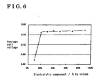
- the ratio of the electrolyte component is from 15 % to 100 % by volume relative to the reinforcement layer of 100 % by volume, an average cell voltage was kept to be high.
- the ratio of the electrolyte component becomes less than 15 % by volume, as the ratio of the electrolyte component decreases, the average cell voltage tends to drastically decrease.
- the ratio of the electrolyte component be from 15 % to 85 % by volume, in particular, be from 20 % to 80 % by volume relative to the reinforcement layer of 100 % by volume.
- the ratio of the microbodies be from 85 % to15 % by volume, in particular, be from 80 % to 20 % by volume relative to the reinforcement layer of 100 % by volume.
- the ratio of the microbodies can be from 20 % to 70 % by volume, from 30 % to 60 % by volume relative to the reinforcement layer of 100 % by volume.
- a material of the microbodies it is preferable that inorganic material having corrosion resistance and higher level of hardness than the electrolyte membrane be utilized.
- a material of the microbodies can be at least one of ceramics, carbon, and metal (including intermetallic compound).
- ceramics oxides, nitrides, carbides, borides, or the like, can be utilized.
- silica, alumina, silicon nitride, silicon carbide, zirconia, titanium carbide, titanium nitride, or the like can be exampled.
- Silica is preferable as oxides. Because silica has hydrophilicity, water-holding property of the microbodies can be expected.
- carbon carbon microparticles such as carbon black (including Acetylene Black, Ketjenblack) can be utilized.
- a surface of the microbodies can be smooth, or can have fine protruding portions and recessed portions.
- the fine protruding and recessed portions can contribute to ensure water-holding property of the microbodies. It is because that the amount of the surface area increases, and as a result, possibility of the microbodies to make contact with water can be raised, and capacity of the microbodies to hold water can therefore be enhanced.
- a particle size of the microbodies varies according to a thickness of the electrolyte membrane, requirement of resistance to sticking, requirement of resistance to gas permeability, pressing force during pressing, or the like. Generally, the particle size of the microbodies can be from 0.05 ⁇ m to 20 ⁇ m on average.
- the particle size of the microbodies can be from 0.1 ⁇ m to 10 ⁇ m, from 0.1 ⁇ m to 5 ⁇ m on average, furthermore, can be from 0.1 ⁇ m to 1 ⁇ m, from 0.2 ⁇ m to 0.8 ⁇ m.
- a shape of the microbodies can be particle-like shape, or a particulate fiber-like shape.
- a ratio of a major axis to a minor axis of the microbodies (a length of a major axis, considering a length of a minor axis as 1.0) can be from 1.0 to 1.5 as an example.
- a length of a diameter orthogonal to the predetermined direction can be from 0.5 to 1.5 as an example. Accordingly, the microbodies can have a spherical shape.
- the shape of the microbodies (not flocculated primary particles or secondary particles flocculated in some extent) be spherical in terms of increasing level of packing of the microbodies in the reinforcement layer, furthermore, for making gaps between the adjacent microbodies even in the case of high packing density.
- the gaps are advantageous to ensure ionic conductivity because of the electrolyte component existing between the gaps.
- spherical shape includes a spherical shape and a pseudo spherical shape.
- pie shape includes a shape having a ratio between a major axis and a minor axis of from 1.0 to 1.2, or a shape, considering a length of predetermined direction as 1.0, having a length of a diameter orthogonal to the predetermined direction of from 0.8 to 1.2.
- An average thickness of the reinforcement layer varies according to a particle size of the microbodies, required resistance to sticking, required resistance to gas permeability, a thickness of the electrolyte membrane, a thickness of a gas diffusion layer, or the like.
- the average thickness of the reinforcement layer can be, but not limited to, from 0.1 ⁇ m to 100 ⁇ m, in particular, from 1 ⁇ m to 20 ⁇ m.
- the reinforcement layer can be provided over the surface, onto which the gas diffusion layer is projected, of the electrolyte membrane. On occasion, the reinforcement layer can be provided locally at the surface, onto which the gas diffusion layer is projected, of the electrolyte membrane.
- a comparative example will be specifically explained.
- a dispersion manufactured by Daikin Industries, POLYFLON, Grade D1
- PTFE tetrafluoroethylene
- a carbon paper (manufactured by Toray, TORAYCA TGP-060, thickness: 180 ⁇ m) was thrown into the carbon ink for letting the carbon black and the PTFE, in other words, fluorocarbon polymers, contained in the carbon ink, infiltrate into the carbon paper.
- the carbon paper was put into a drying furnace maintained in a temperature condition of 80 °C for letting excess moisture contained in the carbon paper evaporate. After that, the carbon paper was maintained in a condition of sintering temperature of 390 °C for 60 minutes for sintering the PTFE. Thus, a water-repellent carbon paper was made.
- Carbon papers made as described above were utilized for the gas diffusion layer for fuel and the gas diffusion layer for oxidizing agent. As described above, because the gas diffusion layer for fuel and the gas diffusion layer for oxidizing agent are formed on the basis of carbon papers, there exists a danger that the carbon fibers (electrically conductive fibers) forming the carbon paper sticks into the electrolyte membrane during a process of manufacturing the membrane electrode assembly.
- a carbon-supported platinum catalyst manufactured by Tanaka Kikinzoku Kogyo KK, TEC10E60E
- a carbon-supported platinum catalyst containing 55 wt % of platinum, 12 g, a solution of 5 wt % of ion-exchange resin (manufactured by Asahi Kasei Corporation, SS-1080), 106 g, water, 23 g, and as a forming helper agent, isopropyl alcohol, 23 g, were sufficiently mixed for making a catalyst paste.
- This catalyst paste was, for forming the catalyst layer for oxidizing agent, applied onto the surface of the gas diffusion layer for oxidizing agent by use of a doctor blade method.
- the catalyst paste was thus made and applied onto the surface of the gas diffusion layer for oxidizing agent so as to make the amount of platinum supported in the catalyst layer for oxidizing agent 0.8 mg/cm 2 . After that, the catalyst paste was dried. Thus, a gas diffusion electrode for oxidizing agent was formed.
- the catalyst paste described above was, for forming the catalyst layer for fuel, applied onto the surface of the gas diffusion layer for fuel by use of a doctor blade method.
- the catalyst paste was thus made and applied so as to making the amount of platinum supported in the catalyst layer for fuel 0.2 mg/cm 2 . After that, the catalyst paste was dried. Thus, a gas diffusion electrode for fuel was formed.
- An ion-exchange membrane (manufactured by DuPont Corporation, Nafion I12) having a thickness of 50 ⁇ m was utilized as the electrolyte membrane. Then, the gas diffusion electrode for oxidizing agent was arranged onto one surface of the electrolyte membrane. The gas diffusion electrode for fuel was arranged onto the other surface of the electrolyte membrane. After that, the arranged electrolyte membrane and the gas diffusion electrodes were hot-pressed in a condition of 140 °C in a temperature, 8 MPa in a pressure, for 3 minutes. Thus, a membrane electrode assembly (MEA) according to the comparative example was made.
- MEA membrane electrode assembly
- An electric cell was made by a process of assembling a gas distribution plate for fuel and a gas distribution plate for oxidizing agent with the MEA.
- electric generating operation was intermittently performed in a temperature condition of the cell of 75 °C.
- electricity was generated in a condition of 0.2 ampere/cm 2 for 3 minutes. After that, electric circuit was opened for 1 minute.
- an air utilization 40 %) was supplied to the gas diffusion electrode for oxidizing gas
- hydrogen gas utilization 90 % was supplied to the gas diffusion electrode for fuel.
- gas was supplied in a condition of atmospheric pressure.
- Table 1 represents an initial cell voltage, a cell voltage after 200 hours-intermittent operation test, an initial amount of cross leak of the cell, and the amount of cross leak of the cell after the 200 hours-intermittent operation test.
- silica microparticles of ceramics manufactured by Admatechs Co., Ltd., S0-E2 having a particle size of from 0.4 ⁇ m to 0.6 ⁇ m, 5 g, a solution of 5 wt % of ion-exchange resin (manufactured by Asahi Kasei Corporation, SS-910), 100 g, water, 20 g, and as a forming helper agent, isopropyl alcohol, 20g, were sufficiently mixed for making a silica paste.
- the silica paste was applied onto a tetrafluoroethylene sheet 10 by use of a doctor blade method for forming a reinforcement layer 11.
- the reinforcement layer 11 is formed from a mixture containing microbodies of silica as ceramics having resistance to sticking of carbon fibers and resistance to gas permeability and an electrolyte component containing an ion-exchange resin having proton conductivity.
- the silica microparticles (microbodies) described above have substantially spherical shape. In this case, the silica microparticle was mixed and applied so as to make the amount of silica particles supported in the reinforcement layer 11 per unit area to be 0.2 mg/cm 2 . Further, the reinforcement layer 11 was dried and becomes a silica sheet 12. In addition, an average thickness of the reinforcement layer 11 can be from 5 ⁇ m to10 ⁇ m.
- an electrolyte membrane 2 having a thickness of 50 ⁇ m, similar to that of the electrolyte membrane in the comparative example described above, was prepared.
- the silica sheet 12 described above was arranged onto the electrolyte membrane 2 so as to make contact of the reinforcement layer 11 with the electrolyte membrane 2.
- the silica sheet 12 and the electrolyte membrane 2 was hot-pressed in a condition of 150 °C in a temperature and 10 MPa in a pressure for 1 minute so as to print the reinforcement layer 11 onto the electrolyte membrane 2.
- a tetrafluoroethylene sheet 10 of the silica sheet 12 was detached from the silica sheet 12.
- a gas diffusion electrode 7 for oxidizing agent (electrode for oxidizing agent) and a gas diffusion electrode 8 for fuel (electrode for fuel), both as same electrodes as in the comparative examples, were prepared.
- a dispersion manufactured by Daikin Industries, POLYFLON, Grade D1
- PTFE tetrafluoroethylene
- fluorocarbon polymers 250 g
- a carbon paper manufactured by Toray, TORAYCA TGP-060, thickness: 180 ⁇ m
- the carbon paper was put into a drying furnace maintained in a temperature condition of 80 °C for letting excess moisture included in the carbon paper evaporate. After that, the carbon paper was maintained in a condition of sintering temperature of 390 °C for 60 minutes for sintering the PTFE.
- a water-repellent carbon paper was made.
- Carbon papers made as described above were utilized for the gas diffusion layer 3 for fuel and the gas diffusion layer 4 for oxidizing agent.
- the gas diffusion layer 3 for fuel and the gas diffusion layer 4 for oxidizing agent are formed from aggregation of carbon fibers as electrically conductive fibers. Carbon fibers are utilized, considering easiness of forming an electrically conductive path, corrosion resistance, and cost.
- a carbon-supported platinum catalyst manufactured by Tanaka Kikinzoku Kogyo KK, TEC10E60E
- a carbon-supported platinum catalyst containing 55 wt % of platinum, 12 g, a solution of 5 wt % of ion-exchange resin (manufactured by Asahi Kasei Corporation, SS-1080), 106g, water, 23g, and as a forming helper agent, isopropyl alcohol, 23g, were sufficiently mixed for making a catalyst paste.
- This catalyst paste was, for forming the catalyst layer 6 for oxidizing agent, applied onto the surface of the gas diffusion layer 4 for oxidizing agent by use of a doctor blade method.
- the catalyst paste was thus made and applied onto the surface of the gas diffusion layer 4 for oxidizing agent so as to make the amount of platinum supported in the catalyst layer for oxidizing agent 0.8 mg/cm 2 . After that, the catalyst paste was dried. Thus, a gas diffusion electrode 7 for oxidizing agent (electrode for oxidizing agent) was formed. Accordingly, the gas diffusion electrode 7 for oxidizing agent includes the gas diffusion layer 4 for oxidizing agent and the catalyst layer 6 for oxidizing agent.
- the catalyst paste described above was, for forming the catalyst layer 5 for fuel, applied onto the surface of the gas diffusion layer 3 for fuel by use of a doctor blade method.
- the catalyst paste was thus made and applied so as to making the amount of platinum supported in the catalyst layer 5 for fuel 0.2 mg/cm 2 .
- the catalyst paste was dried.
- a gas diffusion electrode 8 for fuel was formed.
- the gas diffusion electrode 8 for fuel includes the gas diffusion layer 3 for fuel and the catalyst layer 5 for fuel.
- the electrolyte membrane 2 was sandwiched by the gas diffusion electrode 7 for oxidizing agent (electrode for oxidizing agent) and the gas diffusion electrode 8 for fuel (electrode for fuel) so as to make contact of the catalyst layer 6 for oxidizing agent having been applied onto the gas diffusion electrode 7 for oxidizing agent with the reinforcement layer 11 of the electrolyte membrane 2 described above, and as to make contact of the catalyst layer 5 for fuel having been applied onto the gas diffusion electrode 8 for fuel with the opposite surface of the electrolyte membrane 2.
- the gas diffusion electrode 7 for oxidizing agent electrode for oxidizing agent
- the gas diffusion electrode 8 for fuel electrolyte for fuel
- the MEA 9 in other words, the membrane electrode assembly, includes the gas diffusion layer 3 for fuel, the catalyst layer 5 for fuel, the electrolyte membrane 2, the reinforcement layer 11, the catalyst layer 6 for oxidizing agent, and the gas diffusion layer 4 for oxidizing agent, arranged in an order described above in a thickness direction.
- an electric cell was made by a process of assembling a gas distribution plate 101 for fuel having a gas channel 101 a for fuel and a gas distribution plate 102 for oxidizing agent having a gas channel 102a for oxidizing agent with the MEA 9.
- the reinforcement layer 11 is provided on the surface of the electrolyte membrane 2, during a process of pressing, such as hot-press in a process of manufacturing, the carbon fibers (electrically conductive fibers) forming a base of the gas diffusion layer 3, 4 can be restrained from sticking into the electrolyte membrane 2. Accordingly, the technique described above according to the first example of the present invention is advantageous for increasing a level of durability of the electrolyte membrane 2, and furthermore, for extending a period of serving time of the electrolyte membrane 2.
- the reinforcement layer 11 contains the microparticles having resistance to gas permeability, the microparticles can have a function as a barrier for permeation of gases. Accordingly, reactive gases can be restrained from permeating through the electrolyte membrane 2 to the opposite electrode. Accordingly, the technique above described is advantageous for increasing a level of durability of the electrolyte membrane 2, and furthermore, for extending a period of serving time of the electrolyte membrane 2.
- the reinforcement layer 11 described above is made on the basis of silica, a level of thermal conductivity of the reinforcement layer 11 can be lower in comparison with that of the reinforcement layer 11 not containing silica.
- reaction of generating electricity occurred at the gas diffusion electrode 7 for oxidizing agent is accompanied by generation of heat.
- the generated heat it is preferable that the generated heat not be transmitted to the electrolyte membrane 2 that much.
- the reinforcement layer 11 is provided on the surface of the electrolyte membrane 2 so as to face the gas diffusion electrode 7 for oxidizing agent, it can be expected that the reinforcement layer 11 made on the basis of silica be effective for restraining the heat generated in a reaction of generating electricity from being transmitted to the electrolyte membrane 2. In this respect, increase in a level of durability of the electrolyte membrane 2 can be expected.
- a second example basically has a similar configuration to that of the first example. Differences from the first example will be mainly explained.
- the reinforcement layer 11 is provided so as to face the diffusion electrode 7 for fuel, which is substantially different from the first example. Then, the gas diffusion electrode 7 for oxidizing agent and the gas diffusion electrode 8 for fuel, as same as in the first example, were utilized. Further, as illustrated in Fig. 3A, the electrolyte membrane 2, having the reinforcement layer 11 having been applied onto one surface of the electrolyte membrane 2, was prepared. Then, as illustrated in Fig.
- the electrolyte membrane 2 was sandwiched by the gas diffusion electrode 7 for oxidizing agent and the gas diffusion electrode 8 for fuel so as to make contact of the catalyst layer 5 for fuel of the gas diffusion electrode 8 for fuel with the reinforcement layer 11 of the electrolyte membrane 2, and as to make contact of the catalyst layer 6 for oxidizing agent of the gas diffusion electrode 7 for oxidizing agent with the opposite surface of the electrolyte membrane 2.
- the electrolyte membrane 2 and the gas diffusion electrodes 7, 8 sandwiching the electrolyte membrane 2 were pressed in a condition of 140 °C in a temperature, 8 MPa in a pressure, for 3 minutes.
- MEA membrane electrode assembly
- An electric cell was made by a process of assembling a gas distribution plate 101 for fuel and a gas distribution plate 102 for oxidizing agent with the MEA 9 in the same way as in the comparative example.
- the electric cell was evaluated in the same way as in the comparative example.
- Table 1 represents the results of the evaluation.
- a third example basically has a similar configuration to that of the first example. Differences from the first example will be mainly explained.
- the silica sheets 12 and the electrolyte membrane 2 were arranged so as to make contact of the reinforcement layers 11 with the both surfaces of the electrolyte membrane 2.
- the silica sheets 12 and the electrolyte membrane 2 were hot-pressed in a condition of 150 °C in a temperature, 10 MPa in a pressure, for 1 minute.
- the reinforcement layers 11 were printed onto both surfaces of the electrolyte membrane 2.
- sheets 10 of the silica sheets 12 were detached. Accordingly, as illustrated in Fig.
- a fourth example basically has a similar configuration to that of the first example. Differences from the first example will be mainly explained.
- two electrolyte membranes 2a, 2b manufactured by DuPont, Nafion 111 of 25 ⁇ m of thickness were prepared.
- a reinforcement layer 11 was printed onto one surface of an electrolyte membrane 2a.
- an electrolyte membrane 2b was arranged onto the reinforcement layer 11.
- the electrolyte membranes 2a, 2b and the reinforcement layer 11 were hot-pressed in a condition of 150 °C in a temperature, 10 MPa in a pressure, for 1 minute.
- the two electrolyte membranes were bonded each other across the reinforcement layer 11, and thus an electrolyte membrane 2X was made (Please refer to Fig. 5B).
- a gas diffusion electrode 7 for oxidizing agent and a gas diffusion electrode 8 for fuel similar electrodes as in the comparative example, were prepared.
- the electrolyte membrane 2X was sandwiched in thickness direction by the gas diffusion electrode 7 for oxidizing agent and the gas diffusion electrode 8 for fuel so as to make contact of the electrolyte membrane 2b of the electrolyte membrane 2X with the catalyst layer 5 for fuel, and as to make contact of the electrolyte membrane 2a of the electrolyte membrane 2X with the catalyst layer 6 for oxidizing agent.
- the reinforcement layer 11 is provided inside the electrolyte membrane 2X, during a process of pressing such as a hot-press in the manufacturing process, the carbon fibers (electrically conductive fibers) can be restrained from sticking through the electrolyte membrane 2, and the reaction gases can be restrained from permeating through the electrolyte membrane 2X.
- the MEA 9 was evaluated in the same way as in the comparative example. Table 1 represents the results of the evaluation.
- a fifth example basically has a similar configuration to that of the first example.
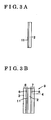
- Fig. 1A to 1C and Fig. 2A to 2C will be applied correspondingly. Differences from the first example will be mainly explained.
- carbon black was utilized instead of silica.
- carbon black (Ketjenblack) 5 g
- a solution of 5 wt % of ion-exchange resin manufactured by Asahi Kasei Corporation, SS-910
- 100g water, 20g
- isopropyl alcohol, 20g were sufficiently mixed.
- a carbon black paste was made.
- This carbon black paste was applied onto a sheet 10 by use of a doctor blade method for forming a reinforcement layer 15 formed from the carbon black so as to make the amount of the supported carbon black in the reinforcement layer 15 to be 0.2 mg/cm 2 . After that, the reinforcement layer 15 was dried and becomes a carbon black sheet 16.
- the reinforcement layer 15 contains the carbon black serving as the microbodies having resistance to sticking by carbon fibers, and the electrolyte component containing the ion-exchange resin having proton-conductivity.
- an average thickness of the reinforcement layer 15 can be within a range of from 5 ⁇ m to 10 ⁇ m.
- an electrolyte membrane 2 of 50 ⁇ m in thickness, similar to that utilized in the comparative example, and the reinforcement layer 15 were arranged so as to make contact of the reinforcement layer 15 with one surface of the electrolyte membrane 2.
- the carbon black sheet 16 and the electrolyte membrane 2 was hot-pressed in a condition of 150 °C in a temperature, 10 MPa in a pressure, for 1 minute.
- the reinforcement layer 15 was printed onto the electrolyte membrane 2. After that, the sheet 10 was detached.
- a gas diffusion electrode 7 for oxidizing agent and a gas diffusion electrode 8 for fuel both as same electrodes as in the comparative examples, were prepared.
- the electrolyte membrane 2 was sandwiched in a thickness direction by the gas diffusion electrode 7 for oxidizing agent (electrode for oxidizing agent) and the gas diffusion electrode 8 for fuel (electrode for fuel) so as to make contact of the catalyst layer 6 for oxidizing agent of the gas diffusion electrode 7 for oxidizing agent with the reinforcement layer 15 of the electrolyte membrane 2 described above, and as to make contact of the catalyst layer 5 for fuel of the gas diffusion electrode 8 for fuel with the opposite surface of the electrolyte membrane 2.
- polymer electrolyte fuel cells according to from the first to fifth examples exhibited high cell voltage after the test, and substantially small amount of leak of gas after the test. In particular, in the fourth example, the amount of leak of gas was smallest. As described above, the polymer electrolyte fuel cells according to from the first to fifth examples were found to be superior in output of cell voltage and resistance to leak of gas.
- Fig. 6 represents the results of the investigation. As illustrated in Fig. 6, when a ratio of the electrolyte component is from 20 % to 100 % by volume relative to the reinforcement layer 11 of 100 % by volume, average cell voltages were high. However, when the ratio of the electrolyte component is equal to 10 % by volume relative to the reinforcement layer 11 of 100 % by volume, an average cell voltage tended to be sharply lowered.
- the ratio of the electrolyte component be 15 % by volume or higher, be 20 % by volume or higher, relative to the reinforcement layer of 100 %.
- the ratio of the contained microbodies becomes excessively high, because the ratio of the contained electrolyte component becomes low, there is a danger that a level of proton conductivity becomes low.
- the ratio of the contained microbodies be 85 % by volume or lower, be 80 % by volume or lower.
- a ratio of the microbodies be 15 % by volume or higher, 20 % by volume or higher relative to the 100 % by volume of the reinforcement layer. Accordingly, it is preferable that the ratio of the electrolyte component be from 15 % to 85 % by volume, be from 20 % to 80 % by volume relative to the reinforcement layer of 100 % by volume, and it is preferable that the ratio of the contained microbodies such as silica be from 85 % to 15 % by volume, be from 80 % to 20 % by volume to the reinforcement layer of 100 % by volume.
- a shape of silica microparticles is substantially spherical.
- a shape of silica microparticles is not limited.
- a shape of the silica microparticles can also be non-spherical shape, such as elliptical shape, polyhedral shape, or some other shapes.
- variations can be implemented without deviating from the content of the present invention. Following technical concepts can be construed from the above.
- a membrane electrode assembly formed by arranging an electrode for fuel, an electrolyte membrane, an electrode for oxidizing agent in an order described above is characterized in that a reinforcement layer, containing a plurality of microbodies having at least either one of resistance to gas permeability and resistance to sticking and an electrolyte component having ionic conductivity, is provided between at least either one of the electrode for fuel and the electrode for oxidizing agent and the electrolyte membrane, or is provided inside the electrolyte membrane.
- a polymer electrolyte fuel cell including a membrane electrode assembly formed by arranging an electrode for fuel, an electrolyte membrane, an electrode for oxidizing agent in an order described above is characterized in that a reinforcement layer, containing a plurality of microbodies having at least either one of resistance to gas permeability and resistance to sticking and an electrolyte component having ionic conductivity, is provided between at least either one of the electrode for fuel and the electrode for oxidizing agent and the electrolyte membrane, or is provided inside the electrolyte membrane.
- an inventor of the present invention has been engaged in development of a membrane electrode assembly for long years.
- the inventor found and confirmed advantages of providing a reinforcement layer between at least either one of a diffusion layer for fuel and a diffusion layer for oxidizing agent and an electrolyte membrane, or inside the electrolyte membrane in terms of restraining electrically conductive fibers from sticking into the electrolyte membrane, which therefore leads to further advantages for restraining reactive gases from permeating through the electrolyte membrane.
- the inventor of the present invention found and confirms advantages of providing a reinforcement layer containing a plurality of microbodies having resistance to gas permeability and an electrolyte component having ionic conductivity between at least either one of a gas diffusion layer for fuel and a gas diffusion layer for oxidizing agent and an electrolyte membrane, or inside the electrolyte membrane in terms of restraining reaction gases from permeating through the electrolyte membrane.
- the reason why effects described above are obtained can be assumed that the reinforcement layer containing a plurality of microbodies which restrains reactive gases from permeating is present, thus permeation of reactive gases through the electrolyte membrane is restrained, and the permeation of reaction gases to the opposite side of the electrode can therefore be restrained.
- a membrane electrode assembly is formed by arranging a gas diffusion layer for fuel on the basis of electrically conductive fibers, a catalyst layer for fuel, an electrolyte membrane, a catalyst layer for oxidizing agent, and a gas diffusion layer for oxidizing agent on the basis of electrically conductive fibers in an order described above.
- a reinforcement layer for restraining the electrically conductive fibers from sticking into the electrolyte membrane is provided between at least either one of the gas diffusion layer for fuel and the gas diffusion layer for oxidizing agent and the electrolyte membrane, or is provided inside the electrolyte membrane.
- a polymer electrolyte fuel cell includes a membrane electrode assembly formed by arranging a gas diffusion layer for fuel made on the basis of electrically conductive fibers, a catalyst layer for fuel, an electrolyte membrane, a catalyst layer for oxidizing agent, and a gas diffusion layer for oxidizing agent made on the basis of electrically conductive fibers in an order described above.
- a reinforcement layer for restraining the electrically conductive fibers from sticking into the electrolyte membrane is provided between at least either one of the gas diffusion layer for fuel and the gas diffusion layer for oxidizing agent and the electrolyte membrane, or is provided inside the electrolyte membrane.
- sticking by the electrically conductive fibers such as carbon fibers which are a base of the gas diffusion layer into the electrolyte membrane can be restrained, and permeation of gases through the traces of sticking can be restrained.
- a membrane electrode assembly is formed by arranging an electrode for fuel, an electrolyte membrane, an electrode for oxidizing agent in an order described above.
- a reinforcement layer containing a plurality of microbodies having resistance to gas permeability and an electrolyte component having ionic conductivity is provided between, on the one hand, at least either one of the electrode for fuel and the electrode for oxidizing agent, on the other hand, the electrolyte membrane, or is provided inside the electrolyte membrane.
- a polymer electrolyte fuel cell includes a membrane electrode assembly formed by arranging an electrode for fuel, an electrolyte membrane, and an electrode for oxidizing agent in an order described above.
- a reinforcement layer containing a plurality of microbodies having resistance to gas permeability and an electrolyte component having ionic conductivity is provided between at least either one of the electrode for fuel and the electrode for oxidizing agent and the electrolyte membrane, or is provided inside the electrolyte membrane.
- the present invention can be utilized for a polymer electrolyte fuel cell employed in equipment for generating electricity for a vehicle.
- the present invention can also be utilized for stationary or mobile polymer electrolyte fuel cell.
- a membrane electrode assembly (9) is formed by arranging a gas diffusion layer (3) for fuel made on the basis of electrically conductive fibers, a catalyst layer (5) for fuel, an electrolyte membrane (2), a catalyst layer (6) for oxidizing agent, and a gas diffusion layer (4) for oxidizing agent made on the basis of electrically conductive fibers in an order described above.
- the membrane electrode assembly is characterized in that a reinforcement layer (11) for restraining the electrically conductive fibers from sticking into the electrolyte membrane is provided between at least either one of the gas diffusion layer for fuel and the gas diffusion layer for oxidizing agent and the electrolyte membrane, or is provided inside the electrolyte membrane.
Landscapes
- Life Sciences & Earth Sciences (AREA)
- Engineering & Computer Science (AREA)
- Manufacturing & Machinery (AREA)
- Sustainable Development (AREA)
- Sustainable Energy (AREA)
- Chemical & Material Sciences (AREA)
- Chemical Kinetics & Catalysis (AREA)
- Electrochemistry (AREA)
- General Chemical & Material Sciences (AREA)
- Fuel Cell (AREA)
- Inert Electrodes (AREA)
Abstract
Description
| Comparative example | First example | Second example | Third example | Fourth example | Fifth example | |
| Initial cell voltage V, 0.2 A/cm2 | 0.769 | 0.766 | 0.767 | 0.768 | 0.765 | 0.767 |
| Cell voltage after test V, 0.2 A/cm2 | 0.721 | 0.746 | 0.743 | 0.740 | 0.750 | 0.741 |
| Initial cross leak of cell Kpa, 5min × 20 | 0 | 0 | 0 | 0 | 0 | 0 |
| Cell cross leak after test Kpa, 5min × 20 KPa | 1.34 | 0.11 | 0.14 | 0.18 | 0.06 | 0.13 |
Claims (8)
- A membrane electrode assembly (9) formed by arranging a gas diffusion layer (3) for fuel made on the basis of electrically conductive fibers, a catalyst layer (5) for fuel, an electrolyte membrane (2), a catalyst layer (6) for oxidizing agent, and a gas diffusion layer (4) for oxidizing agent made on the basis of electrically conductive fibers in an order described above characterized in that
a reinforcement layer (11) for restraining the electrically conductive fibers from sticking into the electrolyte membrane is provided between at least either one of the gas diffusion layer for fuel and the gas diffusion layer for oxidizing agent and the electrolyte membrane, or is provided inside the electrolyte membrane. - The membrane electrode assembly according to claim 1, wherein
the reinforcement layer contains a plurality of microbodies having resistance to sticking and an electrolyte component having ionic conductivity. - A membrane electrode assembly (9) formed by arranging an electrode (8) for fuel, an electrolyte membrane (2), and an electrode (7) for oxidizing agent in an order described above characterized in that
a reinforcement layer (11) containing a plurality of microbodies having resistance to gas permeability and an electrolyte component having ionic conductivity is provided between at least either one of the electrode for fuel and the electrode for oxidizing agent and the electrolyte membrane, or is provided inside the electrolyte membrane. - The membrane electrode assembly according to either one of claims 2 and 3, wherein the plurality of microbodies are made of inorganic substance.
- The membrane electrode assembly according to claim 4, wherein
the plurality of microbodies include at least one of ceramics, carbon microparticles, and metal. - The membrane electrode assembly according to any one of claims 2 to 5, wherein an average particle size of the plurality of microbodies is from 0.05 µm to 20 µm.
- A polymer electrolyte fuel cell, comprising:a membrane electrode assembly (9) formed by arranging a gas diffusion layer (3) for fuel made on the basis of electrically conductive fibers, a catalyst layer (5) for fuel, an electrolyte membrane (2), a catalyst layer (6) for oxidizing agent, and a gas diffusion layer (4) for oxidizing agent made on the basis of electrically conductive fibers in an order described above characterized in thata reinforcement layer (11) for restraining the electrically conductive fibers fromsticking into the electrolyte membrane is provided between at least either one of the gas diffusion layer for fuel and the gas diffusion layer for oxidizing agent and theelectrolyte membrane, or is provided inside the electrolyte membrane.
- A polymer electrolyte fuel cell, comprising:a membrane electrode assembly (9) formed by arranging an electrode (8) for fuel, an electrolyte membrane (2), and an electrode (7) for oxidizing agent in an order described above characterized in thata reinforcement layer (11) containing a plurality of microbodies having resistance togas permeability and an electrolyte component having ionic conductivity is provided between at least either one of the electrode for fuel and the electrode for oxidizing agent and the electrolyte membrane, or is provided inside the electrolyte membrane.
Applications Claiming Priority (2)
| Application Number | Priority Date | Filing Date | Title |
|---|---|---|---|
| JP2004149450 | 2004-05-19 | ||
| JP2004149450A JP2005332672A (en) | 2004-05-19 | 2004-05-19 | Membrane electrode assembly, polymer electrolyte fuel cell |
Publications (2)
| Publication Number | Publication Date |
|---|---|
| EP1598890A2 true EP1598890A2 (en) | 2005-11-23 |
| EP1598890A3 EP1598890A3 (en) | 2006-01-04 |
Family
ID=34936149
Family Applications (1)
| Application Number | Title | Priority Date | Filing Date |
|---|---|---|---|
| EP05009795A Withdrawn EP1598890A3 (en) | 2004-05-19 | 2005-05-04 | Membrane electrode assembly |
Country Status (3)
| Country | Link |
|---|---|
| US (1) | US20050260476A1 (en) |
| EP (1) | EP1598890A3 (en) |
| JP (1) | JP2005332672A (en) |
Cited By (2)
| Publication number | Priority date | Publication date | Assignee | Title |
|---|---|---|---|---|
| WO2009151013A1 (en) * | 2008-06-09 | 2009-12-17 | 旭硝子株式会社 | Membrane electrode assembly for polymer fuel cell |
| US8241821B2 (en) | 2008-09-05 | 2012-08-14 | Asahi Glass Company, Limited | Reflective mask blank for EUV lithography, process for producing the same and mask for EUV lithography |
Families Citing this family (13)
| Publication number | Priority date | Publication date | Assignee | Title |
|---|---|---|---|---|
| US7943268B2 (en) * | 2005-10-04 | 2011-05-17 | GM Global Technology Operations LLC | Reinforced membrane electrode assembly |
| CN101416342B (en) * | 2006-04-07 | 2011-10-19 | Utc电力公司 | Composite water management electrolytes film for fuel battery |
| JP4815460B2 (en) | 2008-03-13 | 2011-11-16 | 株式会社日立製作所 | Membrane / electrode assembly for fuel cells |
| KR101617253B1 (en) * | 2011-11-04 | 2016-05-02 | 도요타 지도샤(주) | Fuel cell membrane-electrode assembly |
| US20120141910A1 (en) * | 2012-02-10 | 2012-06-07 | Clearedge Power, Inc. | Multiple Membrane Layers in a Fuel Cell Membrane-Electrode Assembly |
| JP6007163B2 (en) | 2012-11-22 | 2016-10-12 | 本田技研工業株式会社 | Electrolyte membrane / electrode structure |
| JP5829203B2 (en) | 2012-12-03 | 2015-12-09 | 本田技研工業株式会社 | Fuel cell |
| JP6356436B2 (en) | 2013-03-26 | 2018-07-11 | 本田技研工業株式会社 | Electrolyte membrane / electrode structure |
| JP6131973B2 (en) | 2014-03-14 | 2017-05-24 | トヨタ自動車株式会社 | Method for producing reinforced electrolyte membrane, method for producing membrane electrode assembly, and membrane electrode assembly |
| WO2016154198A1 (en) * | 2015-03-24 | 2016-09-29 | Bloom Energy Corporation | Perimeter electrolyte reinforcement layer composition for solid oxide fuel cell electrolytes |
| WO2017090860A1 (en) * | 2015-11-26 | 2017-06-01 | 주식회사 엘지화학 | Polymer electrolyte membrane, membrane electrode assembly comprising same, and fuel cell comprising membrane electrode assembly |
| KR102093536B1 (en) | 2015-11-26 | 2020-03-25 | 주식회사 엘지화학 | Polymer electrolyte membrane, membrane electrode assembly comprising the same and fuel cell comprising the membrane electrode assembly |
| KR102467811B1 (en) * | 2020-11-25 | 2022-11-16 | 비나텍주식회사 | Membrane-electrode assembly manufacturing method for fuel cell with reinforced layer |
Family Cites Families (14)
| Publication number | Priority date | Publication date | Assignee | Title |
|---|---|---|---|---|
| US3977901A (en) * | 1974-10-23 | 1976-08-31 | Westinghouse Electric Corporation | Metal/air cells and improved air electrodes for use therein |
| US5547551A (en) * | 1995-03-15 | 1996-08-20 | W. L. Gore & Associates, Inc. | Ultra-thin integral composite membrane |
| JPH09265992A (en) * | 1996-03-29 | 1997-10-07 | Mazda Motor Corp | Fuel cell electrode structure |
| US5981097A (en) * | 1996-12-23 | 1999-11-09 | E.I. Du Pont De Nemours And Company | Multiple layer membranes for fuel cells employing direct feed fuels |
| AU4500500A (en) * | 1999-04-30 | 2000-11-17 | University Of Connecticut, The | Membranes, membrane electrode assemblies and fuel cells employing same, and process for preparing |
| US6517962B1 (en) * | 1999-08-23 | 2003-02-11 | Ballard Power Systems Inc. | Fuel cell anode structures for voltage reversal tolerance |
| JP2002008678A (en) * | 2000-06-16 | 2002-01-11 | Asahi Glass Co Ltd | Polymer electrolyte fuel cell |
| JP4721500B2 (en) * | 2000-09-28 | 2011-07-13 | 京セラ株式会社 | Solid oxide fuel cell and method for producing the same |
| JP2003059511A (en) * | 2001-08-17 | 2003-02-28 | Matsushita Electric Ind Co Ltd | Electrolyte membrane-electrode assembly for fuel cell, method for producing the same, and polymer electrolyte fuel cell |
| US6613203B1 (en) * | 2001-09-10 | 2003-09-02 | Gore Enterprise Holdings | Ion conducting membrane having high hardness and dimensional stability |
| JP2003151577A (en) * | 2001-11-12 | 2003-05-23 | Sanyo Electric Co Ltd | Fuel-cell cell unit |
| JP2003282093A (en) * | 2002-03-25 | 2003-10-03 | Matsushita Electric Ind Co Ltd | Electrolyte membrane-electrode assembly for fuel cell and method for producing the same |
| US6861173B2 (en) * | 2002-10-08 | 2005-03-01 | Sompalli Bhaskar | Catalyst layer edge protection for enhanced MEA durability in PEM fuel cells |
| JP2004220843A (en) * | 2003-01-10 | 2004-08-05 | Toyota Central Res & Dev Lab Inc | Membrane electrode assembly |
-
2004
- 2004-05-19 JP JP2004149450A patent/JP2005332672A/en active Pending
-
2005
- 2005-05-03 US US11/119,922 patent/US20050260476A1/en not_active Abandoned
- 2005-05-04 EP EP05009795A patent/EP1598890A3/en not_active Withdrawn
Cited By (3)
| Publication number | Priority date | Publication date | Assignee | Title |
|---|---|---|---|---|
| WO2009151013A1 (en) * | 2008-06-09 | 2009-12-17 | 旭硝子株式会社 | Membrane electrode assembly for polymer fuel cell |
| US8535847B2 (en) | 2008-06-09 | 2013-09-17 | Asahi Glass Company, Limited | Membrane/electrode assembly for polymer electrolyte fuel cell |
| US8241821B2 (en) | 2008-09-05 | 2012-08-14 | Asahi Glass Company, Limited | Reflective mask blank for EUV lithography, process for producing the same and mask for EUV lithography |
Also Published As
| Publication number | Publication date |
|---|---|
| US20050260476A1 (en) | 2005-11-24 |
| EP1598890A3 (en) | 2006-01-04 |
| JP2005332672A (en) | 2005-12-02 |
Similar Documents
| Publication | Publication Date | Title |
|---|---|---|
| US5620807A (en) | Flow field assembly for electrochemical fuel cells | |
| CN101027807B (en) | Membrane electrode assembly | |
| US20050260476A1 (en) | Membrane electrode assembly | |
| US20090068525A1 (en) | Fuel Cell Electrode, Method for Producing Fuel Cell Electrode, Membrane-Electrode Assembly, Method for Producing Membrane-Electrode Assembly, and Solid Polymer Fuel Cell | |
| JP2008508679A (en) | End-protected catalyst-coated diffusion medium and membrane electrode assembly | |
| CN103534852A (en) | Gas diffusion layer for fuel cell and method for producing same | |
| JP4133654B2 (en) | Polymer electrolyte fuel cell | |
| JP3459615B2 (en) | Electrode for fuel cell and fuel cell | |
| US8568942B2 (en) | Gas diffusion electrode, method for manufacturing the same and membrane electrode assembly | |
| EP1429408A1 (en) | Electrolyte membrane/electrode union for fuel cell and process for producing the same | |
| US6946214B2 (en) | Manufacturing method of fuel cell electrode and fuel cell using thereof | |
| JP4901748B2 (en) | Gas diffusion media with microporous bilayer | |
| JP2010073586A (en) | Electrolyte membrane-electrode assembly | |
| EP1383184A1 (en) | Electrode for fuel cell and method of manufacturing the electrode | |
| JP2004220843A (en) | Membrane electrode assembly | |
| JP5034172B2 (en) | Gas diffusion layer for fuel cell and fuel cell using the same | |
| JP4612569B2 (en) | Membrane electrode structure for polymer electrolyte fuel cell | |
| KR101542194B1 (en) | Membrane Electrode Assembly for Fuel Cell, Method of Manufacturing the Same, and Fuel Cell Including the Same | |
| EP2555303A1 (en) | Bonding material for fuel cell, and fuel cell | |
| US20030008195A1 (en) | Fluid diffusion layers for fuel cells | |
| JP2004158387A (en) | Electrode structure for polymer electrolyte fuel cell | |
| JP4338491B2 (en) | Method for producing gas diffusion layer for polymer electrolyte fuel cell | |
| KR101326190B1 (en) | Membrane Electrode Assembly for fuel cell and fuel cell using the same | |
| JP2005216834A (en) | Polymer electrolyte fuel cell | |
| JP2006085984A (en) | MEA for fuel cell and fuel cell using the same |
Legal Events
| Date | Code | Title | Description |
|---|---|---|---|
| PUAI | Public reference made under article 153(3) epc to a published international application that has entered the european phase |
Free format text: ORIGINAL CODE: 0009012 |
|
| PUAL | Search report despatched |
Free format text: ORIGINAL CODE: 0009013 |
|
| AK | Designated contracting states |
Kind code of ref document: A2 Designated state(s): AT BE BG CH CY CZ DE DK EE ES FI FR GB GR HU IE IS IT LI LT LU MC NL PL PT RO SE SI SK TR |
|
| AX | Request for extension of the european patent |
Extension state: AL BA HR LV MK YU |
|
| AK | Designated contracting states |
Kind code of ref document: A3 Designated state(s): AT BE BG CH CY CZ DE DK EE ES FI FR GB GR HU IE IS IT LI LT LU MC NL PL PT RO SE SI SK TR |
|
| AX | Request for extension of the european patent |
Extension state: AL BA HR LV MK YU |
|
| 17P | Request for examination filed |
Effective date: 20060329 |
|
| AKX | Designation fees paid |
Designated state(s): DE GB |
|
| 17Q | First examination report despatched |
Effective date: 20061227 |
|
| STAA | Information on the status of an ep patent application or granted ep patent |
Free format text: STATUS: THE APPLICATION IS DEEMED TO BE WITHDRAWN |
|
| 18D | Application deemed to be withdrawn |
Effective date: 20110315 |