EP1598813A1 - Moyen d'enregistrement magnétique et dispositif magnétique de stockage - Google Patents
Moyen d'enregistrement magnétique et dispositif magnétique de stockage Download PDFInfo
- Publication number
- EP1598813A1 EP1598813A1 EP05017215A EP05017215A EP1598813A1 EP 1598813 A1 EP1598813 A1 EP 1598813A1 EP 05017215 A EP05017215 A EP 05017215A EP 05017215 A EP05017215 A EP 05017215A EP 1598813 A1 EP1598813 A1 EP 1598813A1
- Authority
- EP
- European Patent Office
- Prior art keywords
- layer
- magnetic
- recording medium
- magnetic recording
- thickness
- Prior art date
- Legal status (The legal status is an assumption and is not a legal conclusion. Google has not performed a legal analysis and makes no representation as to the accuracy of the status listed.)
- Withdrawn
Links
- 230000005291 magnetic effect Effects 0.000 title claims abstract description 196
- 238000003860 storage Methods 0.000 title claims description 18
- 230000008878 coupling Effects 0.000 claims abstract description 40
- 238000010168 coupling process Methods 0.000 claims abstract description 40
- 238000005859 coupling reaction Methods 0.000 claims abstract description 40
- 230000005415 magnetization Effects 0.000 claims abstract description 31
- 239000003302 ferromagnetic material Substances 0.000 claims abstract description 3
- 230000005294 ferromagnetic effect Effects 0.000 claims description 38
- 239000000463 material Substances 0.000 claims description 15
- 229910045601 alloy Inorganic materials 0.000 claims description 11
- 239000000956 alloy Substances 0.000 claims description 11
- 229910052802 copper Inorganic materials 0.000 claims description 8
- 229910019222 CoCrPt Inorganic materials 0.000 claims description 7
- 229910052750 molybdenum Inorganic materials 0.000 claims description 6
- 229910052758 niobium Inorganic materials 0.000 claims description 6
- 229910052715 tantalum Inorganic materials 0.000 claims description 6
- 229910052721 tungsten Inorganic materials 0.000 claims description 6
- 229910000599 Cr alloy Inorganic materials 0.000 claims description 5
- 229910052796 boron Inorganic materials 0.000 claims description 5
- 229910001149 41xx steel Inorganic materials 0.000 claims description 3
- 230000005293 ferrimagnetic effect Effects 0.000 abstract description 11
- 230000006870 function Effects 0.000 abstract description 4
- 239000010410 layer Substances 0.000 description 197
- 239000000758 substrate Substances 0.000 description 16
- 229910000531 Co alloy Inorganic materials 0.000 description 14
- 238000010586 diagram Methods 0.000 description 14
- 238000000034 method Methods 0.000 description 13
- 230000000694 effects Effects 0.000 description 9
- 239000010952 cobalt-chrome Substances 0.000 description 8
- 230000008569 process Effects 0.000 description 8
- 229910018979 CoPt Inorganic materials 0.000 description 7
- 230000002411 adverse Effects 0.000 description 5
- 239000011521 glass Substances 0.000 description 5
- 230000001965 increasing effect Effects 0.000 description 5
- 239000011241 protective layer Substances 0.000 description 5
- 229910052703 rhodium Inorganic materials 0.000 description 5
- 229910052707 ruthenium Inorganic materials 0.000 description 5
- 229910052742 iron Inorganic materials 0.000 description 4
- 239000000314 lubricant Substances 0.000 description 4
- 229910052759 nickel Inorganic materials 0.000 description 4
- -1 CoCrTa Inorganic materials 0.000 description 3
- 229910000640 Fe alloy Inorganic materials 0.000 description 3
- 229910000990 Ni alloy Inorganic materials 0.000 description 3
- 229910052741 iridium Inorganic materials 0.000 description 3
- 239000000203 mixture Substances 0.000 description 3
- 230000003647 oxidation Effects 0.000 description 3
- 238000007254 oxidation reaction Methods 0.000 description 3
- 230000002829 reductive effect Effects 0.000 description 3
- 229910000943 NiAl Inorganic materials 0.000 description 2
- NPXOKRUENSOPAO-UHFFFAOYSA-N Raney nickel Chemical compound [Al].[Ni] NPXOKRUENSOPAO-UHFFFAOYSA-N 0.000 description 2
- 238000006243 chemical reaction Methods 0.000 description 2
- 229910052804 chromium Inorganic materials 0.000 description 2
- 238000010276 construction Methods 0.000 description 2
- 238000009826 distribution Methods 0.000 description 2
- 230000006872 improvement Effects 0.000 description 2
- 230000009467 reduction Effects 0.000 description 2
- 238000004088 simulation Methods 0.000 description 2
- 239000000725 suspension Substances 0.000 description 2
- 229910052723 transition metal Inorganic materials 0.000 description 2
- 150000003624 transition metals Chemical class 0.000 description 2
- 229910000838 Al alloy Inorganic materials 0.000 description 1
- 229910000684 Cobalt-chrome Inorganic materials 0.000 description 1
- 229910000575 Ir alloy Inorganic materials 0.000 description 1
- 229910000629 Rh alloy Inorganic materials 0.000 description 1
- 229910000929 Ru alloy Inorganic materials 0.000 description 1
- 230000008859 change Effects 0.000 description 1
- 238000004140 cleaning Methods 0.000 description 1
- 230000003247 decreasing effect Effects 0.000 description 1
- 230000006866 deterioration Effects 0.000 description 1
- 238000010438 heat treatment Methods 0.000 description 1
- 230000001939 inductive effect Effects 0.000 description 1
- 230000003993 interaction Effects 0.000 description 1
- 239000011229 interlayer Substances 0.000 description 1
- 238000002955 isolation Methods 0.000 description 1
- 238000001755 magnetron sputter deposition Methods 0.000 description 1
- 238000004519 manufacturing process Methods 0.000 description 1
- 230000004048 modification Effects 0.000 description 1
- 238000012986 modification Methods 0.000 description 1
- 230000010355 oscillation Effects 0.000 description 1
- 230000001737 promoting effect Effects 0.000 description 1
- 230000002441 reversible effect Effects 0.000 description 1
- 238000005204 segregation Methods 0.000 description 1
- 239000002356 single layer Substances 0.000 description 1
- 230000009897 systematic effect Effects 0.000 description 1
- 238000007725 thermal activation Methods 0.000 description 1
- 239000010409 thin film Substances 0.000 description 1
- 230000007704 transition Effects 0.000 description 1
Images


Classifications
-
- G—PHYSICS
- G11—INFORMATION STORAGE
- G11B—INFORMATION STORAGE BASED ON RELATIVE MOVEMENT BETWEEN RECORD CARRIER AND TRANSDUCER
- G11B5/00—Recording by magnetisation or demagnetisation of a record carrier; Reproducing by magnetic means; Record carriers therefor
- G11B5/62—Record carriers characterised by the selection of the material
- G11B5/64—Record carriers characterised by the selection of the material comprising only the magnetic material without bonding agent
- G11B5/66—Record carriers characterised by the selection of the material comprising only the magnetic material without bonding agent the record carriers consisting of several layers
- G11B5/676—Record carriers characterised by the selection of the material comprising only the magnetic material without bonding agent the record carriers consisting of several layers having magnetic layers separated by a nonmagnetic layer, e.g. antiferromagnetic layer, Cu layer or coupling layer
-
- G—PHYSICS
- G11—INFORMATION STORAGE
- G11B—INFORMATION STORAGE BASED ON RELATIVE MOVEMENT BETWEEN RECORD CARRIER AND TRANSDUCER
- G11B5/00—Recording by magnetisation or demagnetisation of a record carrier; Reproducing by magnetic means; Record carriers therefor
- G11B5/62—Record carriers characterised by the selection of the material
- G11B5/73—Base layers, i.e. all non-magnetic layers lying under a lowermost magnetic recording layer, e.g. including any non-magnetic layer in between a first magnetic recording layer and either an underlying substrate or a soft magnetic underlayer
- G11B5/7368—Non-polymeric layer under the lowermost magnetic recording layer
- G11B5/7373—Non-magnetic single underlayer comprising chromium
Definitions
- the present invention generally relates to magnetic recording media and magnetic storage apparatuses, and more particularly to a magnetic recording medium and a magnetic storage apparatus which are suited for high-density recording.
- a typical magnetic recording medium has a stacked structure having a substrate, an underlayer, a magnetic layer and a protective layer which are stacked in this sequence.
- the underlayer is made of Cr or a Cr alloy
- the magnetic layer is made of a Co alloy.
- the underlayers described above promote in-plane orientation of the magnetic layer and increase the residual magnetization and the thermal stability of bits.
- Proposals have also been made to reduce the thickness of the magnetic layer to increase the resolution or, to reduce the transition width between the written bits.
- a proposal has also been made to promote Cr segregation of a magnetic layer made of a CoCr alloy, and to reduce the exchange coupling of the grains.
- the keeper layer is made up of a magnetically soft layer parallel to the magnetic layer. This soft layer can be disposed above or below the magnetic layer. Oftentimes, a Cr isolation layer is interposed between the soft layer and the magnetic layer. The soft layer reduces the demagnetizing fields in written bits on the magnetic layer.
- coupling the magnetic layer to continuously-exchange coupled soft layer defeats the purpose of decoupling the grains of the magnetic layer (reducing exchange coupling of grains of the magnetic layer). As a result, the medium noise increases.
- Another and more specific object of the present invention is to provide a magnetic recording medium and a magnetic storage apparatus, which can improve the thermal stability of written bits, reduce the medium noise, and carry out a highly reliable high-density recording without introducing undesirable effects on the performance of the magnetic recording medium, by use of a simple medium structure.
- Still another object of the present invention is to provide a magnetic recording medium characterized by an intermediate layer made of a ferromagnetic material, a nonmagnetic coupling layer provided on the intermediate layer, and a magnetic layer provided on the nonmagnetic coupling layer, where the intermediate layer reverses magnetization independently of the magnetic layer, and functions as a ferrimagnetic coupling layer such that a magnetization direction of the intermediate layer is antiparallel to that of the magnetic layer in a state where no magnetic field is applied thereto (in an information holding state where no head field is applied thereto).
- the magnetic recording medium of the present invention it is possible to improve the thermal stability of written bits by use of a simple medium structure, and to reduce the medium noise and carry out a highly reliable high-density recording without introducing adverse effects on the performance of the magnetic recording medium.
- the intermediate layer may be made of a material selected from a group of Co alloys having a hcp structure and including CoCrTa and CoCrPtTa.
- a Cr content may be 10 at% or greater but 20 at% or less
- a Ta content may be 0.5 at% or greater but 10 at% or less
- a Pt content may be 10 at% or less.
- a further object of the present invention is to provide a magnetic storage apparatus having at least one magnetic recording medium described above. According to the magnetic storage apparatus of the present invention, it is possible to improve the thermal stability of written bits by use of a simple medium structure, and to reduce the medium noise and carry out a highly reliable high-density recording without introducing adverse effects on the performance of the magnetic recording medium.
- the present invention submits the use of layers with antiparallel magnetization structures.
- S. S. P. Parkin “Systematic Variation of the Strength and Oscillation Period of Indirect Magnetic Exchange Coupling through the 3d, 4d, and 5d Transition Metals", Phys. Rev. Lett, Vol.67, 3598 (1991) describes several magnetic transition metals such as Co, Fe and Ni that are coupled through thin non-magnetic interlayers such as Ru and Rh.
- a U.S. Patent No.5,701,223 proposes a spin-valve which employs the above described layers as laminated pinning layers to stabilize the sensor.
- the magnetizations can be made parallel or antiparallel.
- the effective grain size of a magnetic recording medium can be increased without significantly affecting the resolution.
- a signal amplitude reproduced from such a magnetic recording medium is reduced due to the opposite magnetizations, but this can be rectified by adding another layer of appropriate thickness and magnetization direction, under the laminated magnetic layer structure, to thereby cancel the effect of one of the layers.
- the present invention increases the thermal stability of written bits by exchange coupling the magnetic layer to another ferromagnetic layer with an opposite magnetization or, by a laminated ferrimagnetic structure.
- the ferromagnetic layer or the laminated ferrimagnetic structure is made up of exchange-decoupled grains as the magnetic layer.
- the present invention uses an exchange pinning ferromagnetic layer or a ferrimagnetic multilayer to improve the thermal stability performance of the magnetic recording medium.
- FIG. 1 is a cross sectional view showing an important part of a first embodiment of a magnetic recording medium according to the present invention.
- the magnetic recording medium has a stacked structure having a nonmagnetic substrate 1, a first seed layer 2, a NiP layer 3, a second seed layer 4, an underlayer 5, a nonmagnetic intermediate layer 6, a ferromagnetic layer 7, a nonmagnetic coupling layer 8, a magnetic layer 9, a protective layer 10 and a lubricant layer 11 which are stacked in the sequence shown in FIG. 1.
- the nonmagnetic substrate 1 is made of Al, an Al alloy or glass.
- the nonmagnetic substrate 1 may or may not be textured.
- the first seed layer 2 is made of Cr, for example, particularly when the nonmagnetic substrate 1 is made of glass.
- a surface of the NiP layer 3 may or may not be subjected to a texturing process or an oxidation process.
- the second seed layer 4 is provided to improve the (001) orientation of the underlayer 5 which is made of Cr or a Cr alloy.
- the second seed layer 4 may be made of an appropriate material similar to that of the first seed layer 2.
- the texturing process carried out with respect to the nonmagnetic substrate 1 or the NiP layer 3 is in a circumferential direction of the disk, that is, along a direction in which tracks on the disk extend.
- the nonmagnetic intermediate layer 6 is provided to promote epitaxial growth of the layers 7 through 9, to reduce the grain size distribution, and to promote orientation of the anisotropic axis (axis of easy magnetization) of the magnetic layer 9 along a plane parallel to a recording surface of the magnetic recording medium.
- the ferromagnetic layer 7 is made of Co, Ni, Fe, a Co alloy, a Ni alloy, a Fe alloy or the like.
- the ferromagnetic layer 7 has a thickness selected in a range of 2 nm to 10 nm.
- the nonmagnetic coupling layer 8 is made of Ru, Rh, Ir, a Ru alloy, a Rh alloy, an Ir alloy or the like.
- the nonmagnetic coupling layer 8 has a thickness selected in a range of 0.4 nm to 1.0 nm, and preferably in a range of approximately 0.6 nm to approximately 0.8 nm. By selecting the thickness of the nonmagnetic coupling layer 8 in this range, the magnetization directions of the ferromagnetic layer 7 and the magnetic layer 9 become mutually antiparallel in a state where no magnetic field is applied thereon.
- the ferromagnetic layer 7 and the nonmagnetic coupling layer 8 form an exchange layer structure.
- the magnetic layer 9 has a thickness selected in a range of 5 nm to 30 nm.
- the magnetic layer 9 is not limited to a single-layer structure, and may have a multi-layer structure.
- the protective layer 10 is made of C, for example.
- the lubricant layer 11 is made of an organic lubricant so that the magnetic recording medium may be used with a magnetic transducer such as a spin-valve head.
- the protective layer 10 and the lubricant layer 11 form a protective layer structure on the magnetic recording medium.
- the layer structure provided under the exchange layer structure is of course not limited to that shown in FIG. 1.
- the underlayer 5 may be made of Cr or a Cr alloy and formed to a thickness in a range of 5 nm to 40 nm on the substrate 1, and the exchange layer structure may be provided on such an underlayer 5.
- FIG. 2 is a cross sectional view showing an important part of a second embodiment of the magnetic recording medium according to the present invention.
- those parts which are the same as those corresponding parts in FIG. 1 are designated by the same reference numerals, and a description thereof will be omitted.
- the exchange layer structure includes two nonmagnetic coupling layers 8 and 8-1 and two ferromagnetic layers 7 and 7-1 which form a synthetic ferrimagnetic multi-layer structure.
- the magnetizations of the two ferromagnetic layers 7 and 7-1 will not cancel each other and will not cancel a portion of the magnetization of the magnetic layer 9, thereby increasing the effective magnetization and signal.
- the grain volume and the thermal stability of the magnetization of the magnetic layer 9 effectively increase.
- the double layer structure having two pairs of ferromagnetic layer and nonmagnetic coupling layer can increase the effective grain volume.
- the ferromagnetic layer 7-1 is made of a material similar to that of the ferromagnetic layer 7, and has a thickness selected in a range similar to that of the ferromagnetic layer 7.
- the nonmagnetic coupling layer 8-1 is made of a material similar to that of the nonmagnetic coupling layer 8, and has a thickness selected in a range similar to that of the nonmagnetic coupling layer 8.
- the x-axis is substantially in-plane and the grains grown in a columnar manner in the ferromagnetic layers 7 and 7-1.
- the magnetic anisotropy of the ferromagnetic layer 7-1 is set larger than the magnetic anisotropy of the ferromagnetic layer 7.
- the magnetic anisotropy of the ferromagnetic layer 7-1 may be set smaller than, equal to or larger than the magnetic anisotropy of the ferromagnetic layer 7, as long as the magnetic anisotropy of the ferromagnetic layer 7 is smaller than the magnetic anisotropy of the magnetic layer 9 provided above the ferromagnetic layer 7 and the ferromagnetic layer 7-1 provided below the ferromagnetic layer 7.
- a residual magnetization and thickness of the ferromagnetic layer 7 is set smaller than a residual magnetization and thickness of the ferromagnetic layer 7-1.
- FIG. 3 is a diagram showing an in-plane magnetic characteristic of a single CoPt layer having a thickness of 10 nm formed on a Si substrate.
- the ordinate indicates the magnetization (emu)
- the abscissa indicates the coercivity (Oe).
- Conventional magnetic recording media show a behavior similar to that shown in FIG. 3.
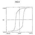
- FIG. 5 is a diagram showing in-plane magnetic characteristics of two CoPt layers separated by an Ru layer having a thickness of 1.4 nm.
- the ordinate indicates the residual magnetization (emu)
- the abscissa indicates the coercivity (Oe).
- the magnetization directions of the two CoPt layers are parallel.
- FIG. 6 is a diagram showing in-plane magnetic characteristics of two CoCrPt layers separated by an Ru layer having a thickness of 0.8 nm.
- the ordinate indicates the residual magnetization (emu/cc), and the abscissa indicates the coercivity (Oe).
- the loop shows shifts near the magnetic field which indicates the antiparallel coupling.
- the magnetic recording medium it is possible to increase the effective grain volume without sacrificing the resolution, by utilizing the exchange coupling between the magnetic layer and the ferromagnetic layer via the nonmagnetic coupling layer.
- the apparent thickness of the magnetic layer can be increased so that it is possible to realize a magnetic recording medium having a good thermal stability.
- the effective thickness of the magnetic layer does not change, because the reproduced output from the lower magnetic layer is cancelled. For this reason, the apparent thickness of the magnetic layer increases, but the effective thickness of the magnetic layer remains unchanged and can be kept small, thereby making it possible to obtain a high resolution which cannot be obtained by a magnetic recording medium having a thick magnetic layer. As a result, it is possible to obtain a magnetic recording medium having reduced medium noise and improved thermal stability.
- FIG. 9 is a cross sectional view showing an important part of a fifth embodiment of the magnetic recording medium according to the present invention.
- those parts which are the same as those corresponding parts in FIG. 8 are designated by the same reference numerals, and a description thereof will be omitted.
- an intermediate layer 32 shown in FIG. 9 is provide in place of the intermediate layer 31 shown in FIG. 8.
- the Co alloy intermediate layer 32 is made of CoCr 20 Pt 10 B 6 Cu 4 having the same composition as the magnetic layer 9 and has a thickness of 3.nm.
- the magnetic storage apparatus generally includes a housing 13.
- a motor 14, a hub 15, a plurality of magnetic recording media 16, a plurality of recording and reproducing heads 17, a plurality of suspensions 18, a plurality of arms 19, and an actuator unit 20 are provided within the housing 13.
- the magnetic recording media 16 are mounted on the hub 15 which is rotated by the motor 14.
- the recording and reproducing head 17 is made up of a reproducing head such as a MR or GMR head, and a recording head such as an inductive head.
- Each recording and reproducing head 17 is mounted on the tip end of a corresponding arm 19 via the suspension 18.
- the arms 19 are moved by the actuator unit 20.
- the basic construction of this magnetic storage apparatus is known, and a detailed description thereof will be omitted in this specification.
- a surface of the substrate may be subjected to a texturing process or an oxidation process, or it may be provided with an orientation adjusting layer.
Applications Claiming Priority (1)
| Application Number | Priority Date | Filing Date | Title |
|---|---|---|---|
| EP00979006A EP1359570A4 (fr) | 2000-11-29 | 2000-11-29 | Support magnetique d'enregistrement et dispositif magnetique de stockage |
Related Parent Applications (1)
| Application Number | Title | Priority Date | Filing Date |
|---|---|---|---|
| EP00979006A Division EP1359570A4 (fr) | 2000-11-29 | 2000-11-29 | Support magnetique d'enregistrement et dispositif magnetique de stockage |
Publications (1)
| Publication Number | Publication Date |
|---|---|
| EP1598813A1 true EP1598813A1 (fr) | 2005-11-23 |
Family
ID=34979287
Family Applications (1)
| Application Number | Title | Priority Date | Filing Date |
|---|---|---|---|
| EP05017215A Withdrawn EP1598813A1 (fr) | 2000-11-29 | 2000-11-29 | Moyen d'enregistrement magnétique et dispositif magnétique de stockage |
Country Status (1)
| Country | Link |
|---|---|
| EP (1) | EP1598813A1 (fr) |
Citations (1)
| Publication number | Priority date | Publication date | Assignee | Title |
|---|---|---|---|---|
| EP1059629A2 (fr) * | 1999-06-08 | 2000-12-13 | Fujitsu Limited | Milieu d'enregistrement magnétique, appareil de stockage magnétique, méthode d'enregistrement et méthode de production de milieu magnétique d'enregistrement |
-
2000
- 2000-11-29 EP EP05017215A patent/EP1598813A1/fr not_active Withdrawn
Patent Citations (1)
| Publication number | Priority date | Publication date | Assignee | Title |
|---|---|---|---|---|
| EP1059629A2 (fr) * | 1999-06-08 | 2000-12-13 | Fujitsu Limited | Milieu d'enregistrement magnétique, appareil de stockage magnétique, méthode d'enregistrement et méthode de production de milieu magnétique d'enregistrement |
Similar Documents
| Publication | Publication Date | Title |
|---|---|---|
| US6602612B2 (en) | Magnetic recording medium and magnetic storage apparatus | |
| US6689495B1 (en) | Magnetic recording medium and magnetic storage apparatus | |
| EP1302933B1 (fr) | Moyen d' enregistrement magnétique | |
| US7327528B2 (en) | Magnetic recording medium and magnetic storage apparatus | |
| US6645646B1 (en) | Magnetic recording medium and magnetic storage apparatus | |
| US6821652B1 (en) | Magnetic recording medium and magnetic storage apparatus | |
| US6623875B2 (en) | Magnetic recording medium and magnetic storage apparatus | |
| KR20020084220A (ko) | 자기 기록 매체 | |
| JP3848072B2 (ja) | 磁気記録媒体及びこれを用いた磁気記憶装置 | |
| US6753101B1 (en) | Magnetic recording medium, magnetic storage apparatus, recording method and method of producing magnetic recording medium | |
| US6551728B1 (en) | Magnetic recording medium and magnetic storage apparatus | |
| EP1359570A1 (fr) | Support magnetique d'enregistrement et dispositif magnetique de stockage | |
| JP3476739B2 (ja) | 磁気記録媒体 | |
| JP3476740B2 (ja) | 磁気記録媒体 | |
| JP3476741B2 (ja) | 磁気記録媒体及び磁気記憶装置 | |
| EP1598813A1 (fr) | Moyen d'enregistrement magnétique et dispositif magnétique de stockage | |
| JP2005228476A (ja) | 磁気記録媒体及び磁気記憶装置 | |
| JP2005038519A (ja) | 磁気記録媒体、その製造方法、及び磁気記憶装置 | |
| JP2003228826A (ja) | 磁気記録媒体の製造方法 |
Legal Events
| Date | Code | Title | Description |
|---|---|---|---|
| PUAI | Public reference made under article 153(3) epc to a published international application that has entered the european phase |
Free format text: ORIGINAL CODE: 0009012 |
|
| AC | Divisional application: reference to earlier application |
Ref document number: 1359570 Country of ref document: EP Kind code of ref document: P |
|
| AK | Designated contracting states |
Kind code of ref document: A1 Designated state(s): AT BE CH CY DE DK ES FI FR GB GR IE IT LI LU MC NL PT SE TR |
|
| AX | Request for extension of the european patent |
Extension state: AL LT LV MK RO SI |
|
| AKX | Designation fees paid | ||
| REG | Reference to a national code |
Ref country code: DE Ref legal event code: 8566 |
|
| STAA | Information on the status of an ep patent application or granted ep patent |
Free format text: STATUS: THE APPLICATION IS DEEMED TO BE WITHDRAWN |
|
| 18D | Application deemed to be withdrawn |
Effective date: 20060524 |