EP1598773A2 - Control of modules having programmable tags - Google Patents
Control of modules having programmable tags Download PDFInfo
- Publication number
- EP1598773A2 EP1598773A2 EP05104248A EP05104248A EP1598773A2 EP 1598773 A2 EP1598773 A2 EP 1598773A2 EP 05104248 A EP05104248 A EP 05104248A EP 05104248 A EP05104248 A EP 05104248A EP 1598773 A2 EP1598773 A2 EP 1598773A2
- Authority
- EP
- European Patent Office
- Prior art keywords
- tag
- electronic monitoring
- programming
- information
- module
- Prior art date
- Legal status (The legal status is an assumption and is not a legal conclusion. Google has not performed a legal analysis and makes no representation as to the accuracy of the status listed.)
- Granted
Links
- 238000012544 monitoring process Methods 0.000 claims abstract description 43
- 238000004891 communication Methods 0.000 claims description 76
- 238000000034 method Methods 0.000 claims description 19
- 230000004044 response Effects 0.000 claims description 11
- 238000012545 processing Methods 0.000 description 28
- 238000000926 separation method Methods 0.000 description 8
- 230000008569 process Effects 0.000 description 7
- 238000003780 insertion Methods 0.000 description 5
- 230000037431 insertion Effects 0.000 description 5
- 239000000463 material Substances 0.000 description 4
- 239000012611 container material Substances 0.000 description 2
- 230000006870 function Effects 0.000 description 2
- 238000012986 modification Methods 0.000 description 2
- 230000004048 modification Effects 0.000 description 2
- 108091008695 photoreceptors Proteins 0.000 description 2
- 238000004458 analytical method Methods 0.000 description 1
- 230000008901 benefit Effects 0.000 description 1
- 238000004364 calculation method Methods 0.000 description 1
- 238000013524 data verification Methods 0.000 description 1
- 238000013461 design Methods 0.000 description 1
- 238000005286 illumination Methods 0.000 description 1
- 238000009434 installation Methods 0.000 description 1
- 239000004973 liquid crystal related substance Substances 0.000 description 1
- 238000012423 maintenance Methods 0.000 description 1
- 238000007726 management method Methods 0.000 description 1
- 230000007246 mechanism Effects 0.000 description 1
- 230000003287 optical effect Effects 0.000 description 1
- 238000012856 packing Methods 0.000 description 1
- 230000011664 signaling Effects 0.000 description 1
- 230000005236 sound signal Effects 0.000 description 1
- 238000012546 transfer Methods 0.000 description 1
- 230000000007 visual effect Effects 0.000 description 1
Images


Classifications
-
- G—PHYSICS
- G06—COMPUTING; CALCULATING OR COUNTING
- G06K—GRAPHICAL DATA READING; PRESENTATION OF DATA; RECORD CARRIERS; HANDLING RECORD CARRIERS
- G06K17/00—Methods or arrangements for effecting co-operative working between equipments covered by two or more of main groups G06K1/00 - G06K15/00, e.g. automatic card files incorporating conveying and reading operations
-
- G—PHYSICS
- G06—COMPUTING; CALCULATING OR COUNTING
- G06K—GRAPHICAL DATA READING; PRESENTATION OF DATA; RECORD CARRIERS; HANDLING RECORD CARRIERS
- G06K19/00—Record carriers for use with machines and with at least a part designed to carry digital markings
- G06K19/06—Record carriers for use with machines and with at least a part designed to carry digital markings characterised by the kind of the digital marking, e.g. shape, nature, code
- G06K19/067—Record carriers with conductive marks, printed circuits or semiconductor circuit elements, e.g. credit or identity cards also with resonating or responding marks without active components
- G06K19/07—Record carriers with conductive marks, printed circuits or semiconductor circuit elements, e.g. credit or identity cards also with resonating or responding marks without active components with integrated circuit chips
- G06K19/073—Special arrangements for circuits, e.g. for protecting identification code in memory
-
- G—PHYSICS
- G06—COMPUTING; CALCULATING OR COUNTING
- G06K—GRAPHICAL DATA READING; PRESENTATION OF DATA; RECORD CARRIERS; HANDLING RECORD CARRIERS
- G06K19/00—Record carriers for use with machines and with at least a part designed to carry digital markings
- G06K19/06—Record carriers for use with machines and with at least a part designed to carry digital markings characterised by the kind of the digital marking, e.g. shape, nature, code
- G06K19/067—Record carriers with conductive marks, printed circuits or semiconductor circuit elements, e.g. credit or identity cards also with resonating or responding marks without active components
- G06K19/07—Record carriers with conductive marks, printed circuits or semiconductor circuit elements, e.g. credit or identity cards also with resonating or responding marks without active components with integrated circuit chips
- G06K19/077—Constructional details, e.g. mounting of circuits in the carrier
- G06K19/07749—Constructional details, e.g. mounting of circuits in the carrier the record carrier being capable of non-contact communication, e.g. constructional details of the antenna of a non-contact smart card
- G06K19/07758—Constructional details, e.g. mounting of circuits in the carrier the record carrier being capable of non-contact communication, e.g. constructional details of the antenna of a non-contact smart card arrangements for adhering the record carrier to further objects or living beings, functioning as an identification tag
- G06K19/0776—Constructional details, e.g. mounting of circuits in the carrier the record carrier being capable of non-contact communication, e.g. constructional details of the antenna of a non-contact smart card arrangements for adhering the record carrier to further objects or living beings, functioning as an identification tag the adhering arrangement being a layer of adhesive, so that the record carrier can function as a sticker
-
- G—PHYSICS
- G06—COMPUTING; CALCULATING OR COUNTING
- G06K—GRAPHICAL DATA READING; PRESENTATION OF DATA; RECORD CARRIERS; HANDLING RECORD CARRIERS
- G06K19/00—Record carriers for use with machines and with at least a part designed to carry digital markings
- G06K19/06—Record carriers for use with machines and with at least a part designed to carry digital markings characterised by the kind of the digital marking, e.g. shape, nature, code
- G06K19/067—Record carriers with conductive marks, printed circuits or semiconductor circuit elements, e.g. credit or identity cards also with resonating or responding marks without active components
- G06K19/07—Record carriers with conductive marks, printed circuits or semiconductor circuit elements, e.g. credit or identity cards also with resonating or responding marks without active components with integrated circuit chips
- G06K19/077—Constructional details, e.g. mounting of circuits in the carrier
- G06K19/07749—Constructional details, e.g. mounting of circuits in the carrier the record carrier being capable of non-contact communication, e.g. constructional details of the antenna of a non-contact smart card
- G06K19/07798—Constructional details, e.g. mounting of circuits in the carrier the record carrier being capable of non-contact communication, e.g. constructional details of the antenna of a non-contact smart card part of the antenna or the integrated circuit being adapted for rupturing or breaking, e.g. record carriers functioning as sealing devices for detecting not-authenticated opening of containers
Definitions
- the present invention relates to control of programmable devices or modules.
- the present invention is particularly useful in inventory and configuration control of modules that are physically identical but can be programmed with alternative configurations.
- a barcode containing a model number or a serial number or other identifying indicia can be printed on a device or a package.
- An optical scanner connected to a tracking system can scan the barcode, so that the tracking system can determine the identity and location of the marked item.
- Such barcode systems rely on "line of sight" access from the barcode reader to the barcode on the item being tracked.
- the tracking system can record various information pertaining to the location and status of the tracked item, the tracked item itself does not retain any information as to where it has been, or what processing steps have been performed on it.
- RFID devices include radio frequency transmitters that have been applied to products for tracking purposes. Such RFID devices contain information that they can transmit to a reader. The radio frequency transmitters do not require "line of sight” access from the reader.
- Magnetic tags and sensors have also been demonstrated to track and verify the identity of products. Magnetic tags require close proximity between the information bearing tag and the sensor.
- holders or transporters of products may wish to alter certain information pertaining to a particular product after the product has been manufactured and entered the distribution channel. For example, a person may wish to know when a product passed through a particular stage in the distribution channel. Such information is important to maintain the freshness of time-sensitive inventory. Also, for certain types of products, such information can be used to detect if the product may have been inappropriately detoured along the distribution channel, which detours could indicate tampering or other mishandling of the product.
- certain families of products may be physically identical but have different programmable characteristics. If the programmable characteristics are set to create separate "products" when the product first enters the distribution channel, inventory control is complicated because the holder of the inventory must manage the inventory of several different products.
- programming an electronic monitoring tag attached to a printing apparatus replaceable module includes electronically reading tag identification data from an electronic monitoring tag associated with the replaceable module, and electronically verifying that the tag identification data matches predetermined identification criteria. If the tag identification data matches the predetermined identification criteria, electronically programming the electronic monitoring tag with tag content.
- a programming device for programming electronic monitoring tags that are associated with printing apparatus replaceable modules, includes a tag writer adapted to program tag content into electronic monitoring tags, and a tag reader.
- the tag reader is adapted to read tag identification data from a first electronic monitoring tag associated with a printing apparatus replaceable module.
- the programming device also includes a data verifier that communicates with the tag reader.
- the data verifier is adapted to determine if the read tag identification data matches predetermined tag identification criteria, and to authorize the tag writer to program the tag content into the first electronic monitoring tag only if the data verifier determines that the tag identification data matches the tag identification criteria.
- the device additionally comprises:
- Figure 1 shows an exemplary application of a programmable module tag to a module.
- Figure 2 shows an exemplary application of a programmable module tag to a container for a module.
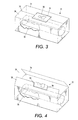
- Figure 3 shows another application of a programmable module tag to a container for a module.
- Figure 4 shows the programmable module tag applied as shown in Figure 3, after the container has been opened.
- Figure 5 shows an exemplary implementation of a programmable module tag.
- Figure 6 illustrates a use of a portable tag programmer to program a module tag.
- Figure 7 illustrates a use of a portable tag programmer to program a module tag.
- Figure 8 is a perspective view of one implementation of a portable module tag programmer.
- Figure 9 is a cross-sectional view of the portable module tag programmer of Figure 8, taken along line 9 - 9 of Figure 8.
- Figure 10 is a top view of the portable module tag programmer of Figure 8.
- Figure 11 is a rear end view of the portable module tag programmer of Figure 8.
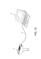
- Figure 12 is a perspective view of a system incorporating a module tag programmer.
- Figure 13 is a simplified flowchart of a tag programming process.
- Figure 14 is a conceptual illustration of a printing apparatus incorporating one implementation of a module tag reader.
- Figure 15 is a simplified elevational view of the installation of a portion of the printing apparatus of Figure 12.
- Programmable tags are attached to, or otherwise associated with, various types of products, such as replaceable modules for printing apparatus or other machinery.
- Such programmable tags include a tag memory in which information can be stored.
- a programmable electronic module tag 20 is associated with a module, such as a replacement part or consumable element for machinery or systems.
- a module such as a replacement part or consumable element for machinery or systems.
- a consumable module for a printing apparatus in particular a toner cartridge 30 containing consumable toner.
- the cartridge 30 is intended for insertion into a xerographic printing apparatus, in which toner is dispensed from the cartridge for use in the printing process.
- the electronic tag includes tag electronics 22 that include tag memory 24 for storing information, and a tag communication element 26 for communicating information to and from the electronic module tag.
- a processor (CPU) 28 provides computational and other capabilities.
- Interface electronics 29 connect the CPU 28, memory 24, and communication element 26. Many configurations are available for arranging and connecting elements of the electronic module tag.
- the communication element 26 is a wireless communication element for establishing a wireless communication link with another device.
- the wireless communication element is a radio frequency (RF) antenna for establishing a radio frequency communication link with another device.
- RF radio frequency
- the wireless communication element can be an active element, powered by a power source, such as a battery (not shown) embedded on the tag.
- the wireless communication element can be passive.
- a passive element is energized by the RF signal it receives from another device, such as an RF reader that queries the tag, or an RF writer that delivers information to the tag. Energy from the reader or writer is sufficient to briefly power the RF antenna and interface electronics to enable the RF antenna to receive and transmit information.
- Information is stored in the tag memory contained within the tag electronics. Particular information can be stored at particular locations in the tag memory. One path for receiving information to store in the tag memory is through the RF antenna. Information can also be read from the memory. When the communication element is activated, the RF antenna can transmit selected information from the tag memory.
- a wired communication element may connect the tag memory 24 through a plug or other connector to an external communication system for delivering information to, and drawing information from, the tag memory.
- the electronic module tag 20 can be attached directly to the toner cartridge module 30, as shown in Figure 1.
- the module 30 is enclosed within a container 32 for storage and transport, as shown in Figures 2 - 4.
- the tag 20 is embedded in the material forming the container (such as corrugated cardboard).
- the container may also enclose packing material (not shown) to protect the enclosed module.
- the container may enclose multiple modules, which may be identical to one another, or may form a set of related modules.
- the module such as the toner cartridge 30, is associated with an electronic module tag 20 on the container 32 by placing the module in the container having the programmable electronic tag 20.
- the module enclosed within the container may or may not have a separate electronic tag 20 affixed directly to the module ( Figure 1).
- the electronic tag 20 is attached with a label 33 to the container 32.
- One portion of the container (shown in Figure 3 as the top) has an opening separation 34 that is adapted to expand upon opening the container.
- the opening separation is formed in the top surface by forming the top surface as two sections 36, 38 of container material that meet at a seam forming the opening separation 34.
- the container with the opening separation expanded to open the container is shown in Figure 4.
- Other types of opening separations are also known.
- the container may be formed of a container body with an open side and a separate piece of material to form a lid, having an opening separation that extends around the perimeter of the lid, where the edge of the lid meets the container body.
- Other types of opening separations might include a pull tab that tears the container material, or that has a line of perforations to permit the pull tab to separate to sections of the container.
- the label bearing the electronic tag is securely attached to the container, preferably spanning the opening separation.
- Information can be stored in the tag memory of the module tag 20 after the module tag has been attached to a particular module, attached to the container enclosing a particular module, or in some other manner associated with a particular module. Thus, information can be added to the tag memory at different times and when the module is at different locations.
- a tag programmer 40 ( Figures 6 and 7) is adapted to program the module tag 20 after the module tag has been associated with a particular module.
- the tag programmer is adapted to cause information to be stored in the tag memory of a tag associated with a particular module.
- the tag programmer 40 may have a fixed location, as shown in Figure 6.
- the tag programmer is secured to a programmer fixture 42.
- the stationary tag programmer and its fixture are configured so that a module or a container enclosing a module, bearing a programmable electronic module tag, can be brought into proximity with the tag programmer.
- the tag programmer may be included in a portable tag processing device, as shown in Figure 7.
- the tag programmer 40 includes a tag reader that can electronically read information from the electronic module tag, and a tag writer that can program information into the electronic module tag. In either the fixed or portable tag programmer, most, if not all, components may be shared between the tag reader and the tag writer.
- the tag programmer 40 includes tag programmer electronics 44 (shown stylistically), and a tag programmer communication element 46.
- the tag programmer communication element 46 communicates with the tag communication element 26 of the electronic tag to form a communication link between the tag programmer and the electronic module tag.
- the tag programmer communication element 46 is a wireless communication element, such as an RF antenna.
- the RF antenna of the tag programmer emits sufficient energy to energize the RF antenna of the wireless communication element 26 of the tag when the tag programmer communication element 46 and the tag communication element 26 are within a predetermined operating range of one another.
- the tag programmer establishes a communication link between the tag programmer and the electronic tag.
- the tag programmer and the electronic tag can exchange information across that communication link.
- a radio frequency wireless communication link is shown, other types of communication links can also be used.
- wires connected with plugs or sockets can provide wired communication links between the tag reader and the electronic tag.
- An external communication link provided by, for example, a wire or cable 48, allows data to pass to and/or from the tag programmer to another system, such as a computer or other information management system.
- a tag processing device 50 incorporating the tag programmer 40 includes user interface components.
- Such user interface components include a user input element so a user can provide information to the tag programmer, and a user notification element so the tag programmer can convey information to the user.
- the user input element includes a keypad 52 connected to the programmer electronics 44.
- the keypad provides a means for a user to supply input information, such as programming instructions, to the processor electronics 44 of the tag programmer.
- a microphone and voice recognition capabilities can be used as a user input element.
- Such a microphone and voice recognition capability can reside on a computer, and be connected through a wired communications port 54 to provide user input signals from the computer to the tag programmer.
- a connecting device such as a cable, is selectively attached to the wired communications port.
- the progammer electronics of the tag processing device may include device memory for storing information during operation. Internal storage allows the tag processing device to download (or upload) data and information at intervals. This capability to store information allows tag processing device to be operated for a time without being in continuous communication with an external system through the communications port.
- the user can supply input information through a computer, using the computer's keyboard or mouse.
- An exemplary arrangement is shown in Figure 12 including a portable computer 95 connected to the tag processing device 50 through a cable 96.
- One end of the cable is attached to the tag processing device through the wired communications port 54.
- the other end of the cable attaches to the portable computer through one of the several ports typically available on a computer, such as a parallel (printer) port, a serial port, or a USB (universal serial bus) port.
- the information input to the computer can be translated as user input signals from the computer to the tag programmer through the communications port 54.
- Communication to the portable tag programmer can also be conducted wirelessly, such as with infrared or radio frequency signals.
- An external antenna 56 provides an exemplary connection point for receiving user input information from another element or system over a wireless communication link.
- An antenna switch 58 provides the ability to connect or disconnect the external antenna, or to transfer communication capability between the external antenna and the communications port 54. Persons familiar with the art will identify other mechanisms for supplying information from a user to the tag processing device 50 for use by the tag programmer.
- the tag programmer electronics 44 include a data processor 59.
- the data processor processes data received at the programmer communication element 46, and also information received from the user input element 52.
- the data processor manipulates the data according to predetermined criteria.
- the data processor can be adapted to interpret instructions received from the user input element, to verify information that is received from a module tag over the programmer communication element 46, or to perform calculations upon data received from the module tag.
- the tag programmer processor is also adapted to cause certain information to be communicated to the module tag, such as by transmitting the information over the programmer communication element 46.
- the user interface of the tag processing device also includes user notification elements for communicating information to the user.
- the user notification elements may include a graphical user interface 60, signal lights 62, and/or an audio output 64.
- the graphical user interface is adapted to display graphical or text messages, and may be a liquid crystal display (LCD) screen.
- the programmer electronics controls the messages displayed on the graphical user interface.
- the graphical user interface can also display information confirming the data entered by the user on the keypad 52.
- Signal lights 62 can provide simple visual signals to the user. For example, two signal lights may be included, with one red to indicate a negative condition or result, and the other green to indicate a positive condition or result. A third signal light may indicate a separate function, such as a power-on condition, or may provide a tri-level condition indicator. Other embodiments may have other numbers of signal lights.
- the signal lights may be light emitting diodes (LED's) or other light emitting devices.
- An audio output such as a speaker 64, is adapted to provide additional user notification by emitting one or more audible signals.
- audible signals may signal different conditions. For example, a 'buzzer' tone may indicate a negative condition or result, while a 'beep' tone may indicate a positive condition or result.
- Audible signals can be used to draw attention to certain conditions. In certain instances, simple signaling devices such as the signal lights and the audio signal output may be able to provide sufficient information to the user, eliminating the need for the graphical user interface.
- the portable tag processing device 50 is powered by a self-contained battery 66.
- a switch 68 allows the user to selectively turn the tag processing device on and off.
- the portable tag processing device is tethered to a power source with a power cord (not shown).
- tag programmer and other elements of the tag processing device may be positioned at the point of use at which the tag programmer to be proximate the module or module-enclosing container having the programmable module tag.
- tag programmer antenna 46 and some immediate support electronics may be at the point of use.
- Other portions of the processor electronics and the user interface elements can be positioned remote from the point of use, connected to the tag programmer antenna by additional communication elements (not shown).
- FIGS 6 and 7 conceptually illustrate programming the electronic module tag that is associated with a module.
- the drawing shows an arrangement in which the programmable electronic module tag 20 is secured to a container 32 enclosing the module, persons skilled in the art will recognize that the process can also be applied to an electronic module tag attached to the module itself. The process can be applied to a module having an attached module tag whether the module is enclosed within a container or outside of a container.
- the electronic module tag 20 is brought into proximity with the tag programmer by bringing the module with which the electronic module tag 20 is associated into proximity with the tag programmer.
- the container 32 enclosing the module 30 ( Figure 3) and bearing the electronic module tag 20 is brought close enough to the stationary tag programmer that the communication link is established between the electronic module tag and the tag programmer.
- the communication link is established through the tag programmer communication element 46 and the module tag communication element 26.
- the tag programmer can be moved into proximity with the tag 20 to be programmed.
- the tag reader of the tag programmer 40 can read information from the tag memory 24 of the electronic module tag 20 ( Figure 5).
- the tag reader may read tag identification information from the tag memory 110.
- tag identification information may include authentication information that the tag reader can use to verify the genuineness of the electronic module tag.
- the tag reader may read other identification information that identifies a model number or a configuration status for the module with which the electronic module tag is associated.
- the user may press a special purpose button on the keypad 52 of the tag processing device to initiate the tag reading process.
- the tag processing device may be configured to periodically emit tag reading instructions whenever the tag processing device is turned on.
- the tag processing device emits an identification request.
- the tag electronics 22 are configured to respond to the identification request by transmitting a tag response that includes the identification information.
- the nature of the identification request and the tag response depends on details of design, and may include additional security features.
- the tag response may include data from particular locations in the tag memory 24. Or, for enhanced security, the tag CPU 28 may calculate a tag response based on particular data from the tag memory, and perhaps information contained in the identification request. Persons familiar with data communication and data security will be familiar with various techniques to provide data and data security over a communication link such as the communication link between the electronic module tag and the tag reader segment of the tag programmer.
- the tag programmer communication element 46 receives the tag response, and directs the tag response signal to the appropriate reader portions of the tag programmer electronics 44.
- the tag programmer communication element 46 receives the response from the module tag.
- This tag response includes the tag identification information from the electronic module tag.
- the data processor 44 verifies the tag identity by comparing the identification information in the tag response with predetermined identification criteria to determine if the identification information matches that predetermined identification criteria. Persons familiar with data verification will be familiar with various types of identification criteria, and various techniques for determining if the identification information matches the predetermined identification criteria.
- the data processor may cause the tag programmer to program the electronic module tag 114.
- the data processor causes the programmer communication element 46 to transmit tag content information toward the electronic module tag.
- the tag communication element 26 receives the transmitted tag content information.
- the tag electronics 22 are configured to then store the appropriate tag content in the tag memory 24.
- the tag content may include module configuration setup information, such as described in U.S. Patent Application Serial No. XX/XXX,XXX (Attorney Docket No. A2132Q-US-NP), filed concurrently herewith by Heiko Rommelmann et al., and entitled "Control of Programmable Modules," the contents of which are hereby incorporated by reference. Such storage can take place in a variety of ways familiar to persons skilled in the art.
- the user may be called upon to supply the tag processing device with tag content programming instructions through the user input element of the user interface 116.
- the user may press a predetermined series of keys on the keypad 52 to cause the tag programmer of the tag processing device to generate a particular set of tag content.
- the data processor of the tag programmer can be adapted to confirm that the user instruction for particular tag content is authorized for, or consistent with a particular module.
- the module can be identified by the identification information on the electronic tag associated with the module.
- the data processor can compare 118 the identification information received from the electronic tag with predetermined identification criteria for modules authorized to receive the configuration instructions provided by the user. If the tag content is authorized for the identified module, the tag programmer proceeds to program the electronic module tag. If, however, the tag content is not authorized for the identified module, the tag processing device provides a signal to the user 120. Such a signal can be an audible signal on the audio output 64, a visible signal on one or more of the signal lights 62, and/or a message on the graphical user interface 60.
- the tag processing device may also be adapted to verify 124 that the user providing tag content programming instructions is authorized to do so, and to submit the particular tag content provided.
- the tag processing device may prompt the user to input user identifying information.
- the user may provide 122 such user identifying information through the keypad 52, or the tag processing device may include an identification reader device for reading a key card or other device that is associated with the user.
- the tag processing device may be part of the programming system provided with functionality like that described in U.S. Patent Application Serial No. 10/634,934 by Alberto Rodriguez et al., Control of Programming Electronic Devices, filed August 5, 2003, the contents of which are hereby incorporated by reference. Such functionality may include security features to control access to the programming capabilities of the programming system.
- a variety of combinations of the above features may be included for maximum flexibility of use, and for security. For example, certain users can be authorized to provide only certain types of tag content, or to provide tag content for only certain types of modules (as identified by their tag identification information). A particular user may be authorized to provide only a limited number of programming instructions (i.e., to limit the number of module tags a particular user is entitled to program).
- a signal may be provided to the user 126 to indicate successful programming of tag content into the tag.
- This signal may include illumination of a signal light 62, an audible signal, or a message on the GUI 60.
- Information can be added to the tag memory at different times.
- certain information such as the physical configuration of the module enclosed within the container, may be stored in the tag memory at one time, such as upon placing the module in the container.
- Additional information such as the marketing part number, may be added at a later time.
- additional information such as tracking information indicating a particular distributor warehouse, the particular service technician who installs the module, or other information can be added at later times.
- tracking information can be stored in the tag memory attached to the container, so that the container itself retains a history of where it has been, and what steps have performed upon it. In this way, a subsequent tag reader can access this information and identify the history of the container enclosing the module, without requiring that the tag reader access a central tracking system.
- FIG 14 shows a representative printing apparatus 70 that might use the module 30 enclosed within the container 32.
- the representative printing apparatus includes a printing subsystem 72, which, in the illustrated example, is a xerographic printing subsystem that includes a photoreceptor 74, and a developer 73.
- a toner cartridge such as the toner cartridge module 30 enclosed within the container, is inserted into the printing subsystem.
- the developer draws toner from the toner cartridge into the developer.
- the printing apparatus additionally includes a fuser subassembly 78, an electronic subsystem 80 for processing control signals, and a distribution component 82 for controlling the distribution of electronic signals from the electronic subsystem to the printing subassembly and the fusing subassembly.
- the distribution components may also deliver information to a graphical display 84 for conveying information to the machine user.
- the printing apparatus may include a copying function, in which case a document handler 86 passes documents past a scanner 88.
- the printing apparatus includes a printer tag reader 90 that includes a wireless reader communication element 92 for receiving information transmitted by the communication element 26 of the module tag 20.
- the tag reader on the printing apparatus includes reader electronics 94 and an RF antenna forming the wireless reader communication element 92.
- the RF antenna emits radio frequency signals of sufficient strength to energize the RF antenna forming the tag communication element 26 on the tag when the tag is brought into proximity with the printer tag reader.
- the tag communication element Upon being energized, the tag communication element transmits information stored in the tag memory portion of the tag electronics 24.
- the wireless reader communication element 92 receives that information, and either processes the information within the printer tag reader electronics 94, or transmits the information it to the printer electronic subsystem 80 of the printing apparatus.
- the printer tag reader electronics 94 or the printer electronic subsystem 80 analyze the tag information received from the module tag 20.
- the tag information read and analyzed by the printer tag reader electronics 94 or the printer electronic subsystem 80 includes the configuration information stored in the tag memory by the tag programmer 40.
- the analysis may be to verify that the tag information indicates that the module enclosed in the container is appropriate for the particular printing apparatus by comparing the tag configuration information with predetermined configuration parameters.
- the printer electronic subsystem may verify that the tag information indicates that the module is intended for a printing apparatus with the appropriate type of maintenance agreement that covers the particular printing apparatus 70.
- the electronic subsystem may use the tag information from the tag on the container to determine the type of material in the container.
- the printer electronic subsystem 80 may be configured to perform various actions depending on the information received.
- the information received from the tag may indicate to the electronic subsystem how the printer should be configured to take advantage of the module contained in the container.
- the electronic subsystem can also be configured to issue a notice on a printer user interface, such as a graphical display 84, if the tag information read from the module tag indicates that an incorrect module is being presented to the printing apparatus.
- the electronic subsystem may even be programmed to block insertion of the module into the printing apparatus if the information read from the tag memory does not agree with the expected information.
- a module tag 20 is attached directly to the module 30 so that the contents of the module tag can be read by a printer tag reader 76 in the printing apparatus during use of the printing apparatus.
- the printing apparatus may be adapted so that if the printing apparatus, through the printer tag reader, determines that the module tag is programmed with one set of configuration information, the printing apparatus operates in a first manner, or if the module tag is programmed with a second set of configuration information, the printing apparatus operates in a second, different manner.
- the module is a toner cartridge for a developer 73, such differences may include adjustments such as altering the concentration of toner deposited by the developer onto the photoreceptor 74. Or the differences may include adjustments to the methodology the printing apparatus uses to estimate toner usage, or other factors affecting printer performance.
- the printer tag reader 90 is installed adjacent where the module 30 is to be installed.
- the printer may include an insertion tray 75 to receive the toner module.
- the printer tag reader 76 may be contained in the insertion tray.
- a printer tag reader 90a is mounted adjacent the insertion tray, or along the path that the module 30 takes as the module is inserted into the printer.
- the printer tag reader 90a includes a wireless communication element 92a and reader electronics 94a.
Landscapes
- Engineering & Computer Science (AREA)
- Computer Hardware Design (AREA)
- Microelectronics & Electronic Packaging (AREA)
- Physics & Mathematics (AREA)
- General Physics & Mathematics (AREA)
- Theoretical Computer Science (AREA)
- Computer Security & Cryptography (AREA)
- General Engineering & Computer Science (AREA)
- Accessory Devices And Overall Control Thereof (AREA)
- Control Or Security For Electrophotography (AREA)
Abstract
Description
In one embodiment of the programming device of
In a further embodiment:
- the data verifier is additionally adapted to determine if the user instructions match predetermined user criteria; and
- the data verifier is additionally adapted to authorize the tag writer to program the tag content into the first electronic monitoring tag only if the data verifier additionally determines that the user instruction match the predetermined user criteria.
- the data verifier is adapted to determine whether the tag identification data matches first identification criteria or second identification criteria;
- the tag writer is adapted to authorize the tag writer to program first tag content into the first electronic monitoring tag only if the data verifier determines that the tag identification data matches the first identification criteria; and
- the tag writer is adapted to authorize the tag writer to program second tag content into the first electronic monitoring tag only if the data verifier determines that the tag identification data matches the second identification criteria.
- the tag writer comprises a writer wireless communication element for transmitting programming information; and
- the data receiver comprises a reader wireless communication element for receiving the tag identification data.
In one embodiment of the programming device of claim 10, the wireless writer communication element and the wireless reader communication element are a common wireless communication element.
In a further embodiment:
- the tag writer is a portable tag writer; and
- the tag reader is a portable tag reader.
Claims (10)
- A method of programming an electronic monitoring tag attached to a printing apparatus replaceable module, the method comprising:If the tag identification data matches the predetermined identification criteria, electronically programming the electronic monitoring tag with tag content.electronically reading tag identification data from an electronic monitoring tag associated with the replaceable module;electronically verifying that the tag identification data matches predetermined identification criteria; and
- The method of claim 1, wherein programming the electronic monitoring tag with tag content comprises selectively programming the electronic monitoring tag with first configuration information or with second configuration information.
- The method of claim 2 additionally comprising:providing user input information comprising first configuration setup information or second configuration setup information; andprogramming the electronic monitoring tag comprises programming the electronic monitoring tag with first configuration information if the user input information comprises first configuration setup information, and programming the electronic monitoring tag with second configuration information if the user input information comprises the second configuration setup information.
- The method of claim 2, additionally comprising:transmitting first operating information to the printer if the electronic monitoring tag has been programmed with the first configuration information; andtransmitting second operating information to the printer if the electronic monitoring tag has been programmed with the second configuration information.
- The method of claim 1, wherein:verifying that the tag identification data matches the predetermined identification criteria comprises determining whether the tag identification data matches a first predetermined identification criteria or a second predetermined identification criteria; andprogramming the electronic monitoring tag with tag content comprises programming the electronic monitoring tag with first configuration information if the tag identification data matches the first predetermined identification criteria, or programming the electronic monitoring tag with second configuration information if the tag identification data matches the second predetermined identification criteria.
- The method of claim 5, additionally comprising:reading tag authentication data from the electronic monitoring tag;verifying that the tag authentication data matches predetermined authentication criteria; andprogramming the electronic monitoring tag with tag content only if the tag authentication data matches the predetermined authentication criteria.
- The method of claim 6, wherein reading the tag authentication data comprises:electronically transmitting an authentication request signal to the electronic monitoring tag;causing the electronic monitoring tag to calculate an authentication response; andelectronically receiving the authentication response from the electronic monitoring tag.
- The method of claim 1, wherein programming the electronic monitoring tag with first tag content comprises programming the tag with tag information relating to the subsequent use of the printing apparatus replaceable module.
- A programming device for programming electronic monitoring tags that are associated with printing apparatus replaceable modules, the programming device comprising:a tag reader;a tag writer adapted to program tag content into electronic monitoring tags;
wherein the tag reader is adapted to read tag identification data from a first electronic monitoring tag associated with a printing apparatus replaceable module; and
a data verifier in communication with the tag reader;
wherein the data verifier is adapted to determine if tag identification data matches predetermined identification criteria; and
wherein the data verifier is adapted to authorize the tag writer to program the tag content into the first electronic monitoring tag only if the data verifier determines that the tag identification data matches the identification criteria. - A programming device for programming electronic monitoring tags that are associated with printing apparatus replaceable modules, the programming device comprising:wherein the tag writer comprises a wireless communication element and is adapted to program either first tag content or second tag content into electronic monitoring tags using the wireless writer communication element; a tag reader;a tag writer;
wherein the tag reader comprises a wireless communication element and is adapted to read tag identification data from a first electronic monitoring tag associated with a printing apparatus replaceable module using the wireless reader communication element; and
a user input element for receiving user instructions; a data verifier in communication with the tag reader, the user input element, and the tag writer;
wherein the data verifier is adapted to determine whether the tag identification data received by the tag reader matches predetermined tag identification criteria;
wherein the data verifier is adapted to authorize the tag writer to program the first tag content into the first electronic monitoring tag only if the data verifier determines that the received tag identification data matches the tag identification criterion and the user input element receives a first user instruction; and
wherein the data verifier is adapted to authorize the tag writer to program the second tag content into the first electronic monitoring tag only if the data verifier determines that the received tag identification data matches the tag identification criterion and the user input element receives a second user instruction.
Applications Claiming Priority (2)
| Application Number | Priority Date | Filing Date | Title |
|---|---|---|---|
| US849976 | 1986-04-10 | ||
| US10/849,976 US7053776B2 (en) | 2004-05-20 | 2004-05-20 | Control of programmable modules |
Publications (3)
| Publication Number | Publication Date |
|---|---|
| EP1598773A2 true EP1598773A2 (en) | 2005-11-23 |
| EP1598773A3 EP1598773A3 (en) | 2008-05-28 |
| EP1598773B1 EP1598773B1 (en) | 2011-12-28 |
Family
ID=34939895
Family Applications (1)
| Application Number | Title | Priority Date | Filing Date |
|---|---|---|---|
| EP05104248A Active EP1598773B1 (en) | 2004-05-20 | 2005-05-19 | Control of modules having programmable tags |
Country Status (3)
| Country | Link |
|---|---|
| US (1) | US7053776B2 (en) |
| EP (1) | EP1598773B1 (en) |
| JP (1) | JP4880247B2 (en) |
Families Citing this family (3)
| Publication number | Priority date | Publication date | Assignee | Title |
|---|---|---|---|---|
| US20050258228A1 (en) * | 2004-05-20 | 2005-11-24 | Xerox Corporation | Control of programmable modules |
| US20110058201A1 (en) * | 2009-09-08 | 2011-03-10 | Xerox Corporation | Method and apparatus for identifying parts in an image production device |
| US9317009B2 (en) * | 2014-02-19 | 2016-04-19 | Xerox Corporation | Systems and methods for mounting an externally readable monitoring module on a rotating customer replaceable component in an operating device |
Citations (1)
| Publication number | Priority date | Publication date | Assignee | Title |
|---|---|---|---|---|
| WO1998052162A2 (en) | 1997-05-15 | 1998-11-19 | Mondex International Limited | Secure multiple application card system and process |
Family Cites Families (17)
| Publication number | Priority date | Publication date | Assignee | Title |
|---|---|---|---|---|
| US6078251A (en) * | 1996-03-27 | 2000-06-20 | Intermec Ip Corporation | Integrated multi-meter and wireless communication link |
| US6176425B1 (en) | 1998-09-10 | 2001-01-23 | Xerox Corporation | Information management system supporting multiple electronic tags |
| US6008727A (en) | 1998-09-10 | 1999-12-28 | Xerox Corporation | Selectively enabled electronic tags |
| US6326946B1 (en) | 1998-09-17 | 2001-12-04 | Xerox Corporation | Operator icons for information collages |
| JP3412532B2 (en) | 1998-09-25 | 2003-06-03 | 三菱マテリアル株式会社 | Article identification device |
| JP2001242752A (en) * | 2000-02-25 | 2001-09-07 | Minolta Co Ltd | The recycling method and image forming device |
| US6262662B1 (en) | 2000-02-25 | 2001-07-17 | Xerox Corporation | Systems and methods that detect proximity information using electric field sensing devices and a page identification using embedded identification tags |
| US6351621B1 (en) | 2000-06-26 | 2002-02-26 | Xerox Corporation | Wireless interaction with memory associated with a replaceable module for office equipment |
| US6584290B2 (en) | 2000-12-19 | 2003-06-24 | Xerox Corporation | System for providing information for a customer replaceable unit |
| US6969134B2 (en) * | 2001-10-01 | 2005-11-29 | Zih Corp. | Printer or other media processor with on-demand selective media converter |
| JP2003270920A (en) * | 2002-03-19 | 2003-09-25 | Fuji Xerox Co Ltd | Toner cartridge and image forming apparatus |
| DE10232783A1 (en) * | 2002-07-18 | 2004-02-19 | Quotas Gmbh | Logistic chain quality control method in which a non-detectable transponder is added to a delivery item so that it can collect times and details of its delivery path from read-write antenna devices along its delivery path |
| JP4047691B2 (en) * | 2002-10-10 | 2008-02-13 | 日本電信電話株式会社 | Article ownership confirmation system, article ownership confirmation method, article ownership confirmation program, and recording medium for the program |
| US20050258228A1 (en) | 2004-05-20 | 2005-11-24 | Xerox Corporation | Control of programmable modules |
| US7196627B2 (en) | 2004-05-20 | 2007-03-27 | Xerox Corporation | Control of packaged modules |
| US7158032B2 (en) | 2004-05-20 | 2007-01-02 | Xerox Corporation | Diagnosis of programmable modules |
| US7106198B2 (en) | 2004-05-20 | 2006-09-12 | Xerox Corporation | Control of programmable modules |
-
2004
- 2004-05-20 US US10/849,976 patent/US7053776B2/en active Active
-
2005
- 2005-05-16 JP JP2005142330A patent/JP4880247B2/en active Active
- 2005-05-19 EP EP05104248A patent/EP1598773B1/en active Active
Patent Citations (1)
| Publication number | Priority date | Publication date | Assignee | Title |
|---|---|---|---|---|
| WO1998052162A2 (en) | 1997-05-15 | 1998-11-19 | Mondex International Limited | Secure multiple application card system and process |
Also Published As
| Publication number | Publication date |
|---|---|
| JP4880247B2 (en) | 2012-02-22 |
| JP2005332394A (en) | 2005-12-02 |
| US7053776B2 (en) | 2006-05-30 |
| US20050258932A1 (en) | 2005-11-24 |
| EP1598773B1 (en) | 2011-12-28 |
| EP1598773A3 (en) | 2008-05-28 |
Similar Documents
| Publication | Publication Date | Title |
|---|---|---|
| EP1598768B1 (en) | Control of programmable modules | |
| US7158032B2 (en) | Diagnosis of programmable modules | |
| EP1598774B1 (en) | Control of packaged modules | |
| US11758940B2 (en) | Methods and devices for cartridge authentication | |
| US7586413B2 (en) | Human feedback using parasitic power harvesting of RFID tags | |
| TW201015448A (en) | Transient state information display in an RFID tag having a charge-induced pigment release medium | |
| CN103209623B (en) | Wrapped by material for monitoring and controlling or encapsulation prepares the system of operator scheme of machine of beverage, particularly coffee | |
| WO2015009900A1 (en) | Systems and methods for authenticating goods | |
| KR20080023635A (en) | Contactless data communication system and contactless ic tag | |
| WO2015145179A1 (en) | Point of sale system and scanner | |
| US7643948B2 (en) | Secure resource tracker | |
| EP1598773B1 (en) | Control of modules having programmable tags | |
| KR20140079555A (en) | Check system of authenticity product | |
| EP1598772A2 (en) | Control of modules having programmable tags | |
| JP6848365B2 (en) | Logistics management system | |
| JP2006219262A (en) | Article prober and article probing system | |
| JPH10269331A (en) | Non-contact ic card and non-contact ic card reader and writer | |
| JP2006072883A (en) | Card system |
Legal Events
| Date | Code | Title | Description |
|---|---|---|---|
| PUAI | Public reference made under article 153(3) epc to a published international application that has entered the european phase |
Free format text: ORIGINAL CODE: 0009012 |
|
| AK | Designated contracting states |
Kind code of ref document: A2 Designated state(s): AT BE BG CH CY CZ DE DK EE ES FI FR GB GR HU IE IS IT LI LT LU MC NL PL PT RO SE SI SK TR |
|
| AX | Request for extension of the european patent |
Extension state: AL BA HR LV MK YU |
|
| PUAL | Search report despatched |
Free format text: ORIGINAL CODE: 0009013 |
|
| AK | Designated contracting states |
Kind code of ref document: A3 Designated state(s): AT BE BG CH CY CZ DE DK EE ES FI FR GB GR HU IE IS IT LI LT LU MC NL PL PT RO SE SI SK TR |
|
| AX | Request for extension of the european patent |
Extension state: AL BA HR LV MK YU |
|
| 17P | Request for examination filed |
Effective date: 20081128 |
|
| 17Q | First examination report despatched |
Effective date: 20081223 |
|
| AKX | Designation fees paid |
Designated state(s): DE FR GB |
|
| GRAP | Despatch of communication of intention to grant a patent |
Free format text: ORIGINAL CODE: EPIDOSNIGR1 |
|
| GRAS | Grant fee paid |
Free format text: ORIGINAL CODE: EPIDOSNIGR3 |
|
| GRAA | (expected) grant |
Free format text: ORIGINAL CODE: 0009210 |
|
| AK | Designated contracting states |
Kind code of ref document: B1 Designated state(s): DE FR GB |
|
| REG | Reference to a national code |
Ref country code: GB Ref legal event code: FG4D |
|
| REG | Reference to a national code |
Ref country code: DE Ref legal event code: R082 Ref document number: 602005031845 Country of ref document: DE Representative=s name: GRUENECKER, KINKELDEY, STOCKMAIR & SCHWANHAEUS, DE Ref country code: DE Ref legal event code: R082 Ref document number: 602005031845 Country of ref document: DE Representative=s name: GRUENECKER PATENT- UND RECHTSANWAELTE PARTG MB, DE |
|
| REG | Reference to a national code |
Ref country code: DE Ref legal event code: R096 Ref document number: 602005031845 Country of ref document: DE Effective date: 20120308 |
|
| PLBE | No opposition filed within time limit |
Free format text: ORIGINAL CODE: 0009261 |
|
| STAA | Information on the status of an ep patent application or granted ep patent |
Free format text: STATUS: NO OPPOSITION FILED WITHIN TIME LIMIT |
|
| 26N | No opposition filed |
Effective date: 20121001 |
|
| REG | Reference to a national code |
Ref country code: DE Ref legal event code: R097 Ref document number: 602005031845 Country of ref document: DE Effective date: 20121001 |
|
| REG | Reference to a national code |
Ref country code: FR Ref legal event code: PLFP Year of fee payment: 12 |
|
| REG | Reference to a national code |
Ref country code: FR Ref legal event code: PLFP Year of fee payment: 13 |
|
| REG | Reference to a national code |
Ref country code: FR Ref legal event code: PLFP Year of fee payment: 14 |
|
| PGFP | Annual fee paid to national office [announced via postgrant information from national office to epo] |
Ref country code: GB Payment date: 20240419 Year of fee payment: 20 |
|
| PGFP | Annual fee paid to national office [announced via postgrant information from national office to epo] |
Ref country code: DE Payment date: 20240418 Year of fee payment: 20 |
|
| PGFP | Annual fee paid to national office [announced via postgrant information from national office to epo] |
Ref country code: FR Payment date: 20240418 Year of fee payment: 20 |