EP1598579A1 - Lip-type seal - Google Patents
Lip-type seal Download PDFInfo
- Publication number
- EP1598579A1 EP1598579A1 EP04706837A EP04706837A EP1598579A1 EP 1598579 A1 EP1598579 A1 EP 1598579A1 EP 04706837 A EP04706837 A EP 04706837A EP 04706837 A EP04706837 A EP 04706837A EP 1598579 A1 EP1598579 A1 EP 1598579A1
- Authority
- EP
- European Patent Office
- Prior art keywords
- lip
- sealing member
- type seal
- reinforcing member
- wall surface
- Prior art date
- Legal status (The legal status is an assumption and is not a legal conclusion. Google has not performed a legal analysis and makes no representation as to the accuracy of the status listed.)
- Granted
Links
Images


Classifications
-
- F—MECHANICAL ENGINEERING; LIGHTING; HEATING; WEAPONS; BLASTING
- F16—ENGINEERING ELEMENTS AND UNITS; GENERAL MEASURES FOR PRODUCING AND MAINTAINING EFFECTIVE FUNCTIONING OF MACHINES OR INSTALLATIONS; THERMAL INSULATION IN GENERAL
- F16J—PISTONS; CYLINDERS; SEALINGS
- F16J15/00—Sealings
- F16J15/16—Sealings between relatively-moving surfaces
- F16J15/32—Sealings between relatively-moving surfaces with elastic sealings, e.g. O-rings
- F16J15/3268—Mounting of sealing rings
-
- F—MECHANICAL ENGINEERING; LIGHTING; HEATING; WEAPONS; BLASTING
- F16—ENGINEERING ELEMENTS AND UNITS; GENERAL MEASURES FOR PRODUCING AND MAINTAINING EFFECTIVE FUNCTIONING OF MACHINES OR INSTALLATIONS; THERMAL INSULATION IN GENERAL
- F16J—PISTONS; CYLINDERS; SEALINGS
- F16J15/00—Sealings
- F16J15/16—Sealings between relatively-moving surfaces
- F16J15/32—Sealings between relatively-moving surfaces with elastic sealings, e.g. O-rings
- F16J15/3204—Sealings between relatively-moving surfaces with elastic sealings, e.g. O-rings with at least one lip
- F16J15/3228—Sealings between relatively-moving surfaces with elastic sealings, e.g. O-rings with at least one lip formed by deforming a flat ring
-
- F—MECHANICAL ENGINEERING; LIGHTING; HEATING; WEAPONS; BLASTING
- F16—ENGINEERING ELEMENTS AND UNITS; GENERAL MEASURES FOR PRODUCING AND MAINTAINING EFFECTIVE FUNCTIONING OF MACHINES OR INSTALLATIONS; THERMAL INSULATION IN GENERAL
- F16J—PISTONS; CYLINDERS; SEALINGS
- F16J15/00—Sealings
- F16J15/16—Sealings between relatively-moving surfaces
- F16J15/32—Sealings between relatively-moving surfaces with elastic sealings, e.g. O-rings
- F16J15/3268—Mounting of sealing rings
- F16J15/3276—Mounting of sealing rings with additional static sealing between the sealing, or its casing or support, and the surface on which it is mounted
Definitions
- the present invention relates generally to a lip-type seal with which the space between a housing and a rotational shaft, such as that of a compressor used in an air conditioning system of, for example, a vehicle, is sealed, and, more particularly to a lip-type seal that can be recycled.
- a conventional lip-type seal formed in consideration of recycling is known (see Japanese Published Unexamined Patent Publication No. 2002-364759, for example).
- This conventional lip-type seal is made up of a metallic core ring 1, a first rubber-made sealing member 2 that contains the core ring 1 and that is shaped almost conical, a second resinous sealing member 3 that adjoins the first sealing member 2 and that is shaped almost conical, and a metallic backup ring 4 that adjoins the second sealing member 3.
- the first sealing member 2 includes an annular base 2a joined to a housing H, for example, of a compressor, a lip part 2b that defines an inner edge in contact with a rotational shaft S rotatably supported by the housing H, an annular containing part 2c and an incision 2d to which the core ring 1 is fitted in the base 2a.
- the second sealing member 3 includes a substantially flat outer edge part 3a, and a lip part 3b that defines an inner edge in contact with the rotational shaft S.
- the backup ring 4 includes a cylindrical part 4a that is fitted to the inside of the base 2a and a wall surface part 4b that defines a circular hole through which the rotational shaft S is passed.
- the incision 2d of the first sealing member 2 is greatly widened, and the core ring 1 is inserted into the containing part 2c. Thereafter, the second sealing member 3 is inserted into the inside of the first sealing member 2, and the backup ring 4 is incorporated by fitting the cylindrical part 4a to the inside of the base 2a in such a way as to sandwich the second sealing member 3 between the first sealing member 2 and the backup ring 4.
- the second sealing member 3 is sandwiched between the first sealing member 2 and the backup ring 4.
- the first sealing member 2 is made of rubber, there is a fear that the second sealing member 3 cannot be reliably sandwiched therebetween because of its elastic deformation or time-dependent change.
- the present invention has been made in consideration of these circumstances of the prior art, and it is an object of the present invention to provide a lip-type seal in which components can be easily assembled while securing the sealing function inherent therein, in which the components can be easily disassembled and sorted out, and in which the components can be recycled.
- the lip-type seal of the present invention that achieves the object is a lip-type seal with which the outer periphery of a rotational shaft supported by a predetermined housing is sealed.
- the lip-type seal is made up of a first reinforcing member formed annularly and a first sealing member.
- the first reinforcing member includes a wall surface part defining a hole through which the rotational shaft is passed and a cylindrical part bent from the outer edge of the wall surface part.
- the first sealing member includes an annular base that is joined to the housing, a first lip part that extends almost conical from the base inwardly in the radial direction and that comes into contact with the rotational shaft, and an annular concave part formed on the base so as to detachably fit the cylindrical part of the first reinforcing member.
- the cylindrical part of the first reinforcing member is merely fitted into the annular concave part formed on the base of the first sealing member (without a caulking process or an adhesive), whereby the cylindrical part and the annular concave part are completely attached to each other.
- the cylindrical part and the annular concave part can be separated and sorted from each other merely by pulling out the cylindrical part from the annular concave part.
- the wall surface part of the first reinforcing member has the wall surface part that is integrally formed with the cylindrical part and that is in an exposed state although the cylindrical part is fitted into the concave part of the first sealing member and is in a buried state, the first reinforcing member can be easily pulled out from the first sealing member by gripping the wall surface part (while putting a finger into the hole or using a tool). Thus, the components can be easily attached and detached.
- the first reinforcing member may have an inner cylindrical part that supports the base in a sandwiched manner from the inside in cooperation with the cylindrical part, and the wall surface part of the first reinforcing member may extend from the inner cylindrical part.
- the inner cylindrical part of the first reinforcing member supports the base (i.e., part defined by the concave part and by the inner circumferential surface) in the radial direction in a sandwiched manner in cooperation with the cylindrical part located outside, and hence the cylindrical part and the concave part can be firmly attached to each other more reliably.
- the wall surface part of the first reinforcing member may be contiguous to the root area of the first lip part in the axial direction of the rotational shaft.
- the wall surface part of the first reinforcing member serves to support the root area of the first lip part, the first lip part can be prevented from being deformed beyond a predetermined range. Additionally, since the wall surface part is merely disposed so as to be adjacent to the root area of the first lip part, these components can be easily detached from each other without trouble.
- the lip-type seal may further include a second sealing member sandwiched between the first reinforcing member and the first sealing member and a second reinforcing member formed annularly and fitted to the first sealing member on the side opposite the first reinforcing member.
- the second sealing member may include a to-be-sandwiched part sandwiched between the wall surface part of the first reinforcing member and the root area of the first lip part and a second lip part that extends almost conical from the to-be-sandwiched part inwardly in the radial direction and that can come into contact with the rotational shaft.
- the second reinforcing member may include an annular wall surface part that is brought into contact with the base in the axial direction of the rotational shaft and a cylindrical part that is bent from the inner edge of the annular wall surface and that is fitted to the inside of the base.
- the first reinforcing member, the first sealing member, the second sealing member, and the second reinforcing member can be completely assembled merely by fitting the cylindrical part of the first reinforcing member into the concave part of the first sealing member while supporting the to-be-sandwiched part of the second sealing member in a sandwiched manner and by fitting the cylindrical part of the second reinforcing member into the inside of the base.
- these components can be disassembled and sorted from each other merely by pulling out the cylindrical part of the first reinforcing member from the concave part and by pulling out the cylindrical part of the second reinforcing member from the inside of the base. Since the base of the first sealing member is sandwiched between the cylindrical part of the first reinforcing member and the cylindrical part of the second reinforcing member, the components can be assembled more reliably.
- the first sealing member may be made of rubber, and the second sealing member may be made of resin.
- the first sealing member and the second sealing member can be easily separated as mentioned above, these components can be easily sorted from each other for recycling even if components differing in kind are used.
- the cylindrical part of the second reinforcing member may have a contact part that comes in contact with the root area of the first lip part in the axial direction of the rotational shaft.
- the contact part located at the end of the cylindrical part reliably supports the second sealing member (the to-be-sandwiched part) in a sandwiched manner in cooperation with the wall surface part of the first reinforcing member while restricting the deformation of the root area of the first lip part. Therefore, the second sealing member is attached more reliably.
- the wall surface part of the first reinforcing member may be provided with a rotation stopper that restricts the rotation of the second sealing member.
- the rotation stopper can prevent the second sealing member from being rotated although the second sealing member is merely sandwiched between the first reinforcing member and the first sealing member.
- the second reinforcing member may have a restriction part that is bent from the cylindrical part inwardly so as to be cylindrical and that restricts the deformation of the first lip part outwardly in the radial direction of the first lip part within a predetermined range.
- the cylindrical restriction part is provided in such a way as to surround the first lip part outside in the radial direction of the first lip part, the first lip part can be prevented from being deformed outwardly beyond the allowable limits, and a desired sealing capability can be secured.
- annular spring that exerts an urging force inwardly in the radial direction in the outer peripheral area of the first lip part may be detachably attached to the first sealing member.
- the annular spring is provided in the outer peripheral area of the first lip part, the first lip part can be prevented from being deformed outwardly beyond the allowable limits, and a desired sealing capability can be secured. Additionally, since the spring is detachably attached, the components can be easily assembled and disassembled.
- a third reinforcing member that is formed annularly and that restricts the deformation caused inwardly in the radial direction of the first lip part within a predetermined range may be sandwiched between the first sealing member and the second sealing member.
- the third reinforcing member can prevent the first lip part from being deformed inwardly in the radial direction beyond the allowable limits, and a desired sealing capability can be secured. Additionally, since the third reinforcing member is merely sandwiched between the first sealing member and the second sealing member, the third reinforcing member can be easily attached and detached.
- a compressor C includes a housing H that defines the outline, a rotational shaft S that is contained in the housing H and that transmits a rotational driving force to a compression mechanism from the outside, and a lip-type seal 10 that blocks the air A and an internal space B from each other by sealing a space between the outer peripheral surface of the rotational shaft S and the housing H therewith.
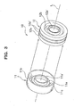
- the lip-type seal 10 is made up of a first reinforcing member 11 formed annularly and a first sealing member 12 formed annularly.
- the first reinforcing member 11 which is formed by subjecting a metallic plate, such as a cold-rolled steel strip or a stainless steel plate, to press working, has a wall surface part 11a that defines a circular hole 11a' through which the rotational shaft S is passed, a cylindrical part 11b that is bent from the outer edge of the wall surface part 11a and that extends in an axial direction L, and an inner cylindrical part 11c that is interposed between the wall surface part 11a and the cylindrical part 11b and that is formed coaxially with the cylindrical part 11b inside the cylindrical part 11b.
- a metallic plate such as a cold-rolled steel strip or a stainless steel plate
- the first sealing member 12 is molded out of rubber such as H-NBR, and has an annular (cylindrical) base 12a that is joined to a wall surface H1 of the housing H and that extends in the axial direction L, a first lip part 12b that extends almost conical inwardly in the radial direction from the base 12a and that defines a circular inner edge 12b' coming into contact with the rotational shaft S, and an annular (cylindrical) concave part 12c that has an opening 12c' at its end face (on the side of the air A) in the base 12a and that is formed to receive the cylindrical part 11b, as shown in Fig. 3 and Fig. 4.
- an annular (cylindrical) base 12a that is joined to a wall surface H1 of the housing H and that extends in the axial direction L
- a first lip part 12b that extends almost conical inwardly in the radial direction from the base 12a and that defines a circular inner edge 12b' coming into contact
- the first reinforcing member 11 is formed so that the wall surface part 11a can adjoin (can come into close contact with) a root area 12b" of a first lip part 12b in the axial direction L, whereby the first lip part 12b is prevented from being deformed inwardly in the radial direction beyond the allowable limits. Further, the first reinforcing member 11 is formed so that the inner cylindrical part 11c can be fitted into the inside of the base 12a, and a part 12a" of the base 12a (i.e., a part defined by the concave part 12c and the inner circumferential surface of the base 12a) can be supported radially in a sandwiched manner in cooperation with the cylindrical part 11b. As a result, the first reinforcing member 11 and the first sealing member 12 are reliably attached to each other.
- the first sealing member 12 is provided with two projection parts 12a' that annularly protrude outwardly in the radial direction on the outer peripheral surface of the base 12a, whereby the adhesion with the wall surface H1 is improved.
- the first reinforcing member 11 and the first sealing member 12 are arranged in the axial direction L as shown in Fig. 3, and the cylindrical part 11b of the first reinforcing member 11 is fitted into the annular concave part 12c formed on the base 12a of the first sealing member 12. Attaching is completed with ease merely by fitting the cylindrical part 11b into the annular concave part 12c without a caulking process or an adhesive. In this state, the base 12a is reliably sandwiched between the cylindrical part 11b and the inner cylindrical part 11c, so that these components are reliably attached to each other.
- the first reinforcing member 11 and the first sealing member 12 can be reliably separated merely by pulling out the cylindrical part 11b from the annular concave part 12c.
- the first reinforcing member 11 has the wall surface part 11a exposed and integrally formed with the cylindrical part 11b that is fitted and buried in the concave part 12c of the first sealing member 12, the components can be easily disassembled by gripping the wall surface part 11a, for example, while putting a finger into the circular hole 11a' or while using a tool.
- the rotational shaft S is passed so that the inner edge 12b' of the first lip part 12b comes into contact with the outer peripheral surface of the rotational shaft S as shown in Fig. 4, the base 12a of the first sealing member 12 is then fitted to the wall surface H1, and a snap ring R is attached so as to come into contact with the first sealing member 12 in a state in which the end face of the first reinforcing member 11 is in contact with a wall surface H2.
- the snap ring R has an inclined surface with an inclination angle ⁇ of about 10 to 20 degrees, preferably 15 degrees, and presses the lip-type seal 10 against the wall surface H2 by being fitted into an annular groove H3 formed to likewise have an inclined surface in the housing H.
- the inner cylindrical part 11c is provided in the first reinforcing member 11.
- the present invention may have a structure in which the cylindrical part 11b is directly provided to be bent from the outer edge of the wall surface part 11a, without providing the inner cylindrical part 11c.
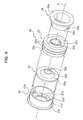
- Fig. 5 and Fig. 6 show another embodiment of the lip-type seal according to the present invention, in which a second sealing member and a second reinforcing member are added to the components used in the foregoing embodiment.
- the same reference symbol is given to the same constituent element as in the foregoing embodiment, and overlapping description thereof is omitted.
- the lip-type seal 20 is made up of a first reinforcing member 21 formed annularly, a first sealing member 22 formed annularly, a second sealing member 23 sandwiched between the first reinforcing member 21 and the first sealing member 22, and a second reinforcing member 24 fitted to the first sealing member 22 on the side opposite the first reinforcing member 21.
- the first reinforcing member 21 is formed by subjecting a metallic plate, such as a cold-rolled steel strip or a stainless steel plate, to press working, and, as shown in Fig. 5 and Fig. 6, has a wall surface part 21a that defines a circular hole 21a' through which a rotational shaft S is passed, a cylindrical part 21b that is bent from the outer edge of the wall surface part 21a and that extends in the axial direction L, and a collar part 21c formed by widening its radius in the bent region between the wall surface part 21a and the cylindrical part 21b.
- a metallic plate such as a cold-rolled steel strip or a stainless steel plate
- the wall surface part 21a is provided with a plurality of projections 21a" that serve as rotation stoppers arranged in the circumferential direction on the surface to which the second sealing member 23 is joined.
- the projections 21a" can effectively restrict the rotation of the second sealing member 23 although the second sealing member 23 is merely supported in a sandwiched manner.
- the first sealing member 22 is molded out of rubber such as H-NBR, and, as shown in Fig. 5 and Fig. 6, has an annular (cylindrical) base 22a that is joined to a wall surface H1 of the housing H and that extends in the axial direction L, a first lip part 22b that extends almost conical inwardly in the radial direction from the base 22a and that defines a circular inner edge 22b' coming into contact with the rotational shaft S, and an annular (cylindrical) concave part 22c that has an opening 22c' at its end face (on the side of the air A) in the base 22a and that is formed to receive the cylindrical part 21b.
- an annular (cylindrical) base 22a that is joined to a wall surface H1 of the housing H and that extends in the axial direction L
- a first lip part 22b that extends almost conical inwardly in the radial direction from the base 22a and that defines a circular inner edge 22b' coming into
- Two projection parts 22a' that annularly protrude outwardly in the radial direction are formed on the outer peripheral surface of the base 22a, whereby the adhesion with the wall surface H1 is improved as in the foregoing embodiment.
- the second sealing member 23 is molded out of resin such as tetrafluoroethylene resin, and, as shown in Fig. 5 and Fig. 6, has a to-be-sandwiched part 23a flatly formed with a circular outline so as to be sandwiched between the wall surface part 21a and the root area 22b" of the first lip part 22b and a second lip part 23b that extends almost conical inwardly in the radial direction from the to-be-sandwiched part 23a and that defines a circular inner edge 23b' coming into contact with the rotational shaft S.
- resin such as tetrafluoroethylene resin
- the second reinforcing member 24 is formed by subjecting a metallic plate, such as a cold-rolled steel strip or a stainless steel plate, to press working, and, as shown in Fig. 5 and Fig. 6, has a flat annular wall surface part 24a that is brought into contact with the end face (on the side of the internal space B) of the base 22a in the axial direction L, a cylindrical part 24b that is bent from the outer edge of the annular wall surface part 24a and that extends in the axial direction L, and a contact part 24b' that is vertically bent at the end of the cylindrical part 24b and that comes into contact with the root area 22b" of the first lip part 22b.
- a metallic plate such as a cold-rolled steel strip or a stainless steel plate
- the first reinforcing member 21, the second sealing member 23, the first sealing member 22, and the second reinforcing member 24 are arranged in the axial direction L as shown in Fig. 5, the cylindrical part 21b of the first reinforcing member 21 is then fitted into the concave part 22a of the first sealing member 22 in such a way as to sandwich the to-be-sandwiched part 23a of the second sealing member 23 therebetween, and the cylindrical part 24b of the second reinforcing member 24 is fitted into the inside of the base 22a.
- the first reinforcing member 21, the first sealing member 22, the second sealing member 23, and the second reinforcing member 24 are completely assembled merely by fitting these components thereinto without a caulking process or an adhesive.
- the contact part 24b' of the second reinforcing member 24 reliably supports the second sealing member 23 (the to-be-sandwiched part 23a) in a sandwiched manner in cooperation with the wall surface part 21a of the first reinforcing member 21 while restricting the deformation of the root area 22b" of the first lip part 22b. Further, the projections 21a" of the wall surface part 21a restricts the rotation of the second sealing member 23 (to-be-sandwiched part 23a), whereby the second sealing member 23 is reliably assembled to a predetermined position.
- a part 22a" of the base 22a (i.e., a part defined by the concave part 22c and the inner circumferential surface of the base 22a) is reliably sandwiched in the radial direction between the cylindrical part 21b of the first reinforcing member 21 and the cylindrical part 24b of the second reinforcing member 24, so that the first reinforcing member 21, the first sealing member 22, and the second reinforcing member 24 are reliably assembled to each other.
- the components can be reliably separated from each other merely by pulling out the cylindrical part 21b of the first reinforcing member 21 from the concave part 22c and by pulling out the cylindrical part 24b of the second reinforcing member 24 from the inside of the base 22a.
- the first reinforcing member 21 has the wall surface part 21a exposed and integrally formed with the cylindrical part 21b that is fitted and buried in the concave part 22c, the components can be easily disassembled by gripping the wall surface part 21a, for example, while putting a finger into the circular hole 21a' or using a tool.
- a snap ring R is attached as shown in Fig. 6 in the same way as in the foregoing embodiment.
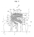
- Another method may be carried out as follows. Instead of the snap ring R, another member H' disposed in the housing H (or, alternatively, a part of the housing H) is brought into contact with the annular wall surface part 24a of the second reinforcing member 24 from the axial direction L, and the lip-type seal 20 is pressed against the wall surface H2 as shown in Fig. 7.
- the projection 21a" is provided on the wall surface part 21a as a rotation stopper that restricts the rotation of the second sealing member 23.
- a similar projection may be molded integrally with the root area 22b" of the first sealing member 22.
- the contact part 24b' is provided in the second reinforcing member 24.
- the cylindrical part 24b may be shortened, and the contact part 24b' may be removed as long as the second sealing member 23 is reliably sandwiched.
- the cylindrical part 24b may be fitted to the inside of the base 22a in a slightly loosened state.
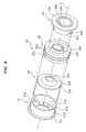
- Fig. 8 and Fig. 9 show still another embodiment of the lip-type seal according to the present invention, in which the second reinforcing member shown in the above embodiment of Fig. 5 and Fig. 6 is changed. Therefore, the same reference symbol is given to the same structure as in the foregoing embodiment, and overlapping description thereof is omitted.
- the second reinforcing member 24' has a restriction part 24c formed cylindrically so as to be bent further inwardly from the contact part 24b' and to extend in the axial direction L, in addition to the annular wall surface part 24a, the cylindrical part 24b, and the contact part 24b', as shown in Fig. 8 and Fig. 9.
- the restriction part 24c is formed cylindrically so as to surround the first lip part 22b outside in the radial direction of the first lip part 22b in the assembled state, whereby the first lip part 22b is prevented from being deformed outwardly beyond the allowable limits. Therefore, a desired sealing capability can be secured without influence of fluids in the internal space B.
- this lip-type seal 20' the components can be easily assembled and disassembled while securing such a desired sealing capability.
- Fig. 10 and Fig. 11 show still another embodiment of the lip-type seal according to the present invention, in which the first sealing member shown in the embodiment of Fig. 5 and Fig. 6 is partially changed and in which an annular spring 25 is added. Therefore, the same reference symbol is given to the same structure as in the foregoing embodiment, and overlapping description thereof is omitted.
- the first sealing member 22' has an annular groove 22b"' formed in the outer peripheral surface of the first lip part 22b, in addition to the annular base 22a, the first lip part 22b, the annular concave part 22c, and the opening 22c'.
- the annular spring 25 is detachably attached to the groove 22b"'.
- the spring 25 always exerts a predetermined urging force onto the first lip part 22b inwardly in the radial direction, and prevents the first lip part 22b from being deformed outwardly beyond the allowable limits. Therefore, a desired sealing capability can be secured without influence, for example, of fluids in the internal space B.
- this lip-type seal 20'' the components can be easily assembled and disassembled while securing such a desired sealing capability.
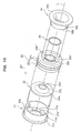
- Fig. 12 and Fig. 13 show still another embodiment of the lip-type seal according to the present invention, in which a third reinforcing member 26 is added to the components shown in the embodiment of Fig. 5 and Fig. 6. Therefore, the same reference symbol is given to the same structure as in the foregoing embodiment, and overlapping description thereof is omitted.
- the third reinforcing member 26 is formed by subjecting a metallic plate, such as a cold-rolled steel strip or a stainless steel plate, to press working, and, as shown in Fig. 12 and Fig. 13, has a substantially flat to-be-sandwiched part 26a having a circular outline so as to be sandwiched between the to-be-sandwiched part 23a of the second sealing member 23 and the root area 22b" of the first sealing member 22 and a slant surface part 26b that extends almost conical inwardly in the radial direction from the to-be-sandwiched part 26a and that defines a circular hole 26b' through which the rotational shaft S is passed.
- a metallic plate such as a cold-rolled steel strip or a stainless steel plate
- the slant surface part 26b is formed to adjoin (come into close contact with) the first lip part 22b of the first sealing member 22, whereby the first lip part 22b is prevented from being deformed inwardly beyond the allowable limits. Therefore, a desired sealing capability can be secured without influence, for example, of fluids in the internal space B.
- the components can be easily assembled and disassembled while securing such a desired sealing capability.
- the lip-type seals 10, 20, 20', 20" , and 20''' are applied to the compressor C that serves as a part of an air conditioning system, for example, of a vehicle.
- the lip-type seal can be applied to any apparatus or electrical appliance if these devices include a rotational shaft and a housing which supports the rotational shaft.
- the lip-type seal of the present invention is easily attached, detached, and sorted while maintaining its desired sealing capability, and hence a recycling process can be easily carried out. Therefore, the lip-type seal is useful in an apparatus or electrical appliance that is required to seal the outer periphery of its rotational shaft with such a lip-type seal.
Landscapes
- Engineering & Computer Science (AREA)
- General Engineering & Computer Science (AREA)
- Mechanical Engineering (AREA)
- Sealing With Elastic Sealing Lips (AREA)
- Sealing Devices (AREA)
Abstract
Description
Claims (10)
- A lip-type seal with which an outer periphery of a rotational shaft supported by a predetermined housing is sealed, the lip-type seal comprising:a first reinforcing member formed annularly, the first reinforcing member including a wall surface part defining a hole through which the rotational shaft is passed and a cylindrical part bent from an outer edge of the wall surface part, anda first sealing member, the first sealing member including an annular base that is joined to the housing, a first lip part that extends almost conical inwardly in a radial direction from the base and that comes into contact with the rotational shaft, and an annular concave part formed on the base so as to detachably fit the cylindrical part.
- The lip-type seal as set forth in Claim 1, wherein the first reinforcing member has an inner cylindrical part that supports the base in a sandwiched manner from the inside in cooperation with the cylindrical part, and the wall surface part extends from the inner cylindrical part.
- The lip-type seal as set forth in Claim. 2, wherein the wall surface part is contiguous to a root area of the first lip part in an axial direction of the rotational shaft.
- The lip-type seal as set forth in Claim 1, further comprising:a second sealing member that is sandwiched between the first reinforcing member and the first sealing member; anda second reinforcing member that is formed annularly and that is fitted to the first sealing member on a side opposite the first reinforcing member,the second sealing member including:a to-be-sandwiched part that is sandwiched between the wall surface part and the root area of the first lip part; anda second lip part that extends almost conical from the to-be-sandwiched part inwardly in a radial direction and that comes into contact with the rotational shaft,the second reinforcing member including:an annular wall surface part that is brought into contact with the base in the axial direction of the rotational shaft; anda cylindrical part that is bent from the inner edge of the annular wall surface and that is fitted to the inside of the base.
- The lip-type seal as set forth in Claim 4, wherein the first sealing member is made of rubber, and
the second sealing member is made of resin. - The lip-type seal as set forth in Claim 4, wherein the cylindrical part of the second reinforcing member has a contact part that comes into contact with the root area of the first lip part in the axial direction of the rotational shaft.
- The lip-type seal as set forth in Claim 4, wherein the wall surface part of the first reinforcing member is provided with a rotation stopper that restricts the rotation of the second sealing member.
- The lip-type seal as set forth in Claim 4, wherein the second reinforcing member has a restriction part that is bent from the cylindrical part inwardly so as to be cylindrical and that restricts deformation of the first lip part caused outwardly in the radial direction of the first lip part within a predetermined range.
- The lip-type seal as set forth in Claim 4, wherein the first sealing member is detachably provided with an annular spring that exerts an urging force inwardly in the radial direction in an outer peripheral area of the first lip part.
- The lip-type seal as set forth in Claim 4, wherein a third reinforcing member that is formed annularly and that restricts deformation of the first lip part caused inwardly in the radial direction of the first lip part within a predetermined range is sandwiched between the first sealing member and the second sealing member.
Applications Claiming Priority (3)
| Application Number | Priority Date | Filing Date | Title |
|---|---|---|---|
| JP2003052078 | 2003-02-27 | ||
| JP2003052078 | 2003-02-27 | ||
| PCT/JP2004/000936 WO2004076894A1 (en) | 2003-02-27 | 2004-01-30 | Lip-type seal |
Publications (3)
| Publication Number | Publication Date |
|---|---|
| EP1598579A1 true EP1598579A1 (en) | 2005-11-23 |
| EP1598579A4 EP1598579A4 (en) | 2006-05-17 |
| EP1598579B1 EP1598579B1 (en) | 2008-05-14 |
Family
ID=32923388
Family Applications (1)
| Application Number | Title | Priority Date | Filing Date |
|---|---|---|---|
| EP04706837A Expired - Lifetime EP1598579B1 (en) | 2003-02-27 | 2004-01-30 | Lip-type seal |
Country Status (7)
| Country | Link |
|---|---|
| US (1) | US7344140B2 (en) |
| EP (1) | EP1598579B1 (en) |
| JP (1) | JP4634299B2 (en) |
| KR (1) | KR101051110B1 (en) |
| CN (1) | CN100392293C (en) |
| DE (1) | DE602004013730D1 (en) |
| WO (1) | WO2004076894A1 (en) |
Cited By (9)
| Publication number | Priority date | Publication date | Assignee | Title |
|---|---|---|---|---|
| EP1900982A1 (en) * | 2006-09-15 | 2008-03-19 | Mitsubishi Cable Industries, Ltd. | Rotation shaft seal |
| EP1982097A2 (en) * | 2006-02-07 | 2008-10-22 | Federal-Mogul Corporation | Method of retaining a dynamic seal in a bore that has a draft |
| EP2053287A1 (en) * | 2007-10-25 | 2009-04-29 | Mitsubishi Cable Industries, Ltd. | Rotation shaft seal |
| EP2233799A1 (en) | 2009-03-23 | 2010-09-29 | Bal Seal Engineering, Inc. | Seal assemblies for movable and static shafts |
| EP2233798A1 (en) * | 2009-03-23 | 2010-09-29 | Bal Seal Engineering, Inc. | Interlocking composite seals |
| EP2767723A3 (en) * | 2013-02-14 | 2015-09-02 | DORMA Deutschland GmbH | Housing component |
| US9163731B2 (en) | 2008-05-15 | 2015-10-20 | Eagle Industry Co., Ltd. | Lip type seal |
| EP2889518A4 (en) * | 2012-08-23 | 2016-04-06 | Eagle Ind Co Ltd | Sealing device |
| US9357684B2 (en) | 2013-09-24 | 2016-05-31 | Bal Seal Engineering, Inc. | Spring assemblies with spring energized seal members and related methods |
Families Citing this family (29)
| Publication number | Priority date | Publication date | Assignee | Title |
|---|---|---|---|---|
| JP4865571B2 (en) * | 2004-12-28 | 2012-02-01 | イーグル工業株式会社 | Shaft seal device |
| US7854432B2 (en) * | 2005-02-24 | 2010-12-21 | Freudenberg-Nok General Partnership | Dynamic seal |
| US20060290068A1 (en) * | 2005-06-27 | 2006-12-28 | Freudenberg-Nok General Partnership | Radially assembled seal |
| JP4579110B2 (en) * | 2005-09-07 | 2010-11-10 | 三菱電線工業株式会社 | Rotating shaft seal |
| JP4822897B2 (en) * | 2006-03-28 | 2011-11-24 | 三菱電線工業株式会社 | Rotating shaft seal |
| US20090166977A1 (en) * | 2006-07-20 | 2009-07-02 | Carl Freudenberg Kg | Seal |
| US7753377B2 (en) * | 2007-01-29 | 2010-07-13 | Freudenberg-Nok General Partnership | Shaft seal having shaft offset compensating capability |
| JP4875597B2 (en) | 2007-11-28 | 2012-02-15 | イーグル工業株式会社 | Lip type seal |
| WO2009094598A1 (en) * | 2008-01-25 | 2009-07-30 | Kenneth Krohn | Device for connecting to ducts of various sizes and shapes |
| TWI331123B (en) * | 2008-03-06 | 2010-10-01 | Gudeng Prec Ind Co Ltd | Reticle pod and method for keeping reticle clean and dry |
| US8096559B2 (en) * | 2008-05-23 | 2012-01-17 | Bal Seal Engineering, Inc. | Rotary seals |
| GB0814616D0 (en) * | 2008-08-11 | 2008-09-17 | Crane John Uk Ltd | Improvements in and relating to spring energised plastic seals |
| CN101842622B (en) | 2008-11-27 | 2014-01-15 | 伊格尔工业股份有限公司 | Lip seal |
| US8684362B2 (en) * | 2009-08-12 | 2014-04-01 | Bal Seal Engineering, Inc. | Cartridge seal assemblies and associated methods |
| US9746081B2 (en) * | 2009-08-25 | 2017-08-29 | Freudenberg-Nok General Partnership | Low load offset seal |
| WO2011030585A1 (en) | 2009-09-09 | 2011-03-17 | イーグル工業株式会社 | Lip type seal |
| CN102200208B (en) * | 2010-03-24 | 2015-03-25 | 仓敷化工株式会社 | Flexible joint |
| CN104613261A (en) * | 2010-03-24 | 2015-05-13 | 仓敷化工株式会社 | Flexible joint |
| CN102959286B (en) * | 2010-09-11 | 2015-05-27 | 伊格尔工业股份有限公司 | Shaft sealing device |
| JP2012097706A (en) * | 2010-11-05 | 2012-05-24 | Hitachi Automotive Systems Ltd | Actuator for variable valve device |
| US8556270B2 (en) * | 2011-06-17 | 2013-10-15 | Federal-Mogul Corporation | Radial shaft seal, radial shaft seal assembly and method of installation |
| JP5969331B2 (en) * | 2012-09-05 | 2016-08-17 | 光洋シーリングテクノ株式会社 | Sealing device mounting structure and sealing device |
| EP2952788B1 (en) * | 2013-01-29 | 2017-10-04 | Eagle Industry Co., Ltd. | Sealing device |
| JP6132146B2 (en) * | 2013-05-27 | 2017-05-24 | Nok株式会社 | Sealing device |
| US9695937B2 (en) | 2014-02-04 | 2017-07-04 | Freudenberg-Nok General Partnership | Energy saving seal with vacuum induced counter-balance and rocking feature |
| US9714710B2 (en) | 2014-02-04 | 2017-07-25 | Freudenberg-Nok General Partnership | Energy saving self-contact seal with pushing bead |
| US9759330B2 (en) | 2014-02-04 | 2017-09-12 | Freudenberg-Nok General Partnership | Energy saving seal with rocking dust lip |
| JP6351103B2 (en) * | 2014-08-27 | 2018-07-04 | 株式会社マキタ | Work tools |
| CN104477157A (en) * | 2014-12-20 | 2015-04-01 | 芜湖盛力科技股份有限公司 | Air-assisted hydraulic air booster pump for magnetically levitated train |
Citations (2)
| Publication number | Priority date | Publication date | Assignee | Title |
|---|---|---|---|---|
| US5368312A (en) * | 1992-07-30 | 1994-11-29 | Deutsche Aerospace Ag | Arrangement for the sealing-off of metallic cylindrical bodies |
| WO2002042666A1 (en) * | 2000-11-27 | 2002-05-30 | Luk Fahrzeug-Hydraulik Gmbh & Co.Kg | Rotary shaft seal and use thereof |
Family Cites Families (22)
| Publication number | Priority date | Publication date | Assignee | Title |
|---|---|---|---|---|
| US2213116A (en) * | 1939-01-28 | 1940-08-27 | Victor Mfg & Gasket Co | Flexible oil seal |
| US2750214A (en) * | 1952-01-19 | 1956-06-12 | Peter D Bermingham | Two-piece fluid seal |
| US2819100A (en) * | 1955-01-10 | 1958-01-07 | Marlin Rockwell Corp | Bearing seals |
| US2950135A (en) * | 1956-09-07 | 1960-08-23 | Chicago Rawhide Mfg Co | Oil seal |
| JPS348017Y1 (en) * | 1957-03-11 | 1959-05-27 | ||
| US3284145A (en) * | 1965-06-07 | 1966-11-08 | Mcgill Mfg Company Inc | Sealed anti-friction bearing |
| US3362719A (en) * | 1965-10-23 | 1968-01-09 | Ramsey Corp | Inserts for rotary shaft seals |
| US3940155A (en) * | 1974-09-20 | 1976-02-24 | Borg-Warner Corporation | Elastomeric seal |
| USRE30223E (en) * | 1976-02-11 | 1980-03-04 | The Mechanex Corporation | Lubricant seal |
| JPS6078168A (en) * | 1983-10-04 | 1985-05-02 | Nok Corp | Seal |
| USRE34874E (en) * | 1984-11-21 | 1995-03-14 | Precision Tube Bending, Inc. | Seal with two sealing portions having flange receiving opening therebetween |
| KR890004033B1 (en) * | 1985-04-16 | 1989-10-16 | 에누오우케이 가부시끼가이샤 | Radial oil sealing |
| JPH028565A (en) * | 1988-01-11 | 1990-01-12 | Taiho Kogyo Co Ltd | Lip seal device |
| JPH08247294A (en) * | 1995-03-15 | 1996-09-24 | Nok Corp | Sealing device for high pressure |
| JP3591221B2 (en) * | 1997-05-16 | 2004-11-17 | Nok株式会社 | Sealing device |
| US6050572A (en) * | 1998-03-09 | 2000-04-18 | Bal Seal Engineering Company, Inc. | Rotary cartridge seals with retainer |
| JP2000110947A (en) * | 1998-10-02 | 2000-04-18 | Toyota Autom Loom Works Ltd | Shaft seal device for compressor |
| US6367811B1 (en) * | 1998-11-24 | 2002-04-09 | Mitsubishi Cable Industries, Ltd. | Rotation shaft seal |
| WO2000079157A1 (en) * | 1999-06-18 | 2000-12-28 | Nok Corporation | Lip-type high-pressure seal |
| JP3875824B2 (en) * | 2000-03-17 | 2007-01-31 | イーグル工業株式会社 | Lip type seal |
| JP2002364759A (en) * | 2001-06-06 | 2002-12-18 | Toyota Industries Corp | Lip seal |
| JP2003120823A (en) * | 2001-10-19 | 2003-04-23 | Eagle Ind Co Ltd | Seal device |
-
2004
- 2004-01-30 CN CNB2004800047943A patent/CN100392293C/en not_active Expired - Fee Related
- 2004-01-30 WO PCT/JP2004/000936 patent/WO2004076894A1/en active IP Right Grant
- 2004-01-30 JP JP2005502820A patent/JP4634299B2/en not_active Expired - Fee Related
- 2004-01-30 US US10/542,751 patent/US7344140B2/en not_active Expired - Lifetime
- 2004-01-30 DE DE602004013730T patent/DE602004013730D1/en not_active Expired - Lifetime
- 2004-01-30 KR KR1020057012723A patent/KR101051110B1/en active IP Right Grant
- 2004-01-30 EP EP04706837A patent/EP1598579B1/en not_active Expired - Lifetime
Patent Citations (2)
| Publication number | Priority date | Publication date | Assignee | Title |
|---|---|---|---|---|
| US5368312A (en) * | 1992-07-30 | 1994-11-29 | Deutsche Aerospace Ag | Arrangement for the sealing-off of metallic cylindrical bodies |
| WO2002042666A1 (en) * | 2000-11-27 | 2002-05-30 | Luk Fahrzeug-Hydraulik Gmbh & Co.Kg | Rotary shaft seal and use thereof |
Non-Patent Citations (1)
| Title |
|---|
| See also references of WO2004076894A1 * |
Cited By (12)
| Publication number | Priority date | Publication date | Assignee | Title |
|---|---|---|---|---|
| EP1982097A2 (en) * | 2006-02-07 | 2008-10-22 | Federal-Mogul Corporation | Method of retaining a dynamic seal in a bore that has a draft |
| EP1982097A4 (en) * | 2006-02-07 | 2012-06-20 | Federal Mogul Corp | Method of retaining a dynamic seal in a bore that has a draft |
| EP1900982A1 (en) * | 2006-09-15 | 2008-03-19 | Mitsubishi Cable Industries, Ltd. | Rotation shaft seal |
| EP2053287A1 (en) * | 2007-10-25 | 2009-04-29 | Mitsubishi Cable Industries, Ltd. | Rotation shaft seal |
| US9163731B2 (en) | 2008-05-15 | 2015-10-20 | Eagle Industry Co., Ltd. | Lip type seal |
| EP2233799A1 (en) | 2009-03-23 | 2010-09-29 | Bal Seal Engineering, Inc. | Seal assemblies for movable and static shafts |
| EP2233798A1 (en) * | 2009-03-23 | 2010-09-29 | Bal Seal Engineering, Inc. | Interlocking composite seals |
| US8544850B2 (en) | 2009-03-23 | 2013-10-01 | Bal Seal Engineering, Inc. | Seal assemblies for movable and static shafts |
| US10247307B2 (en) | 2009-03-23 | 2019-04-02 | Bal Seal Engineering, Inc. | Interlocking composite seals |
| EP2889518A4 (en) * | 2012-08-23 | 2016-04-06 | Eagle Ind Co Ltd | Sealing device |
| EP2767723A3 (en) * | 2013-02-14 | 2015-09-02 | DORMA Deutschland GmbH | Housing component |
| US9357684B2 (en) | 2013-09-24 | 2016-05-31 | Bal Seal Engineering, Inc. | Spring assemblies with spring energized seal members and related methods |
Also Published As
| Publication number | Publication date |
|---|---|
| JP4634299B2 (en) | 2011-02-16 |
| US7344140B2 (en) | 2008-03-18 |
| US20060290069A1 (en) | 2006-12-28 |
| JPWO2004076894A1 (en) | 2006-06-08 |
| EP1598579B1 (en) | 2008-05-14 |
| KR101051110B1 (en) | 2011-07-22 |
| EP1598579A4 (en) | 2006-05-17 |
| CN100392293C (en) | 2008-06-04 |
| CN1751195A (en) | 2006-03-22 |
| WO2004076894A1 (en) | 2004-09-10 |
| DE602004013730D1 (en) | 2008-06-26 |
| KR20050103469A (en) | 2005-10-31 |
Similar Documents
| Publication | Publication Date | Title |
|---|---|---|
| US7344140B2 (en) | Lip-type seal | |
| US20070196960A1 (en) | Semiconductor device and method of manufacturing the same | |
| JP4958768B2 (en) | Shaft seal assembly | |
| US8366117B2 (en) | Sealing device | |
| US6676527B2 (en) | Attachment structure for joint boot | |
| EP2889518B1 (en) | Sealing device | |
| US20060249915A1 (en) | Shaft seal having integrated removal feature | |
| US9644745B2 (en) | Mechanical seal | |
| JPS58501685A (en) | Fixing rigid inserts in flexible materials | |
| US4300773A (en) | Sealing device | |
| JP2000033206A (en) | Filter apparatus | |
| US4906008A (en) | Mechanical seal | |
| US20040052662A1 (en) | Anti - leak device in a fan | |
| EP1290365B1 (en) | Seal | |
| JP3022828B2 (en) | Antenna structure | |
| JPH0641020Y2 (en) | Unitized seal | |
| JPH11148561A (en) | Oil seal | |
| JPH07317796A (en) | Boots for constant velocity universal joint | |
| EP1686296A1 (en) | Lip seal and manufacturing method thereof | |
| JP2000033205A (en) | Filter apparatus | |
| JP2002362172A (en) | Seal structure of fuel system auxiliary machine | |
| JPH10274338A (en) | Pressure resistant oil seal | |
| JP2004308803A (en) | Metal seal assembling structure and its assembling method | |
| JP2001027329A (en) | Sealing device | |
| JP2006083975A (en) | Mounting structure of sealing device |
Legal Events
| Date | Code | Title | Description |
|---|---|---|---|
| PUAI | Public reference made under article 153(3) epc to a published international application that has entered the european phase |
Free format text: ORIGINAL CODE: 0009012 |
|
| 17P | Request for examination filed |
Effective date: 20050727 |
|
| AK | Designated contracting states |
Kind code of ref document: A1 Designated state(s): AT BE BG CH CY CZ DE DK EE ES FI FR GB GR HU IE IT LI LU MC NL PT RO SE SI SK TR |
|
| AX | Request for extension of the european patent |
Extension state: AL LT LV MK |
|
| A4 | Supplementary search report drawn up and despatched |
Effective date: 20060404 |
|
| DAX | Request for extension of the european patent (deleted) | ||
| RBV | Designated contracting states (corrected) |
Designated state(s): DE FR |
|
| 17Q | First examination report despatched |
Effective date: 20060627 |
|
| GRAP | Despatch of communication of intention to grant a patent |
Free format text: ORIGINAL CODE: EPIDOSNIGR1 |
|
| GRAS | Grant fee paid |
Free format text: ORIGINAL CODE: EPIDOSNIGR3 |
|
| GRAA | (expected) grant |
Free format text: ORIGINAL CODE: 0009210 |
|
| AK | Designated contracting states |
Kind code of ref document: B1 Designated state(s): DE FR |
|
| REF | Corresponds to: |
Ref document number: 602004013730 Country of ref document: DE Date of ref document: 20080626 Kind code of ref document: P |
|
| PLBE | No opposition filed within time limit |
Free format text: ORIGINAL CODE: 0009261 |
|
| STAA | Information on the status of an ep patent application or granted ep patent |
Free format text: STATUS: NO OPPOSITION FILED WITHIN TIME LIMIT |
|
| 26N | No opposition filed |
Effective date: 20090217 |
|
| PGFP | Annual fee paid to national office [announced via postgrant information from national office to epo] |
Ref country code: FR Payment date: 20100208 Year of fee payment: 7 |
|
| REG | Reference to a national code |
Ref country code: FR Ref legal event code: ST Effective date: 20110930 |
|
| PG25 | Lapsed in a contracting state [announced via postgrant information from national office to epo] |
Ref country code: FR Free format text: LAPSE BECAUSE OF NON-PAYMENT OF DUE FEES Effective date: 20110131 |
|
| PGFP | Annual fee paid to national office [announced via postgrant information from national office to epo] |
Ref country code: DE Payment date: 20200114 Year of fee payment: 17 |
|
| REG | Reference to a national code |
Ref country code: DE Ref legal event code: R119 Ref document number: 602004013730 Country of ref document: DE |
|
| PG25 | Lapsed in a contracting state [announced via postgrant information from national office to epo] |
Ref country code: DE Free format text: LAPSE BECAUSE OF NON-PAYMENT OF DUE FEES Effective date: 20210803 |