EP1598530A1 - Assembly of a plurality of collars and variable valve actuation mechanisms on a shaft - Google Patents
Assembly of a plurality of collars and variable valve actuation mechanisms on a shaft Download PDFInfo
- Publication number
- EP1598530A1 EP1598530A1 EP05252830A EP05252830A EP1598530A1 EP 1598530 A1 EP1598530 A1 EP 1598530A1 EP 05252830 A EP05252830 A EP 05252830A EP 05252830 A EP05252830 A EP 05252830A EP 1598530 A1 EP1598530 A1 EP 1598530A1
- Authority
- EP
- European Patent Office
- Prior art keywords
- variable valve
- valve lift
- lift mechanisms
- axial direction
- shaft
- Prior art date
- Legal status (The legal status is an assumption and is not a legal conclusion. Google has not performed a legal analysis and makes no representation as to the accuracy of the status listed.)
- Granted
Links
Images











Classifications
-
- F—MECHANICAL ENGINEERING; LIGHTING; HEATING; WEAPONS; BLASTING
- F01—MACHINES OR ENGINES IN GENERAL; ENGINE PLANTS IN GENERAL; STEAM ENGINES
- F01L—CYCLICALLY OPERATING VALVES FOR MACHINES OR ENGINES
- F01L13/00—Modifications of valve-gear to facilitate reversing, braking, starting, changing compression ratio, or other specific operations
- F01L13/0015—Modifications of valve-gear to facilitate reversing, braking, starting, changing compression ratio, or other specific operations for optimising engine performances by modifying valve lift according to various working parameters, e.g. rotational speed, load, torque
- F01L13/0063—Modifications of valve-gear to facilitate reversing, braking, starting, changing compression ratio, or other specific operations for optimising engine performances by modifying valve lift according to various working parameters, e.g. rotational speed, load, torque by modification of cam contact point by displacing an intermediate lever or wedge-shaped intermediate element, e.g. Tourtelot
-
- F—MECHANICAL ENGINEERING; LIGHTING; HEATING; WEAPONS; BLASTING
- F01—MACHINES OR ENGINES IN GENERAL; ENGINE PLANTS IN GENERAL; STEAM ENGINES
- F01L—CYCLICALLY OPERATING VALVES FOR MACHINES OR ENGINES
- F01L1/00—Valve-gear or valve arrangements, e.g. lift-valve gear
- F01L1/02—Valve drive
- F01L1/022—Chain drive
-
- F—MECHANICAL ENGINEERING; LIGHTING; HEATING; WEAPONS; BLASTING
- F01—MACHINES OR ENGINES IN GENERAL; ENGINE PLANTS IN GENERAL; STEAM ENGINES
- F01L—CYCLICALLY OPERATING VALVES FOR MACHINES OR ENGINES
- F01L1/00—Valve-gear or valve arrangements, e.g. lift-valve gear
- F01L1/02—Valve drive
- F01L1/04—Valve drive by means of cams, camshafts, cam discs, eccentrics or the like
- F01L1/047—Camshafts
- F01L1/053—Camshafts overhead type
-
- F—MECHANICAL ENGINEERING; LIGHTING; HEATING; WEAPONS; BLASTING
- F01—MACHINES OR ENGINES IN GENERAL; ENGINE PLANTS IN GENERAL; STEAM ENGINES
- F01L—CYCLICALLY OPERATING VALVES FOR MACHINES OR ENGINES
- F01L1/00—Valve-gear or valve arrangements, e.g. lift-valve gear
- F01L1/12—Transmitting gear between valve drive and valve
- F01L1/18—Rocking arms or levers
- F01L1/185—Overhead end-pivot rocking arms
-
- F—MECHANICAL ENGINEERING; LIGHTING; HEATING; WEAPONS; BLASTING
- F01—MACHINES OR ENGINES IN GENERAL; ENGINE PLANTS IN GENERAL; STEAM ENGINES
- F01L—CYCLICALLY OPERATING VALVES FOR MACHINES OR ENGINES
- F01L1/00—Valve-gear or valve arrangements, e.g. lift-valve gear
- F01L1/20—Adjusting or compensating clearance
- F01L1/22—Adjusting or compensating clearance automatically, e.g. mechanically
- F01L1/24—Adjusting or compensating clearance automatically, e.g. mechanically by fluid means, e.g. hydraulically
- F01L1/2405—Adjusting or compensating clearance automatically, e.g. mechanically by fluid means, e.g. hydraulically by means of a hydraulic adjusting device located between the cylinder head and rocker arm
-
- F—MECHANICAL ENGINEERING; LIGHTING; HEATING; WEAPONS; BLASTING
- F01—MACHINES OR ENGINES IN GENERAL; ENGINE PLANTS IN GENERAL; STEAM ENGINES
- F01L—CYCLICALLY OPERATING VALVES FOR MACHINES OR ENGINES
- F01L1/00—Valve-gear or valve arrangements, e.g. lift-valve gear
- F01L1/02—Valve drive
- F01L1/04—Valve drive by means of cams, camshafts, cam discs, eccentrics or the like
- F01L1/047—Camshafts
- F01L1/053—Camshafts overhead type
- F01L2001/0537—Double overhead camshafts [DOHC]
-
- F—MECHANICAL ENGINEERING; LIGHTING; HEATING; WEAPONS; BLASTING
- F01—MACHINES OR ENGINES IN GENERAL; ENGINE PLANTS IN GENERAL; STEAM ENGINES
- F01L—CYCLICALLY OPERATING VALVES FOR MACHINES OR ENGINES
- F01L2301/00—Using particular materials
-
- F—MECHANICAL ENGINEERING; LIGHTING; HEATING; WEAPONS; BLASTING
- F01—MACHINES OR ENGINES IN GENERAL; ENGINE PLANTS IN GENERAL; STEAM ENGINES
- F01L—CYCLICALLY OPERATING VALVES FOR MACHINES OR ENGINES
- F01L2303/00—Manufacturing of components used in valve arrangements
-
- F—MECHANICAL ENGINEERING; LIGHTING; HEATING; WEAPONS; BLASTING
- F01—MACHINES OR ENGINES IN GENERAL; ENGINE PLANTS IN GENERAL; STEAM ENGINES
- F01L—CYCLICALLY OPERATING VALVES FOR MACHINES OR ENGINES
- F01L2303/00—Manufacturing of components used in valve arrangements
- F01L2303/01—Tools for producing, mounting or adjusting, e.g. some part of the distribution
-
- F—MECHANICAL ENGINEERING; LIGHTING; HEATING; WEAPONS; BLASTING
- F01—MACHINES OR ENGINES IN GENERAL; ENGINE PLANTS IN GENERAL; STEAM ENGINES
- F01L—CYCLICALLY OPERATING VALVES FOR MACHINES OR ENGINES
- F01L2305/00—Valve arrangements comprising rollers
-
- F—MECHANICAL ENGINEERING; LIGHTING; HEATING; WEAPONS; BLASTING
- F01—MACHINES OR ENGINES IN GENERAL; ENGINE PLANTS IN GENERAL; STEAM ENGINES
- F01L—CYCLICALLY OPERATING VALVES FOR MACHINES OR ENGINES
- F01L2800/00—Methods of operation using a variable valve timing mechanism
- F01L2800/13—Throttleless
-
- F—MECHANICAL ENGINEERING; LIGHTING; HEATING; WEAPONS; BLASTING
- F01—MACHINES OR ENGINES IN GENERAL; ENGINE PLANTS IN GENERAL; STEAM ENGINES
- F01L—CYCLICALLY OPERATING VALVES FOR MACHINES OR ENGINES
- F01L2820/00—Details on specific features characterising valve gear arrangements
- F01L2820/03—Auxiliary actuators
- F01L2820/032—Electric motors
Definitions
- the present invention relates to a collar for receiving a shaft for a variable valve lift mechanism in a multiple-cylinder internal combustion engine.
- variable valve actuation mechanism for an internal combustion engine.
- the variable valve actuation mechanism includes a variable valve lift mechanism, which is arranged for each cylinder to adjust the lift amount of intake and exhaust valves.
- a support pipe (rocker shaft) extends through the center of the variable valve lift mechanism.
- a control shaft is arranged in the support pipe.
- the variable valve lift mechanism is pivoted in a state supported by the support pipe. The lift amount of the valve is adjusted by moving the control shaft in the axial direction.
- the support pipes are supported by a plurality of supports arranged on a cylinder head between the variable valve lift mechanisms.
- the supports position the variable valve lift mechanisms in the axial direction.
- the valve lift mechanisms are positioned in the axial direction with high accuracy so that the movement of the control shaft adjusts the valve lift amount to be the same in every cylinder.
- the cylinder block, cylinder head, and cam carrier are formed from a light alloy or a light metal, such as aluminum, to reduce weight.
- shafts included in the variable valve actuation mechanism, such as the control shaft are not formed from a light alloy or a light metal and formed from a steel material, such as cast steel or cast iron, to meet the high strength requirements.
- the coefficient of thermal expansion differs greatly between light alloy and steel.
- the control shaft becomes shorter and changes the interval between the supports located closer to the cylinder head and cam carrier.
- This produces a difference in the relative positions of the control shaft and the variable valve lift mechanism between cylinders close to the basal end of the control shaft and cylinders close to the distal end of the control shaft. Accordingly, the lift amount differs between cylinders.
- Such difference causes difficulties for adjusting the combustion state of each cylinder with high accuracy. This may generate vibrations or deteriorate emission and cause an undesirable engine operation state.
- the rocker shaft which supports the variable valve lift mechanism, is arranged at the outer side of the control shaft.
- the rocker shaft which receives the control shaft, has a large diameter
- the variable valve lift mechanism that receives the rocker shaft is enlarged. This enlarges and increases the weight of the variable valve actuation mechanism, which would contradict the demand for a smaller and lighter internal combustion engine.
- One aspect of the present invention is a collar for receiving a shaft of a multiple cylinder engine.
- the shaft supports a plurality of variable valve lift mechanisms respectively arranged in correspondence with a plurality of cylinders.
- Each variable valve lift mechanism has an end face, and the engine includes a plurality of supports for supporting the shaft.
- the collar includes a sleeve extending in an axial direction and end portions formed integrally with the sleeve. In use, a plurality of said collars are fastened to the shaft, with the sleeve of each collar being arranged between the shaft and a corresponding one of the supports so that at least one of the end portions directly or indirectly contacts or engages the end face of one of the variable valve lift mechanisms to determine the positions of the variable valve lift mechanisms.
- variable valve actuation mechanism for use in a multiple cylinder engine.
- the variable valve actuation mechanism includes a plurality of variable valve lift mechanisms respectively arranged in association with the cylinders of the engine.
- Each variable valve lift mechanism includes an end face.
- a control shaft extends through the variable valve lift mechanisms in an axial direction.
- An actuator moves the control shaft in the axial direction and drives the variable valve lift mechanisms.
- a plurality of collars are arranged alternately with the variable valve lift mechanisms for determining the positions of the variable valve lift mechanisms with respect to one another in the axial direction.
- Each collar includes a sleeve extending in the axial direction and end portions formed integrally with the sleeve. At least one of the end portions directly or indirectly contacts the end face of one of the variable valve lift mechanisms.
- a further aspect of the present invention is a variable valve actuation mechanism for use in a multiple cylinder engine.
- the variable valve actuation mechanism includes a plurality of variable valve lift mechanisms respectively arranged in association with the cylinders of the engine.
- Each variable valve lift mechanism includes an end face.
- a control shaft extends through the variable valve lift mechanisms in an axial direction.
- An actuator moves the control shaft in the axial direction and drives the variable valve lift mechanisms.
- a plurality of collars are arranged alternately with the variable valve lift mechanisms for determining the positions of the variable valve lift mechanisms with respect to one another in the axial direction.
- Each collar includes a sleeve extending in the axial direction and end portions formed integrally with the sleeve. At least one of the end portions engages the end face of an adjacent one of the variable valve lift mechanisms and includes a shaft projection functioning as part of a pivot shaft of the variable valve lift mechanisms.
- variable valve actuation mechanism for use in a multiple cylinder engine.
- the variable valve actuation mechanism includes a plurality of variable valve lift mechanisms respectively arranged in association with the cylinders of the engine.
- Each variable valve lift mechanism includes an end face.
- a control shaft extends through the variable valve lift mechanisms in an axial direction.
- An actuator moves the control shaft in the axial direction and drives the variable valve lift mechanisms.
- a plurality of collars are arranged alternately with the variable valve lift mechanisms for determining the positions of the variable valve lift mechanisms with respect to one another in the axial direction.
- Each collar includes a sleeve extending in the axial direction and end portions formed integrally with the sleeve.
- At least one of the end portions directly or indirectly contacts the end face of an adjacent one of the variable valve lift mechanisms to determine the positional relationship between the variable valve lift mechanisms in the axial direction, and includes a shaft projection for engaging the end face of the one of the variable valve lift mechanisms to function as part of a pivot shaft of the variable valve lift mechanism.
- a further aspect of the present invention is a variable valve actuation mechanism for use in a multiple cylinder engine.
- the variable valve actuation mechanism includes a plurality of variable valve lift mechanisms respectively arranged in association with the cylinders of the engine. Each variable valve lift mechanism has an end face.
- a control shaft extends through the variable valve lift mechanisms in an axial direction.
- a hollow shaft receives the control shaft.
- the hollow shaft is formed from a metal material having a first coefficient of thermal expansion.
- An actuator moves the control shaft in the axial direction and drives the variable valve lift mechanisms.
- a plurality of collars are fastened to the hollow shaft and arranged alternately with the variable valve lift mechanisms for determining the positions of the variable valve lift mechanisms with respect to one another in the axial direction.
- a plurality of supports respectively support the collars.
- Each collar includes a sleeve extending in the axial direction and end portions formed integrally with the sleeve.
- the sleeve and the at least one end portion is formed from a material having a coefficient of thermal expansion that is equal to or approximate to the first coefficient of thermal expansion.
- Each collar is supported by the corresponding support such that a clearance is formed between the end face of an adjacent one of the variable valve lift mechanisms and the corresponding support. The contact shaft and the support holding the collar such as to restrict the sleeve from becoming eccentric while enabling movement of the collar in the axial direction.
- variable valve actuation mechanism for use in a multiple cylinder engine.
- the variable valve actuation mechanism includes a plurality of variable valve lift mechanisms respectively arranged in association with the cylinders of the engine.
- Each variable valve lift mechanism has an end face.
- a control shaft extends in an axial direction.
- the variable valve lift mechanisms are fastened to a hollow shaft, which receives the control shaft.
- An actuator moves the control shaft in the axial direction and drives the variable valve lift mechanisms.
- a plurality of supports support the variable valve lift mechanisms via the hollow shaft.
- the variable valve lift mechanisms are fastened to the hollow shaft in a state in which movement in the axial direction is restricted in order to determine the positions of the variable valve lift mechanisms with respect to one another in the axial direction.
- Fig. 1 is a schematic cross-sectional diagram showing a cylinder of a multiple-cylinder gasoline engine 2, which is installed in a vehicle.
- Fig. 2 is a plan view showing a cam carrier 150 arranged on the upper portion of the engine 2.
- the engine 2 includes a cylinder block 4, pistons 6, and a cylinder head 8 mounted on the cylinder block 4.
- the cylinder block 4 and the cylinder head 8 are formed from an aluminum alloy material.
- a plurality of (four) cylinders 2a are defined in the cylinder block 4.
- a combustion chamber 10 is defined in each cylinder 2a between the cylinder block 4, the corresponding piston 6, and the cylinder head 8.
- Two intake valves 12 and two exhaust valves 16 are arranged in each cylinder 2a. The intake valves 12 and the exhaust valves 16 respectively open and close associated intake ports 14 and exhaust ports 18.
- Each intake port 14 is connected to a surge tank via an intake passage formed in an intake manifold.
- Each cylinder 2a is supplied with air from the surge tank.
- a fuel injector is arranged in each intake passage to inject fuel into the intake port 14 of the corresponding cylinder 2a. In this manner, fuel is supplied to a position upstream from the intake valve 12. Fuel may be directly supplied into each combustion chamber 10 as in an in-cylinder injection type gasoline engine.
- the lift amount of the intake valve 12 is varied to adjust the intake air amount.
- the engine 2 of the first embodiment does not include a throttle valve that would be arranged in an intake passage upstream from the surge tank in a normal engine.
- the engine 2 of the first embodiment may include an auxiliary throttle valve.
- the auxiliary throttle valve is, for example, fully opened when the engine 2 is started and fully closed when the engine 2 is stopped.
- the open amount of the auxiliary throttle valve may be adjusted to control the intake air amount when lift amount adjustment of the intake valves 12 with valve lift mechanisms 120 is disabled.
- rotation of an intake camshaft 45 rotates an intake cam 45a.
- a variable valve lift mechanism 120 arranged on the cylinder head 8 converts the rotation of the intake cam 45a to a pivoting action of a roller rocker arm 52. Movement of the roller rocker arm 52 drives the intake valve 12. In this manner, the drive force of the intake camshaft 45 is transmitted to the intake valve 12.
- a slide actuator 100 adjusts the transmission state of the variable valve lift mechanisms 120 to adjust the lift amount of the intake valves 12.
- a variable valve timing mechanism 140 is arranged at the front end of the intake camshaft 45.
- the intake camshaft 45 rotates in cooperation with the rotation of a crankshaft 49 of the engine 2 by means of a timing sprocket of the variable valve timing mechanism 140 and a timing chain 47.
- An exhaust camshaft 46 is rotated in cooperation with rotation produced by the engine 2.
- Exhaust cams 46a arranged on the exhaust camshaft 46 open and close corresponding exhaust valves 16 with a constant lift amount by means of roller rocker arms 54.
- Each exhaust port 18 is connected to an exhaust manifold. Exhaust passes through a purification catalyst converter before being discharged.
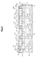
- Fig. 3 shows a state in which five cam caps 152 are removed from the cam carrier 150.
- the cam carrier 150 includes a front wall 154, a rear wall 156, and two side walls 158 and 160.
- four parallel bearings 162 extends so as to connect the side walls 158 and 160.
- the walls 154 to 160 and the bearing 162 are formed integrally.
- the front wall 154 also functions as a bearing.
- the cam carrier 150 is formed from the same aluminum alloy material as the cylinder block 4 and the cylinder head 8.
- the bearings 162 and the front wall 154 support the intake camshaft 45 and the exhaust camshaft 46 in a manner that they are parallel to each other and rotatable.
- the four variable valve lift mechanisms 120 which are respectively arranged in correspondence with the cylinders 2a, three intermediate collars 164, and two end collars 166, are arranged between the intake camshaft 45 and the side wall 158.
- the three intermediate collars 164 are arranged between the four variable valve lift mechanisms 120.
- the two end collars 166 are arranged at the outer sides of the two outer variable valve lift mechanisms 120.
- a rocker shaft 130 which commonly extends through the four variable valve lift mechanisms 120, supports the collars 164 and 166.
- each intermediate collar 164 includes a cylindrical sleeve 164a and two flanges 164b formed on the two ends of the sleeve 164a.
- the intermediate collar 164 has an interior space 164d (center bore).
- a pin hole 164c formed in the sleeve 164a is connected to the interior space 164d.
- each end collar 166 includes a cylindrical sleeve 166a and a flange 166b formed on one end of the sleeve 166a.
- the end collar 166 has an interior space 166d (center bore).
- a pin hole 166c formed in the sleeve 166a is connected to the interior space 166d.
- the collars 164 and 166 are each formed integrally from a steel material.
- variable valve lift mechanisms 120 will now be discussed with reference to Figs. 6 to 9.
- Each variable valve lift mechanism 120 includes an input sleeve 122 (input portion), a first rocking cam 124 (output portion) arranged rearward from the input sleeve 122, a second rocking cam 126 (output portion) arranged frontward from the input sleeve 122, and a slider gear 128 arranged in the input sleeve 122.
- the input sleeve 122 includes a housing 122a defining a cylindrical hollow space.
- a helical spline 122b (Fig. 9) is formed in the inner wall surface of the housing 122a.
- Each groove of the helical spline 122b extends helically about the axis of the housing 122a in the direction of a right-hand thread.
- Two parallel arms 122c and 122d extend from the outer walls surface of the housing 122a.
- a pin 122e extends between the distal ends of the arms 122c and 122d.
- the pin 122e extends parallel to the axis of the housing 122a. Further, the pin 122e rotatably supports a roller 122f. Referring to Fig.
- an urging member such as a spring
- the urging member may be arranged, for example, between the input sleeve 122 and the cylinder head 8 or rocker shaft 130.
- the first rocking cam 124 includes a housing 124a that defines a cylindrical internal space.
- a helical spline 124b (Fig. 9) is formed in the inner wall surface of the housing 124a.
- Each groove of the helical spline 124b extends helically about the axis of the housing 124a in the direction of a left-hand thread.
- the housing 124a includes a bearing end 124c having an end face in which a small center hole is formed.
- a triangular nose 124d extends from the outer wall surface of the housing 124a.
- the nose 124d includes a cam surface 124e curved in a concave manner.
- the second rocking cam 126 includes a housing 126a that defines a cylindrical internal space.
- a helical spline 126b (Fig. 9) is formed in the inner wall surface of the housing 126a.
- Each groove of the helical spline 126b extends helically about the axis of the housing 126a in the direction of a left-hand thread.
- the housing 126a includes a bearing end 126c having an end face in which a small center hole is formed.
- a triangular nose 126d extends from the outer wall surface of the housing 126a.
- the nose 126d includes a cam surface 126e curved in a concave manner.
- the first rockingcam 124, the input sleeve 122, and the second rocking cam 126 are coaxially aligned.
- the first rocking cam 124 and the second rocking cam 126 contact opposite ends of the input sleeve 122.
- the housings 122a, 124a, and 126a define a single internal space.
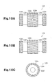
- Figs. 10 to 12 show the slider gear 128 retained in the housings 122a, 124a, and 126a.
- the slider gear 128 includes an input helical spline 128a, a first output helical spline 128c, and a second helical spline 128e.
- Each groove of the input helical spline 126b extends helically about the axis of the slider gear 128 in the direction of a right-hand thread.
- a small diameter portion 128b is formed between the input helical spline 128a and the first output helical spline 128c.
- a further small diameter portion 128d is formed between the input helical spline128a and the second output helical spline 128e.
- Each groove of the first output helical spline 128c and the second output helical spline 128e extend helically about the axis of the slider gear 128 in the direction of a left-hand thread.
- the diameter of the first output helical spline 128c and the diameter of the second output helical spline 128e are smaller than that of the input helical spline 128a.
- a gear bore 128f extends through the slider gear 128 along the slider gear axis.
- a circumferential groove 128g is formed in the inner wall surface of the gear bore 128f in the input helical spline 128a.
- a pin insertion hole 128h connects the circumferential groove 128g and the input helical spline 128a.
- Fig. 13A shows part of the rocker shaft 130.
- the gear bore 128f of the slider gear 128 rotatably receives the rocker shaft 130.
- the four variable valve lift mechanisms 120 are mounted on the single rocker shaft 130.
- the rocker shaft 130 is hollow and includes an interior space 130b.
- Four elongated holes 130a are formed in the outer surface of the rocker shaft 130 at positions corresponding to the variable valve lift mechanisms 120.
- Fig. 13B shows part of the control shaft 132.
- the control shaft 132 has a round cross-section.
- the control shaft 132 is received in the rocker shaft 130 and axially movable.
- the control shaft 132 includes support holes 132b respectively located at positions corresponding to the variable valve lift mechanisms 120. Each support hole 132b receives the basal portion of a control pin 132a. Each control pin 132a, which is supported by the corresponding support hole 132b, extends perpendicular to the axis of the control shaft 132.
- each control pin 132a projects from the corresponding elongated hole 130a of the rocker shaft 130. Referring to Fig. 14, the distal end of each control pin 132a is located in the circumferential groove 128g of the slider gear 128.
- the rocker shaft 130, the control shaft 132, and the control pin 132a are formed from a steel material and have high strength.
- a ball screw shaft 174 is formed on one end of the control shaft 132.
- the ball screw shaft 174 transmits the drive force of the slide actuator 100 to the control shaft 132.
- variable valve lift mechanisms 120 The assembly of the variable valve lift mechanisms 120, the rocker shaft 130, the control shaft 132, and the collars 164 and 166 will now be described.
- the control shaft 132 is first inserted through the rocker shaft 130.
- the variable valve lift mechanisms 120 and the collars 164 and 166 are alternately fastened to the rocker shaft 130.
- the control pins 132a are inserted in the pin insertion holes 128h of the corresponding slider gears 128 and the elongated holes 130a of the rocker shaft 130 and fastened to the control shaft 132 in the support holes 132b.
- fastening pins 168 are inserted through the pin holes 164c and 166c of the collars 164 and 166 and fastened to the rocker shaft 130 in pin holes 130c (Fig. 13). This fastens the collars 164 and 166 to the rocker shaft 130.
- the distal end of a bolt 170 for fastening the cam cap 152 located near the slide actuator 100 is inserted through the pin hole 166c of the corresponding collar 166 and into the pin hole 130c of the rocker shaft 130. Accordingly, the collar 166 located near the slide actuator 100 is fixed to the rocker shaft 130 by the bolt 170 when fastening the cam cap 152.
- the variable valve lift mechanisms 120, the rocker shaft 130, the control shaft 132, and the collars 164 and 166 are assembled as a single unit. In this state, the flanges 164b and 166b of the collars 164 and 166 are in contact with the end faces of the adjacent variable valve lift mechanisms 120.
- shim plates 172 which are formed from a steel material, are arranged between the variable valve lift mechanisms 120 and the collars 164 and 166 if necessary to adjust the position of each variable valve lift mechanism 120.
- the flanges 164b and 166b of the collars 164 and 166 indirectly contact the end faces of the adjacent variable valve lift mechanisms 120.
- the shaft assembly shown in Fig. 16 is formed from a steel material. Referring to Fig. 2, the shaft assembly is secured to the cam carrier 150 by five cam caps 152.
- the bolt 170 for fastening the cam cap 152 that is close to the slide actuator 100 restricts movement of the shaft assembly in the axial direction.
- the bolts for fastening the other three cam caps 152 do not restrict movement of the collars 164 and 166 in the axial direction.
- the lengths of the sleeves 164a and 166a of the collars 164 and 166 in the axial direction are greater than the thicknesses of the front wall 154, the bearings 162, and the cam caps 152.
- clearances CL are formed between the flanges 164b and 166b and the adjacent front wall 154 or bearing 162 and cam cap 152.
- the slide actuator 100 drives a ball screw mechanism 210 (Figs. 2 and 3) to move the control shaft 132, which includes the ball screw shaft 174, in the axial movement.
- the movement adjusts the axial position of the slider gear 128 in each variable valve lift mechanism 120.
- the control pin 132a is received in the circumferential groove 128g of the slider gear 128.
- the slider gear 128 is rotatable relative to the control shaft 132 regardless of the position of the control pin 132a.
- the input helical spline 128a of the slider gear 128 meshes with the helical spline 122b of the input sleeve 122.
- the first output helical spline 128c meshes with the helical spline 124b of the first rocking cam 124.
- the second output helical spline 128e meshes with the helical spline 126b of the second rocking cam 126.
- the input splines 122b and 128a differ from the splines 124b, 128c, 126b, and 128e in the helical direction (helical angle) relative to the control shaft 132.
- each variable valve lift mechanism 120 the collars 164 and 166 are arranged on opposite sides of each variable valve lift mechanism 120. This restricts axial movement of the input sleeve 122 and the rocking cams 124 and 126 in each variable valve lift mechanism 120 relative to the rocker shaft 130. Thus, even if the control shaft 132 axially moves the slider gears 128; axial movement of the input sleeves 122 and the rocking cams 124 and 126 is restricted.
- the slider gear 128 When the slide actuator 100 axially moves the control shaft 132, the slider gear 128 axially moves in the internal space of the corresponding variable valve lift mechanism 120.
- the helical splines 128a, 122b, 128c, 124b, 128e, and 126b function to relatively rotate the input sleeve 122 and the rocking cams 124 and 126.
- the input sleeve 122 rotates in a direction opposite to that of the rocking cams 124 and 126.
- the rotation angle of the input sleeve 122 and the rocking cams 124 and 126 are determined in accordance with the movement of the slider gear 128.
- adjustment of the movement amount of the control shaft 132 changes the positions (angle along the circumferential direction of the rocker shaft 130) of the rollers 122f relative to the noses 124d and 126d. This adjusts the lift amount of the intake valves 12.
- Fig. 18A shows the intake valve 12 when it is closed and Fig. 18B shows.the intake valve 12 when it is open in a state in which the control shaft 132 is moved by the maximum amount in direction L (Fig. 16).
- the angle between the roller 122f and the nose 126d (124d) in each variable valve lift mechanism 120 is minimal.
- the amount the cam surfaces 124e and 126e of the noses 124d and 126d push the rocker roller 52a down, that is, the maximum lift amount of the intake valve 12 is relatively small. In this case, the amount of air supplied to each combustion chamber 10 from the corresponding intake port 14 is minimal.
- Fig. 19A shows the intake valve 12 when it is closed and Fig. 19B shows the intake valve 12 when it is open in a state in which the control shaft 132 is moved by the maximum amount in direction H (Fig. 16).
- H the maximum amount in direction H
- the angle between the roller 122f and the nose 126d (124d) in each variable valve lift mechanism 120 is maximal.
- the amount the cam surfaces 124e and 126e of the noses 124d and 126d push the rocker roller 52a down, that is, the minimum lift amount of the intake valve 12 is relatively large. In this case, the amount of air supplied to each combustion chamber 10 from the corresponding intake port 14 is maximal.
- the control shaft 132 axially moves between the state of Fig. 18 and the state of Fig. 19 in a continuous (stepless) manner. Adjustment of the movement amount of the control shaft 132 adjusts the lift amount of each intake valve 12 in a continuous (stepless) manner. Accordingly, the intake air amount is adjustable in a stepless manner without using a throttle valve.
- the intake port 14 when the lift amount of the intake valve 12 is minimal, the intake port 14 is slightly open. However, the intake port 14 may be closed when the lift amount of the intake valve 12 is minimal. This is a state in which the minimal lift amount of the intake valve 12 is zero and the intake air amount is zero.
- the rocker shaft 130 functions as a shaft (hollow shaft).
- the front wall 154 and the bearings 162 of the cam carrier 150 function as supports.
- the flanges 164b and 166b formed on the ends of the sleeves 164a and 166a function to position the variable valve lift mechanisms 120.
- the shaft assembly (Fig. 16) including the variable valve lift mechanisms 120, the ball screw mechanism 210, and the slide actuator 100 form a variable valve actuation mechanism.
- the first embodiment has the advantages described below.
- This contact determines the distance (positional relationship) between the variable valve lift mechanisms 120 in the axial direction.
- the flanges 164b and 166b are spaced from the front wall 154, the bearings 162, and the cam caps 152 by clearance C. Accordingly, changes in the interval of the supports (front wall 154 and bearings 162) in the cam carrier 150 does not affect the positional relationship between the variable valve lift mechanisms 120. Even if a difference in coefficient of thermal expansion exists between the cam carrier 150 and the control shaft 132, the coefficient of thermal expansion of the cam carrier 150 does not affect the positional relationship of the variable valve lift mechanisms 120.
- the coefficient of thermal expansion of the collars 164 and 166, the input sleeves 122, and the rocking cams 124 and 126 affect the positional relationship of the variable valve lift mechanisms 120.
- the collars 164 and 166, the input sleeves 122, and the rocking cams 124 and 126 are formed from a steel material having a coefficient of thermal expansion that is the same or approximate to that of the material the control shaft 132 is formed from.
- the intake valves 12 have substantially the same lift amount in all of the cylinders. Since temperature changes do not cause differences between cylinders in the lift amount of the intake valves 12, the accuracy of lift amount adjustment is improved.
- a variable valve actuation mechanism is similar to that of the first embodiment except in that the rocker shaft 130 is omitted.
- a plurality of collars 364 (Fig. 21) are used in lieu of the collars 164 and 166 of the first embodiment. Referring to Fig. 20, the collars 364 function as pivot shafts of variable valve lift mechanisms 320.
- the cylinder block, the cylinder head, and the cam carrier 350 are formed from a steel material.
- each collar 364 includes a cylindrical sleeve 364a, two flanges formed on the two ends of the sleeve 364a, and a shaft projection or pivot shaft portion 364c extending from each flange 364b along the axis of the sleeve 364a.
- the collar 364 has a center bore 364d. Further, the collar 364 is formed from a steel material.
- a control shaft 332 extends through the center bores 364d of the collars 364.
- the control shaft 332 directly supports the collars 364.
- the pivot shaft portions 364c of each collar 364 are received by bearing ends 324c and 326c of the adjacent variable valve lift mechanism 320. This rotably supports the rocking cams 324 and 326 of each variable valve lift mechanism 320 with the pivot shaft portions 364c of the two adjacent collars 364.
- a control pin 332a which is fixed to the control shaft 332, is engaged with a slider gear 328. Movement of the control shaft 332 moves the slider gear 328 in the axial direction. The omission of a rocker shaft that would extend through the entire variable valve lift mechanism 320 reduces the diameter of each variable valve lift mechanism 320.
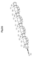
- shim plates 372 are arranged between the collars 364 and the rocking cams 324 and 326.
- the shaft assembly is mounted on _the cam carrier 350.
- the distance between the two flanges 364b in each collar 364 is substantially the same as the thicknesses of a front wall 354 and the bearings 362.
- the front wall 354 and the bearings 362 support the collars 364 in a rotatable manner.
- the front wall 354 and the bearings 362 are held between the two flanges 364b of the corresponding collars 364. This prevents each collar 364 from being moved in the axial direction and determines the position of each variable valve lift mechanism 320 (input shaft 322, and rocking cams 324 and 326) in the axial direction.
- control shaft 332 functions as a shaft.
- the pivot shaft portions 364c formed on the ends of the sleeves 364a function to position the variable valve lift mechanisms 320.
- the second embodiment has the advantages described below.
- the pivot shaft portions 364c are formed on opposite ends of each collar 364.
- the pivot shaft portions 354c pivotally support the adjacent variable valve lift mechanism 320 and function as a pivot shaft of the variable valve lift mechanisms 320. This eliminates the need for a rocker shaft that extends through the variable valve lift mechanisms 320 and reduces the diameter of the variable valve lift mechanisms 320.
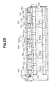
- FIG. 26 shows a cam carrier 550 from which cam caps are removed.
- the third embodiment employs collars 564 that are similar to those of the second embodiment. However, the distance between two flanges 564b in each collar 564 is greater than the thicknesses of a front wall 554 and bearings 562 of the cam carrier 550. This enables movement of the collars 564 in the axial direction with respect to the front wall 554 and the bearings 562.
- Each variable valve lift mechanism 520 is rotatably supported by pivot shaft portions 564c of the adjacent collar 564 without the use of a rocker shaft.
- the collar 564 located farthest from the slide actuator 500 is fixed to the front wall 554 by a pin 565 and does not move in the axial direction.
- the collar 564 located closest to the slide actuator 500 is pushed toward the corresponding variable valve lift mechanism 520 by a spring 567. This keeps the collars 564 in a state directly contacting the variable valve lift mechanisms 520 or in a state indirectly contacting the variable valve lift mechanisms 520 by means of shim plates 572.
- the cylinder block, the cylinder head, and the cam carrier 550 are formed from an aluminum alloy material.
- the variable valve lift mechanisms 520, the collars 564, and the shim plates 572 are formed from a steel material.
- the control shaft 532 functions as a shaft.
- the flanges 564b and pivot shaft portions 564c formed on the ends of the sleeves 564a function to position the variable valve lift mechanisms 520.
- the third embodiment has the advantages described below.
- the flanges 564b of the collars 564 directly contact the end faces of the rocking cams 524 and 526 or indirectly contacts the end faces of the rocking cams 524 and 526 by means of the shim plates 572. This contact determines the positions of the variable valve lift mechanisms 520 in the axial direction.
- the flanges 564b are spaced with a clearance from the adjacent bearings 562 and cam caps. The positional relationship of the variable valve lift mechanisms 520 is affected only by the coefficient of thermal expansion of the collars 564, the input sleeves 522, and the rocking cams 524 and 526.
- the collars 564, the input sleeves 522, and the rocking cams 524 and 526 are formed from a steel material having a coefficient of thermal expansion that is the same or approximate to that of the material the control shaft 532 is formed from. Accordingly, even if temperature changes affect the collars 564, the input sleeves 522, and the rocking cams 524 and 526, the change in the positions of the slider gears in the variable valve lift mechanisms 520, which is determined by the control shaft 532, is substantially the same as the change in the positions of the input sleeve 522 and the rocking cams 524 and 526. Thus, the intake valves 12 have substantially the same lift amount in all of the cylinders. Since temperature changes do not cause differences between cylinders in the lift amount of the intake valves 12, the accuracy of lift amount adjustment is improved.
- the pivot shaft portions 564c are-formed on the two ends of each collar 564.
- the pivot shaft portions 564c rotatably support the adjacent variable valve lift mechanisms 520. Since the pivot shaft portions 564c function as pivot shafts of the variable valve lift mechanisms 520, the diameter of the variable valve lift mechanisms 520 is reduced.
- variable valve lift mechanisms and the camshafts may be directly mounted on the cylinder head without using a cam carrier.
- the engine is not limited to a gasoline engine and may be any type of engine such as a diesel engine. Further, the engine is not limited to an engine used to drive vehicles and may be an engine used for other applications. In addition to lift amount adjustment of intake valves, the present invention may be applied to lift amount adjustment of exhaust valves or lift amount adjustment of both intake and exhaust valves.
- the collars restrict movement of the variable valve lift mechanisms in the axial direction.
- positioning members such as pins may be arranged on the rocker shaft. The positioning members may restrict movement of the variable valve lift mechanisms in the axial direction. This fixes the positional relationship of the variable valve lift mechanisms with respect to the rocker shaft. Thus, the distance between the bearings arranged on the cam carrier or cylinder head does not affect the positional relationship between the variable valve lift mechanisms.
- a variable valve actuation mechanism may be formed from a material selected in accordance with the strength requirements. Further, even if a temperature change occurs, the valve lift adjustment amount is prevented from differing between cylinders. This improves the accuracy for adjusting the valve lift amount.
Landscapes
- Engineering & Computer Science (AREA)
- Mechanical Engineering (AREA)
- General Engineering & Computer Science (AREA)
- Valve Device For Special Equipments (AREA)
- Valve-Gear Or Valve Arrangements (AREA)
Abstract
Description
- The present invention relates to a collar for receiving a shaft for a variable valve lift mechanism in a multiple-cylinder internal combustion engine.
- Japanese Laid-Open Patent Publication No. 2001-263015 describes a variable valve actuation mechanism for an internal combustion engine. The variable valve actuation mechanism includes a variable valve lift mechanism, which is arranged for each cylinder to adjust the lift amount of intake and exhaust valves. A support pipe (rocker shaft) extends through the center of the variable valve lift mechanism. A control shaft is arranged in the support pipe. The variable valve lift mechanism is pivoted in a state supported by the support pipe. The lift amount of the valve is adjusted by moving the control shaft in the axial direction.
- The support pipes are supported by a plurality of supports arranged on a cylinder head between the variable valve lift mechanisms. The supports position the variable valve lift mechanisms in the axial direction. The valve lift mechanisms are positioned in the axial direction with high accuracy so that the movement of the control shaft adjusts the valve lift amount to be the same in every cylinder.
- In an internal combustion engine, the cylinder block, cylinder head, and cam carrier are formed from a light alloy or a light metal, such as aluminum, to reduce weight. However, shafts included in the variable valve actuation mechanism, such as the control shaft, are not formed from a light alloy or a light metal and formed from a steel material, such as cast steel or cast iron, to meet the high strength requirements.
- The coefficient of thermal expansion differs greatly between light alloy and steel. Thus, when comparing a state in which the engine is cool and a state in which the engine is warm, the control shaft becomes shorter and changes the interval between the supports located closer to the cylinder head and cam carrier. This produces a difference in the relative positions of the control shaft and the variable valve lift mechanism between cylinders close to the basal end of the control shaft and cylinders close to the distal end of the control shaft. Accordingly, the lift amount differs between cylinders. Such difference causes difficulties for adjusting the combustion state of each cylinder with high accuracy. This may generate vibrations or deteriorate emission and cause an undesirable engine operation state.
- The rocker shaft, which supports the variable valve lift mechanism, is arranged at the outer side of the control shaft. When the rocker shaft, which receives the control shaft, has a large diameter, the variable valve lift mechanism that receives the rocker shaft is enlarged. This enlarges and increases the weight of the variable valve actuation mechanism, which would contradict the demand for a smaller and lighter internal combustion engine.
- It is an object of the present invention to provide a variable valve actuation mechanism that substantially equally adjusts the valve lift amount in each cylinder. Another object of the present invention is to provide a compact and light variable valve actuation mechanism. A further aspect of the present invention is to provide a collar for such a variable valve actuation mechanism.
- One aspect of the present invention is a collar for receiving a shaft of a multiple cylinder engine. The shaft supports a plurality of variable valve lift mechanisms respectively arranged in correspondence with a plurality of cylinders. Each variable valve lift mechanism has an end face, and the engine includes a plurality of supports for supporting the shaft. The collar includes a sleeve extending in an axial direction and end portions formed integrally with the sleeve. In use, a plurality of said collars are fastened to the shaft, with the sleeve of each collar being arranged between the shaft and a corresponding one of the supports so that at least one of the end portions directly or indirectly contacts or engages the end face of one of the variable valve lift mechanisms to determine the positions of the variable valve lift mechanisms.
- Another aspect of the present invention is a variable valve actuation mechanism for use in a multiple cylinder engine. The variable valve actuation mechanism includes a plurality of variable valve lift mechanisms respectively arranged in association with the cylinders of the engine. Each variable valve lift mechanism includes an end face. A control shaft extends through the variable valve lift mechanisms in an axial direction. An actuator moves the control shaft in the axial direction and drives the variable valve lift mechanisms. A plurality of collars are arranged alternately with the variable valve lift mechanisms for determining the positions of the variable valve lift mechanisms with respect to one another in the axial direction. Each collar includes a sleeve extending in the axial direction and end portions formed integrally with the sleeve. At least one of the end portions directly or indirectly contacts the end face of one of the variable valve lift mechanisms.
- A further aspect of the present invention is a variable valve actuation mechanism for use in a multiple cylinder engine. The variable valve actuation mechanism includes a plurality of variable valve lift mechanisms respectively arranged in association with the cylinders of the engine. Each variable valve lift mechanism includes an end face. A control shaft extends through the variable valve lift mechanisms in an axial direction. An actuator moves the control shaft in the axial direction and drives the variable valve lift mechanisms. A plurality of collars are arranged alternately with the variable valve lift mechanisms for determining the positions of the variable valve lift mechanisms with respect to one another in the axial direction. Each collar includes a sleeve extending in the axial direction and end portions formed integrally with the sleeve. At least one of the end portions engages the end face of an adjacent one of the variable valve lift mechanisms and includes a shaft projection functioning as part of a pivot shaft of the variable valve lift mechanisms.
- Another aspect of the present invention is a variable valve actuation mechanism for use in a multiple cylinder engine. The variable valve actuation mechanism includes a plurality of variable valve lift mechanisms respectively arranged in association with the cylinders of the engine. Each variable valve lift mechanism includes an end face. A control shaft extends through the variable valve lift mechanisms in an axial direction. An actuator moves the control shaft in the axial direction and drives the variable valve lift mechanisms. A plurality of collars are arranged alternately with the variable valve lift mechanisms for determining the positions of the variable valve lift mechanisms with respect to one another in the axial direction. Each collar includes a sleeve extending in the axial direction and end portions formed integrally with the sleeve. At least one of the end portions directly or indirectly contacts the end face of an adjacent one of the variable valve lift mechanisms to determine the positional relationship between the variable valve lift mechanisms in the axial direction, and includes a shaft projection for engaging the end face of the one of the variable valve lift mechanisms to function as part of a pivot shaft of the variable valve lift mechanism.
- A further aspect of the present invention is a variable valve actuation mechanism for use in a multiple cylinder engine. The variable valve actuation mechanism includes a plurality of variable valve lift mechanisms respectively arranged in association with the cylinders of the engine. Each variable valve lift mechanism has an end face. A control shaft extends through the variable valve lift mechanisms in an axial direction. A hollow shaft receives the control shaft. The hollow shaft is formed from a metal material having a first coefficient of thermal expansion. An actuator moves the control shaft in the axial direction and drives the variable valve lift mechanisms. A plurality of collars are fastened to the hollow shaft and arranged alternately with the variable valve lift mechanisms for determining the positions of the variable valve lift mechanisms with respect to one another in the axial direction. A plurality of supports respectively support the collars. Each collar includes a sleeve extending in the axial direction and end portions formed integrally with the sleeve. The sleeve and the at least one end portion is formed from a material having a coefficient of thermal expansion that is equal to or approximate to the first coefficient of thermal expansion. Each collar is supported by the corresponding support such that a clearance is formed between the end face of an adjacent one of the variable valve lift mechanisms and the corresponding support. The contact shaft and the support holding the collar such as to restrict the sleeve from becoming eccentric while enabling movement of the collar in the axial direction.
- Another aspect of the present invention is a variable valve actuation mechanism for use in a multiple cylinder engine. The variable valve actuation mechanism includes a plurality of variable valve lift mechanisms respectively arranged in association with the cylinders of the engine. Each variable valve lift mechanism has an end face. A control shaft extends in an axial direction. The variable valve lift mechanisms are fastened to a hollow shaft, which receives the control shaft. An actuator moves the control shaft in the axial direction and drives the variable valve lift mechanisms. A plurality of supports support the variable valve lift mechanisms via the hollow shaft. The variable valve lift mechanisms are fastened to the hollow shaft in a state in which movement in the axial direction is restricted in order to determine the positions of the variable valve lift mechanisms with respect to one another in the axial direction.
- Other aspects and advantages of the present invention will become apparent from the following description, taken in conjunction with the accompanying drawings, illustrating by way of example the principles of the invention.
- The invention, together with objects and advantages thereof, may best be understood by reference to the following description of the presently preferred embodiments together with the accompanying drawings in which:
- Fig. 1 is a cross-sectional diagram showing an engine and a variable valve actuation mechanism according to a first embodiment of the present invention;
- Fig. 2 is a plan view showing the engine of Fig. 1;
- Fig. 3 is a plan view showing a cam carrier of the first embodiment;
- Figs. 4A, 4B, and 4C are respectively plan, front, and perspective views showing an intermediate collar of the first embodiment;
- Figs. 5A, 5B, and 5C are respectively plan, front, and perspective views showing an end collar of the first embodiment;
- Fig. 6 is a perspective view showing a variable valve lift mechanism of the first embodiment;
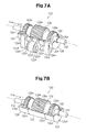
- Figs. 7A and 7B are partially cutaway perspective views showing the variable valve lift mechanism of the first embodiment;
- Fig. 8 is an exploded perspective view showing the variable valve lift mechanism of Fig. 6;
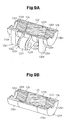
- Figs. 9A and 9B are partially cutaway perspective views showing the variable valve lift mechanism of Fig. 6;
- Figs. 10A, 10B, and 10C are plan views and a front view showing a slider gear of the first embodiment;
- Fig. 11 is a perspective view showing the slider gear of Figs. 10A, 10B, and 10C;
- Fig. 12 is a partial cutaway perspective view showing the slider gear of Fig. 11;
- Fig. 13A is a perspective view showing a rocker shaft of the first embodiment;
- Fig. 13B is a perspective view showing a control shaft of the first embodiment;
- Fig. 13C is a perspective view showing the rocker shaft retained in the control shaft of Fig. 13B;
- Fig. 14 is a partial cutaway perspective view showing the variable valve lift mechanism of Fig. 6;
- Fig. 15 is a perspective view showing a plurality of collars arranged between variable valve lift mechanisms;
- Fig. 16 is a perspective view showing the collars fastened to the control shaft and the variable valve lift mechanisms;
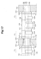
- Fig. 17 is a diagram showing clearances formed between the collars and the cam carriers;
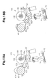
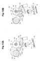
- Figs. 18A, 18B, 19A, and 19B show the operation of the variable valve lift mechanism of Fig. 6;
- Fig. 20 is a plan view showing a cam carrier according to a second embodiment of the present invention;
- Figs. 21A, 21B, and 21C are respectively front, side, and perspective views showing a collar of the second embodiment;
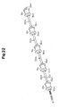
- Fig. 22 is a perspective view showing a plurality of collars fastened to a control shaft;
- Figs. 23 and 24 are enlarged cross-sectional diagrams showing the joint between a collar and variable valve lift mechanism;
- Fig. 25 is a perspective view showing the collars fastened to the control shaft and the variable valve lift mechanisms; and
- Fig. 26 is a plan view showing a cam carrier according to a third embodiment of the present invention.
-
- Fig. 1 is a schematic cross-sectional diagram showing a cylinder of a multiple-
cylinder gasoline engine 2, which is installed in a vehicle. Fig. 2 is a plan view showing acam carrier 150 arranged on the upper portion of theengine 2. - The
engine 2 includes acylinder block 4,pistons 6, and a cylinder head 8 mounted on thecylinder block 4. Thecylinder block 4 and the cylinder head 8 are formed from an aluminum alloy material. - A plurality of (four)
cylinders 2a are defined in thecylinder block 4. Acombustion chamber 10 is defined in eachcylinder 2a between thecylinder block 4, thecorresponding piston 6, and the cylinder head 8. Twointake valves 12 and twoexhaust valves 16 are arranged in eachcylinder 2a. Theintake valves 12 and theexhaust valves 16 respectively open and close associatedintake ports 14 andexhaust ports 18. - Each
intake port 14 is connected to a surge tank via an intake passage formed in an intake manifold. Eachcylinder 2a is supplied with air from the surge tank. A fuel injector is arranged in each intake passage to inject fuel into theintake port 14 of thecorresponding cylinder 2a. In this manner, fuel is supplied to a position upstream from theintake valve 12. Fuel may be directly supplied into eachcombustion chamber 10 as in an in-cylinder injection type gasoline engine. - The lift amount of the
intake valve 12 is varied to adjust the intake air amount. Theengine 2 of the first embodiment does not include a throttle valve that would be arranged in an intake passage upstream from the surge tank in a normal engine. However, theengine 2 of the first embodiment may include an auxiliary throttle valve. When an auxiliary throttle valve is employed, the auxiliary throttle valve is, for example, fully opened when theengine 2 is started and fully closed when theengine 2 is stopped. The open amount of the auxiliary throttle valve may be adjusted to control the intake air amount when lift amount adjustment of theintake valves 12 withvalve lift mechanisms 120 is disabled. - Referring to Fig. 1, rotation of an
intake camshaft 45 rotates anintake cam 45a. A variablevalve lift mechanism 120 arranged on the cylinder head 8 converts the rotation of theintake cam 45a to a pivoting action of aroller rocker arm 52. Movement of theroller rocker arm 52 drives theintake valve 12. In this manner, the drive force of theintake camshaft 45 is transmitted to theintake valve 12. - Referring to Fig. 2, a
slide actuator 100 adjusts the transmission state of the variablevalve lift mechanisms 120 to adjust the lift amount of theintake valves 12. - A variable
valve timing mechanism 140 is arranged at the front end of theintake camshaft 45. Theintake camshaft 45 rotates in cooperation with the rotation of acrankshaft 49 of theengine 2 by means of a timing sprocket of the variablevalve timing mechanism 140 and atiming chain 47. - An
exhaust camshaft 46 is rotated in cooperation with rotation produced by theengine 2.Exhaust cams 46a arranged on theexhaust camshaft 46 open and closecorresponding exhaust valves 16 with a constant lift amount by means ofroller rocker arms 54. Eachexhaust port 18 is connected to an exhaust manifold. Exhaust passes through a purification catalyst converter before being discharged. - The
intake camshaft 45, theexhaust camshaft 46, theslide actuator 100, the variablevalve lift mechanisms 120, and the variablevalve timing mechanism 140 are incorporated as a single unit in thecam carrier 150. Fig. 3 shows a state in which fivecam caps 152 are removed from thecam carrier 150. - The
cam carrier 150 includes afront wall 154, arear wall 156, and twoside walls walls parallel bearings 162 extends so as to connect theside walls walls 154 to 160 and thebearing 162 are formed integrally. Thefront wall 154 also functions as a bearing. Thecam carrier 150 is formed from the same aluminum alloy material as thecylinder block 4 and the cylinder head 8. - The
bearings 162 and thefront wall 154 support theintake camshaft 45 and theexhaust camshaft 46 in a manner that they are parallel to each other and rotatable. The four variablevalve lift mechanisms 120, which are respectively arranged in correspondence with thecylinders 2a, threeintermediate collars 164, and twoend collars 166, are arranged between theintake camshaft 45 and theside wall 158. The threeintermediate collars 164 are arranged between the four variablevalve lift mechanisms 120. The twoend collars 166 are arranged at the outer sides of the two outer variablevalve lift mechanisms 120. Arocker shaft 130, which commonly extends through the four variablevalve lift mechanisms 120, supports thecollars - Referring to Figs. 4A, 4B, and 4C, each
intermediate collar 164 includes acylindrical sleeve 164a and twoflanges 164b formed on the two ends of thesleeve 164a. Theintermediate collar 164 has aninterior space 164d (center bore). Apin hole 164c formed in thesleeve 164a is connected to theinterior space 164d. - Referring to Figs. 5A, 5B, and 5C, each
end collar 166 includes acylindrical sleeve 166a and aflange 166b formed on one end of thesleeve 166a. Theend collar 166 has aninterior space 166d (center bore). Apin hole 166c formed in thesleeve 166a is connected to theinterior space 166d. Thecollars - The variable
valve lift mechanisms 120 will now be discussed with reference to Figs. 6 to 9. - Each variable
valve lift mechanism 120 includes an input sleeve 122 (input portion), a first rocking cam 124 (output portion) arranged rearward from theinput sleeve 122, a second rocking cam 126 (output portion) arranged frontward from theinput sleeve 122, and aslider gear 128 arranged in theinput sleeve 122. - The
input sleeve 122 includes ahousing 122a defining a cylindrical hollow space. Ahelical spline 122b (Fig. 9) is formed in the inner wall surface of thehousing 122a. Each groove of thehelical spline 122b extends helically about the axis of thehousing 122a in the direction of a right-hand thread. Twoparallel arms housing 122a. Apin 122e extends between the distal ends of thearms pin 122e extends parallel to the axis of thehousing 122a. Further, thepin 122e rotatably supports aroller 122f. Referring to Fig. 1, the force of an urging member, such as a spring, constantly pushes theroller 122f towards theintake cam 45a. The urging member may be arranged, for example, between theinput sleeve 122 and the cylinder head 8 orrocker shaft 130. - The
first rocking cam 124 includes ahousing 124a that defines a cylindrical internal space. Ahelical spline 124b (Fig. 9) is formed in the inner wall surface of thehousing 124a. Each groove of thehelical spline 124b extends helically about the axis of thehousing 124a in the direction of a left-hand thread. Thehousing 124a includes abearing end 124c having an end face in which a small center hole is formed. Atriangular nose 124d extends from the outer wall surface of thehousing 124a. Thenose 124d includes acam surface 124e curved in a concave manner. - The
second rocking cam 126 includes ahousing 126a that defines a cylindrical internal space. Ahelical spline 126b (Fig. 9) is formed in the inner wall surface of thehousing 126a. Each groove of thehelical spline 126b extends helically about the axis of thehousing 126a in the direction of a left-hand thread. Thehousing 126a includes abearing end 126c having an end face in which a small center hole is formed. Atriangular nose 126d extends from the outer wall surface of thehousing 126a. Thenose 126d includes acam surface 126e curved in a concave manner. - Referring to Fig. 8, the
first rockingcam 124, theinput sleeve 122, and thesecond rocking cam 126 are coaxially aligned. Thefirst rocking cam 124 and thesecond rocking cam 126 contact opposite ends of theinput sleeve 122. Thehousings - Figs. 10 to 12 show the
slider gear 128 retained in thehousings slider gear 128 includes an inputhelical spline 128a, a first outputhelical spline 128c, and a secondhelical spline 128e. Each groove of the inputhelical spline 126b extends helically about the axis of theslider gear 128 in the direction of a right-hand thread. Asmall diameter portion 128b is formed between the inputhelical spline 128a and the first outputhelical spline 128c. A furthersmall diameter portion 128d is formed between the input helical spline128a and the secondoutput helical spline 128e. Each groove of the first outputhelical spline 128c and the secondoutput helical spline 128e extend helically about the axis of theslider gear 128 in the direction of a left-hand thread. The diameter of the first outputhelical spline 128c and the diameter of the secondoutput helical spline 128e are smaller than that of the inputhelical spline 128a. - Referring to Fig. 12, a
gear bore 128f extends through theslider gear 128 along the slider gear axis. Acircumferential groove 128g is formed in the inner wall surface of the gear bore 128f in the inputhelical spline 128a. Apin insertion hole 128h connects thecircumferential groove 128g and the inputhelical spline 128a. - Fig. 13A shows part of the
rocker shaft 130. The gear bore 128f of theslider gear 128 rotatably receives therocker shaft 130. As shown in Fig. 3, the four variablevalve lift mechanisms 120 are mounted on thesingle rocker shaft 130. - The
rocker shaft 130 is hollow and includes aninterior space 130b. Fourelongated holes 130a are formed in the outer surface of therocker shaft 130 at positions corresponding to the variablevalve lift mechanisms 120. - Fig. 13B shows part of the
control shaft 132. Thecontrol shaft 132 has a round cross-section. Referring to Fig. 13C, thecontrol shaft 132 is received in therocker shaft 130 and axially movable. - The
control shaft 132 includes support holes 132b respectively located at positions corresponding to the variablevalve lift mechanisms 120. Eachsupport hole 132b receives the basal portion of acontrol pin 132a. Eachcontrol pin 132a, which is supported by the correspondingsupport hole 132b, extends perpendicular to the axis of thecontrol shaft 132. - When the
control shaft 132 is received in therocker shaft 130, eachcontrol pin 132a projects from the correspondingelongated hole 130a of therocker shaft 130. Referring to Fig. 14, the distal end of eachcontrol pin 132a is located in thecircumferential groove 128g of theslider gear 128. - The
rocker shaft 130, thecontrol shaft 132, and thecontrol pin 132a are formed from a steel material and have high strength. - Referring to Fig. 16, a
ball screw shaft 174 is formed on one end of thecontrol shaft 132. Theball screw shaft 174 transmits the drive force of theslide actuator 100 to thecontrol shaft 132. - The assembly of the variable
valve lift mechanisms 120, therocker shaft 130, thecontrol shaft 132, and thecollars - The
control shaft 132 is first inserted through therocker shaft 130. Referring to Fig. 15, the variablevalve lift mechanisms 120 and thecollars rocker shaft 130. Referring to Fig. 8, thecontrol pins 132a are inserted in thepin insertion holes 128h of the corresponding slider gears 128 and theelongated holes 130a of therocker shaft 130 and fastened to thecontrol shaft 132 in the support holes 132b. Referring to Fig. 15, fastening pins 168 are inserted through the pin holes 164c and 166c of thecollars rocker shaft 130 inpin holes 130c (Fig. 13). This fastens thecollars rocker shaft 130. - Among the five
cam caps 152, the distal end of abolt 170 for fastening thecam cap 152 located near theslide actuator 100 is inserted through thepin hole 166c of thecorresponding collar 166 and into thepin hole 130c of therocker shaft 130. Accordingly, thecollar 166 located near theslide actuator 100 is fixed to therocker shaft 130 by thebolt 170 when fastening thecam cap 152. In this manner, as shown in the state of Fig. 16, the variablevalve lift mechanisms 120, therocker shaft 130, thecontrol shaft 132, and thecollars flanges collars valve lift mechanisms 120. - During the assembly,
shim plates 172, which are formed from a steel material, are arranged between the variablevalve lift mechanisms 120 and thecollars valve lift mechanism 120. In this case, theflanges collars valve lift mechanisms 120. - The shaft assembly shown in Fig. 16 is formed from a steel material. Referring to Fig. 2, the shaft assembly is secured to the
cam carrier 150 by five cam caps 152. Thebolt 170 for fastening thecam cap 152 that is close to theslide actuator 100 restricts movement of the shaft assembly in the axial direction. The bolts for fastening the other threecam caps 152 do not restrict movement of thecollars - As shown in Figs. 2 and 3, the lengths of the
sleeves collars front wall 154, thebearings 162, and the cam caps 152. Referring to Fig. 17, clearances CL are formed between theflanges front wall 154 or bearing 162 andcam cap 152. Even if there is a difference in the expansion and contraction amount of thecontrol shaft 132 and thecam carrier 150 due to a difference in the coefficient of thermal expansion, thecollars collar 166 fastened by thebolt 170, move in the axial direction of thecontrol shaft 132 and absorb the difference in the expansion and contraction amounts. Accordingly, the axial positions of the variablevalve lift mechanisms 120 do not change, and the relative positions of thecontrol shaft 132 and the variablevalve lift mechanisms 120 in the axial direction do not change. - The
slide actuator 100 drives a ball screw mechanism 210 (Figs. 2 and 3) to move thecontrol shaft 132, which includes theball screw shaft 174, in the axial movement. The movement adjusts the axial position of theslider gear 128 in each variablevalve lift mechanism 120. - Referring to Fig. 14, the
control pin 132a is received in thecircumferential groove 128g of theslider gear 128. Thus, theslider gear 128 is rotatable relative to thecontrol shaft 132 regardless of the position of thecontrol pin 132a. - The input
helical spline 128a of theslider gear 128 meshes with thehelical spline 122b of theinput sleeve 122. The first outputhelical spline 128c meshes with thehelical spline 124b of thefirst rocking cam 124. The secondoutput helical spline 128e meshes with thehelical spline 126b of thesecond rocking cam 126. The input splines 122b and 128a differ from thesplines control shaft 132. - Referring to Fig. 16, the
collars valve lift mechanism 120. This restricts axial movement of theinput sleeve 122 and the rockingcams valve lift mechanism 120 relative to therocker shaft 130. Thus, even if thecontrol shaft 132 axially moves the slider gears 128; axial movement of theinput sleeves 122 and the rockingcams - When the
slide actuator 100 axially moves thecontrol shaft 132, theslider gear 128 axially moves in the internal space of the corresponding variablevalve lift mechanism 120. Thehelical splines input sleeve 122 and the rockingcams input sleeve 122 rotates in a direction opposite to that of the rockingcams input sleeve 122 and the rockingcams slider gear 128. Accordingly, adjustment of the movement amount of thecontrol shaft 132 changes the positions (angle along the circumferential direction of the rocker shaft 130) of therollers 122f relative to thenoses intake valves 12. - Fig. 18A shows the
intake valve 12 when it is closed and Fig. 18B shows.theintake valve 12 when it is open in a state in which thecontrol shaft 132 is moved by the maximum amount in direction L (Fig. 16). In this state, the angle between theroller 122f and thenose 126d (124d) in each variablevalve lift mechanism 120 is minimal. Thus, referring to Fig. 18B, the amount thecam surfaces noses rocker roller 52a down, that is, the maximum lift amount of theintake valve 12 is relatively small. In this case, the amount of air supplied to eachcombustion chamber 10 from the correspondingintake port 14 is minimal. - Fig. 19A shows the
intake valve 12 when it is closed and Fig. 19B shows theintake valve 12 when it is open in a state in which thecontrol shaft 132 is moved by the maximum amount in direction H (Fig. 16). In this state, the angle between theroller 122f and thenose 126d (124d) in each variablevalve lift mechanism 120 is maximal. Thus, referring to Fig. 19B, the amount thecam surfaces noses rocker roller 52a down, that is, the minimum lift amount of theintake valve 12 is relatively large. In this case, the amount of air supplied to eachcombustion chamber 10 from the correspondingintake port 14 is maximal. - The
control shaft 132 axially moves between the state of Fig. 18 and the state of Fig. 19 in a continuous (stepless) manner. Adjustment of the movement amount of thecontrol shaft 132 adjusts the lift amount of eachintake valve 12 in a continuous (stepless) manner. Accordingly, the intake air amount is adjustable in a stepless manner without using a throttle valve. - In the example of Fig. 18B, when the lift amount of the
intake valve 12 is minimal, theintake port 14 is slightly open. However, theintake port 14 may be closed when the lift amount of theintake valve 12 is minimal. This is a state in which the minimal lift amount of theintake valve 12 is zero and the intake air amount is zero. - In the first embodiment, the
rocker shaft 130 functions as a shaft (hollow shaft). Thefront wall 154 and thebearings 162 of thecam carrier 150 function as supports. Theflanges sleeves valve lift mechanisms 120. The shaft assembly (Fig. 16) including the variablevalve lift mechanisms 120, theball screw mechanism 210, and theslide actuator 100 form a variable valve actuation mechanism. - The first embodiment has the advantages described below.
- The ends of the
collars flanges cams cams shim plates 172 in the variablevalve lift mechanisms 120. This contact determines the distance (positional relationship) between the variablevalve lift mechanisms 120 in the axial direction. Theflanges front wall 154, thebearings 162, and the cam caps 152 by clearance C. Accordingly, changes in the interval of the supports (front wall 154 and bearings 162) in thecam carrier 150 does not affect the positional relationship between the variablevalve lift mechanisms 120. Even if a difference in coefficient of thermal expansion exists between thecam carrier 150 and thecontrol shaft 132, the coefficient of thermal expansion of thecam carrier 150 does not affect the positional relationship of the variablevalve lift mechanisms 120. - The coefficient of thermal expansion of the
collars input sleeves 122, and the rockingcams valve lift mechanisms 120. However, thecollars input sleeves 122, and the rockingcams control shaft 132 is formed from. Accordingly, even if temperature changes affect thecollars input sleeves 122, and the rockingcams control shaft 132, is substantially the same as the change in the positions of theinput sleeve 122 and the rockingcams intake valves 12 have substantially the same lift amount in all of the cylinders. Since temperature changes do not cause differences between cylinders in the lift amount of theintake valves 12, the accuracy of lift amount adjustment is improved. - A variable valve actuation mechanism according to a second embodiment of the present invention is similar to that of the first embodiment except in that the
rocker shaft 130 is omitted. A plurality of collars 364 (Fig. 21) are used in lieu of thecollars collars 364 function as pivot shafts of variablevalve lift mechanisms 320. Fig. 20, which corresponds to Fig. 3 of the first embodiment, shows acam carrier 350 from which cam caps are removed. In the second embodiment, the cylinder block, the cylinder head, and thecam carrier 350 are formed from a steel material. - Referring to Fig. 21, each
collar 364 includes acylindrical sleeve 364a, two flanges formed on the two ends of thesleeve 364a, and a shaft projection orpivot shaft portion 364c extending from eachflange 364b along the axis of thesleeve 364a. Thecollar 364 has acenter bore 364d. Further, thecollar 364 is formed from a steel material. - Referring to Fig. 22, a
control shaft 332 extends through the center bores 364d of thecollars 364. Thecontrol shaft 332 directly supports thecollars 364. Referring to Fig. 23, thepivot shaft portions 364c of eachcollar 364 are received by bearing ends 324c and 326c of the adjacent variablevalve lift mechanism 320. This rotably supports the rockingcams valve lift mechanism 320 with thepivot shaft portions 364c of the twoadjacent collars 364. - Referring to Fig. 24, a
control pin 332a, which is fixed to thecontrol shaft 332, is engaged with aslider gear 328. Movement of thecontrol shaft 332 moves theslider gear 328 in the axial direction. The omission of a rocker shaft that would extend through the entire variablevalve lift mechanism 320 reduces the diameter of each variablevalve lift mechanism 320. - In the shaft assembly shown in Fig. 25,
shim plates 372 are arranged between thecollars 364 and the rockingcams _the cam carrier 350. The distance between the twoflanges 364b in eachcollar 364 is substantially the same as the thicknesses of afront wall 354 and thebearings 362. When the shaft assembly is arranged as shown in the state of Fig. 20, thefront wall 354 and thebearings 362 support thecollars 364 in a rotatable manner. Thefront wall 354 and thebearings 362 are held between the twoflanges 364b of the correspondingcollars 364. This prevents eachcollar 364 from being moved in the axial direction and determines the position of each variable valve lift mechanism 320 (input shaft 322, and rockingcams 324 and 326) in the axial direction. - In the second embodiment, the
control shaft 332 functions as a shaft. Thepivot shaft portions 364c formed on the ends of thesleeves 364a function to position the variablevalve lift mechanisms 320. - The second embodiment has the advantages described below.
- The
pivot shaft portions 364c are formed on opposite ends of eachcollar 364. The pivot shaft portions 354c pivotally support the adjacent variablevalve lift mechanism 320 and function as a pivot shaft of the variablevalve lift mechanisms 320. This eliminates the need for a rocker shaft that extends through the variablevalve lift mechanisms 320 and reduces the diameter of the variablevalve lift mechanisms 320. - A third embodiment of the present invention will now be discussed with reference to Fig. 26. Fig. 26 shows a
cam carrier 550 from which cam caps are removed. The third embodiment employscollars 564 that are similar to those of the second embodiment. However, the distance between twoflanges 564b in eachcollar 564 is greater than the thicknesses of afront wall 554 andbearings 562 of thecam carrier 550. This enables movement of thecollars 564 in the axial direction with respect to thefront wall 554 and thebearings 562. - Each variable
valve lift mechanism 520 is rotatably supported bypivot shaft portions 564c of theadjacent collar 564 without the use of a rocker shaft. Thecollar 564 located farthest from theslide actuator 500 is fixed to thefront wall 554 by apin 565 and does not move in the axial direction. Thecollar 564 located closest to theslide actuator 500 is pushed toward the corresponding variablevalve lift mechanism 520 by aspring 567. This keeps thecollars 564 in a state directly contacting the variablevalve lift mechanisms 520 or in a state indirectly contacting the variablevalve lift mechanisms 520 by means ofshim plates 572. - In the third embodiment, the cylinder block, the cylinder head, and the
cam carrier 550 are formed from an aluminum alloy material. The variablevalve lift mechanisms 520, thecollars 564, and theshim plates 572 are formed from a steel material. - The
control shaft 532 functions as a shaft. Theflanges 564b andpivot shaft portions 564c formed on the ends of thesleeves 564a function to position the variablevalve lift mechanisms 520. - The third embodiment has the advantages described below.
- The
flanges 564b of thecollars 564 directly contact the end faces of the rockingcams cams shim plates 572. This contact determines the positions of the variablevalve lift mechanisms 520 in the axial direction. Theflanges 564b are spaced with a clearance from theadjacent bearings 562 and cam caps. The positional relationship of the variablevalve lift mechanisms 520 is affected only by the coefficient of thermal expansion of thecollars 564, theinput sleeves 522, and the rockingcams collars 564, theinput sleeves 522, and the rockingcams control shaft 532 is formed from. Accordingly, even if temperature changes affect thecollars 564, theinput sleeves 522, and the rockingcams valve lift mechanisms 520, which is determined by thecontrol shaft 532, is substantially the same as the change in the positions of theinput sleeve 522 and the rockingcams intake valves 12 have substantially the same lift amount in all of the cylinders. Since temperature changes do not cause differences between cylinders in the lift amount of theintake valves 12, the accuracy of lift amount adjustment is improved. - The
pivot shaft portions 564c are-formed on the two ends of eachcollar 564. Thepivot shaft portions 564c rotatably support the adjacent variablevalve lift mechanisms 520. Since thepivot shaft portions 564c function as pivot shafts of the variablevalve lift mechanisms 520, the diameter of the variablevalve lift mechanisms 520 is reduced. - It should be apparent to those skilled in the art that the present invention may be embodied in many other specific forms without departing from the spirit or scope of the invention. Particularly, it should be understood that the present invention may be embodied in the following forms.
- In each of the above embodiments, the variable valve lift mechanisms and the camshafts may be directly mounted on the cylinder head without using a cam carrier.
- The engine is not limited to a gasoline engine and may be any type of engine such as a diesel engine. Further, the engine is not limited to an engine used to drive vehicles and may be an engine used for other applications. In addition to lift amount adjustment of intake valves, the present invention may be applied to lift amount adjustment of exhaust valves or lift amount adjustment of both intake and exhaust valves.
- In each of the above embodiments, the collars restrict movement of the variable valve lift mechanisms in the axial direction. When using a hollow shaft (rocker shaft) covering the control shaft as in the first embodiment, positioning members such as pins may be arranged on the rocker shaft. The positioning members may restrict movement of the variable valve lift mechanisms in the axial direction. This fixes the positional relationship of the variable valve lift mechanisms with respect to the rocker shaft. Thus, the distance between the bearings arranged on the cam carrier or cylinder head does not affect the positional relationship between the variable valve lift mechanisms.
- Accordingly, even if the cylinder head or cam carrier is formed from a material other than steel, such as a light alloy, to reduce weight, a variable valve actuation mechanism may be formed from a material selected in accordance with the strength requirements. Further, even if a temperature change occurs, the valve lift adjustment amount is prevented from differing between cylinders. This improves the accuracy for adjusting the valve lift amount.
- The present examples and embodiments are to be considered as illustrative and not restrictive, and the invention is not to be limited to the details given herein, but may be modified within the scope and equivalence of the appended claims.
Claims (17)
- A collar for receiving a shaft of a multiple cylinder engine, in which the shaft supports a plurality of variable valve lift mechanisms respectively arranged in correspondence with a plurality of cylinders, with each variable valve lift mechanism having an end face, and the engine including a plurality of supports for supporting the shaft, the collar including:a sleeve extending in an axial direction; andend portions formed integrally with the sleeve, the collar characterized in that in use, a plurality of said collars are fastened to the shaft, with the sleeve of each collar being arranged between the shaft and a corresponding one of the supports so that at least one of the end portions directly or indirectly contacts or engages the end face of one of the variable valve lift mechanisms to determine the positions of the variable valve lift mechanisms.
- The collar according to claim 1, wherein the at least one of the end portions directly or indirectly contacts or engages the end face of one of the variable valve lift mechanisms to determine the positions of the variable valve lift mechanisms with respect to one another in the axial direction.
- The collar according to claim 1, wherein the at least one of the end portions engages the end face of one of the variable valve lift mechanisms and includes a shaft projection functioning as part of a pivot shaft of the variable valve lift mechanisms.
- The collar according to claim 1, wherein the at least one of the end portions includes a flange, for directly or indirectly contacting the end face of one of the variable valve lift mechanisms to determine the positional relationship between the variable valve lift mechanisms in the axial direction, and a shaft projection, for engaging the end face of the one of the variable valve lift mechanisms to function as a pivot shaft of the variable valve lift mechanism.
- The collar according to claim 1, wherein the shaft is formed from a metal material having a first coefficient of thermal expansion, and the sleeve and the at least one end portion are formed from a material having a coefficient of thermal expansion that is equal to or approximate to the first coefficient of thermal expansion.
- The collar according to claim 5, wherein each collar is arranged coaxially with the variable valve lift mechanisms.
- The collar according to claim 6, wherein the collar is one of a plurality of intermediate collars arranged between the variable valve lift mechanisms, and the end portions include flanges extending perpendicular to the axial direction, with the flanges contacting the end faces of two adjacent ones of the variable valve lift mechanisms.
- The collar according to claim 6, wherein:each collar is one of two end collars that are adjacent to two of the variable valve lift mechanisms that are arranged farthest from each other in the axial direction; andthe at least one of the end portions includes a flange extending substantially perpendicular to the axial direction and contacting the end face of the corresponding one of the two of the variable valve lift mechanisms that are arranged farthest from each other.
- The collar according to claim 6, wherein:the end face of each variable valve lift mechanism includes a center hole;the collars are arranged between the variable valve lift mechanisms; andthe at least one of the end portions includes a shaft projection extending away from the sleeve in the axial direction, with the projection being received by the center hole in the end face of the adjacent one of the variable valve lift mechanisms.
- The collar according to claim 6, wherein:the end face of each variable valve lift mechanism includes a center hole;the collars are arranged between the variable valve lift mechanisms; andthe at least one of the end portions includes a flange extending perpendicular to the axial direction and a shaft projection extending away from the sleeve in the axial direction, the shaft projection being received by the center hole in the end face of an adjacent one of the variable valve lift mechanisms, and the flange contacting the end face of the adjacent one of the variable valve lift mechanisms.
- A variable valve actuation mechanism for use in a multiple cylinder engine, the variable valve actuation mechanism including:a plurality of variable valve lift mechanisms respectively arranged in association with the cylinders of the engine, each variable valve lift mechanism including an end face;a control shaft extending through the variable valve lift mechanisms in an axial direction; andan actuator for moving the control shaft in the axial direction and driving the variable valve lift mechanisms, the variable valve actuation mechanism characterized by:a plurality of collars arranged alternately with the variable valve lift mechanisms for determining the positions of the variable valve lift mechanisms with respect to one another in the axial direction, each collar including:a sleeve extending in the axial direction; andend portions formed integrally with the sleeve, at least one of the end portions directly or indirectly contacting the end face of one of the variable valve lift mechanisms.
- A variable valve actuation mechanism for use in a multiple cylinder engine, the variable valve actuation mechanism including:a plurality of variable valve lift mechanisms respectively arranged in association with the cylinders of the engine, each variable valve lift mechanism including an end face;a control shaft extending through the variable valve lift mechanisms in an axial direction; andan actuator for moving the control shaft in the axial direction and driving the variable valve lift mechanisms, the variable valve actuation mechanism characterized by:a plurality of collars arranged alternately with the variable valve lift mechanisms for determining the positions of the variable valve lift mechanisms with respect to one another in the axial direction, each collar including:a sleeve extending in the axial direction; andend portions formed integrally with the sleeve, at least one of the end portions engaging the end face of an adjacent one of the variable valve lift mechanisms and including a shaft projection functioning as part of a pivot shaft of the variable valve lift mechanisms.
- A variable valve actuation mechanism for use in a multiple cylinder engine, the variable valve actuation mechanism including:a plurality of variable valve lift mechanisms respectively arranged in association with the cylinders of the engine, each variable valve lift mechanism including an end face;a control shaft extending through the variable valve lift mechanisms in an axial direction; andan actuator for moving the control shaft in the axial direction and driving the variable valve lift mechanisms, the variable valve actuation mechanism characterized by:a plurality of collars arranged alternately with the variable valve lift mechanisms for determining the positions of the variable valve lift mechanisms with respect to one another in the axial direction, each collar including:a sleeve extending in the axial direction; andend portions formed integrally with the sleeve, at least one of the end portions directly or indirectly contacting the end face of an adjacent one of the variable valve lift mechanisms to determine the positional relationship between the variable valve lift mechanisms in the axial direction, and including a shaft projection for engaging the end face of the one of the variable valve lift mechanisms to function as part of a pivot shaft of the variable valve lift mechanism.
- A variable valve actuation mechanism for use in a multiple cylinder engine, the variable valve actuation mechanism comprising:wherein each collar is supported by the corresponding support such that a clearance is formed between the end face of an adjacent one of the variable valve lift mechanisms and the corresponding support, the contact shaft and the support holding the collar such as to restrict the sleeve from becoming eccentric while enabling movement of the collar in the axial direction.a plurality of variable valve lift mechanisms respectively arranged in association with the cylinders of the engine, each variable valve lift mechanism having an end face;a control shaft extending through the variable valve lift mechanisms in an axial direction;a hollow shaft for receiving the control shaft, the hollow shaft formed from a metal material having a first coefficient of thermal expansion; andan actuator for moving the control shaft in the axial direction and driving the variable valve lift mechanisms, the variable valve actuation mechanism characterized by:a plurality of collars fastened to the hollow shaft and arranged alternately with the variable valve lift mechanisms for determining the positions of the variable valve lift mechanisms with respect to one another in the axial direction;a plurality of supports for respectively supporting the collars, each collar including:a sleeve extending in the axial direction; and end portions formed integrally with the sleeve, the sleeve and the at least one end portion being formed from a material having a coefficient of thermal expansion that is equal to or approximate to the first coefficient of thermal expansion;
- The variable valve actuation mechanism according to any one of claims 11 to 14, wherein each of the variable valve lift mechanisms includes:an input portion for receiving drive force of a cam, the input portion having a first helical spline;an output portion for outputting drive force to a valve, the output portion having a second helical spline; anda slider gear, extending between the input portion and the output portion, for mediating the transmission of drive formed from the input portion to the output portion, the slider gear including:an input helical spline for meshing with the first helical spline; andan output helical spline for meshing with the second helical spline, wherein the input helical spline and the output helical spline extend in different helical angles, and the control shaft moves the slider gear in the axial direction of the control shaft to rotate the input and output helical splines relative to the input and output portions.
- A variable valve actuation mechanism for use in a multiple cylinder engine, the variable valve actuation mechanism including:a plurality of variable valve lift mechanisms respectively arranged in association with the cylinders of the engine, each variable valve lift mechanism having an end face;a control shaft extending in an axial direction;a hollow shaft to which the variable valve lift mechanisms are secured, the hollow shaft receiving the control shaft;an actuator for moving the control shaft in the axial direction and driving the variable valve lift mechanisms; anda plurality of supports for supporting the variable valve lift mechanisms via the hollow shaft, the variable valve actuation mechanism characterized in that the variable valve lift mechanisms are secured to the hollow shaft in a state in which movement in the axial direction is restricted in order to determine the positions of the variable valve lift mechanisms with respect to one another in the axial direction.
- The variable valve actuation mechanism according to claim 16, further characterized by:a plurality of collars fastened to the hollow shaft in a manner unmovable in the axial direction and arranged alternately with the variable valve lift mechanisms for determining the positions of the variable valve lift mechanisms with respect to one another in the axial direction, each collar including:a sleeve extending in the axial direction; and end portions formed integrally with the sleeve, the sleeve of each collar being arranged between the hollow shaft and a corresponding one of the supports so that at least one of the end portions directly or indirectly contacts or engages the end face of one of the variable valve lift mechanisms to determine the positions of the variable valve lift mechanisms.
Applications Claiming Priority (2)
| Application Number | Priority Date | Filing Date | Title |
|---|---|---|---|
| JP2004140022A JP4165446B2 (en) | 2004-05-10 | 2004-05-10 | Variable valve mechanism for multi-cylinder internal combustion engine |
| JP2004140022 | 2004-05-10 |
Publications (2)
| Publication Number | Publication Date |
|---|---|
| EP1598530A1 true EP1598530A1 (en) | 2005-11-23 |
| EP1598530B1 EP1598530B1 (en) | 2007-03-28 |
Family
ID=34941201
Family Applications (1)
| Application Number | Title | Priority Date | Filing Date |
|---|---|---|---|
| EP05252830A Expired - Lifetime EP1598530B1 (en) | 2004-05-10 | 2005-05-09 | Assembly of a plurality of collars and variable valve actuation mechanisms on a shaft |
Country Status (5)
| Country | Link |
|---|---|
| US (1) | US7717073B2 (en) |
| EP (1) | EP1598530B1 (en) |
| JP (1) | JP4165446B2 (en) |
| CN (1) | CN100404803C (en) |
| DE (1) | DE602005000766T2 (en) |
Cited By (4)
| Publication number | Priority date | Publication date | Assignee | Title |
|---|---|---|---|---|
| DE102006052998A1 (en) * | 2006-11-10 | 2008-07-03 | Hofer Mechatronik Gmbh | Adjusting device i.e. variable adjusting device, for combustion chamber of internal-combustion engine, has gear wheel and adjuster housing, which are made of e.g. aluminum alloy having high silicon portion |
| EP2058478A1 (en) | 2007-11-09 | 2009-05-13 | hofer mechatronik GmbH | Adjustment device for modification of the relative position of a camshaft |
| CN101550849B (en) * | 2008-04-01 | 2013-07-03 | 现代自动车株式会社 | Variable valve actuator |
| WO2017016625A1 (en) * | 2015-07-29 | 2017-02-02 | Daimler Ag | Valve train mechanism, internal combustion engine comprising a valve train mechanism and method for operating a valve train mechanism |
Families Citing this family (15)
| Publication number | Priority date | Publication date | Assignee | Title |
|---|---|---|---|---|
| DE10346889A1 (en) * | 2003-10-09 | 2005-05-04 | Daimler Chrysler Ag | Air-compressing internal combustion engine |
| EP1881166A1 (en) * | 2006-07-21 | 2008-01-23 | Schaeffler KG | Switchable valve operating mechanism for a combustion engine |
| DE102008035935A1 (en) * | 2008-07-31 | 2010-02-11 | Audi Ag | Toothed shaft connection and valve drive with toothed shaft connection between a camshaft and displaceable cam carriers |
| DE102008057135B4 (en) * | 2008-11-13 | 2020-11-12 | Audi Ag | Internal combustion engine with a valve train having a roller rocker arm |
| JP5294156B2 (en) * | 2009-11-12 | 2013-09-18 | スズキ株式会社 | Variable valve operating device for internal combustion engine |
| CN102720555B (en) * | 2012-05-23 | 2015-01-07 | 江苏公大动力技术有限公司 | Variable valve actuation system and control method thereof |
| JP2016035252A (en) * | 2014-08-04 | 2016-03-17 | トヨタ自動車株式会社 | Internal combustion engine valve gear device |
| EP3306065A4 (en) * | 2015-05-25 | 2018-06-06 | Nissan Motor Co., Ltd. | Internal combustion engine |
| JP6265945B2 (en) * | 2015-07-14 | 2018-01-24 | 株式会社オティックス | Variable valve mechanism for internal combustion engine |
| KR101684560B1 (en) * | 2015-12-11 | 2016-12-08 | 현대자동차 주식회사 | Cylinder deactivation engine |
| CN105507979A (en) | 2015-12-17 | 2016-04-20 | 广州汽车集团股份有限公司 | Continuous variable valve lift system and automobile |
| KR101752096B1 (en) * | 2016-07-04 | 2017-06-28 | 주식회사 현대케피코 | Embedded Components type Actuator and Continuously Variable Valve Duration System and Valve Train System thereby |
| DE102017009541A1 (en) * | 2017-10-13 | 2019-04-18 | Daimler Ag | Valve drive for an internal combustion engine of a motor vehicle |
| CN110107372A (en) * | 2019-04-23 | 2019-08-09 | 东风商用车有限公司 | A kind of rocker arm axial limit structure |
| US10767521B1 (en) * | 2019-10-21 | 2020-09-08 | Larry Kenneth Hills | Overhead sliding rotary valve assembly and method of use |
Citations (5)
| Publication number | Priority date | Publication date | Assignee | Title |
|---|---|---|---|---|
| JPH01224407A (en) * | 1988-03-03 | 1989-09-07 | Kichisaburo Komoritani | Variable valve operating angle device of twin cam engine |
| GB2247061A (en) * | 1990-08-14 | 1992-02-19 | Ford Motor Co | Variable event valve timing |
| DE4416505A1 (en) * | 1994-05-10 | 1995-11-16 | Bayerische Motoren Werke Ag | Cam shaft with turnable cams |
| US5636603A (en) * | 1995-03-27 | 1997-06-10 | Nissan Motor Co., Ltd. | Apparatus for detecting valve lifting characteristic of cam shaft assembly for use in internal combustion engine |
| US5664463A (en) * | 1993-03-03 | 1997-09-09 | Amborn; Peter | Camshaft assembly with shaft elements positioned one inside the other and method of producing same |
Family Cites Families (9)
| Publication number | Priority date | Publication date | Assignee | Title |
|---|---|---|---|---|
| JPH0578904A (en) | 1991-09-19 | 1993-03-30 | Teijin Ltd | Spinneret for modified section fiber |
| JP3422528B2 (en) * | 1992-08-17 | 2003-06-30 | フオルクスワーゲン・アクチエンゲゼルシヤフト | Camshaft device having at least one cam supported on a shaft for limited swinging |
| US5231959A (en) * | 1992-12-16 | 1993-08-03 | Moog Controls, Inc. | Intake or exhaust valve actuator |
| EP0831206B1 (en) | 1996-04-08 | 2002-03-20 | Mitsubishi Jidosha Kogyo Kabushiki Kaisha | Valve device for engine |
| JPH10196321A (en) | 1997-01-06 | 1998-07-28 | Unisia Jecs Corp | Hydraulic fluid supply / discharge structure |
| US5978334A (en) * | 1997-10-24 | 1999-11-02 | Eastman Kodak Company | Sampling timing for a reflected write signal |
| JP2000034909A (en) | 1998-07-16 | 2000-02-02 | Mitsubishi Electric Corp | Variable valve timing device and method of manufacturing variable valve timing device |
| JP3799944B2 (en) | 2000-03-21 | 2006-07-19 | トヨタ自動車株式会社 | Variable valve mechanism and intake air amount control device for internal combustion engine |
| JP4200932B2 (en) | 2003-04-25 | 2008-12-24 | トヨタ自動車株式会社 | Variable valve mechanism for internal combustion engine |
-
2004
- 2004-05-10 JP JP2004140022A patent/JP4165446B2/en not_active Expired - Fee Related
-
2005
- 2005-05-09 EP EP05252830A patent/EP1598530B1/en not_active Expired - Lifetime
- 2005-05-09 DE DE602005000766T patent/DE602005000766T2/en not_active Expired - Lifetime
- 2005-05-10 CN CNB2005100690718A patent/CN100404803C/en not_active Expired - Fee Related
- 2005-05-10 US US11/125,353 patent/US7717073B2/en not_active Expired - Fee Related
Patent Citations (5)
| Publication number | Priority date | Publication date | Assignee | Title |
|---|---|---|---|---|
| JPH01224407A (en) * | 1988-03-03 | 1989-09-07 | Kichisaburo Komoritani | Variable valve operating angle device of twin cam engine |
| GB2247061A (en) * | 1990-08-14 | 1992-02-19 | Ford Motor Co | Variable event valve timing |
| US5664463A (en) * | 1993-03-03 | 1997-09-09 | Amborn; Peter | Camshaft assembly with shaft elements positioned one inside the other and method of producing same |
| DE4416505A1 (en) * | 1994-05-10 | 1995-11-16 | Bayerische Motoren Werke Ag | Cam shaft with turnable cams |
| US5636603A (en) * | 1995-03-27 | 1997-06-10 | Nissan Motor Co., Ltd. | Apparatus for detecting valve lifting characteristic of cam shaft assembly for use in internal combustion engine |
Non-Patent Citations (1)
| Title |
|---|
| PATENT ABSTRACTS OF JAPAN vol. 013, no. 545 (M - 902) 6 December 1989 (1989-12-06) * |
Cited By (6)
| Publication number | Priority date | Publication date | Assignee | Title |
|---|---|---|---|---|
| DE102006052998A1 (en) * | 2006-11-10 | 2008-07-03 | Hofer Mechatronik Gmbh | Adjusting device i.e. variable adjusting device, for combustion chamber of internal-combustion engine, has gear wheel and adjuster housing, which are made of e.g. aluminum alloy having high silicon portion |
| DE102006052998B4 (en) * | 2006-11-10 | 2012-11-08 | Hofer Mechatronik Gmbh | Adjustment device for changing the relative position of a camshaft |
| EP2058478A1 (en) | 2007-11-09 | 2009-05-13 | hofer mechatronik GmbH | Adjustment device for modification of the relative position of a camshaft |
| CN101550849B (en) * | 2008-04-01 | 2013-07-03 | 现代自动车株式会社 | Variable valve actuator |
| WO2017016625A1 (en) * | 2015-07-29 | 2017-02-02 | Daimler Ag | Valve train mechanism, internal combustion engine comprising a valve train mechanism and method for operating a valve train mechanism |
| US10458295B2 (en) | 2015-07-29 | 2019-10-29 | Daimler Ag | Valve train device, internal combustion engine comprising a valve train device and method for operating a valve train device |
Also Published As
| Publication number | Publication date |
|---|---|
| DE602005000766T2 (en) | 2007-12-06 |
| JP4165446B2 (en) | 2008-10-15 |
| EP1598530B1 (en) | 2007-03-28 |
| JP2005320917A (en) | 2005-11-17 |
| US7717073B2 (en) | 2010-05-18 |
| DE602005000766D1 (en) | 2007-05-10 |
| CN1696477A (en) | 2005-11-16 |
| US20050247278A1 (en) | 2005-11-10 |
| CN100404803C (en) | 2008-07-23 |
Similar Documents
| Publication | Publication Date | Title |
|---|---|---|
| EP1598530A1 (en) | Assembly of a plurality of collars and variable valve actuation mechanisms on a shaft | |
| US7669564B2 (en) | Variable valve lift internal combustion engine | |
| CN102016244A (en) | Valve operating system for internal combustion engines | |
| US8375905B2 (en) | Adjustable valve train for an internal combustion engine, and engine and motorcycle incorporating same | |
| US7934476B2 (en) | Valve-actuating system for an internal combustion engine, engine incorporating same, and method of using same | |
| US7156059B2 (en) | Variable valve train apparatus for an internal combustion engine | |
| US7472685B2 (en) | Control method and control apparatus of internal combustion engine | |
| CN100396888C (en) | Valve trains for internal combustion engines | |
| JP4518154B2 (en) | Variable valve mechanism for multi-cylinder internal combustion engine | |
| JP4414871B2 (en) | Variable valve mechanism for internal combustion engine | |
| JP4117481B2 (en) | Variable valve operating device for internal combustion engine | |
| US8225760B2 (en) | Valve motion for an internal combustion engine | |
| JP4589286B2 (en) | Variable valve opening characteristics internal combustion engine | |
| US8499742B2 (en) | Valve train of internal combustion engine | |
| CN100396891C (en) | Valve gear of engine | |
| JP4481294B2 (en) | Variable valve opening characteristics internal combustion engine | |
| RU2330164C2 (en) | Engine valve train drive system | |
| JP2005140010A (en) | Variable valve operating device for internal combustion engine | |
| JP2006132350A (en) | Valve characteristics variable mechanism of internal combustion engine | |
| JP2008215163A (en) | Variable valve mechanism for internal combustion engine | |
| JPH03115711A (en) | Valve moving device of engine | |
| JP2004011464A (en) | Valve train and internal combustion engine provided with the same | |
| JP2006299915A (en) | Variable valve mechanism | |
| JP2008075616A (en) | Variable valve opening characteristics internal combustion engine | |
| JP2006118383A (en) | Variable valve mechanism for internal combustion engine |
Legal Events
| Date | Code | Title | Description |
|---|---|---|---|
| PUAI | Public reference made under article 153(3) epc to a published international application that has entered the european phase |
Free format text: ORIGINAL CODE: 0009012 |
|
| 17P | Request for examination filed |
Effective date: 20050527 |
|
| AK | Designated contracting states |
Kind code of ref document: A1 Designated state(s): AT BE BG CH CY CZ DE DK EE ES FI FR GB GR HU IE IS IT LI LT LU MC NL PL PT RO SE SI SK TR |
|
| AX | Request for extension of the european patent |
Extension state: AL BA HR LV MK YU |
|
| AKX | Designation fees paid |
Designated state(s): DE FR GB IT |
|
| GRAP | Despatch of communication of intention to grant a patent |
Free format text: ORIGINAL CODE: EPIDOSNIGR1 |
|
| GRAS | Grant fee paid |
Free format text: ORIGINAL CODE: EPIDOSNIGR3 |
|
| GRAA | (expected) grant |
Free format text: ORIGINAL CODE: 0009210 |
|
| AK | Designated contracting states |
Kind code of ref document: B1 Designated state(s): DE FR GB IT |
|
| REG | Reference to a national code |
Ref country code: GB Ref legal event code: FG4D |
|
| REF | Corresponds to: |
Ref document number: 602005000766 Country of ref document: DE Date of ref document: 20070510 Kind code of ref document: P |
|
| ET | Fr: translation filed | ||
| PLBE | No opposition filed within time limit |
Free format text: ORIGINAL CODE: 0009261 |
|
| STAA | Information on the status of an ep patent application or granted ep patent |
Free format text: STATUS: NO OPPOSITION FILED WITHIN TIME LIMIT |
|
| 26N | No opposition filed |
Effective date: 20080102 |
|
| REG | Reference to a national code |
Ref country code: GB Ref legal event code: 746 Effective date: 20130215 |
|
| REG | Reference to a national code |
Ref country code: DE Ref legal event code: R084 Ref document number: 602005000766 Country of ref document: DE Effective date: 20130312 |
|
| REG | Reference to a national code |
Ref country code: FR Ref legal event code: PLFP Year of fee payment: 12 |
|
| PGFP | Annual fee paid to national office [announced via postgrant information from national office to epo] |
Ref country code: GB Payment date: 20160504 Year of fee payment: 12 |
|
| PGFP | Annual fee paid to national office [announced via postgrant information from national office to epo] |
Ref country code: FR Payment date: 20160412 Year of fee payment: 12 Ref country code: IT Payment date: 20160524 Year of fee payment: 12 |
|
| GBPC | Gb: european patent ceased through non-payment of renewal fee |
Effective date: 20170509 |
|
| REG | Reference to a national code |
Ref country code: FR Ref legal event code: ST Effective date: 20180131 |
|
| PG25 | Lapsed in a contracting state [announced via postgrant information from national office to epo] |
Ref country code: GB Free format text: LAPSE BECAUSE OF NON-PAYMENT OF DUE FEES Effective date: 20170509 |
|
| PG25 | Lapsed in a contracting state [announced via postgrant information from national office to epo] |
Ref country code: FR Free format text: LAPSE BECAUSE OF NON-PAYMENT OF DUE FEES Effective date: 20170531 Ref country code: IT Free format text: LAPSE BECAUSE OF NON-PAYMENT OF DUE FEES Effective date: 20170509 |
|
| PGFP | Annual fee paid to national office [announced via postgrant information from national office to epo] |
Ref country code: DE Payment date: 20190423 Year of fee payment: 15 |
|
| REG | Reference to a national code |
Ref country code: DE Ref legal event code: R119 Ref document number: 602005000766 Country of ref document: DE |
|
| PG25 | Lapsed in a contracting state [announced via postgrant information from national office to epo] |
Ref country code: DE Free format text: LAPSE BECAUSE OF NON-PAYMENT OF DUE FEES Effective date: 20201201 |