EP1598446A2 - Process and system for detecting alternating stray current corrosion in cathodically protected plants - Google Patents
Process and system for detecting alternating stray current corrosion in cathodically protected plants Download PDFInfo
- Publication number
- EP1598446A2 EP1598446A2 EP05008456A EP05008456A EP1598446A2 EP 1598446 A2 EP1598446 A2 EP 1598446A2 EP 05008456 A EP05008456 A EP 05008456A EP 05008456 A EP05008456 A EP 05008456A EP 1598446 A2 EP1598446 A2 EP 1598446A2
- Authority
- EP
- European Patent Office
- Prior art keywords
- electrode
- corrosion
- electrolyte
- electrical
- cathodically protected
- Prior art date
- Legal status (The legal status is an assumption and is not a legal conclusion. Google has not performed a legal analysis and makes no representation as to the accuracy of the status listed.)
- Withdrawn
Links
Images


Classifications
-
- G—PHYSICS
- G01—MEASURING; TESTING
- G01N—INVESTIGATING OR ANALYSING MATERIALS BY DETERMINING THEIR CHEMICAL OR PHYSICAL PROPERTIES
- G01N17/00—Investigating resistance of materials to the weather, to corrosion, or to light
- G01N17/02—Electrochemical measuring systems for weathering, corrosion or corrosion-protection measurement
-
- C—CHEMISTRY; METALLURGY
- C23—COATING METALLIC MATERIAL; COATING MATERIAL WITH METALLIC MATERIAL; CHEMICAL SURFACE TREATMENT; DIFFUSION TREATMENT OF METALLIC MATERIAL; COATING BY VACUUM EVAPORATION, BY SPUTTERING, BY ION IMPLANTATION OR BY CHEMICAL VAPOUR DEPOSITION, IN GENERAL; INHIBITING CORROSION OF METALLIC MATERIAL OR INCRUSTATION IN GENERAL
- C23F—NON-MECHANICAL REMOVAL OF METALLIC MATERIAL FROM SURFACE; INHIBITING CORROSION OF METALLIC MATERIAL OR INCRUSTATION IN GENERAL; MULTI-STEP PROCESSES FOR SURFACE TREATMENT OF METALLIC MATERIAL INVOLVING AT LEAST ONE PROCESS PROVIDED FOR IN CLASS C23 AND AT LEAST ONE PROCESS COVERED BY SUBCLASS C21D OR C22F OR CLASS C25
- C23F13/00—Inhibiting corrosion of metals by anodic or cathodic protection
- C23F13/02—Inhibiting corrosion of metals by anodic or cathodic protection cathodic; Selection of conditions, parameters or procedures for cathodic protection, e.g. of electrical conditions
- C23F13/04—Controlling or regulating desired parameters
Definitions
- the present invention relates to a method and an arrangement for Acquisition of AC corrosion on cathodically protected equipment, with a to be examined section of the plant contains a corrodible material which reacts when AC corrosion occurs to a corrosion product.
- cathodic corrosion protection By cathodic corrosion protection, buried pipelines and other installations in corrosive environment, known to be protected against corrosion. However, induced AC voltage in the systems may cause it cathodic corrosion protection come to AC corrosion.
- the control of buried facilities for corrosion is problematic. This is mainly due to the unfavorable accessibility of the plants to be protected. It is a method of determining the pipeline bottom potential at cathodic protected pipelines, where at different Measuring points along a pipeline a reference electrode above the pipeline is placed on the ground (DE 100 21 994 A1 - Method of determination of the tube / ground potential on cathodically protected pipelines). This Method is for the detection and quantitative detection of AC corrosion but not suitable.
- potential measurements on the coupons are in the form of so-called High-speed measurements known.
- the coupons are from the pipeline electrically decoupled, and the potential of the coupon is immediately after the Separation against a standard potential measured.
- Object of the present invention is to provide a detection and quantitative Acquisition of AC corrosion on cathodically protected installations improve.
- this object is achieved in that from a portion of the cathodically protected system, a first electrode is formed, which contains a quantity of the corrosion product and the first electrode via an electrolyte with at least one further electrode in electrolyte compound is brought in that an electrical voltage is applied between the first and the at least one further electrode in order to initiate an electrochemical reaction, wherein the corrosion product of the first electrode participates in the electrochemical reaction and is converted to a reaction product, that the course of the reaction is controlled by adjusting at least one electrical quantity at the electrodes, that at least one electrical measured quantity is detected from a group of measured variables consisting of current intensity, potential difference and charge, and the amount of the corrosion product reacted in the reaction is determined from the at least one electrical measured variable.
- the object is further according to the invention by an arrangement according to Claim 14 solved.
- the selection of the electrical voltage source may vary according to the circumstances Site and the desired measurement times are taken. The measured quantities must draw conclusions on the type and / or quantity of the implemented Allow corrosion product.
- electric power or Voltage sources in the form of a galvanostat, a potentiostat, a battery or a DC power supply.
- a galvanostat For example, a corrosion product may be at a given regulated current to be implemented, taking care to maintain the amperage required voltage is measured. From the amperage is in conjunction with the measuring time to determine the flowed charge and knowing the nature of the Corrosion product by coulometric calculations, the amount of substance determined. With knowledge of the active electrode surface is also a surface-related Quantity of substance or area-related amount of charge determinable.
- a predetermined voltage can be applied to the electrodes and the amperage is detected.
- the reaction to the Implementation of a type of corrosion product to be limited Implementation voltage is known.
- the at least one electrical quantity recorded a measuring time and the amount of Corrosion product is determined taking into account the measurement time.
- the measuring time allows further evaluations of the electrical measured variable. For example, for evaluation a temporal measured variable course with a be compared under known conditions reference measurement. Furthermore, by temporal integration of the measured current strength, the calculation the charge flow possible.
- Temporarily connected test pieces may be the measurement of the test piece contained corrosion product at the place where the coupon at the Plant is arranged (e.g., buried) plant.
- the coupon is usually for the Period of measurement electrically disconnected from the system.
- the coupon can Alternatively, be removed from the section of the system and in one Measuring electrolytes are measured in a test setup.
- a section of a cathodically protected piping can be used as the first electrode.
- the electrochemical Reaction does not find an artificial defect, but a real one Defective place of the pipeline.
- the electrolyte used in this case is usually the the pipeline surrounding medium (e.g., soil, seawater).
- Such a measuring structure is known from physical chemistry or electrochemistry.
- the three electrodes are coupled such that the reference electrode is in electrolyte communication with the working electrode and an electrical potential difference is measured between these two electrodes. Since the connection between the working electrode and the reference electrode usually remains currentless, this measurement is not affected by current flow. A current flow takes place only between the working electrode and the counter electrode.
- commercially available reference electrodes such as Ag / AgCl or Cu / CuSO 4 may be used .
- oxidation of Fe 2+ to Fe 3+ is carried out.
- the working electrode with the defect is created by applying a voltage such anodically polarized that an oxidation reaction of existing divalent iron ions to trivalent iron ions occurs.
- the voltage drop in the electrolyte or the To consider soil In most cases of buried facilities or pipelines is included the application of the invention, the voltage drop in the electrolyte or the To consider soil. A determination of the true potential of Working electrode is not due to the falsification by this voltage drop always directly possible. However, a correction quantity can be determined by the current flow between the working electrode and the counter electrode is interrupted and the voltage difference between the working electrode and the reference electrode is determined immediately after the interruption.
- a measurement cycle is performed, wherein between the first and the at least one further electrode for a first period of time a voltage is created, and then the connection between the first and the at least separated another electrode for a second period of time and the Polarization potential difference is determined.
- Typical time divisions for one measurement cycle are two to ten, e.g. five Seconds current flow between working electrode and counter electrode and 0.1 to 2 Seconds interruption.
- the measurement of the polarization potential difference, ie the thus detected voltage between the working electrode and the reference electrode, takes place for example, between 10 ns and 1 s after interrupting the flow of current.
- At least one auxiliary electrode of the spaced electrode disposed and the auxiliary electrode via a electrical voltage source is electrically coupled to the first electrode in such a way that that an electric field effect of the first and the further electrode on a concentrated portion of the cathodic protected plant is concentrated.
- the further electrode is at a distance annular surrounding electrode used.
- the auxiliary electrode is arranged annularly around the further electrode and limits the electric field effect between the first and the other Electrode applied voltage substantially to the inner annulus. This will remove distant imperfections of the plant, not by the measurement should be achieved, weaker polarized and participate in the coulometric Detection of the corrosion product at the defect not part.
- FIG. 1 illustrates a simple exemplary embodiment of a measurement setup for detecting AC corrosion, using a three-electrode design is used.
- a working electrode 1, a reference electrode 2 and a Counter electrode 3 are connected to each other via an electrolyte 4 in electrolyte communication.
- a Sensor arranged in the form of a voltage measuring device 6.
- a Voltage source 5 is on the one hand with the working electrode 1 and on the other hand with the Counter electrode 3 connected.
- a setpoint voltage or setpoint potential difference is by means of the voltage source 5 between the working electrode 1 and the Reference electrode 2 applied. It comes between the working electrode 1 and the counter electrode 3 to a current flow through the electrolyte 4 and to a electrochemical reaction at the working electrode 1 or the counter electrode 3.
- the counter electrode 3 may be formed as a galvanized earth spike, in the the Electrolyte forming soil 4 is driven. But it can also be one instead Pipe or a grounding system of a building as a counter electrode be used. Preferably, the surface of the counter electrode 3 significantly larger than that of the working electrode 1.
- the electrolyte 4 may be made Soil, seawater or the like exist.
- FIG. 2 shows in a diagram the measurement results of coulometric measurements of corrosion products on test pieces (coupons).
- the measurements were made with a measuring setup shown in FIG.
- the measured coupons had an area of about 1 cm 2 and were stored in an electrolyte consisting of artificial soil for seven days.
- the coupons were protected cathodically and subjected to different AC densities.
- the AC density on coupon (a) was 0 A / m 2 and on coupon (b) 100 A / m 2 .
- the coupons were disconnected from the cathodic protection and the AC source.
- a constant anodic current of 100 ⁇ A was impressed between the coupon used as working electrode 1 and the counter electrode 3 with the aid of a galvanostat (voltage source 5).
- the potential difference was determined by voltage measurement between the working electrode 1 and the reference electrode 2 with a voltmeter 6.
- the control of the galvanostat and the detection of the polarization potential was performed by a computer.
- the measurement time for coupon (b) was 330 seconds. From the graph shown in the diagram, it can be seen that the potential initially increases with increasing charge flow and has a lower potential gradient in the region denoted by 7. In this area, the oxidation of divalent iron ions to trivalent iron ions takes place. As the charge flow increased, a steep increase in potential, indicated by 8, was observed. This potential increase ends with the onset of oxygen evolution at 9. With further charge, the potential remains nearly constant.
- FIG. 3 shows a diagram of the measurement of AC corrosion on an earth-buried coupon that was electrically connected and buried for 2.5 years with a cathodically protected pipe.
- the AC density at the coupon was in the range of 120 A / m 2 .
- the connection of the coupon to the pipeline was interrupted.
- an anodic current of 50 mA was applied between the coupon as the working electrode 1 and the counter electrode 3 of a galvanostat 5. Since the voltage drop in the electrolyte was significant and had to be considered, the current was interrupted at periodic intervals of 5 seconds for one second each.
- the potential difference between the working electrode 1 and the reference electrode 2 was determined immediately before and after breaking with a voltmeter 6.
- the curve (c) shows the potential values recorded before the interruption, while the curve (d) shows the potential values after the interruption of the current.
- the cathodic protection of the pipe again acts on the coupon, and the in Course of measurement oxidized iron ions are reduced again.
- a Repeated measurement at a later date is with good reproducibility possible.
- the method is for the repeated measurement of the corrosion state a coupon suitable.
- Figure 4 shows a schematic representation of a modified Embodiment of a measuring structure for detecting the AC corrosion on a defect forming the first electrode 1 'on a pipeline 16.
- Die Defect 1 ', the reference electrode 2 and the counter electrode 3 are located in Contact with the electrolyte 4 and are in communication with each other in electrolyte.
- a voltage source 5 allows the setting of a voltage or a current between the defect and the defect 1 'and the counter electrode 3, and trained as a voltmeter transducer 6 takes the Voltage between the reference electrode 2 and the defect 1 'on.
- auxiliary electrode 14 To the electric field effect on a surrounding area of the to narrow down the investigative defect 1 'is an auxiliary electrode 14 via an in a potentiostat 15 arranged voltage source with the pipe 16 coupled.
- a second reference electrode 13 is connected to the potentiostat.
- the auxiliary electrode 14 annularly surrounds the counter electrode 3 and the Reference electrode 2.
- the auxiliary electrode 14 is further arranged such that also the defect 1 'is located in the inner annulus, in buried installations but mostly below the ring plane.
- Such an annular electrode is Also called Guardring.
- Guardring To the field effect on the area within the To limit Guardrings, the potential outside the ring with the Reference electrode 13 measured and a voltage between the guard ring 14th and the pipe 16 is controlled such that the of the reference electrode 13th measured potential is kept substantially constant.
- the between the Guard ring 14 and the pipe 16 applied voltage calls one resistance-dependent current flow. This corresponds to the partial flow of the counter electrode 3 flows into removed defects.
- the guard ring 14 may be off a single, planar electrode or a plurality of interconnected Be formed electrodes.
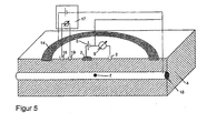
- FIG. 5 shows a schematic representation of another modified Embodiment of the invention.
- a Voltage drop in the electrolyte 4 detected by a current flow of the Counter electrode 3 is caused to distant defects of the pipe 16.
- One Controller 17 is coupled to the reference electrodes 18 and 19 and controls one between the formed as a guard ring auxiliary electrode 14 and the pipe 16 applied voltage such that the voltage between the reference electrodes 18 and 19 is set to 0V.
- the electric field effect on limits an area within the guard ring.
- a plurality of individual electrodes may be used as the auxiliary electrode be suitably in the direction of extension of the pipeline be arranged to limit the field effect.
- the corrosion can be used any electrochemical reaction in which a corrosion product is involved.
- the corrosion may also be a Coulometric detection of a reduction of a corrosion product done. So can reduce the amount of corrosion products in the presence of a completely oxidized Surface also by coulometric measurement of the reduction of Fe (III) to Fe (II) be determined.
- the choice of reaction or the given electrochemical Controlled variables become cathodic depending on the material protected plant, as well as the surrounding electrolyte.
Landscapes
- Chemical & Material Sciences (AREA)
- Life Sciences & Earth Sciences (AREA)
- Environmental Sciences (AREA)
- Physics & Mathematics (AREA)
- Metallurgy (AREA)
- Organic Chemistry (AREA)
- Materials Engineering (AREA)
- Biodiversity & Conservation Biology (AREA)
- Ecology (AREA)
- Environmental & Geological Engineering (AREA)
- Engineering & Computer Science (AREA)
- Mechanical Engineering (AREA)
- Health & Medical Sciences (AREA)
- Analytical Chemistry (AREA)
- Biochemistry (AREA)
- General Health & Medical Sciences (AREA)
- General Physics & Mathematics (AREA)
- Immunology (AREA)
- Pathology (AREA)
- Testing Resistance To Weather, Investigating Materials By Mechanical Methods (AREA)
- Investigating Or Analyzing Materials By The Use Of Electric Means (AREA)
Abstract
Eine Anordnung zum Erfassen von Wechselstromkorrosion an Abschnitten von
kathodisch geschützten Anlagen weist eine erste Elektrode (1) und eine weitere
Elektrode (3) auf. Ein Messwertaufnehmer (6) für eine elektrische Größe ist mit der
ersten Elektrode (1) elektrisch gekoppelt. Zwischen der ersten Elektrode (1) und der
zweiten Elektrode (3) befindet sich ein Elektrolyt (4), so dass die Elektroden (1, 3) in
Elektrolytverbindung stehen. Zwischen der ersten Elektrode (1) und der zweiten
Elektrode (3) ist eine Spannungsquelle (5) angeordnet, um an der ersten Elektrode
(1) eine elektrochemische Reaktion einzuleiten. Es ist weiterhin eine
Referenzelektrode (2) vorgesehen, die über den Elektrolyt (4) mit der ersten
Elektrode (1) in Elektrolytverbindung steht. Die erste Elektrode (1) ist eine Abschnitt
einer kathodisch geschützten Rohrleitung.

Description
Die vorliegende Erfindung betrifft ein Verfahren und eine Anordnung zum Erfassen von Wechselstromkorrosion an kathodisch geschützten Anlagen, wobei ein zu untersuchender Abschnitt der Anlage ein korrodierbares Material enthält, welches beim Auftreten von Wechselstromkorrosion zu einem Korrosionsprodukt reagiert.The present invention relates to a method and an arrangement for Acquisition of AC corrosion on cathodically protected equipment, with a to be examined section of the plant contains a corrodible material which reacts when AC corrosion occurs to a corrosion product.
Durch kathodischen Korrosionsschutz werden, erdverlegte Rohrleitungen und andere Anlagen in korrosiver Umgebung, bekanntlich vor Korrosion geschützt. Durch induzierte Wechselspannung in den Anlagen kann es jedoch trotz kathodischen Korrosionsschutzes zu Wechselstromkorrosion kommen.By cathodic corrosion protection, buried pipelines and other installations in corrosive environment, known to be protected against corrosion. However, induced AC voltage in the systems may cause it cathodic corrosion protection come to AC corrosion.
Die Kontrolle von erdverlegter Anlagen auf Korrosionsbefall ist problematisch. Dies liegt vor allem an der ungünstigen Zugänglichkeit der zu schützenden Anlagen. Es ist ein Verfahren zur Bestimmung des Rohrleitungs-Bodenpotentials an kathodisch geschützten Rohrleitungen bekannt, bei denen an verschiedenen Messpunkten entlang einer Rohrleitung eine Bezugselektrode über der Rohrleitung auf den Erdboden aufgesetzt wird (DE 100 21 994 A1 - Verfahren zur Bestimmung des Rohr/Bodenpotentials an kathodisch geschützten Rohrleitungen). Dieses Verfahren ist zur Detektion und quantitativen Erfassung von Wechselstromkorrosion jedoch nicht geeignet.The control of buried facilities for corrosion is problematic. This is mainly due to the unfavorable accessibility of the plants to be protected. It is a method of determining the pipeline bottom potential at cathodic protected pipelines, where at different Measuring points along a pipeline a reference electrode above the pipeline is placed on the ground (DE 100 21 994 A1 - Method of determination of the tube / ground potential on cathodically protected pipelines). This Method is for the detection and quantitative detection of AC corrosion but not suitable.
Für die Kontrolle des Korrosionszustandes von Rohrleitungen werden ferner Prüfstücke, sogenannte Coupons, im Bereich der Rohrleitung vergraben und elektrisch leitend mit dieser verbunden. Die Coupons sind meist beschichtete Stahlbleche mit einer Soll-Fehlstelle, in der Beschichtung. Letztere ist für den Korrosionszustand einer Fehlstelle in der benachbarten isolierten Rohrleitung repräsentativ. Messungen der Wechselstromdichte an dieser Soll-Fehlstelle ermöglichen Rückschlüsse auf das Auftreten von Wechselstromkorrosion. Durch das bekannte Verfahren ist jedoch nur eine momentane Erfassung der Wechselstromdichte möglich, nicht jedoch ein Bild über einen langfristig veränderlichen Korrosionszustandes der Rohrleitung zu gewinnen.For the control of the corrosion state of pipelines are further Test pieces, so-called coupons, buried in the area of the pipeline and electrically connected to this. The coupons are mostly coated Steel sheets with a target defect, in the coating. The latter is for the Corrosion state of a defect in the adjacent insulated pipe representative. Measurements of the AC current density at this target defect allow conclusions about the occurrence of AC corrosion. By the However, known method is only an instantaneous detection of AC density possible, but not a picture over a long term to gain variable corrosion state of the pipeline.
Ferner sind Potentialmessungen an den Coupons in Form von sogenannten Highspeed-Messungen bekannt. Die Coupons werden dazu von der Rohrleitung elektrisch entkoppelt, und das Potential des Coupons wird unmittelbar nach der Trennung gegen ein Standardpotential gemessen.Furthermore, potential measurements on the coupons are in the form of so-called High-speed measurements known. The coupons are from the pipeline electrically decoupled, and the potential of the coupon is immediately after the Separation against a standard potential measured.
Sämtliche bekannten Verfahren erlauben keine Erfassung des Korrosionszustandes von realen Fehlstellen an Rohrleitungen. All known methods do not allow detection of the Corrosion state of real defects on pipelines.
Aufgabe der vorliegenden Erfindung ist es, eine Detektion und quantitative Erfassung von Wechselstromkorrosion an kathodisch geschützten Anlagen zu verbessern.Object of the present invention is to provide a detection and quantitative Acquisition of AC corrosion on cathodically protected installations improve.
Ausgehend von einem Verfahren der eingangs genannten Art, wird diese
Aufgabe erfindungsgemäß dadurch gelöst, dass aus einem Teil der kathodisch
geschützten Anlage eine erste Elektrode gebildet wird, die eine Menge des
Korrosionsproduktes enthält und die erste Elektrode über einen Elektrolyten mit
wenigstens einer weiteren Elektrode in Elektrolytverbindung gebracht wird,
dass zwischen der ersten und der wenigstens einen weiteren Elektrode eine
elektrische Spannung angelegt wird, um eine elektrochemische Reaktion
einzuleiten,
wobei das Korrosionsprodukt der ersten Elektrode an der elektrochemischen
Reaktion teilnimmt und zu einem Reaktionsprodukt umgesetzt wird,
dass der Ablauf der Reaktion durch Einstellen wenigstens einer elektrischen
Größe an den Elektroden gesteuert wird,
dass wenigstens eine elektrische Messgröße aus einer aus Stromstärke,
Potentialdifferenz und Ladung bestehenden Messgrößengruppe erfasst wird, und
dass die Menge des in der Reaktion umgesetzten Korrosionsprodukts aus der
wenigstens einen elektrischen Messgröße ermittelt wird.Based on a method of the type mentioned, this object is achieved in that from a portion of the cathodically protected system, a first electrode is formed, which contains a quantity of the corrosion product and the first electrode via an electrolyte with at least one further electrode in electrolyte compound is brought
in that an electrical voltage is applied between the first and the at least one further electrode in order to initiate an electrochemical reaction,
wherein the corrosion product of the first electrode participates in the electrochemical reaction and is converted to a reaction product,
that the course of the reaction is controlled by adjusting at least one electrical quantity at the electrodes,
that at least one electrical measured quantity is detected from a group of measured variables consisting of current intensity, potential difference and charge, and
the amount of the corrosion product reacted in the reaction is determined from the at least one electrical measured variable.
Die Aufgabe wird erfindungsgemäß ferner durch eine Anordnung gemäß
Anspruch 14 gelöst.The object is further according to the invention by an arrangement according to
Die Auswahl der elektrischen Spannungsquelle kann nach den Umständen am Einsatzort und den gewünschten Messzeiten getroffen werden. Die Messgrößen müssen Rückschlüsse auf Art und/oder Menge des umgesetzten Korrosionsproduktes ermöglichen. Zu diesem Zweck können elektrische Strom- oder Spannungsquellen in Form eines Galvanostaten, eines Potentiostaten, einer Batterie oder eines Gleichstromnetzteils verwendet werden. Mit Hilfe eines Galvanostaten kann zum Beispiel ein Korrosionsprodukt bei einer vorgegebenen geregelten Stromstärke umgesetzt werden, wobei die zur Aufrechterhaltung der Stromstärke erforderliche Spannung gemessen wird. Aus der Stromstärke ist in Verbindung mit der Messzeit die geflossene Ladung zu ermitteln und bei Kenntnis der Art des Korrosionsproduktes durch coulometrische Berechnungen die Stoffmenge ermittelbar. Bei Kenntnis der aktiven Elektrodenfläche ist ferner eine flächenbezogene Stoffmenge oder flächenbezogene Ladungsmenge bestimmbar.The selection of the electrical voltage source may vary according to the circumstances Site and the desired measurement times are taken. The measured quantities must draw conclusions on the type and / or quantity of the implemented Allow corrosion product. For this purpose, electric power or Voltage sources in the form of a galvanostat, a potentiostat, a battery or a DC power supply. With the help of a galvanostat For example, a corrosion product may be at a given regulated current to be implemented, taking care to maintain the amperage required voltage is measured. From the amperage is in conjunction with the measuring time to determine the flowed charge and knowing the nature of the Corrosion product by coulometric calculations, the amount of substance determined. With knowledge of the active electrode surface is also a surface-related Quantity of substance or area-related amount of charge determinable.
Alternativ kann eine vorgegebene Spannung an die Elektroden angelegt und die Stromstärke erfasst werden. Dadurch kann zum Beispiel die Reaktion auf die Umsetzung einer Art von Korrosionsprodukt beschränkt werden, dessen Umsetzungsspannung bekannt ist.Alternatively, a predetermined voltage can be applied to the electrodes and the amperage is detected. Thus, for example, the reaction to the Implementation of a type of corrosion product to be limited Implementation voltage is known.
Es ist vorteilhaft, wenn zusätzlich zu der Erfassung der wenigstens einen elektrischen Messgröße eine Messzeit erfasst und die Menge des Korrosionsproduktes unter Berücksichtigung der Messzeit ermittelt wird.It is advantageous if, in addition to the detection, the at least one electrical quantity recorded a measuring time and the amount of Corrosion product is determined taking into account the measurement time.
Die Messzeit erlaubt weitere Auswertungen der elektrischen Messgröße. Beispielsweise kann zur Auswertung ein zeitlicher Messgrößenverlauf mit einer unter bekannten Bedingungen durchgeführten Referenzmessung verglichen werden. Ferner ist durch zeitliche Integration der gemessenen Stromstärke die Berechnung des Ladungsflusses möglich.The measuring time allows further evaluations of the electrical measured variable. For example, for evaluation a temporal measured variable course with a be compared under known conditions reference measurement. Furthermore, by temporal integration of the measured current strength, the calculation the charge flow possible.
Bei Verwendung eines mit dem zu untersuchenden Rohrleitungsabschnitt zeitweise verbundenen Prüfstücks (Coupons) kann die Messung des im Prüfstück enthaltenen Korrosionsproduktes an dem Ort stattfinden, an dem der Coupon an der Anlage angeordnet (z.B. vergraben) ist. Der Coupon ist üblicherweise für den Zeitraum der Messung elektrisch von der Anlage getrennt. Der Coupon kann alternativ von dem Abschnitt der Anlage entfernt werden und in einem Messelektrolyten in einem Messaufbau vermessen werden.When using a pipe section to be tested Temporarily connected test pieces (coupons) may be the measurement of the test piece contained corrosion product at the place where the coupon at the Plant is arranged (e.g., buried) plant. The coupon is usually for the Period of measurement electrically disconnected from the system. The coupon can Alternatively, be removed from the section of the system and in one Measuring electrolytes are measured in a test setup.
In alternativer Verfahrensweise kann als erste Elektrode ein Abschnitt einer kathodisch geschützten Rohrleitung verwendet werden. Die elektrochemische Reaktion findet dabei nicht an einer künstlichen Fehlstelle, sondern an einer realen Fehlstelle der Rohrleitung statt. Als Elektrolyt dient in diesem Fall üblicherweise das die Rohrleitung umgebende Medium (z.B. Erdreich, See- bzw. Meerwasser).In an alternative procedure, as the first electrode, a section of a cathodically protected piping can be used. The electrochemical Reaction does not find an artificial defect, but a real one Defective place of the pipeline. The electrolyte used in this case is usually the the pipeline surrounding medium (e.g., soil, seawater).
Vorzugsweise werden zum Steuern der elektrochemischen Reaktion drei Elektroden in einem elektrochemischen Drei-Elektroden-Aufbau mit Arbeits-, Gegen- und Referenzelektrode verwendet, wobei zwischen der Arbeitselektrode und der Referenzelektrode eine elektrische Potentialdifferenz gemessen wird.Preferably, to control the electrochemical reaction three Electrodes in a three-electrode electrochemical structure with working, and reference electrode, wherein between the working electrode and the Reference electrode, an electrical potential difference is measured.
Ein derartiger Messaufbau ist aus der physikalischen Chemie bzw. Elektrochemie bekannt. Die drei Elektroden werden derart gekoppelt, dass die Referenzelektrode in Elektrolytverbindung mit der Arbeitselektrode steht und zwischen diesen beiden Elektroden eine elektrische Potentialdifferenz gemessen wird. Da die Verbindung zwischen Arbeitselektrode und Referenzelektrode üblicherweise stromlos bleibt, ist diese Messung nicht durch Stromfluss beeinflußt. Ein Stromfluss findet nur zwischen Arbeitselektrode und Gegenelektrode statt. Als Referenzelektrode können handelsüblich verfügbare Referenz- bzw. Bezugselektroden verwendet werden, wie zum Beispiel Ag/AgCl oder Cu/CuSO4.Such a measuring structure is known from physical chemistry or electrochemistry. The three electrodes are coupled such that the reference electrode is in electrolyte communication with the working electrode and an electrical potential difference is measured between these two electrodes. Since the connection between the working electrode and the reference electrode usually remains currentless, this measurement is not affected by current flow. A current flow takes place only between the working electrode and the counter electrode. As the reference electrode, commercially available reference electrodes such as Ag / AgCl or Cu / CuSO 4 may be used .
Vorzugsweise wird in wenigstens einer Teilreaktion der elektrochemischen Reaktion eine Oxidation von Fe2+ zu Fe3+ ausgeführt. Preferably, in at least a partial reaction of the electrochemical reaction, oxidation of Fe 2+ to Fe 3+ is carried out.
Da die Mehrzahl der kathodisch geschützten Anlagen Eisen enthält, wird beim Auftreten von Wechselstromkorrosion oft metallisches Eisen zu zweiwertigen Eisen-Ionen oxidiert. In der Umgebung von erdvergrabenen kathodisch geschützten Anlagen liegen üblicherweise alkalische Bedingungen vor. Daher bildet sich aus den Eisen-Ionen schwerlösliches Eisenhydroxid, welches sich vor der Metalloberfläche ansammelt. In Gegenwart von Sauerstoff würde das zweiwertige Eisenhydroxid zum dreiwertigem Eisenhydroxid weiterreagieren; unter Einfluss des kathodischen Korrosionsschutzes ist diese Oxidationsreaktion jedoch meist unterbunden. Dies liegt einerseits daran, dass die Umgebung der Fehlstelle an Sauerstoff verarmt ist, da dieser durch den kathodischen Schutz reduziert wird; andererseits wird die Oxidation des zweiwertigen Eisenhydroxids durch den kathodischen Korrosionsschutz selbst unterbunden. An kathodisch geschützten Anlagen liegen folglich die Eisen-Ionen zumindest teilweise in zweiwertiger Form vor. Zur Detektion und Erfassung von Wechselstromkorrosion kann demnach der Nachweis von zweiwertigen Eisen-Ionen durch eine elektrochemisch gesteuerte Reaktion genutzt werden.Since the majority of cathodically protected equipment contains iron, the Occurrence of AC corrosion often metallic iron to divalent iron ions oxidized. In the area of buried, cathodically protected Plants are usually alkaline conditions. Therefore, forms from the Iron ion poorly soluble iron hydroxide, which is located in front of the metal surface accumulates. In the presence of oxygen, the divalent iron hydroxide would become continue to react with trivalent iron hydroxide; under the influence of the cathodic Corrosion protection, however, this oxidation reaction is usually prevented. This partly because the environment of the defect is depleted of oxygen, since this is reduced by the cathodic protection; On the other hand, the Oxidation of the divalent iron hydroxide by the cathodic Corrosion protection even prevented. At cathodically protected plants lie consequently, the iron ions at least partially in divalent form. For detection and detection of AC corrosion can therefore be the detection of divalent iron ions utilized by an electrochemically controlled reaction become.
Die Arbeitselektrode mit der Fehlstelle wird durch Anlegen einer Spannung derart anodisch polarisiert, dass eine Oxidationsreaktion von vorhandenen zweiwertigen Eisen-Ionen zu dreiwertigen Eisen-Ionen erfolgt.The working electrode with the defect is created by applying a voltage such anodically polarized that an oxidation reaction of existing divalent iron ions to trivalent iron ions occurs.
Es ist vorteilhaft, wenn ein Spannungsabfall im Elektrolyten zwischen der ersten und einer weiteren Elektrode durch Erfassen einer Polarisationspotentialdifferenz ermittelt und als Korrekturgröße verwendet wird.It is advantageous if a voltage drop in the electrolyte between the first and another electrode by detecting a Polarization potential difference determined and used as a correction variable.
In den meisten Fällen von erdvergrabenen Anlagen oder Rohrleitungen ist bei der Anwendung der Erfindung der Spannungsabfall im Elektrolyten bzw. dem Erdreich zu berücksichtigen. Eine Bestimmung des wahren Potentials der Arbeitselektrode ist aufgrund der Verfälschung durch diesen Spannungsabfall nicht immer direkt möglich. Es kann jedoch eine Korrekturgröße ermittelt werden, indem der Stromfluss zwischen Arbeitselektrode und Gegenelektrode unterbrochen wird und die Spannungsdifferenz zwischen Arbeitselektrode und Referenzelektrode unmittelbar nach dem Unterbrechen bestimmt wird.In most cases of buried facilities or pipelines is included the application of the invention, the voltage drop in the electrolyte or the To consider soil. A determination of the true potential of Working electrode is not due to the falsification by this voltage drop always directly possible. However, a correction quantity can be determined by the current flow between the working electrode and the counter electrode is interrupted and the voltage difference between the working electrode and the reference electrode is determined immediately after the interruption.
Vorzugsweise wird ein Messzyklus ausgeführt, wobei zwischen der ersten und der wenigstens einen weiteren Elektrode für eine ersten Zeitdauer eine Spannung angelegt wird, und danach die Verbindung zwischen der ersten und der wenigstens einen weiteren Elektrode für eine zweite Zeitdauer getrennt und die Polarisationspotentialdifferenz ermittelt wird.Preferably, a measurement cycle is performed, wherein between the first and the at least one further electrode for a first period of time a voltage is created, and then the connection between the first and the at least separated another electrode for a second period of time and the Polarization potential difference is determined.
Typische Zeitteilungen für einen Messzyklus betragen zwei bis zehn, z.B. fünf Sekunden Stromfluss zwischen Arbeitselektrode und Gegenelektrode und 0.1 bis 2 Sekunden Unterbrechung. Die Messung der Polarisationspotentialdifferenz, also die so erfasste Spannung zwischen Arbeitselektrode und Referenzelektrode, erfolgt beispielsweise zwischen 10 ns und 1 s nach Unterbrechen des Stromflusses.Typical time divisions for one measurement cycle are two to ten, e.g. five Seconds current flow between working electrode and counter electrode and 0.1 to 2 Seconds interruption. The measurement of the polarization potential difference, ie the thus detected voltage between the working electrode and the reference electrode, takes place for example, between 10 ns and 1 s after interrupting the flow of current.
Es ist vorteilhaft, wenn der Messzyklus periodisch ausgeführt wird.It is advantageous if the measuring cycle is carried out periodically.
In Weiterbildung der Erfindung wird wenigstens eine Hilfselektrode von der ersten Elektrode beabstandet angeordnet und die Hilfselektrode über eine elektrische Spannungsquelle mit der ersten Elektrode derart elektrisch gekoppelt, dass eine elektrische Feldwirkung der ersten und der weiteren Elektrode auf einen begrenzten Abschnitt der kathodisch geschützten Anlage konzentriert wird.In development of the invention, at least one auxiliary electrode of the spaced electrode disposed and the auxiliary electrode via a electrical voltage source is electrically coupled to the first electrode in such a way that that an electric field effect of the first and the further electrode on a concentrated portion of the cathodic protected plant is concentrated.
Durch diese Weiterbildung kann sichergestellt werden, dass der Strom nur aus der zu untersuchenden Fehlstelle austritt und die Messung der Wechselstromkorrosion nur diese Fehlstelle berücksichtigt. Durch die Konzentration der elektrischen Feldwirkung mit einer Hilfselektrode wird gewährleistet, dass primär die Fehlstelle in der Rohrleitung polarisiert wird und weiter entfernte Fehlstellen nicht zum Messergebnis beitragen.Through this training, it can be ensured that the electricity is only off the defect to be examined emerges and the measurement of the AC corrosion considered only this flaw. By the concentration The electric field effect with an auxiliary electrode ensures that primary the defect in the pipeline is polarized and farther away defects are not contribute to the measurement result.
Vorzugsweise wird als Hilfselektrode eine die weitere Elektrode mit Abstand ringförmig umgebende Elektrode verwendet.Preferably, as the auxiliary electrode, the further electrode is at a distance annular surrounding electrode used.
Die Hilfselektrode ist ringförmig um die weitere Elektrode herum angeordnet und begrenzt die elektrische Feldwirkung der zwischen der ersten und der weiteren Elektrode angelegten Spannung im wesentlichen auf den inneren Ringraum. Dadurch werden entfernte Fehlstellen der Anlage, die nicht durch die Messung erreicht werden sollen, schwächer polarisiert und nehmen an der coulometrischen Erfassung des Korrosionsproduktes an der Fehlstelle nicht teil.The auxiliary electrode is arranged annularly around the further electrode and limits the electric field effect between the first and the other Electrode applied voltage substantially to the inner annulus. This will remove distant imperfections of the plant, not by the measurement should be achieved, weaker polarized and participate in the coulometric Detection of the corrosion product at the defect not part.
Weitere vorteilhafte Ausführungen der Erfindung ergeben sich aus den Unteransprüchen.Further advantageous embodiments of the invention will become apparent from the Dependent claims.
Im folgenden wird die Erfindung anhand der beiliegenden Zeichnungen näher
erläutert. In den Zeichnungen zeigt:
Figur 1 veranschaulicht ein einfaches Ausführungsbeispiel eines Messaufbaus
zur Erfassung der Wechselstromkorrosion, wobei ein Drei-Elektroden-Aufbau
verwendet wird. Eine Arbeitselektrode 1, eine Referenzelektrode 2 und eine
Gegenelektrode 3 stehen über einen Elektrolyten 4 miteinander in Elektrolytverbindung.
Zwischen der Arbeitselektrode 1 und der Referenzelektrode 2 ist ein
Messwertaufnehmer in Form eines Spannungsmessgeräts 6 angeordnet. Eine
Spannungsquelle 5 ist einerseits mit der Arbeitselektrode 1 und andererseits mit der
Gegenelektrode 3 verbunden. Eine Soll-Spannung bzw. Soll-Potentialdifferenz wird
mittels der Spannungsquelle 5 zwischen der Arbeitselektrode 1 und der
Referenzelektrode 2 angelegt. Dabei kommt es zwischen der Arbeitselektrode 1 und
der Gegenelektrode 3 zu einem Stromfluss durch den Elektrolyten 4 und zu einer
elektrochemischen Reaktion an der Arbeitselektrode 1 bzw. der Gegenelektrode 3.
Die Gegenelektrode 3 kann als verzinkter Erdspieß ausgebildet sein, der in den den
Elektrolyten bildenden Erdboden 4 getrieben wird. Stattdessen kann aber auch eine
Rohrleitung oder ein Erdungssystem eines Gebäudes als Gegenelektrode
verwendet werden. Vorzugsweise ist die Oberfläche der Gegenelektrode 3
bedeutend größer als die der Arbeitselektrode 1. Der Elektrolyt 4 kann aus
Erdboden, Seewasser oder dergleichen bestehen.FIG. 1 illustrates a simple exemplary embodiment of a measurement setup
for detecting AC corrosion, using a three-electrode design
is used. A working
Figur 2 zeigt in einem Diagramm die Messergebnisse coulometrischer
Messungen von Korrosionsprodukten an Prüfstücken (Coupons). Die Messungen
wurden mit einem in Figur 1 dargestellten Messaufbau vorgenommen. Die
vermessenen Coupons hatten eine Fläche von ca. 1 cm2 und wurden in einem
Elektrolyten, der aus künstlichem Boden bestand, für sieben Tage gelagert. Dabei
wurden die Coupons kathodisch geschützt und mit unterschiedlichen
Wechselstromdichten beaufschlagt. Die Wechselstromdichte an Coupon (a) betrug 0
A/m2 und an Coupon (b) 100 A/m2. Vor der Messung wurden die Coupons vom
kathodischen Schutz und der Wechselstromquelle getrennt. Für die Messung wurde
mit Hilfe eines Galvanostaten (Spannungsquelle 5) ein konstanter anodischer Strom
von 100 µA zwischen dem als Arbeitselektrode 1 eingesetzten Coupon und der
Gegenelektrode 3 eingeprägt. Die Potentialdifferenz wurde durch Spannungsmessung
zwischen der Arbeitselektrode 1 und der Referenzelektrode 2 mit einem
Voltmeter 6 bestimmt. Die Steuerung des Galvanostaten und die Erfassung des
Polarisationspotentials erfolgte durch einen Rechner. Die Messdauer für Coupon (b)
betrug 330 Sekunden. Aus dem im Diagram dargestellten Kurvenverlauf ist
ersichtlich, daß das Potential mit zunehmendem Ladungsfluss zunächst ansteigt und
in dem mit 7 bezeichneten Bereich eine geringere Potentialsteigung aufweist. In
diesem Bereich erfolgt die Oxidation von zweiwertigen Eisen-Ionen zu dreiwertigen
Eisen-Ionen. Bei zunehmenden Ladungsfluss wurde ein steiler, mit 8 bezeichneter
Anstieg des Potentials beobachtet. Diese Potentialzunahme endet mit dem
Einsetzen der Sauerstoffentwicklung bei 9. Mit weiterer Ladung bleibt das Potential
nahezu konstant.FIG. 2 shows in a diagram the measurement results of coulometric measurements of corrosion products on test pieces (coupons). The measurements were made with a measuring setup shown in FIG. The measured coupons had an area of about 1 cm 2 and were stored in an electrolyte consisting of artificial soil for seven days. The coupons were protected cathodically and subjected to different AC densities. The AC density on coupon (a) was 0 A / m 2 and on coupon (b) 100 A / m 2 . Before the measurement, the coupons were disconnected from the cathodic protection and the AC source. For the measurement, a constant anodic current of 100 μA was impressed between the coupon used as working
Im Potentialverlauf von Coupon (a) erfolgt der dem Anstieg 8 entsprechende
und mit 10 bezeichneter Anstieg bei bedeutend kleineren Ladungsmengen. Die
Sauerstoffentwicklung 11 erfolgt beim gleichen Potential wie bei Coupon (b). Nach
der Messung wurden die Coupons optisch untersucht. Auf Coupon (a) wurden
keinerlei Korrosionsangriffe gefunden, während Coupon (b) starke Korrosion zeigte.
Die vom Ladungsfluss abhängige Lage des Beginns des steilen Anstiegs des
Potentials ist bei dieser Messanordnung repräsentativ für die Menge oxidierten
zweiwertigen Eisens und damit das Ausmaß der Wechselstromkorrosion an den
Coupons. Ferner kann aus dem Einsatzpotential der Sauerstoffentwicklung 9 bzw.
11 eine Information über den pH-Wert gewonnen werden.In the potential course of coupon (a) of the
Figur 3 zeigt ein Diagramm der Messung einer Wechselstromkorrosion an
einem erdvergrabenen Coupon, der 2,5 Jahre mit einer kathodisch geschützten
Rohrleitung elektrisch verbunden und vergraben war. Die Wechselstromdichte am
Coupon lag im Bereich von 120 A/m2. Vor der Messung wurde die Verbindung des
Coupons zur Rohrleitung unterbrochen. Für die Messung wurde ein anodischer
Strom von 50 mA zwischen dem Coupon als Arbeitselektrode 1 und der
Gegenelektrode 3 eines Galvanostaten 5 angelegt. Da der Spannungsabfall im
Elektrolyten signifikant und zu berücksichtigen war, wurde der Strom in periodischen
Abständen von 5 Sekunden für jeweils eine Sekunde unterbrochen. Die
Potentialdifferenz zwischen der Arbeitselektrode 1 und der Referenzelektrode 2
wurde unmittelbar vor und nach dem Unterbrechen mit einem Voltmeter 6 bestimmt.
Der Kurvenverlauf (c) gibt die jeweils vor der Unterbrechung aufgenommenen
Potentialwerte wieder, während der Kurvenverlauf (d) die Potentialwerte nach dem
Unterbrechen des Stroms zeigt. Der Kurvenverlauf (d), gebildet durch die
Potentialwerte, die nicht durch den Elektrolytwiderstand beeinflusst sind, zeigt gute
Übereinstimmung mit dem in Figur 2 gezeigten Potentialverlauf. Eine Unterbrechung
des Stroms erlaubt die Bestimmung des Potentials des Coupons ohne störende
Einflüsse des Spannungsabfalls im Elektrolyten.FIG. 3 shows a diagram of the measurement of AC corrosion on an earth-buried coupon that was electrically connected and buried for 2.5 years with a cathodically protected pipe. The AC density at the coupon was in the range of 120 A / m 2 . Before the measurement, the connection of the coupon to the pipeline was interrupted. For the measurement, an anodic current of 50 mA was applied between the coupon as the working
Bei dem unter realen Bedingungen und für eine Dauer von 2,5 Jahren
eingesetzten Coupons erforderte der mit 12 bezeichnete Anstieg des Potentials etwa
300 mal mehr Ladung als der Anstieg 8 aus Figur 2. Under real conditions and for a duration of 2.5 years
used coupons required the designated 12 potential increase about
300 times more charge than the
Wird der Coupon nach der Messung erneut mit der Rohrleitung verbunden, so wirkt der kathodische Schutz der Rohrleitung wieder auf den Coupon, und die im Verlauf der Messung oxidierten Eisen-Ionen werden wieder reduziert. Eine wiederholte Messung zu einem späteren Zeitpunkt ist mit guter Reproduzierbarkeit möglich. Das Verfahren ist für die wiederholte Messung des Korrosionszustandes an einem Coupon geeignet.If the coupon is reconnected to the pipeline after the measurement, then The cathodic protection of the pipe again acts on the coupon, and the in Course of measurement oxidized iron ions are reduced again. A Repeated measurement at a later date is with good reproducibility possible. The method is for the repeated measurement of the corrosion state a coupon suitable.
Figur 4 zeigt eine schematische Darstellung eines abgewandelten
Ausführungsbeispiels eines Messaufbaus zur Erfassung der Wechselstromkorrosion
an einer die erste Elektrode bildenden Fehlstelle 1' auf einer Rohrleitung 16. Die
Fehlstelle 1', die Referenzelektrode 2 und die Gegenelektrode 3 befinden sich in
Kontakt mit dem Elektrolyten 4 und stehen über diesen miteinander in Elektrolytverbindung.
Eine Spannungsquelle 5 ermöglicht die Einstellung einer Spannung bzw.
eines Stromes zwischen der Fehlstelle und der Fehlstelle 1' und der Gegenelektrode
3, und ein als Spannungsmessgerät ausgebildeter Messwertaufnehmer 6 nimmt die
Spannung zwischen der Referenzelektrode 2 und der Fehlstelle 1' auf.Figure 4 shows a schematic representation of a modified
Embodiment of a measuring structure for detecting the AC corrosion
on a defect forming the first electrode 1 'on a
Aufgrund der unterirdischen Erstreckung der Rohrleitung 16 ist die Feld- bzw.
Stromverteilung unbekannt. Es ist nicht auszuschließen, dass weitere Fehlstellen in
der Rohrleitung 16 mit der Gegenelektrode 3 in Elektrolytverbindung stehen und
zum Stromfluss beitragen.Due to the underground extent of the
Um die elektrische Feldwirkung auf einen Umgebungsbereich der zu
untersuchende Fehlstelle 1' einzugrenzen, ist eine Hilfselektrode 14 über eine in
einem Potentiostaten 15 angeordnete Spannungsquelle mit der Rohrleitung 16
gekoppelt. Mit dem Potentiostaten ist eine zweite Referenzelektrode 13 verbunden.
Die Hilfselektrode 14 umgibt ringförmig die Gegenelektrode 3 und die
Referenzelektrode 2. Die Hilfselektrode 14 ist ferner derart angeordnet, dass sich
auch die Fehlstelle 1' in dem inneren Ringraum befindet, bei erdverlegten Anlagen
jedoch meist unterhalb der Ringebene. Eine derartige ringförmige Elektrode wird
auch als Guardring bezeichnet. Um die Feldwirkung auf den Bereich innerhalb des
Guardrings zu beschränken, wird das Potential außerhalb des Rings mit die
Referenzelektrode 13 gemessen und eine Spannung zwischen dem Guardring 14
und der Rohrleitung 16 derart gesteuert, dass das von der Referenzelektrode 13
gemessene Potential im wesentlichen konstant gehalten wird. Die zwischen dem
Guardring 14 und der Rohrleitung 16 angelegte Spannung ruft einen
widerstandsabhängigen Stromfluß hervor. Dieser entspricht dem Teilstrom, der von
der Gegenelektrode 3 in entfernte Fehlstellen fließt. Der Guardring 14 kann aus
einer einzelnen, flächigen Elektrode oder aus mehreren, untereinander verbundenen
Elektroden gebildet sein. To the electric field effect on a surrounding area of the
to narrow down the investigative defect 1 'is an
Figur 5 zeigt eine schematische Darstellung eines weiteren abgewandelten
Ausführungsbeispiels der Erfindung. Mit zwei Referenzelektroden 18 und 19 wird ein
Spannungsabfall im Elektrolyten 4 erfasst, der durch einen Stromfluß von der
Gegenelektrode 3 zu entfernten Fehlstellen der Rohrleitung 16 verursacht wird. Ein
Steuergerät 17 ist mit den Referenzelektroden 18 und 19 gekoppelt und steuert eine
zwischen der als Guardring ausgebildeten Hilfselektrode 14 und der Rohrleitung 16
angelegte Spannung derart, dass die Spannung zwischen den Referenzelektroden
18 und 19 auf 0 V eingestellt wird. Dadurch wird die elektrische Feldwirkung auf
einen Bereich innerhalb des Guardrings begrenzt.Figure 5 shows a schematic representation of another modified
Embodiment of the invention. With two
Im Rahmen des Erfindungsgedankens sind weitere Abwandlungen möglich. Beispielsweise können als Hilfselektrode mehrere Einzelelektroden verwendet werden, die in geeigneter Weise in der Erstreckungsrichtung der Rohrleitung angeordnet werden, um die Feldwirkung zu beschränken. Ferner kann zur Erfassung der Korrosion jede beliebige elektrochemische Reaktion verwendet werden, bei der ein Korrosionsprodukt beteiligt ist. Im Rahmen der Erfindung kann auch eine coulometrische Erfassung einer Reduktion eines Korrosionsproduktes erfolgen. So kann die Menge an Korrosionsprodukten bei Vorliegen einer komplett oxidierten Oberfläche auch durch coulometrische Messung der Reduktion von Fe(III) zu Fe(II) bestimmt werden. Die Auswahl der Reaktion bzw. der vorgegebenen elektrochemischen Regelgrößen wird in Abhängigkeit von dem Material der kathodisch geschützten Anlage, sowie dem umgebenden Elektrolyten getroffen.Within the scope of the inventive concept further modifications are possible. For example, a plurality of individual electrodes may be used as the auxiliary electrode be suitably in the direction of extension of the pipeline be arranged to limit the field effect. Furthermore, for detection the corrosion can be used any electrochemical reaction in which a corrosion product is involved. In the context of the invention may also be a Coulometric detection of a reduction of a corrosion product done. So can reduce the amount of corrosion products in the presence of a completely oxidized Surface also by coulometric measurement of the reduction of Fe (III) to Fe (II) be determined. The choice of reaction or the given electrochemical Controlled variables become cathodic depending on the material protected plant, as well as the surrounding electrolyte.
Claims (20)
dadurch gekennzeichnet, dass aus einem Teil der Anlage eine erste Elektrode gebildet wird, die eine Menge des Korrosionsproduktes enthält,
dass die erste Elektrode über einen Elektrolyt mit wenigstens einer weiteren Elektrode in Elektrolytverbindung gebracht wird,
dass zwischen der ersten und der wenigstens einen weiteren Elektrode eine elektrische Spannung angelegt wird, um eine elektrochemische Reaktion einzuleiten,
wobei das Korrosionsprodukt der ersten Elektrode an der elektrochemischen Reaktion teilnimmt und zu einem Reaktionsprodukt umgesetzt wird,
wobei der Ablauf der Reaktion durch Einstellen wenigstens einer elektrischen Größe an den Elektroden gesteuert wird,
wobei wenigstens eine elektrische Messgröße aus einer aus Stromstärke, Potentialdifferenz und Ladung bestehenden Messgrößengruppe erfasst wird,
wobei die Menge des in der Reaktion umgesetzten Korrosionsproduktes aus der wenigstens einen Messgröße ermittelt wird.A method of detecting AC corrosion on cathodically protected equipment, wherein a portion of the equipment to be tested contains a corrodible material which reacts to a corrosion product when AC corrosion occurs,
characterized in that from a part of the plant a first electrode is formed, which contains a quantity of the corrosion product,
that the first electrode is brought into electrolyte communication with at least one further electrode via an electrolyte,
in that an electrical voltage is applied between the first and the at least one further electrode in order to initiate an electrochemical reaction,
wherein the corrosion product of the first electrode participates in the electrochemical reaction and is converted to a reaction product,
wherein the course of the reaction is controlled by adjusting at least one electrical quantity at the electrodes,
wherein at least one electrical measured quantity is detected from a group of measured variables consisting of current intensity, potential difference and charge,
wherein the amount of reacted in the reaction corrosion product is determined from the at least one measured variable.
zwischen der ersten und der wenigstens einen weiteren Elektrode für eine erste Zeitdauer eine Spannung angelegt wird, und danach
die Verbindung zwischen der ersten und der wenigstens einen weiteren Elektrode für eine zweite Zeitdauer getrennt und die Polarisationspotentialdifferenz ermittelt wird.A method according to claim 9, characterized in that a measuring cycle is carried out, wherein
a voltage is applied between the first and at least one further electrodes for a first period of time, and thereafter
the connection between the first and the at least one further electrode is separated for a second time duration and the polarization potential difference is determined.
dass die Hilfselektrode über eine elektrische Spannungsquelle mit der ersten Elektrode elektrisch derart gekoppelt wird, dass eine elektrische Feldwirkung der ersten und der weiteren Elektrode auf einen begrenzten Abschnitt der kathodisch geschützten Anlage konzentriert wird.Method according to one of claims 7 to 11, characterized in that at least one auxiliary electrode is arranged at a distance from the first electrode,
in that the auxiliary electrode is electrically coupled to the first electrode via an electrical voltage source in such a way that an electric field effect of the first and the further electrode is concentrated on a limited section of the cathodically protected plant.
einer ersten Elektrode (1), wenigstens einer weiteren Elektrode (3) und einem Meßwertaufnehmer (6) für eine elektrische Größe, der mit wenigstens einer der beiden Elektroden (1,3) elektrisch gekoppelt ist,
wobei zwischen der ersten Elektrode (1) und der wenigstens einen weiteren Elektrode ein Elektrolyt (4) angeordnet ist, über den die Elektroden (1,3) in Elektrolytverbindung stehen,
dadurch gekennzeichnet, dass zwischen der ersten Elektrode (1) und der wenigstens einen weiteren Elektrode (3) eine Spannungsquelle (5) vorgesehen ist, um wenigstens an der ersten Elektrode (1) eine elektrochemische Reaktion einzuleiten.Arrangement for detecting AC corrosion on sections of cathodically protected installations, with
a first electrode (1), at least one further electrode (3) and a measuring transducer (6) for an electrical quantity which is electrically coupled to at least one of the two electrodes (1, 3),
wherein between the first electrode (1) and the at least one further electrode an electrolyte (4) is arranged, over which the electrodes (1, 3) are in electrolyte communication,
characterized in that a voltage source (5) is provided between the first electrode (1) and the at least one further electrode (3) in order to initiate an electrochemical reaction at least at the first electrode (1).
Applications Claiming Priority (2)
| Application Number | Priority Date | Filing Date | Title |
|---|---|---|---|
| DE102004025343 | 2004-05-19 | ||
| DE200410025343 DE102004025343A1 (en) | 2004-05-19 | 2004-05-19 | Method and device for detecting AC corrosion on cathodically protected installations |
Publications (2)
| Publication Number | Publication Date |
|---|---|
| EP1598446A2 true EP1598446A2 (en) | 2005-11-23 |
| EP1598446A3 EP1598446A3 (en) | 2006-07-19 |
Family
ID=34935340
Family Applications (1)
| Application Number | Title | Priority Date | Filing Date |
|---|---|---|---|
| EP05008456A Withdrawn EP1598446A3 (en) | 2004-05-19 | 2005-04-19 | Process and system for detecting alternating stray current corrosion in cathodically protected plants |
Country Status (2)
| Country | Link |
|---|---|
| EP (1) | EP1598446A3 (en) |
| DE (1) | DE102004025343A1 (en) |
Cited By (2)
| Publication number | Priority date | Publication date | Assignee | Title |
|---|---|---|---|---|
| FR2983582A1 (en) * | 2011-12-05 | 2013-06-07 | Gdf Suez | MONITORING OF A BURED CANALIZATION SUBJECT TO CATHODIC PROTECTION |
| US11598714B1 (en) * | 2021-06-17 | 2023-03-07 | Matergenics, Inc. | Alternating current interference corrosion detector |
Families Citing this family (2)
| Publication number | Priority date | Publication date | Assignee | Title |
|---|---|---|---|---|
| DE102015105410A1 (en) | 2015-04-09 | 2016-10-13 | Endress + Hauser Conducta Gesellschaft für Mess- und Regeltechnik mbH + Co. KG | Device for monitoring the dissolution of a sample material |
| CN108982343B (en) * | 2018-08-07 | 2021-07-06 | 中国石油大学(华东) | An experimental device for in-situ observation of stray current corrosion morphology |
Family Cites Families (3)
| Publication number | Priority date | Publication date | Assignee | Title |
|---|---|---|---|---|
| US5469048A (en) * | 1994-06-13 | 1995-11-21 | Meridian Oil Inc. | Cathodic protection measurement apparatus |
| EP1152235A1 (en) * | 2000-05-04 | 2001-11-07 | Ionpro N.V. | System to measure the state of corrosion of buried metallic structures continuously in time and in length |
| DE10021994A1 (en) * | 2000-05-05 | 2001-11-08 | Ruhrgas Ag | Arrangement for determining the pipe/ground potential on cathodically protected pipelines comprises measuring value receivers for acquiring measured and reference values for the pipe/ground potential |
-
2004
- 2004-05-19 DE DE200410025343 patent/DE102004025343A1/en not_active Withdrawn
-
2005
- 2005-04-19 EP EP05008456A patent/EP1598446A3/en not_active Withdrawn
Cited By (3)
| Publication number | Priority date | Publication date | Assignee | Title |
|---|---|---|---|---|
| FR2983582A1 (en) * | 2011-12-05 | 2013-06-07 | Gdf Suez | MONITORING OF A BURED CANALIZATION SUBJECT TO CATHODIC PROTECTION |
| EP2602609A1 (en) * | 2011-12-05 | 2013-06-12 | Gdf Suez | Monitoring of a pipeline under cathodic protection |
| US11598714B1 (en) * | 2021-06-17 | 2023-03-07 | Matergenics, Inc. | Alternating current interference corrosion detector |
Also Published As
| Publication number | Publication date |
|---|---|
| DE102004025343A1 (en) | 2005-12-08 |
| EP1598446A3 (en) | 2006-07-19 |
Similar Documents
| Publication | Publication Date | Title |
|---|---|---|
| DE2612498C2 (en) | Method and device for measuring the polarization potential of a metal object arranged in an electrolyte in a current field | |
| DE60220035T2 (en) | SENSOR ARRAY DEVICE AND METHOD FOR MONITORING ELECTROCHEMICAL CORROSION | |
| DE3010750C2 (en) | ||
| DE4223228C2 (en) | Methods for the determination of peracids | |
| DE2916934C2 (en) | Method and device for maintaining cathodic protection against corrosion | |
| DE2729115A1 (en) | METHOD AND DEVICE FOR DETERMINING THE EFFECTIVE CONCENTRATION OF AN ELECTROACTIVE COMPONENT | |
| DE102019120446A1 (en) | Method for correcting two measured values from different analytical measuring devices and measuring point for carrying out the method | |
| DE69315948T2 (en) | Method and device for measuring localized corrosion under depots or metal corrosion rates under loose deposits in cooling water systems | |
| DE3135639A1 (en) | Method for measuring the potential with respect to the ground of a cathodically protected metal structure | |
| DE102016222538B3 (en) | Method and arrangement for assessing the corrosion and passivation of the reinforcement taking into account the moisture in reinforced concrete | |
| EP3271699A1 (en) | Process and device for characterizing a coolant | |
| EP2605007B1 (en) | Method for cleaning electrode surfaces | |
| EP1598446A2 (en) | Process and system for detecting alternating stray current corrosion in cathodically protected plants | |
| DE69318933T2 (en) | Process for the detection of essential constituents in other plating baths containing lowering constituents | |
| DE2241648A1 (en) | Cathodic protection potential measuring device - comprises steel insert tube fitted with measuring cathode and reference anode | |
| DE2033619B2 (en) | Measuring device for determining the rate of corrosion of metals and corrosive media | |
| DE1498996A1 (en) | Device and method for in-situ measurement of the harmful effects of the surrounding environment on a metallic material | |
| WO2016074836A1 (en) | Conveying hose | |
| EP0551544B1 (en) | Method for monitoring the state of corrosion of metallic pillars and posts, embedded in concrete foundations | |
| DE69127685T2 (en) | Method and device for checking the electrical insulation status of an electrically conductive structure | |
| DE2707265C2 (en) | Measuring device for determining the metal / soil potential of cathodically protected metal bodies | |
| EP2390383A2 (en) | Method for detecting damage to the casing of objects laid in soil and/or bodies of water and protected by cathodic corrosion protection | |
| DE102017104971A1 (en) | Method for determining an ozone concentration in an aqueous solution | |
| DE69410622T2 (en) | IMPROVEMENTS IN MERCURY ELECTRODES | |
| DE102017223707A1 (en) | Method and control device for the automated, continuous and self-sufficient determination of the oxygen concentration in the waste water of a decentralized wastewater treatment plant |
Legal Events
| Date | Code | Title | Description |
|---|---|---|---|
| PUAI | Public reference made under article 153(3) epc to a published international application that has entered the european phase |
Free format text: ORIGINAL CODE: 0009012 |
|
| AK | Designated contracting states |
Kind code of ref document: A2 Designated state(s): AT BE BG CH CY CZ DE DK EE ES FI FR GB GR HU IE IS IT LI LT LU MC NL PL PT RO SE SI SK TR |
|
| AX | Request for extension of the european patent |
Extension state: AL BA HR LV MK YU |
|
| PUAL | Search report despatched |
Free format text: ORIGINAL CODE: 0009013 |
|
| AK | Designated contracting states |
Kind code of ref document: A3 Designated state(s): AT BE BG CH CY CZ DE DK EE ES FI FR GB GR HU IE IS IT LI LT LU MC NL PL PT RO SE SI SK TR |
|
| AX | Request for extension of the european patent |
Extension state: AL BA HR LV MK YU |
|
| 17P | Request for examination filed |
Effective date: 20061127 |
|
| AKX | Designation fees paid |
Designated state(s): AT BE BG CH CY CZ DE DK EE ES FI FR GB GR HU IE IS IT LI LT LU MC NL PL PT RO SE SI SK TR |
|
| 17Q | First examination report despatched |
Effective date: 20080225 |
|
| STAA | Information on the status of an ep patent application or granted ep patent |
Free format text: STATUS: THE APPLICATION IS DEEMED TO BE WITHDRAWN |
|
| 18D | Application deemed to be withdrawn |
Effective date: 20111101 |