EP1598318A1 - Electric deionization apparatus and method of operating the same - Google Patents
Electric deionization apparatus and method of operating the same Download PDFInfo
- Publication number
- EP1598318A1 EP1598318A1 EP04711002A EP04711002A EP1598318A1 EP 1598318 A1 EP1598318 A1 EP 1598318A1 EP 04711002 A EP04711002 A EP 04711002A EP 04711002 A EP04711002 A EP 04711002A EP 1598318 A1 EP1598318 A1 EP 1598318A1
- Authority
- EP
- European Patent Office
- Prior art keywords
- water
- chamber
- concentrating
- desalting
- electrodeionization apparatus
- Prior art date
- Legal status (The legal status is an assumption and is not a legal conclusion. Google has not performed a legal analysis and makes no representation as to the accuracy of the status listed.)
- Withdrawn
Links
Images




Classifications
-
- C—CHEMISTRY; METALLURGY
- C02—TREATMENT OF WATER, WASTE WATER, SEWAGE, OR SLUDGE
- C02F—TREATMENT OF WATER, WASTE WATER, SEWAGE, OR SLUDGE
- C02F1/00—Treatment of water, waste water, or sewage
- C02F1/46—Treatment of water, waste water, or sewage by electrochemical methods
- C02F1/469—Treatment of water, waste water, or sewage by electrochemical methods by electrochemical separation, e.g. by electro-osmosis, electrodialysis, electrophoresis
- C02F1/4693—Treatment of water, waste water, or sewage by electrochemical methods by electrochemical separation, e.g. by electro-osmosis, electrodialysis, electrophoresis electrodialysis
- C02F1/4695—Treatment of water, waste water, or sewage by electrochemical methods by electrochemical separation, e.g. by electro-osmosis, electrodialysis, electrophoresis electrodialysis electrodeionisation
-
- B—PERFORMING OPERATIONS; TRANSPORTING
- B01—PHYSICAL OR CHEMICAL PROCESSES OR APPARATUS IN GENERAL
- B01D—SEPARATION
- B01D61/00—Processes of separation using semi-permeable membranes, e.g. dialysis, osmosis or ultrafiltration; Apparatus, accessories or auxiliary operations specially adapted therefor
- B01D61/42—Electrodialysis; Electro-osmosis ; Electro-ultrafiltration; Membrane capacitive deionization
- B01D61/44—Ion-selective electrodialysis
- B01D61/46—Apparatus therefor
- B01D61/48—Apparatus therefor having one or more compartments filled with ion-exchange material, e.g. electrodeionisation
-
- B—PERFORMING OPERATIONS; TRANSPORTING
- B01—PHYSICAL OR CHEMICAL PROCESSES OR APPARATUS IN GENERAL
- B01D—SEPARATION
- B01D61/00—Processes of separation using semi-permeable membranes, e.g. dialysis, osmosis or ultrafiltration; Apparatus, accessories or auxiliary operations specially adapted therefor
- B01D61/42—Electrodialysis; Electro-osmosis ; Electro-ultrafiltration; Membrane capacitive deionization
- B01D61/422—Electrodialysis
-
- B—PERFORMING OPERATIONS; TRANSPORTING
- B01—PHYSICAL OR CHEMICAL PROCESSES OR APPARATUS IN GENERAL
- B01D—SEPARATION
- B01D61/00—Processes of separation using semi-permeable membranes, e.g. dialysis, osmosis or ultrafiltration; Apparatus, accessories or auxiliary operations specially adapted therefor
- B01D61/42—Electrodialysis; Electro-osmosis ; Electro-ultrafiltration; Membrane capacitive deionization
- B01D61/44—Ion-selective electrodialysis
- B01D61/46—Apparatus therefor
- B01D61/50—Stacks of the plate-and-frame type
-
- B—PERFORMING OPERATIONS; TRANSPORTING
- B01—PHYSICAL OR CHEMICAL PROCESSES OR APPARATUS IN GENERAL
- B01D—SEPARATION
- B01D61/00—Processes of separation using semi-permeable membranes, e.g. dialysis, osmosis or ultrafiltration; Apparatus, accessories or auxiliary operations specially adapted therefor
- B01D61/42—Electrodialysis; Electro-osmosis ; Electro-ultrafiltration; Membrane capacitive deionization
- B01D61/44—Ion-selective electrodialysis
- B01D61/52—Accessories; Auxiliary operation
-
- B—PERFORMING OPERATIONS; TRANSPORTING
- B01—PHYSICAL OR CHEMICAL PROCESSES OR APPARATUS IN GENERAL
- B01D—SEPARATION
- B01D61/00—Processes of separation using semi-permeable membranes, e.g. dialysis, osmosis or ultrafiltration; Apparatus, accessories or auxiliary operations specially adapted therefor
- B01D61/42—Electrodialysis; Electro-osmosis ; Electro-ultrafiltration; Membrane capacitive deionization
- B01D61/44—Ion-selective electrodialysis
- B01D61/54—Controlling or regulating
-
- B—PERFORMING OPERATIONS; TRANSPORTING
- B01—PHYSICAL OR CHEMICAL PROCESSES OR APPARATUS IN GENERAL
- B01D—SEPARATION
- B01D61/00—Processes of separation using semi-permeable membranes, e.g. dialysis, osmosis or ultrafiltration; Apparatus, accessories or auxiliary operations specially adapted therefor
- B01D61/58—Multistep processes
-
- C—CHEMISTRY; METALLURGY
- C02—TREATMENT OF WATER, WASTE WATER, SEWAGE, OR SLUDGE
- C02F—TREATMENT OF WATER, WASTE WATER, SEWAGE, OR SLUDGE
- C02F1/00—Treatment of water, waste water, or sewage
- C02F1/28—Treatment of water, waste water, or sewage by sorption
- C02F1/283—Treatment of water, waste water, or sewage by sorption using coal, charred products, or inorganic mixtures containing them
-
- C—CHEMISTRY; METALLURGY
- C02—TREATMENT OF WATER, WASTE WATER, SEWAGE, OR SLUDGE
- C02F—TREATMENT OF WATER, WASTE WATER, SEWAGE, OR SLUDGE
- C02F1/00—Treatment of water, waste water, or sewage
- C02F1/42—Treatment of water, waste water, or sewage by ion-exchange
-
- C—CHEMISTRY; METALLURGY
- C02—TREATMENT OF WATER, WASTE WATER, SEWAGE, OR SLUDGE
- C02F—TREATMENT OF WATER, WASTE WATER, SEWAGE, OR SLUDGE
- C02F1/00—Treatment of water, waste water, or sewage
- C02F1/46—Treatment of water, waste water, or sewage by electrochemical methods
- C02F1/469—Treatment of water, waste water, or sewage by electrochemical methods by electrochemical separation, e.g. by electro-osmosis, electrodialysis, electrophoresis
-
- B—PERFORMING OPERATIONS; TRANSPORTING
- B01—PHYSICAL OR CHEMICAL PROCESSES OR APPARATUS IN GENERAL
- B01D—SEPARATION
- B01D61/00—Processes of separation using semi-permeable membranes, e.g. dialysis, osmosis or ultrafiltration; Apparatus, accessories or auxiliary operations specially adapted therefor
- B01D61/02—Reverse osmosis; Hyperfiltration ; Nanofiltration
- B01D61/025—Reverse osmosis; Hyperfiltration
-
- C—CHEMISTRY; METALLURGY
- C02—TREATMENT OF WATER, WASTE WATER, SEWAGE, OR SLUDGE
- C02F—TREATMENT OF WATER, WASTE WATER, SEWAGE, OR SLUDGE
- C02F1/00—Treatment of water, waste water, or sewage
- C02F1/20—Treatment of water, waste water, or sewage by degassing, i.e. liberation of dissolved gases
-
- C—CHEMISTRY; METALLURGY
- C02—TREATMENT OF WATER, WASTE WATER, SEWAGE, OR SLUDGE
- C02F—TREATMENT OF WATER, WASTE WATER, SEWAGE, OR SLUDGE
- C02F1/00—Treatment of water, waste water, or sewage
- C02F1/44—Treatment of water, waste water, or sewage by dialysis, osmosis or reverse osmosis
-
- C—CHEMISTRY; METALLURGY
- C02—TREATMENT OF WATER, WASTE WATER, SEWAGE, OR SLUDGE
- C02F—TREATMENT OF WATER, WASTE WATER, SEWAGE, OR SLUDGE
- C02F1/00—Treatment of water, waste water, or sewage
- C02F1/44—Treatment of water, waste water, or sewage by dialysis, osmosis or reverse osmosis
- C02F1/441—Treatment of water, waste water, or sewage by dialysis, osmosis or reverse osmosis by reverse osmosis
-
- C—CHEMISTRY; METALLURGY
- C02—TREATMENT OF WATER, WASTE WATER, SEWAGE, OR SLUDGE
- C02F—TREATMENT OF WATER, WASTE WATER, SEWAGE, OR SLUDGE
- C02F2201/00—Apparatus for treatment of water, waste water or sewage
- C02F2201/46—Apparatus for electrochemical processes
-
- C—CHEMISTRY; METALLURGY
- C02—TREATMENT OF WATER, WASTE WATER, SEWAGE, OR SLUDGE
- C02F—TREATMENT OF WATER, WASTE WATER, SEWAGE, OR SLUDGE
- C02F9/00—Multistage treatment of water, waste water or sewage
-
- Y—GENERAL TAGGING OF NEW TECHNOLOGICAL DEVELOPMENTS; GENERAL TAGGING OF CROSS-SECTIONAL TECHNOLOGIES SPANNING OVER SEVERAL SECTIONS OF THE IPC; TECHNICAL SUBJECTS COVERED BY FORMER USPC CROSS-REFERENCE ART COLLECTIONS [XRACs] AND DIGESTS
- Y02—TECHNOLOGIES OR APPLICATIONS FOR MITIGATION OR ADAPTATION AGAINST CLIMATE CHANGE
- Y02A—TECHNOLOGIES FOR ADAPTATION TO CLIMATE CHANGE
- Y02A20/00—Water conservation; Efficient water supply; Efficient water use
- Y02A20/124—Water desalination
-
- Y—GENERAL TAGGING OF NEW TECHNOLOGICAL DEVELOPMENTS; GENERAL TAGGING OF CROSS-SECTIONAL TECHNOLOGIES SPANNING OVER SEVERAL SECTIONS OF THE IPC; TECHNICAL SUBJECTS COVERED BY FORMER USPC CROSS-REFERENCE ART COLLECTIONS [XRACs] AND DIGESTS
- Y02—TECHNOLOGIES OR APPLICATIONS FOR MITIGATION OR ADAPTATION AGAINST CLIMATE CHANGE
- Y02A—TECHNOLOGIES FOR ADAPTATION TO CLIMATE CHANGE
- Y02A20/00—Water conservation; Efficient water supply; Efficient water use
- Y02A20/124—Water desalination
- Y02A20/131—Reverse-osmosis
Definitions
- the present invention relates to an electrodeionization apparatus for producing product water having a very low concentration of boron or for producing product water having a very low concentration of anions, and also relates to a method for operating the apparatus.
- Electrodeionization apparatuses are used in the field where deionized water and ultrapure deionized water are produced.
- a plate-and-frame type electrodeionization apparatus has an anode, a cathode, anion-exchange membranes, and cation-exchange membranes.
- the membranes are alternately arranged in such a manner as to alternately form concentrating chambers and desalting chambers (diluting chambers) between the anode and the cathode.
- the desalting chambers are filled with an ion exchanger such as ion-exchange resin. Water to be desalted flows through the desalting chambers, and ions in the water pass through the ion-exchange membranes to move from the desalting chambers to the concentrating chambers.
- Japanese Unexamined Patent Application Publication No. 2002-205069 discloses a method for producing product water having very low concentrations of silica and boron.
- the product water is produced by introducing water containing silica or boron at a concentration lower than that of raw water into concentrating chambers at a side near outlets for discharging deionized water from desalting chambers, discharging concentrated water from the concentrating chambers at a side near inlets for introducing the raw water into the desalting chambers, and draining at least a part of the concentrated water discharged from the concentrating chambers out of a system.
- product water of high quality can be obtained by using the concentrated water containing silica or boron at a concentration lower than that of the raw water and letting such water of good quality flow in the concentrating chambers from the side of the outlets for discharging the deionized water (product water) from the desalting chambers toward the side of the inlets for introducing the raw water into the desalting chambers.
- the silica or boron concentration of the resulting product water is significantly decreased.
- a method is for operating an electrodeionization apparatus which has at least one concentrating chamber and at least one desalting chamber isolated by ion-exchange membranes between an anode and a cathode.
- Concentrated water is introduced into the concentrating chamber.
- Raw water is introduced into the desalting chamber as water to be treated and is discharged as product water.
- the concentrated water discharged from the concentrating chamber has a boron concentration of 500 times or less than that in the product water or of 10 ppb or less.
- An electrodeionization apparatus has at least one concentrating chamber and at least one desalting chamber isolated by ion-exchange membranes between an anode and a cathode.
- Concentrated water is introduced into the concentrating chamber, and raw water is introduced into the desalting chamber as water to be treated and is discharged as product water.
- the concentrated water discharged from the concentrating chamber has a boron concentration of 500 times or less than that in the product water or of 10 ppb or less.
- a boron concentration of the concentrated water discharged from the concentrating chamber is reduced in order to produce product water of high purity, having a very low boron concentration, for example, 0.1 ppb or less.
- concentrated water discharged from the concentrating chamber of the downstreammost preferably has a boron concentration of 500 times or less than that in product water discharged from the desalting chamber of the downstreammost or of 10 ppb or less.
- the boron concentration gradient from the concentrating chamber toward the desalting chamber at around the outlet of the concentrating chamber is also relatively reduced. Therefore, boron diffusion from the concentrating chamber to the desalting chamber can be controlled to reduce the boron concentration in the product water.
- raw water introduced into the electrodeionization apparatus is preferably pretreated.
- degassing treatment may be performed.
- two-stage reverse osmosis is further desirably performed in order to reduce the load of feeding on the electrodeionization apparatus (for example, to 3 ppb or less).
- the desalting chamber may be filled with an ion exchanger.
- the electrical resistance of the concentrating chamber is increased by introducing water of high quality, having a low electrical conductivity and a high specific resistance, into the concentrating chamber. As a result, there is a possibility not to ensure a desirable current value. Therefore, the concentrating chamber may be also filled with an ion exchanger such as ion-exchange resin, activated carbon, or other electrically conductive material to ensure necessary current.
- an ion exchanger such as ion-exchange resin, activated carbon, or other electrically conductive material to ensure necessary current.
- water to be treated is introduced into the desalting chamber, and concentrated water is introduced into the concentrating chamber.
- the concentrated water to be fed into the concentrating chamber is treated by an anion removing means to remove anions therefrom so as to have a low concentration of anions.
- the concentrated water is introduced into the concentrating chamber from a side near an outlet of the desalting chamber and is discharged from a side near an inlet of the desalting chamber.
- An electrodeionization apparatus has at least one concentrating chamber and at least one desalting chamber isolated by ion-exchange membranes between an anode and a cathode. Water to be treated is introduced into the desalting chamber, and concentrated water is introduced into the concentrating chamber.
- the electrodeionization apparatus is provided with means for introducing and discharging the concentrated water so that the concentrated water is introduced into the concentrating chamber from a side near an outlet of the desalting chamber and is discharged from the concentrating chamber from a side near an inlet of the desalting chamber. Furthermore, the electrodeionization apparatus is provided with a means for removing anions from the concentrated water that is introduced into the concentrating chamber.
- the concentrated water supplied to the concentrating chamber has low concentrations of anions such as carbonate in order to produce product water of high purity, having an extremely low concentration of anions such as carbonate.
- diffusion caused by the carbonate ion concentration gradient from the concentrating chamber toward the desalting chamber is suppressed by controlling the total inorganic carbonate concentration of the concentrated water introduced into the concentrating chamber to 50 ppb or less.
- the production of product water having an extremely low total inorganic carbonate concentration can be possible.
- a part of the product water that is discharged from the desalting chamber may be used as the concentrated water in order to decrease the total inorganic carbonate concentration, silica concentration, and boron concentration in the concentrated water that is introduced into the concentrated water. Furthermore, water to be supplied to the concentrating chamber may be treated by an ion-exchange unit and an electrodeionization unit.
- a degassing means such as a degassing membrane unit may be used for decreasing the total inorganic carbonate concentration in the concentrated water that is introduced into the concentrating chamber.
- raw water may be introduced into the desalting chamber after the treatment for removing anions.
- the anion concentration in the product water can be further decreased.
- Reverse osmosis and degassing are preferable as the treatment for removing anions. Multistage reverse osmosis and the subsequent degassing are more preferable.
- Fig. 1 is a schematic cross-sectional view of an electrodeionization apparatus 10' showing an example according to first and second aspects.
- the electrodeionization apparatus is formed by alternately arranging a plurality of anion-exchange membranes (A-membrane) 13 and cation-exchange membranes (C-membrane) 14 between electrodes (anode 11 and cathode 12) so that concentrating chambers 15 and desalting chambers 16 are alternately arranged.
- the desalting chambers 16 are filled with a mixture or layers of an anion exchanger and a cation exchanger, such as ion-exchange resin, ion-exchange fibers, and graft exchanger.
- the concentrating chambers 15, an anode chamber 17, and cathode chamber 18 are also filled with an electrically conductive material such as an ion exchanger, activated carbon, or metal.
- Raw water is introduced into the desalting chambers 16, and product water is discharged from the desalting chambers 16.
- a part of the product water is introduced to the concentrating chambers 15 in a single pass in the direction opposite to the flow in the desalting chambers 16, and is drained out of a system from the concentrating chambers 15.
- the concentrating chambers 15 and the desalting chambers 16 are alternately arranged, inlets of the concentrating chambers 15 are disposed at the side where the product water is discharged from the desalting chambers 16, and outlets of the concentrating chambers 15 are disposed at the side where raw water is introduced into the desalting chambers 16.
- a part of the product water is supplied to an inlet of the anode chamber 17.
- the water discharged from the anode chamber 17 is supplied to an inlet of the cathode chamber 18. Then, the water is discharged out of the system as waste water from the cathode chamber 18.
- the concentration of the concentrated water in the concentrating chambers 15 is the lowest at the side of outlets for discharging the product water to decrease influences of concentration diffusion on the desalting chambers 16; thus, a rate of removal of ions such as boron is greatly improved.
- the concentrating chambers are also filled with a conductive material such as an ion exchanger. Therefore, it is unnecessary to decrease the electrical resistance by adding an electrolyte such as sodium chloride to the concentrated water.
- the product water is introduced into the electrodes chambers 17 and 18 too.
- the electrode chambers 17 and 18 are also filled with an ion exchanger, activated carbon, or electrically conductive metal in order to ensure desired current as in the concentrating chambers 15. This makes it possible to ensure current necessary for introducing water of high quality such as ultrapure deionized water.
- Oxidizing agents such as chlorine and ozone are generated in the electrode chambers, in particular, in the anode chamber. Therefore, activated carbon is better than ion-exchange resin as the filler on a long-term base. It is desirable to supply the product water containing substantially no Cl - to the electrode chambers as shown in Fig. 1 in order to avoid occurrence of chlorine and to stabilize the filler and the electrodes.
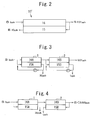
- Fig. 2 simply shows a water introducing channel into the desalting chamber and the concentrating chamber of the electrodeionization apparatus 10' of Fig. 1.
- raw water is introduced into the desalting chamber 16 to become product water.
- a part of the product water is introduced into the concentrating chamber 15, and is then drained as concentrated waste water.
- the direction of the water flow in the concentrating chamber is opposite (counter) to that in the desalting chambers 16.
- product water having a very low concentration of boron for example, 0.1 ppb or less
- product water having an extremely low concentration, 0.05 ppb or less, of boron by controlling boron content in the waste water to 500 times or less than that in the product water or to 10 ppb or less.
- Fig. 7a is a perspective view schematically showing another electrodeionization apparatus 10" according to another embodiment of the second aspect.
- Fig. 7b shows a water introducing channel of the apparatus.
- the electrodeionization apparatus 10" has a structure which is formed by alternately arranging cation-exchange membranes and anion-exchange membranes between an anode 11 and a cathode 12 so that a concentrating chamber 15 and desalting chambers 16 are alternately arranged, like the electrodeionization apparatus 10' shown in Fig. 1.
- the concentrating chamber 15 of the electrodeionization apparatus 10 " is divided into two or more concentrated water flowing sections 15a and 15b (two in Figs. 7a and 7b) by a partition 15S.
- the direction of the concentrated water flow in the concentrated water flowing sections 15a and 15b crosses the direction of the water flow in the desalting chambers 16, unlike the electrodeionization apparatus 10' shown in Fig. 1.
- the desalting chambers 16 have inlets at the top side and outlets at the bottom side, and water flows in the desalting chambers 16 from top to bottom in Fig. 7a.
- the partition 15S is provided in the concentrating chamber 15 so as to spread in a direction crossing the direction of the water flow in the desalting chambers 16 (two directions are orthogonal in Fig. 7a, but the term orthogonal direction should not been strictly interpreted here.
- the term orthogonal direction includes an angle range of about 80° to 100°.), and horizontally divides the inside of the concentrating chamber 15 into two stages in Fig. 7a. Water flows in each of the concentrated water flowing sections 15a and 15b from the front side to the rear side in Fig. 7a.
- a part of the product water discharged from the desalting chambers 16 is introduced into a circulatory system of the concentrated water flowing section 15b, and a pump circulates the product water in the concentrated water flowing section 15b disposed at a side of an outlet for the product water.
- a part of the circulating concentrated water of the circulatory system is introduced into a circulatory system of the concentrated water flowing section 15a, and a pump circulates the concentrated water in the concentrated water flowing section 15a disposed at a side of an inlet for raw water.
- a part of the circulating concentrated water of the circulatory system of the concentrated water flowing section 15a is drained out of the system.
- the product water circulates in the concentrated water flowing section 15b disposed at the side of the outlet for the product water, then enters the concentrated water flowing section 15a disposed at the side of the inlet for raw water and circulates in it, and is then drained out of the system.
- the concentrated water is introduced from the side of the outlet for the product water toward the inlet for raw water, and then a part of the concentrated water is drained out of the system. Therefore, the electrodeionization apparatus 10" also exhibits the effects similar to those in the case of introducing water into the desalting chambers in a single pass as shown in Fig. 1.
- the concentrating chamber may be divided by the partitions into three or more concentrated water flowing sections.
- the concentrating chamber is divided into two or three concentrated water flowing sections from the viewpoints of an increase in the number of members by increasing the number of the partitions and an increase in complexity of the apparatus composition.
- Figs. 3 to 6 show water introducing channels of electrodeionization systems provided with electrodeionization apparatuses in a multistage manner so that a first electrodeionization apparatus 1 and a second electrodeionization apparatus 2 are serially connected to each other.
- the apparatuses 1 and 2 may be either of the electrodeionization apparatus 10' or the electrodeionization apparatus 10 " .
- raw water having a boron concentration of 3 ppb is introduced into a desalting chamber 16A of the first electrodeionization apparatus 1, and becomes first product water having a boron concentration of 0.1 ppb.
- This first product water is introduced into both a desalting chamber 16B and a concentrating chamber 15B of the second electrodeionization apparatus 2.
- the direction of the concentrated water flow in concentrating chambers 15A and 15B is parallel to the direction of the flow in the desalting chambers 16A and 16B.
- Second product water (product water) having a boron concentration of 0.01 ppb is discharged from the desalting chamber 16B.
- Concentrated water discharged from the concentrating chamber 15B of the second electrodeionization apparatus 2 has a low boron concentration of 1 ppb. A part of the concentrated water is supplied to an inlet of the concentrating chamber 15B to be circulated, and the remaining part of the concentrated water is, for example, added to raw water.
- Concentrated waste water discharged from the concentrating chamber 15A of the first electrodeionization apparatus 1 has a high boron concentration of 30 ppb. A part of the concentrated waste water is sent to an inlet of the concentrating chamber 15A, and the remaining part of the concentrated water is drained as concentrated waste water.
- the raw water introduced into the concentrating chamber 15A of the first electrodeionization apparatus 1 flows in the parallel direction manner, and becomes first concentrated water having a boron concentration of 30 ppb to be drained.
- the raw water flows in the desalting chamber 16A and the desalting chamber 16B of the apparatus 1 in this order, and becomes second product water having a boron concentration of 0.005 ppb or less.
- the boron concentration of first product water discharged from the desalting chamber 16A is 0.05 ppb.
- a part of the second product water discharged from the desalting chamber 16B is introduced into the concentrating chamber 15B and then into the concentrating chamber 15A in the direction opposite to the flow in the desalting chambers, and then is drained as concentrated waste water with 15 ppb boron.
- the boron concentration of first concentrated water discharged from the concentrating chamber 15B is 0.25 ppb.
- the raw water is supplied to the desalting chamber 16A, and becomes first product water having a boron concentration of 0.02 ppb.
- a part of the first product water is introduced into the concentrating chamber 15A in the flow direction opposite to the flow in the desalting chamber, and is then drained as concentrated waste water with 30 ppb boron.
- the remaining first product water is introduced into the desalting chamber 16B and becomes second product water having a boron concentration of 0.005 ppb or less.
- a part of the second product water is introduced into the concentrating chamber 15B in the flow direction opposite to the flow in the desalting chamber, and then is discharged as second concentrated water with 0.2 ppb boron.
- the second concentrated water is, for example, added to raw water.
- the desalting chamber of the first electrodeionization apparatus 1 has a thickness of 7 mm or more, in particular, 8 to 30 mm
- the desalting chamber of the second electrodeionization apparatus 2 has a thickness of less than 7 mm, in particular, 2 to 5 mm
- weak electrolytes such as silica and boron, and high-hardness components are removed in the first electrodeionization apparatus 1, and silica and boron are further removed in the second electrodeionization apparatus 2. Since the second electrodeionization apparatus 2 removes alkaline materials that are leaked from the first electrodeionization apparatus 1 of the previous stage, the treated water having a high quality can be obtained.
- pH in the desalting chamber 16A of the apparatus 1 increases so that weak electrolytes, such as silica and boron, and high-hardness components are effectively removed.
- boron concentrations in the concentrating chambers disposed at the sides of outlets of the desalting chambers are decreased by supplying product water to the concentrating chambers.
- Boron-removed water may be supplied to the concentrating chambers, instead of the product water or in combination with the product water.
- Boron can be removed by either a method using ion-exchange resin or boron-adsorbing resin or a method using a reverse osmosis membrane.
- the electrodeionization apparatus and the method for operating the same according to the first and second aspects can surely produce product water having an extremely low concentration of boron.
- Fig. 8 is a schematic cross-sectional view of an electrodeionization apparatus 10 according to an embodiment of the third aspect of the present invention.
- the electrodeionization apparatus 10 is formed by alternately arranging a plurality of anion-exchange membranes (A-membrane) 13 and cation-exchange membranes (C-membrane) 14 between electrodes (anode 11 and cathode 12) so that concentrating chambers 15 and desalting chambers 16 are alternately arranged.
- the desalting chambers 16 are filled with a mixture or layers of an anion exchanger and a cation exchanger, such as ion-exchange resin, ion-exchange fibers, and graft exchanger.
- the concentrating chambers 15, an anode chamber 17, and a cathode chamber 18 are also filled with an electrically conductive material such as an ion exchanger, activated carbon, or metal.
- Water to be treated is introduced into the desalting chambers 16, and product water is discharged from the desalting chambers 16. A part of the water to be treated is sent to an anion-removing means 9, and anions in the water are removed.
- the water treated by the anion-removing means 9 is introduced into the concentrating chambers 15 in a single pass in the direction opposite to the flow in the desalting chambers 16, and is then drained out of a system from the concentrating chambers 15.
- the concentrating chambers 15 and the desalting chambers 16 are alternately arranged in parallel to each other.
- Inlets of the concentrating chambers 15 are provided at a side of outlets for discharging product water from the desalting chambers 16, and outlets of the concentrating chambers 15 are provided at a side of inlets for introducing raw water into the desalting chambers 16. Therefore, concentrated water is introduced into the concentrating chambers 15 from the side of the outlets of the desalting chambers (the under side in Fig. 8) and is discharged from the side of the inlets of the desalting chambers (the upper side in Fig. 8).
- a part of the water discharged from the anion-removing means 9 is supplied to an inlet of the anode chamber 17.
- the water discharged from the anode chamber 17 is supplied to an inlet of the cathode chamber 18.
- the water discharged from the cathode chamber 18 is drained out of the system as waste water.
- Water to be treated may be supplied to the inlet of the anode chamber 17 instead of the water discharged from the anion-removing means.
- the concentration of the concentrated water in the concentrating chambers 15 is the lowest at the side for discharging the product water.
- influences of concentration diffusion on the desalting chambers 16 are decreased.
- rates of removal of weak anions, such as carbonate, silica, and boron, in addition to strong anions can be greatly improved.
- the concentrating chamber is filled with a conductive material such as an ion exchanger. Therefore, it is unnecessary to decrease the electrical resistance of the concentrated water by adding an electrolyte such as sodium chloride.
- the electrode chambers 17 and 18 are also filled with an ion exchanger, activated carbon, or electrically conductive metal in order to ensure desired current. This makes it possible to ensure current necessary for introducing water with high quality, such as ultrapure deionized water.
- Oxidizing agents such as chlorine and ozone are generated in the electrode chambers, in particular, in the anode chamber. Therefore, activated carbon is better than ion-exchange resin as the filler on a long-term basis. It is desirable to supply the product water to the electrode chambers as shown in Fig. 8. Since the product water scarcely contains Cl - , no chlorine is generated and the filler and the electrodes are stable over a long period of time.
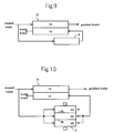
- Fig. 9 simply shows a water introducing channel into the desalting chamber and the concentrating chamber of the electrodeionization apparatus of Fig. 8.
- water to be treated is introduced into the desalting chamber 16 to become product water.
- a part of the water to be treated is treated for removing anions, and is then introduced into the concentrating chamber 15.
- the water introduced into the concentrating chamber 15 is then drained as concentrated waste water.
- the direction of the water flow in the concentrating chamber is opposite (counter) to that in the desalting chambers 16.
- the total inorganic carbonate concentration is controlled to 50 ppb or less, preferably, to 30 ppb or less. As a result, the total inorganic carbonate concentration in the product water is extremely decreased. Furthermore, with the anion-removing means 9, silica concentration is controlled to 100 ppb or less, preferably, to 80 ppb or less, and boron concentration is controlled to 10 ppb or less, preferably, to 8 ppb or less. As a result, the silica concentration and the boron concentration in the product water are extremely decreased.
- anion-removing means 9 examples include degassers such as degassing membranes, decarbonation columns, and vacuum degassing columns; reverse osmosis membrane separation units; electrodialysers; ion-exchange units such as ion-exchange resin columns including anion exchangers; and electrodeionization units.
- degassing means such as a degassing membrane, a decarbonation column, or a vacuum degassing column.
- a degassing-membrane unit for performing a vacuum suction for example, 20 Torr or more
- a sweeping with nitrogen, or a combination thereof is superior in efficiency of removing carbonate.
- Fig. 10 shows an example of a channel when an electrodeionization unit 8 is used as the anion-removing means 9.
- the electrodeionization unit 8 is formed by arranging an anion membrane 8a and a cation membrane 8c between an anode and a cathode so that a desalting chamber 8D and concentrating chambers 8A and 8B are formed. Water to be treated is introduced into chambers 8A, 8B, and 8D to flow parallel to each other. Desalted water from the desalting chamber 8D and concentrated water from the concentrating chamber 8B are supplied to the concentrating water 15 of the electrodeionization apparatus 10 at a side of an outlet of the desalting chamber, and are then discharged from a side of an inlet of the desalting chamber.
- the electrodeionization unit 8 is provided with the concentrating chamber 8A disposed at a side of the anion membrane 8a of the desalting chamber 8D and the concentrating chamber 8B disposed at a side of cation membrane 8c. Only concentrated anion components are discharged into the concentrating chamber 8A, and concentrated cations from the concentrating chamber 8B and desalted water from the desalting chamber 8D are supplied to the concentrating chamber 15 of the electrodeionization apparatus 10. In such a manner, the electrodeionization unit 8 removes and decreases anion components only.
- anion-removed water may be supplied to the desalting chamber as the water to be treated.
- anion load on the desalting chamber is decreased, the weak anion concentration in the product water can be further decreased.
- Degassing treatment and reverse osmosis treatment are preferable for removing these anions.
- Adsorptive removal of organic components by activated carbon and ionization of chlorine are also preferable.
- a degassing means (in particular, a membrane degassing unit) is most preferably used as a means for removing anions.
- a part of the degassed water is preferably recirculated from the inlet of the degassing unit so that the efficiency of removing carbonate is increased.
- the efficiency of removing carbonate is desirably increased by controlling the introduced water to be acidic, preferably, to have a pH of 4 to 6, more preferably, a pH of 4 to 5.
- RO treatment reverse osmosis treatment
- the weak anion components such as carbonate, silica, and boron
- the efficiency of removing the weak anion components is improved by using alkaline water (a pH of 8 to 10) to the RO of a first and/or a second stage.
- the alkalinity may be produced by using an electrodeionization unit including a desalting chamber having a thickness of 7 mm or more (preferably 15 mm) and being filled with an ion exchanger of a mixture of anions and cations, as disclosed in Japanese Unexamined Patent Application Publication No. 2001-113281. This can not only produce the alkalinity, but also reduce the weak anion components.
- Such electrodeionization unit is desirably disposed between the RO units of the first and the second stages.
- the pretreatment including the two-stage RO treatment and degassing treatment is particularly preferable to obtain ultrapure water of extremely high purity, for example, treated water having a specific resistance of 18.2 M ⁇ cm or more, a silica concentration of 0.05 ppb or less, and a boron concentration of 0.005 ppb or less.
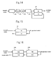
- Figs. 4 to 7 show configuration examples in which the above-mentioned pretreatment unit is located anterior to the electrodeionization apparatus 10.
- raw water is degassed by a degassing membrane unit 101 as a pretreatment unit, and is then sent to the electrodeionization apparatus 10 as the water to be treated.
- a part of the water treated by the degassing membrane unit 101 is resent to the upstream side of the unit 101 and is repeatedly treated.
- raw water is introduced to pretreatment, i.e. into an activated carbon adsorption column 102 and two-stage RO units 103, and is then used as the water to be treated.
- raw water is treated with an activated carbon adsorption column 102, a first RO unit 103, an electrodeionization unit 104, and a second RO unit 103; and is sent to the electrodeionization apparatus 10 as the water to be treated.
- the electrodeionization unit 104 may be an electrodeionization apparatus, for example, disclosed in Japanese Unexamined Patent Application Publication No. 2001-113281, but is not limited to.
- raw water is treated with an activated carbon adsorption column 102, two-stage RO units 103, and a degassing membrane unit 101; and is then sent to the electrodeionization apparatus 10 as the water to be treated.
- the means for removing anions from concentrated water supplied to the concentrating chamber may be the electrodeionization apparatus 10 itself. Namely, as shown in Fig. 15, all the water to be treated may be introduced into the desalting chamber 16 of the electrodeionization apparatus 10, and a part of product water may be introduced into the concentrating chambers 15 from a side of the outlet of the desalting chamber toward a side of the inlet of the desalting chamber.
- the electrodeionization apparatuses 10 may be installed in a multistage manner, and raw water may be deionized in a multistage manner.
- Fig. 16 is a water introducing channel of an electrodeionization system including electrodeionization apparatuses 10A and 10B having the same structure as that of the electrodeionization apparatus 10 in a multistage manner.
- the first electrodeionization apparatus 10A and the second electrodeionization apparatus 10B are serially connected to each other.
- water to be treated is introduced into a desalting chamber 16 of the first electrodeionization apparatus 10A to become first product water.
- This first product water is introduced into a desalting chamber 16B of the second electrodeionization apparatus 10B.
- the flow direction of concentrated water in concentrating chambers 15A and 15B is opposite to the flow direction in the desalting chambers 16A and 16B.
- Second product water (product water) is discharged from the desalting chamber 16B, and a part of the second product water is supplied to the concentrating chamber 15B.
- the concentrated water discharged from the concentrating chamber 15B of the second electrodeionization apparatus 2 has a low anion concentration, and is supplied to the concentrating chamber 15A.
- Water discharged from the concentrating chamber 15A of the first electrodeionization apparatus 1 is drained as concentrated waste water.
- the desalting chamber has a thickness of 2 to 7 mm, and a flow velocity is 60 to 120 m/h in the terms of LV and 100 to 200 /h in the terms of SV.
- the concentrating chamber has a thickness of 2 to 7 mm, and a flow velocity is 10 to 30 m/h in the terms of LV and 25 to 50 /h in the terms of SV.
- both the desalting chamber and the concentrating chamber are filled with an ion exchanger, in particular, with a mixture of anions and cations; and are operated at a current density of 300 to 700 mA/dm 2 . Water supplied to the concentrating chamber is not recirculated to the inlet of the concentrating chamber with a circulation pump, but the concentrating chamber desirably runs with the water in a single pass.
- the desalting chamber at the last stage preferably has a thickness of 2 to 7 mm, and a flow velocity is preferably 60 to 120 m/h in the terms of LV and 100 to 200 /h in the terms of SV.
- the electrodeionization apparatus and the method for operating the apparatus according to the present invention can surely produce product water having extremely low concentrations of anions, in particular, of total inorganic carbonate.
Landscapes
- Engineering & Computer Science (AREA)
- Water Supply & Treatment (AREA)
- Chemical & Material Sciences (AREA)
- Chemical Kinetics & Catalysis (AREA)
- Health & Medical Sciences (AREA)
- Urology & Nephrology (AREA)
- Life Sciences & Earth Sciences (AREA)
- Environmental & Geological Engineering (AREA)
- Hydrology & Water Resources (AREA)
- Organic Chemistry (AREA)
- Analytical Chemistry (AREA)
- Molecular Biology (AREA)
- Electrochemistry (AREA)
- General Chemical & Material Sciences (AREA)
- Water Treatment By Electricity Or Magnetism (AREA)
- Separation Using Semi-Permeable Membranes (AREA)
Abstract
An electrodeionization apparatus and a method for
operating the apparatus are provided. With this,
concentration diffusion of boron from a concentrating
chamber can be suppressed to obtain product water having a
very low boron concentration. Raw water in introduced into
a desalting chamber 16, and product water is discharged from
the desalting chamber 16. A part of the product water is
introduced into a concentrating chamber 15 in a single pass
in the direction opposite to the flow in the desalting
chamber 16. Water discharged from the concentrating chamber
15 is drained out of a system. An inlet of the
concentrating chamber 15 is provided at a side of an outlet
for discharging product water from the desalting chamber 16,
and an outlet of the concentrating chamber 15 is provided at
a side of an inlet for introducing raw water into the
desalting chamber 16. Concentrated water discharged from
the concentrating chamber has a boron concentration of 500
times or less than that of the product water or of 10 ppb or
less.
Description
The present invention relates to an electrodeionization
apparatus for producing product water having a very low
concentration of boron or for producing product water having
a very low concentration of anions, and also relates to a
method for operating the apparatus.
Electrodeionization apparatuses are used in the field
where deionized water and ultrapure deionized water are
produced. A plate-and-frame type electrodeionization
apparatus has an anode, a cathode, anion-exchange membranes,
and cation-exchange membranes. The membranes are
alternately arranged in such a manner as to alternately form
concentrating chambers and desalting chambers (diluting
chambers) between the anode and the cathode. The desalting
chambers are filled with an ion exchanger such as ion-exchange
resin. Water to be desalted flows through the
desalting chambers, and ions in the water pass through the
ion-exchange membranes to move from the desalting chambers
to the concentrating chambers.
Japanese Unexamined Patent Application Publication No.
2002-205069 discloses a method for producing product water
having very low concentrations of silica and boron. The
product water is produced by introducing water containing
silica or boron at a concentration lower than that of raw
water into concentrating chambers at a side near outlets for
discharging deionized water from desalting chambers,
discharging concentrated water from the concentrating
chambers at a side near inlets for introducing the raw water
into the desalting chambers, and draining at least a part of
the concentrated water discharged from the concentrating
chambers out of a system.
In the patent document, product water of high quality
can be obtained by using the concentrated water containing
silica or boron at a concentration lower than that of the
raw water and letting such water of good quality flow in the
concentrating chambers from the side of the outlets for
discharging the deionized water (product water) from the
desalting chambers toward the side of the inlets for
introducing the raw water into the desalting chambers. The
silica or boron concentration of the resulting product water
is significantly decreased.
It is an object of the present invention to provide an
electrodeionization apparatus and a method for operating an
electrodeionization apparatus which can obtain product water
having a very low concentration of boron by sufficiently
controlling the concentration diffusion of boron from a
concentrating chamber. It is also an object of the present
invention to provide an electrodeionization apparatus and a
method for operating an electrodeionization apparatus which
can obtain product water having a very low concentration of
carbonate by sufficiently controlling the concentration
diffusion of anions such as carbonate ions from the
concentrating chamber.
A method according to a first aspect of the present
invention is for operating an electrodeionization apparatus
which has at least one concentrating chamber and at least
one desalting chamber isolated by ion-exchange membranes
between an anode and a cathode. Concentrated water is
introduced into the concentrating chamber. Raw water is
introduced into the desalting chamber as water to be treated
and is discharged as product water. The concentrated water
discharged from the concentrating chamber has a boron
concentration of 500 times or less than that in the product
water or of 10 ppb or less.
An electrodeionization apparatus according a second
aspect of the present invention has at least one
concentrating chamber and at least one desalting chamber
isolated by ion-exchange membranes between an anode and a
cathode. Concentrated water is introduced into the
concentrating chamber, and raw water is introduced into the
desalting chamber as water to be treated and is discharged
as product water. The concentrated water discharged from
the concentrating chamber has a boron concentration of 500
times or less than that in the product water or of 10 ppb or
less.
In the first and the second aspects, a boron
concentration of the concentrated water discharged from the
concentrating chamber is reduced in order to produce product
water of high purity, having a very low boron concentration,
for example, 0.1 ppb or less.
When a plurality of the desalting chambers and the
concentrating chambers are provided along a flow direction
of water to be treated, concentrated water discharged from
the concentrating chamber of the downstreammost preferably
has a boron concentration of 500 times or less than that in
product water discharged from the desalting chamber of the
downstreammost or of 10 ppb or less. With this, the boron
concentration gradient from the concentrating chamber toward
the desalting chamber at around the outlet of the
concentrating chamber is also relatively reduced. Therefore,
boron diffusion from the concentrating chamber to the
desalting chamber can be controlled to reduce the boron
concentration in the product water.
In the first and the second aspects, raw water
introduced into the electrodeionization apparatus is
preferably pretreated. In particular, it is desirable to
perform an RO treatment after the removal of turbidity of
raw water such as tap water by an MF membrane and the
desalting by activated carbon. Furthermore, degassing
treatment may be performed.
In particular, when a boron concentration of product
water is 0.005 ppb or less, two-stage reverse osmosis (RO)
is further desirably performed in order to reduce the load
of feeding on the electrodeionization apparatus (for example,
to 3 ppb or less).
The desalting chamber may be filled with an ion
exchanger.
The electrical resistance of the concentrating chamber
is increased by introducing water of high quality, having a
low electrical conductivity and a high specific resistance,
into the concentrating chamber. As a result, there is a
possibility not to ensure a desirable current value.
Therefore, the concentrating chamber may be also filled with
an ion exchanger such as ion-exchange resin, activated
carbon, or other electrically conductive material to ensure
necessary current.
In a method for operating an electrodeionization
apparatus according to a third aspect of the present
invention, water to be treated is introduced into the
desalting chamber, and concentrated water is introduced into
the concentrating chamber. The concentrated water to be fed
into the concentrating chamber is treated by an anion
removing means to remove anions therefrom so as to have a
low concentration of anions. The concentrated water is
introduced into the concentrating chamber from a side near
an outlet of the desalting chamber and is discharged from a
side near an inlet of the desalting chamber.
An electrodeionization apparatus according to a fourth
aspect of the present invention has at least one
concentrating chamber and at least one desalting chamber
isolated by ion-exchange membranes between an anode and a
cathode. Water to be treated is introduced into the
desalting chamber, and concentrated water is introduced into
the concentrating chamber. The electrodeionization
apparatus is provided with means for introducing and
discharging the concentrated water so that the concentrated
water is introduced into the concentrating chamber from a
side near an outlet of the desalting chamber and is
discharged from the concentrating chamber from a side near
an inlet of the desalting chamber. Furthermore, the
electrodeionization apparatus is provided with a means for
removing anions from the concentrated water that is
introduced into the concentrating chamber.
In the third and fourth aspects, the concentrated water
supplied to the concentrating chamber has low concentrations
of anions such as carbonate in order to produce product
water of high purity, having an extremely low concentration
of anions such as carbonate.
With this, the anion concentration gradient from the
concentrating chamber toward the desalting chamber at around
the outlet of the concentrating chamber is also relatively
reduced. Therefore, carbonate diffusion from the
concentrating chamber to the desalting chamber is controlled
to reduce a carbonate concentration in product water.
In the third and fourth aspects, diffusion caused by
the carbonate ion concentration gradient from the
concentrating chamber toward the desalting chamber is
suppressed by controlling the total inorganic carbonate
concentration of the concentrated water introduced into the
concentrating chamber to 50 ppb or less. Thus, the
production of product water having an extremely low total
inorganic carbonate concentration can be possible.
In the third and fourth aspects, similarly, diffusion
caused by the ion concentration gradient from the
concentrating chamber toward the desalting chamber is
suppressed by controlling the silica concentration and boron
concentration of the concentrated water introduced into the
concentrating chamber to 100 ppb or less and 10 ppb or less,
respectively. Thus, the production of product water having
extremely low silica and boron concentrations can be
possible.
A part of the product water that is discharged from the
desalting chamber may be used as the concentrated water in
order to decrease the total inorganic carbonate
concentration, silica concentration, and boron concentration
in the concentrated water that is introduced into the
concentrated water. Furthermore, water to be supplied to
the concentrating chamber may be treated by an ion-exchange
unit and an electrodeionization unit.
A degassing means such as a degassing membrane unit may
be used for decreasing the total inorganic carbonate
concentration in the concentrated water that is introduced
into the concentrating chamber.
In the third and fourth aspects, raw water may be
introduced into the desalting chamber after the treatment
for removing anions. The anion concentration in the product
water can be further decreased. Reverse osmosis and
degassing are preferable as the treatment for removing
anions. Multistage reverse osmosis and the subsequent
degassing are more preferable.
Preferred embodiments of the invention will now be
described in detail with reference to the accompanying
drawings.
Fig. 1 is a schematic cross-sectional view of an
electrodeionization apparatus 10' showing an example
according to first and second aspects. The
electrodeionization apparatus is formed by alternately
arranging a plurality of anion-exchange membranes (A-membrane)
13 and cation-exchange membranes (C-membrane) 14
between electrodes (anode 11 and cathode 12) so that
concentrating chambers 15 and desalting chambers 16 are
alternately arranged. The desalting chambers 16 are filled
with a mixture or layers of an anion exchanger and a cation
exchanger, such as ion-exchange resin, ion-exchange fibers,
and graft exchanger.
The concentrating chambers 15, an anode chamber 17, and
cathode chamber 18 are also filled with an electrically
conductive material such as an ion exchanger, activated
carbon, or metal.
Raw water is introduced into the desalting chambers 16,
and product water is discharged from the desalting chambers
16. A part of the product water is introduced to the
concentrating chambers 15 in a single pass in the direction
opposite to the flow in the desalting chambers 16, and is
drained out of a system from the concentrating chambers 15.
Namely, in the electrodeionization apparatus, the
concentrating chambers 15 and the desalting chambers 16 are
alternately arranged, inlets of the concentrating chambers
15 are disposed at the side where the product water is
discharged from the desalting chambers 16, and outlets of
the concentrating chambers 15 are disposed at the side where
raw water is introduced into the desalting chambers 16. A
part of the product water is supplied to an inlet of the
anode chamber 17. The water discharged from the anode
chamber 17 is supplied to an inlet of the cathode chamber 18.
Then, the water is discharged out of the system as waste
water from the cathode chamber 18.
As described above, by introducing the product water
into the concentrating chambers 15 in a single pass in the
direction opposite to the flow in the desalting chambers 16,
the concentration of the concentrated water in the
concentrating chambers 15 is the lowest at the side of
outlets for discharging the product water to decrease
influences of concentration diffusion on the desalting
chambers 16; thus, a rate of removal of ions such as boron
is greatly improved.
In this embodiment, since the electrical resistance of
the electrodeionization apparatus is increased by
introducing the product water into the concentrating
chambers, the concentrating chambers are also filled with a
conductive material such as an ion exchanger. Therefore, it
is unnecessary to decrease the electrical resistance by
adding an electrolyte such as sodium chloride to the
concentrated water.
In the electrodeionization apparatus 10' shown in Fig.
1, the product water is introduced into the electrodes
chambers 17 and 18 too. Preferably, the electrode chambers
17 and 18 are also filled with an ion exchanger, activated
carbon, or electrically conductive metal in order to ensure
desired current as in the concentrating chambers 15. This
makes it possible to ensure current necessary for
introducing water of high quality such as ultrapure
deionized water.
Oxidizing agents such as chlorine and ozone are
generated in the electrode chambers, in particular, in the
anode chamber. Therefore, activated carbon is better than
ion-exchange resin as the filler on a long-term base. It is
desirable to supply the product water containing
substantially no Cl- to the electrode chambers as shown in
Fig. 1 in order to avoid occurrence of chlorine and to
stabilize the filler and the electrodes.
Fig. 2 simply shows a water introducing channel into
the desalting chamber and the concentrating chamber of the
electrodeionization apparatus 10' of Fig. 1. As shown in
the drawing, raw water is introduced into the desalting
chamber 16 to become product water. A part of the product
water is introduced into the concentrating chamber 15, and
is then drained as concentrated waste water. The direction
of the water flow in the concentrating chamber is opposite
(counter) to that in the desalting chambers 16.
It is possible to produce product water having a very
low concentration of boron, for example, 0.1 ppb or less,
and is further possible to produce product water having an
extremely low concentration, 0.05 ppb or less, of boron by
controlling boron content in the waste water to 500 times or
less than that in the product water or to 10 ppb or less.
Fig. 7a is a perspective view schematically showing
another electrodeionization apparatus 10" according to
another embodiment of the second aspect. Fig. 7b shows a
water introducing channel of the apparatus.
As shown in the drawing, the electrodeionization
apparatus 10" has a structure which is formed by
alternately arranging cation-exchange membranes and anion-exchange
membranes between an anode 11 and a cathode 12 so
that a concentrating chamber 15 and desalting chambers 16
are alternately arranged, like the electrodeionization
apparatus 10' shown in Fig. 1. However, the concentrating
chamber 15 of the electrodeionization apparatus 10 " is
divided into two or more concentrated water flowing sections
15a and 15b (two in Figs. 7a and 7b) by a partition 15S.
The direction of the concentrated water flow in the
concentrated water flowing sections 15a and 15b crosses the
direction of the water flow in the desalting chambers 16,
unlike the electrodeionization apparatus 10' shown in Fig. 1.
Namely, in Figs. 7a and 7b, the desalting chambers 16
have inlets at the top side and outlets at the bottom side,
and water flows in the desalting chambers 16 from top to
bottom in Fig. 7a.
The partition 15S is provided in the concentrating
chamber 15 so as to spread in a direction crossing the
direction of the water flow in the desalting chambers 16
(two directions are orthogonal in Fig. 7a, but the term
orthogonal direction should not been strictly interpreted
here. The term orthogonal direction includes an angle range
of about 80° to 100°.), and horizontally divides the inside
of the concentrating chamber 15 into two stages in Fig. 7a.
Water flows in each of the concentrated water flowing
sections 15a and 15b from the front side to the rear side in
Fig. 7a.
As shown in Fig. 7b, a part of the product water
discharged from the desalting chambers 16 is introduced into
a circulatory system of the concentrated water flowing
section 15b, and a pump circulates the product water in the
concentrated water flowing section 15b disposed at a side of
an outlet for the product water. A part of the circulating
concentrated water of the circulatory system is introduced
into a circulatory system of the concentrated water flowing
section 15a, and a pump circulates the concentrated water in
the concentrated water flowing section 15a disposed at a
side of an inlet for raw water. A part of the circulating
concentrated water of the circulatory system of the
concentrated water flowing section 15a is drained out of the
system.
In the electrodeionization apparatus 10 " , the product
water circulates in the concentrated water flowing section
15b disposed at the side of the outlet for the product water,
then enters the concentrated water flowing section 15a
disposed at the side of the inlet for raw water and
circulates in it, and is then drained out of the system. As
a result, the concentrated water is introduced from the side
of the outlet for the product water toward the inlet for raw
water, and then a part of the concentrated water is drained
out of the system. Therefore, the electrodeionization
apparatus 10" also exhibits the effects similar to those in
the case of introducing water into the desalting chambers in
a single pass as shown in Fig. 1.
The concentrating chamber may be divided by the
partitions into three or more concentrated water flowing
sections. Preferably, the concentrating chamber is divided
into two or three concentrated water flowing sections from
the viewpoints of an increase in the number of members by
increasing the number of the partitions and an increase in
complexity of the apparatus composition.
In the electrodeionization apparatus 10" as shown in
Figs. 7a and 7b, it is also possible to produce product
water having a very low concentration of boron, for example,
0.1 ppb or less, and is further possible to produce product
water having an extremely low concentration of boron, 0.05
ppb or less, by controlling boron content in the
concentrated waste water drained from the concentrated water
flowing section 15b to 500 times or less than that in the
product water or to 10 ppb or less.
It is possible to surely produce product water having a
very low concentration of boron such as the above, and
further possible to produce product water at an ultra-low
concentration of 0.005 ppb or less by deionizing raw water
in a multistage manner with the electrodeionization
apparatuses installed in a multistage manner.
Figs. 3 to 6 show water introducing channels of
electrodeionization systems provided with
electrodeionization apparatuses in a multistage manner so
that a first electrodeionization apparatus 1 and a second
electrodeionization apparatus 2 are serially connected to
each other. The apparatuses 1 and 2 may be either of the
electrodeionization apparatus 10' or the electrodeionization
apparatus 10 " .
In the electrodeionization system shown in Fig. 3, raw
water having a boron concentration of 3 ppb is introduced
into a desalting chamber 16A of the first
electrodeionization apparatus 1, and becomes first product
water having a boron concentration of 0.1 ppb. This first
product water is introduced into both a desalting chamber
16B and a concentrating chamber 15B of the second
electrodeionization apparatus 2. The direction of the
concentrated water flow in concentrating chambers 15A and
15B is parallel to the direction of the flow in the
desalting chambers 16A and 16B. Second product water
(product water) having a boron concentration of 0.01 ppb is
discharged from the desalting chamber 16B. Concentrated
water discharged from the concentrating chamber 15B of the
second electrodeionization apparatus 2 has a low boron
concentration of 1 ppb. A part of the concentrated water is
supplied to an inlet of the concentrating chamber 15B to be
circulated, and the remaining part of the concentrated water
is, for example, added to raw water.
Concentrated waste water discharged from the
concentrating chamber 15A of the first electrodeionization
apparatus 1 has a high boron concentration of 30 ppb. A
part of the concentrated waste water is sent to an inlet of
the concentrating chamber 15A, and the remaining part of the
concentrated water is drained as concentrated waste water.
In the electrodeionization system shown in Fig. 4, all
the first product water having a boron concentration of 0.1
ppb is introduced into the desalting chamber 16B of the
second electrodeionization apparatus 2 from the desalting
chamber 16A of the first electrodeionization apparatus 1,
and becomes second product water having a boron
concentration of 0.005 ppb or less. A part of the second
product water is introduced into the concentrating chamber
15B to flow in the opposite direction manner. Second
concentrated water having a boron concentration of 1 ppb is
discharged from the concentrating chamber 15B and is, for
example, added to raw water.
The raw water introduced into the concentrating chamber
15A of the first electrodeionization apparatus 1 flows in
the parallel direction manner, and becomes first
concentrated water having a boron concentration of 30 ppb to
be drained.
In the electrodeionization system shown in Fig. 5, all
the raw water flows in the desalting chamber 16A and the
desalting chamber 16B of the apparatus 1 in this order, and
becomes second product water having a boron concentration of
0.005 ppb or less. The boron concentration of first product
water discharged from the desalting chamber 16A is 0.05 ppb.
A part of the second product water discharged from the
desalting chamber 16B is introduced into the concentrating
chamber 15B and then into the concentrating chamber 15A in
the direction opposite to the flow in the desalting chambers,
and then is drained as concentrated waste water with 15 ppb
boron. The boron concentration of first concentrated water
discharged from the concentrating chamber 15B is 0.25 ppb.
In the electrodeionization system shown in Fig. 6, all
the raw water is supplied to the desalting chamber 16A, and
becomes first product water having a boron concentration of
0.02 ppb. A part of the first product water is introduced
into the concentrating chamber 15A in the flow direction
opposite to the flow in the desalting chamber, and is then
drained as concentrated waste water with 30 ppb boron. The
remaining first product water is introduced into the
desalting chamber 16B and becomes second product water
having a boron concentration of 0.005 ppb or less. A part
of the second product water is introduced into the
concentrating chamber 15B in the flow direction opposite to
the flow in the desalting chamber, and then is discharged as
second concentrated water with 0.2 ppb boron. The second
concentrated water is, for example, added to raw water.
With reference to Figs. 3 to 6, in the
electrodeionization apparatuses installed in a multistage
manner, when the desalting chamber of the first
electrodeionization apparatus 1 has a thickness of 7 mm or
more, in particular, 8 to 30 mm, and the desalting chamber
of the second electrodeionization apparatus 2 has a
thickness of less than 7 mm, in particular, 2 to 5 mm; weak
electrolytes, such as silica and boron, and high-hardness
components are removed in the first electrodeionization
apparatus 1, and silica and boron are further removed in the
second electrodeionization apparatus 2. Since the second
electrodeionization apparatus 2 removes alkaline materials
that are leaked from the first electrodeionization apparatus
1 of the previous stage, the treated water having a high
quality can be obtained.
When the desalting chamber of the first
electrodeionization apparatus 1 has a thickness of 7 mm or
more, pH in the desalting chamber 16A of the apparatus 1
increases so that weak electrolytes, such as silica and
boron, and high-hardness components are effectively removed.
In the above-mentioned embodiments, boron
concentrations in the concentrating chambers disposed at the
sides of outlets of the desalting chambers are decreased by
supplying product water to the concentrating chambers.
Boron-removed water may be supplied to the concentrating
chambers, instead of the product water or in combination
with the product water.
Boron can be removed by either a method using ion-exchange
resin or boron-adsorbing resin or a method using a
reverse osmosis membrane.
As described above, the electrodeionization apparatus
and the method for operating the same according to the first
and second aspects can surely produce product water having
an extremely low concentration of boron.
Fig. 8 is a schematic cross-sectional view of an
electrodeionization apparatus 10 according to an embodiment
of the third aspect of the present invention. The
electrodeionization apparatus 10 is formed by alternately
arranging a plurality of anion-exchange membranes (A-membrane)
13 and cation-exchange membranes (C-membrane) 14
between electrodes (anode 11 and cathode 12) so that
concentrating chambers 15 and desalting chambers 16 are
alternately arranged. The desalting chambers 16 are filled
with a mixture or layers of an anion exchanger and a cation
exchanger, such as ion-exchange resin, ion-exchange fibers,
and graft exchanger.
The concentrating chambers 15, an anode chamber 17, and
a cathode chamber 18 are also filled with an electrically
conductive material such as an ion exchanger, activated
carbon, or metal.
Water to be treated is introduced into the desalting
chambers 16, and product water is discharged from the
desalting chambers 16. A part of the water to be treated is
sent to an anion-removing means 9, and anions in the water
are removed. The water treated by the anion-removing means
9 is introduced into the concentrating chambers 15 in a
single pass in the direction opposite to the flow in the
desalting chambers 16, and is then drained out of a system
from the concentrating chambers 15. In this
electrodeionization apparatus, the concentrating chambers 15
and the desalting chambers 16 are alternately arranged in
parallel to each other. Inlets of the concentrating
chambers 15 are provided at a side of outlets for
discharging product water from the desalting chambers 16,
and outlets of the concentrating chambers 15 are provided at
a side of inlets for introducing raw water into the
desalting chambers 16. Therefore, concentrated water is
introduced into the concentrating chambers 15 from the side
of the outlets of the desalting chambers (the under side in
Fig. 8) and is discharged from the side of the inlets of the
desalting chambers (the upper side in Fig. 8).
A part of the water discharged from the anion-removing
means 9 is supplied to an inlet of the anode chamber 17.
The water discharged from the anode chamber 17 is supplied
to an inlet of the cathode chamber 18. Then, the water
discharged from the cathode chamber 18 is drained out of the
system as waste water. Water to be treated may be supplied
to the inlet of the anode chamber 17 instead of the water
discharged from the anion-removing means.
As described above, by introducing the water treated by
the anion-removing means into the concentrating chambers 15
in a single pass in the direction opposite to the flow in
the desalting chambers 16, the concentration of the
concentrated water in the concentrating chambers 15 is the
lowest at the side for discharging the product water. As a
result, influences of concentration diffusion on the
desalting chambers 16 are decreased. Thus, rates of removal
of weak anions, such as carbonate, silica, and boron, in
addition to strong anions can be greatly improved. With
this electrodeionization apparatus, product water having a
resistivity of 18 MΩ·cm or more can be produced.
When the electrical conductivity of water introduced
into the concentrating chamber is low by the anion-removing
treatment and the electrical resistance of the
electrodeionization apparatus is high, the concentrating
chamber is filled with a conductive material such as an ion
exchanger. Therefore, it is unnecessary to decrease the
electrical resistance of the concentrated water by adding an
electrolyte such as sodium chloride. Preferably, the
electrode chambers 17 and 18 are also filled with an ion
exchanger, activated carbon, or electrically conductive
metal in order to ensure desired current. This makes it
possible to ensure current necessary for introducing water
with high quality, such as ultrapure deionized water.
Oxidizing agents such as chlorine and ozone are
generated in the electrode chambers, in particular, in the
anode chamber. Therefore, activated carbon is better than
ion-exchange resin as the filler on a long-term basis. It
is desirable to supply the product water to the electrode
chambers as shown in Fig. 8. Since the product water
scarcely contains Cl-, no chlorine is generated and the
filler and the electrodes are stable over a long period of
time.
Fig. 9 simply shows a water introducing channel into
the desalting chamber and the concentrating chamber of the
electrodeionization apparatus of Fig. 8. As shown in the
drawing, water to be treated is introduced into the
desalting chamber 16 to become product water. A part of the
water to be treated is treated for removing anions, and is
then introduced into the concentrating chamber 15. The
water introduced into the concentrating chamber 15 is then
drained as concentrated waste water. The direction of the
water flow in the concentrating chamber is opposite
(counter) to that in the desalting chambers 16.
With the anion-removing means 9, the total inorganic
carbonate concentration is controlled to 50 ppb or less,
preferably, to 30 ppb or less. As a result, the total
inorganic carbonate concentration in the product water is
extremely decreased. Furthermore, with the anion-removing
means 9, silica concentration is controlled to 100 ppb or
less, preferably, to 80 ppb or less, and boron concentration
is controlled to 10 ppb or less, preferably, to 8 ppb or
less. As a result, the silica concentration and the boron
concentration in the product water are extremely decreased.
Examples of the anion-removing means 9 include
degassers such as degassing membranes, decarbonation columns,
and vacuum degassing columns; reverse osmosis membrane
separation units; electrodialysers; ion-exchange units such
as ion-exchange resin columns including anion exchangers;
and electrodeionization units.
It is desirable for removing carbonate to include
degassing means such as a degassing membrane, a
decarbonation column, or a vacuum degassing column. In
particular, a degassing-membrane unit for performing a
vacuum suction (for example, 20 Torr or more), a sweeping
with nitrogen, or a combination thereof is superior in
efficiency of removing carbonate.
Fig. 10 shows an example of a channel when an
electrodeionization unit 8 is used as the anion-removing
means 9. The electrodeionization unit 8 is formed by
arranging an anion membrane 8a and a cation membrane 8c
between an anode and a cathode so that a desalting chamber
8D and concentrating chambers 8A and 8B are formed. Water
to be treated is introduced into chambers 8A, 8B, and 8D to
flow parallel to each other. Desalted water from the
desalting chamber 8D and concentrated water from the
concentrating chamber 8B are supplied to the concentrating
water 15 of the electrodeionization apparatus 10 at a side
of an outlet of the desalting chamber, and are then
discharged from a side of an inlet of the desalting chamber.
The electrodeionization unit 8 is provided with the
concentrating chamber 8A disposed at a side of the anion
membrane 8a of the desalting chamber 8D and the
concentrating chamber 8B disposed at a side of cation
membrane 8c. Only concentrated anion components are
discharged into the concentrating chamber 8A, and
concentrated cations from the concentrating chamber 8B and
desalted water from the desalting chamber 8D are supplied to
the concentrating chamber 15 of the electrodeionization
apparatus 10. In such a manner, the electrodeionization
unit 8 removes and decreases anion components only.
In the present invention, anion-removed water may be
supplied to the desalting chamber as the water to be treated.
With this, since anion load on the desalting chamber is
decreased, the weak anion concentration in the product water
can be further decreased. Degassing treatment and reverse
osmosis treatment are preferable for removing these anions.
Adsorptive removal of organic components by activated carbon
and ionization of chlorine are also preferable.
When carbonate ions are removed from the water to be
introduced into the desalting chamber by anion-removing
treatment, a degassing means (in particular, a membrane
degassing unit) is most preferably used as a means for
removing anions. A part of the degassed water is preferably
recirculated from the inlet of the degassing unit so that
the efficiency of removing carbonate is increased.
In the degassing treatment for removing carbonate, the
efficiency of removing carbonate is desirably increased by
controlling the introduced water to be acidic, preferably,
to have a pH of 4 to 6, more preferably, a pH of 4 to 5.
In the aspiration of gas with a vacuum pump through a
degassing membrane, it is desirable to control the degree of
vacuum at 50 Torr or less, more preferably, 20 Torr or less
to increase the efficiency of removing carbonate.
In the reverse osmosis treatment (RO treatment) of raw
water, it is desirable to sufficiently decrease the weak
anion components such as carbonate, silica, and boron by
conducting multistage treatment, for example, two-stage
treatment.
In this case, the efficiency of removing the weak anion
components is improved by using alkaline water (a pH of 8 to
10) to the RO of a first and/or a second stage.
The alkalinity may be produced by using an
electrodeionization unit including a desalting chamber
having a thickness of 7 mm or more (preferably 15 mm) and
being filled with an ion exchanger of a mixture of anions
and cations, as disclosed in Japanese Unexamined Patent
Application Publication No. 2001-113281. This can not only
produce the alkalinity, but also reduce the weak anion
components. Such electrodeionization unit is desirably
disposed between the RO units of the first and the second
stages.
The pretreatment including the two-stage RO treatment
and degassing treatment is particularly preferable to obtain
ultrapure water of extremely high purity, for example,
treated water having a specific resistance of 18.2 MΩ·cm or
more, a silica concentration of 0.05 ppb or less, and a
boron concentration of 0.005 ppb or less.
Figs. 4 to 7 show configuration examples in which the
above-mentioned pretreatment unit is located anterior to the
electrodeionization apparatus 10.
With reference to Fig. 11, raw water is degassed by a
degassing membrane unit 101 as a pretreatment unit, and is
then sent to the electrodeionization apparatus 10 as the
water to be treated. A part of the water treated by the
degassing membrane unit 101 is resent to the upstream side
of the unit 101 and is repeatedly treated.
With reference to Fig. 12, raw water is introduced to
pretreatment, i.e. into an activated carbon adsorption
column 102 and two-stage RO units 103, and is then used as
the water to be treated.
With reference to Fig. 13, raw water is treated with an
activated carbon adsorption column 102, a first RO unit 103,
an electrodeionization unit 104, and a second RO unit 103;
and is sent to the electrodeionization apparatus 10 as the
water to be treated. The electrodeionization unit 104 may
be an electrodeionization apparatus, for example, disclosed
in Japanese Unexamined Patent Application Publication No.
2001-113281, but is not limited to.
With reference to Fig. 14, raw water is treated with an
activated carbon adsorption column 102, two-stage RO units
103, and a degassing membrane unit 101; and is then sent to
the electrodeionization apparatus 10 as the water to be
treated.
In the present invention, the means for removing anions
from concentrated water supplied to the concentrating
chamber may be the electrodeionization apparatus 10 itself.
Namely, as shown in Fig. 15, all the water to be treated may
be introduced into the desalting chamber 16 of the
electrodeionization apparatus 10, and a part of product
water may be introduced into the concentrating chambers 15
from a side of the outlet of the desalting chamber toward a
side of the inlet of the desalting chamber.
In the present invention, the electrodeionization
apparatuses 10 may be installed in a multistage manner, and
raw water may be deionized in a multistage manner.
Fig. 16 is a water introducing channel of an
electrodeionization system including electrodeionization
apparatuses 10A and 10B having the same structure as that of
the electrodeionization apparatus 10 in a multistage manner.
The first electrodeionization apparatus 10A and the second
electrodeionization apparatus 10B are serially connected to
each other.
In the electrodeionization system of Fig. 16, water to
be treated is introduced into a desalting chamber 16 of the
first electrodeionization apparatus 10A to become first
product water. This first product water is introduced into
a desalting chamber 16B of the second electrodeionization
apparatus 10B. The flow direction of concentrated water in
concentrating chambers 15A and 15B is opposite to the flow
direction in the desalting chambers 16A and 16B. Second
product water (product water) is discharged from the
desalting chamber 16B, and a part of the second product
water is supplied to the concentrating chamber 15B. The
concentrated water discharged from the concentrating chamber
15B of the second electrodeionization apparatus 2 has a low
anion concentration, and is supplied to the concentrating
chamber 15A.
Water discharged from the concentrating chamber 15A of
the first electrodeionization apparatus 1 is drained as
concentrated waste water.
In the third and fourth aspects of the present
invention, preferably, the desalting chamber has a thickness
of 2 to 7 mm, and a flow velocity is 60 to 120 m/h in the
terms of LV and 100 to 200 /h in the terms of SV.
Preferably, the concentrating chamber has a thickness of 2
to 7 mm, and a flow velocity is 10 to 30 m/h in the terms of
LV and 25 to 50 /h in the terms of SV. Preferably, both the
desalting chamber and the concentrating chamber are filled
with an ion exchanger, in particular, with a mixture of
anions and cations; and are operated at a current density of
300 to 700 mA/dm2. Water supplied to the concentrating
chamber is not recirculated to the inlet of the
concentrating chamber with a circulation pump, but the
concentrating chamber desirably runs with the water in a
single pass.
As shown in Fig. 16, when water is serially introduced
into a plurality of desalting chambers, in particular, the
desalting chamber at the last stage preferably has a
thickness of 2 to 7 mm, and a flow velocity is preferably 60
to 120 m/h in the terms of LV and 100 to 200 /h in the terms
of SV.
As mentioned above, the electrodeionization apparatus
and the method for operating the apparatus according to the
present invention can surely produce product water having
extremely low concentrations of anions, in particular, of
total inorganic carbonate.
Claims (21)
- A method for operating an electrodeionization apparatus comprising at least one concentrating chamber and at least one desalting chamber isolated by ion-exchange membranes between an anode and a cathode,
wherein concentrated water is introduced into the concentrating chamber; and raw water is introduced into the desalting chamber as water to be treated and is discharged from the desalting chamber as product water, and
wherein the concentrated water discharged from the concentrating chamber has a boron concentration of 500 times or less than that in the product water or of 10 ppb or less. - The method for operating the electrodeionization apparatus according to claim 1, wherein a plurality of concentrating chambers and desalting chambers are provided along a flow direction of water to be treated; and concentrated water discharged from the concentrating chamber of the downstreammost in the flow direction of the water to be treated has a boron concentration of 500 times or less than that in product water discharged from the desalting chamber of the downstreammost or of 10 ppb or less.
- The method for operating the electrodeionization apparatus according to claim 1, wherein a part of the product water is supplied to the concentrating chamber.
- The method for operating the electrodeionization apparatus according to claim 1, wherein the concentrated water is supplied to the concentrating chamber from a side near an outlet of the desalting chamber and is discharged from a side near an inlet of the desalting chamber.
- An electrodeionization apparatus comprising at least one concentrating chamber and at least one desalting chamber isolated by ion-exchange membranes between an anode and a cathode, wherein concentrated water is introduced into the concentrating chamber; and raw water is introduced into the desalting chamber as water to be treated and is discharged as product water,
wherein the electrodeionization apparatus further comprises a means for controlling a boron concentration of the concentrated water discharged from the concentrating chamber to 500 times or less than that in the product water or to 10 ppb or less. - The electrodeionization apparatus according to claim 5,
wherein a plurality of desalting chambers are serially arranged; and concentrated water discharged from the concentrating chamber separated from the last desalting chamber via an ion-exchange membrane has a boron concentration of 500 times or less than that in product water discharged from the last desalting chamber or of 10 ppb or less. - The electrodeionization apparatus according to claim 5,
wherein the concentrated water is supplied to the concentrating chamber at a side near an outlet of the desalting chamber and is discharged from a side near an inlet of the desalting chamber. - The electrodeionization apparatus according to claim 5 further comprising a means for introducing a part of the product water into the concentrating chamber as concentrated water.
- The electrodeionization apparatus according to claim 5 further comprising a means for removing boron from the water supplied to the concentrating chamber.
- A method for operating an electrodeionization apparatus having at least one concentrating chamber and at least one desalting chamber isolated by ion-exchange membranes between an anode and a cathode,
wherein water to be treated is introduced into the desalting chamber; and concentrated water is introduced into the concentrating chamber,
wherein said concentrated water to be fed to the concentrating chamber is treated with a means for removing anions so as to have a low anion concentration, and
wherein the concentrated water flows through the concentrating chamber such that the concentrated water is introduced into the concentrating chamber from a side near an outlet of the desalting chamber and is discharged from a side near an inlet of the desalting chamber. - The method for operating the electrodeionization apparatus according to claim 10, wherein the concentrated water introduced into the concentrating chamber is treated with the means for removing anions so as to have a total inorganic carbonate concentration of 50 ppb or less.
- The method for operating the electrodeionization apparatus according to claim 10, wherein the concentrated water introduced into the concentrating chamber is treated with the means for removing anions has a silica concentration of 100 ppb or less.
- The method for operating the electrodeionization apparatus according to claim 10, wherein the concentrated water introduced into the concentrating chamber is treated with the means for removing anions has a boron concentration of 10 ppb or less.
- The method for operating the electrodeionization apparatus according to claim 10, wherein a part of the product water discharged from the desalting chamber is supplied to the concentrating chamber.
- The method for operating the electrodeionization apparatus according to claim 10, wherein the means for removing anions comprises a degassing means.
- The method for operating the electrodeionization apparatus according to claim 10, wherein the means for removing anions comprises an ion-exchange unit or an electrodeionization unit.
- The method for operating the electrodeionization apparatus according to claim 10, wherein raw water is treated so as to remove anions therefrom, and then is supplied to the desalting chamber as water to be treated.
- The method for operating the electrodeionization apparatus according to claim 17, wherein anions in the raw water are removed by reverse osmosis treatment and degassing treatment.
- An electrodeionization apparatus comprising at least one concentrating chamber and at least one desalting chamber isolated by ion-exchange membranes between an anode and a cathode, wherein water to be treated is introduced into the desalting chamber, and concentrated water is introduced into the concentrating chamber, the electrodeionization apparatus further comprising:a means for introducing the concentrated water and a means for discharging the concentrated water so as to introduce the concentrated water into the concentrating chamber from a side near an outlet of the desalting chamber and to discharge the same from a side near an inlet of the desalting chamber; anda means for removing anions from the concentrated water introduced into the concentrating chamber.
- The electrodeionization apparatus according to claim 19, wherein the means for removing anions controls a total inorganic carbonate concentration after the anion-removing treatment to 50 ppb or less.
- The electrodeionization apparatus according to claim 19 further comprising a means for removing anions from water supplied to the desalting chamber.
Applications Claiming Priority (5)
| Application Number | Priority Date | Filing Date | Title |
|---|---|---|---|
| JP2003036310A JP2004261643A (en) | 2003-02-14 | 2003-02-14 | Electrodeionizer and method of operating the same |
| JP2003036310 | 2003-02-14 | ||
| JP2003043701 | 2003-02-21 | ||
| JP2003043701A JP3901107B2 (en) | 2003-02-21 | 2003-02-21 | Electrodeionization apparatus and operation method thereof |
| PCT/JP2004/001528 WO2004071968A1 (en) | 2003-02-14 | 2004-02-13 | Electric deionization apparatus and method of operating the same |
Publications (2)
| Publication Number | Publication Date |
|---|---|
| EP1598318A1 true EP1598318A1 (en) | 2005-11-23 |
| EP1598318A4 EP1598318A4 (en) | 2010-02-03 |
Family
ID=32871187
Family Applications (1)
| Application Number | Title | Priority Date | Filing Date |
|---|---|---|---|
| EP04711002A Withdrawn EP1598318A4 (en) | 2003-02-14 | 2004-02-13 | ELECTRICAL DEIONING APPARATUS AND METHOD OF OPERATING SAID APPARATUS |
Country Status (5)
| Country | Link |
|---|---|
| US (1) | US20060027457A1 (en) |
| EP (1) | EP1598318A4 (en) |
| KR (1) | KR101066939B1 (en) |
| TW (1) | TW200427636A (en) |
| WO (1) | WO2004071968A1 (en) |
Cited By (7)
| Publication number | Priority date | Publication date | Assignee | Title |
|---|---|---|---|---|
| WO2009077992A3 (en) * | 2007-12-17 | 2009-08-13 | Univ Ben Gurion | Apparatus and system for deionization |
| NL1036233C2 (en) * | 2008-11-24 | 2010-05-26 | Stichting Wetsus Ct Excellence Sustainable Water Technology | Device and method for performing an electrodialysis or a reverse electrodialysis process. |
| US8101058B2 (en) | 2001-10-15 | 2012-01-24 | Siemens Industry, Inc. | Apparatus for fluid purification |
| US8627560B2 (en) | 2010-11-12 | 2014-01-14 | Siemens Water Technologies Pte. Ltd. | Methods of making a cell stack for an electrical purification apparatus |
| WO2014122657A1 (en) * | 2013-02-11 | 2014-08-14 | B.G. Negev Technologies And Applications Ltd. | Apparatus and system for deionization |
| US10301200B2 (en) | 2013-03-15 | 2019-05-28 | Evoqua Water Technologies Llc | Flow distributors for electrochemical separation |
| US12043558B2 (en) | 2016-08-23 | 2024-07-23 | Swan Analytishce Instrumente AG | Device and method for the electrodeionization of a liquid |
Families Citing this family (11)
| Publication number | Priority date | Publication date | Assignee | Title |
|---|---|---|---|---|
| KR100740652B1 (en) * | 2006-03-14 | 2007-07-18 | 한국정수공업 주식회사 | Multiple bypass apparatus and method of electric deionized multiple desalination apparatus |
| US20080067069A1 (en) | 2006-06-22 | 2008-03-20 | Siemens Water Technologies Corp. | Low scale potential water treatment |
| KR100716206B1 (en) * | 2006-12-27 | 2007-05-10 | 주식회사 루미웰엔지니어링 | Polar material separator |
| KR101227852B1 (en) * | 2007-05-18 | 2013-01-31 | 삼성전자주식회사 | Water Softener |
| MX2010005876A (en) | 2007-11-30 | 2010-06-15 | Siemens Water Tech Corp | SYSTEMS AND METHODS FOR WATER TREATMENT. |
| ES2680019T3 (en) * | 2010-12-21 | 2018-09-03 | Ge Healthcare As | Desalination of a composition comprising a contrast agent |
| JP6228531B2 (en) * | 2014-12-19 | 2017-11-08 | 栗田工業株式会社 | Ultrapure water production apparatus and ultrapure water production method |
| CN110612154A (en) * | 2017-06-23 | 2019-12-24 | 栗田工业株式会社 | Control method and design method of electrodeionization device |
| TWI733350B (en) * | 2020-02-27 | 2021-07-11 | 友達光電股份有限公司 | Array reflection structure of direct-type backlight module |
| KR102495247B1 (en) * | 2020-12-03 | 2023-02-06 | (주)에스앤엠 | Circulation type hydroponics cultivation apparatus |
| KR102639039B1 (en) * | 2022-12-29 | 2024-02-22 | 오씨아이 주식회사 | Method for purifying hydrogen peroxide |
Family Cites Families (8)
| Publication number | Priority date | Publication date | Assignee | Title |
|---|---|---|---|---|
| JP3575260B2 (en) * | 1997-12-26 | 2004-10-13 | 栗田工業株式会社 | Pure water production equipment |
| JP3593892B2 (en) * | 1998-08-25 | 2004-11-24 | オルガノ株式会社 | Pure water production method and apparatus |
| US6149788A (en) * | 1998-10-16 | 2000-11-21 | E-Cell Corporation | Method and apparatus for preventing scaling in electrodeionization units |
| KR20000032099A (en) * | 1998-11-12 | 2000-06-05 | 이구택 | Treatment method of wastewater from dye works using backwash type precise filtration membrane and osmotic pressure |
| JP3826690B2 (en) * | 1999-08-11 | 2006-09-27 | 栗田工業株式会社 | Electrodeionization device and pure water production device |
| JP3951642B2 (en) * | 2000-07-13 | 2007-08-01 | 栗田工業株式会社 | Method for operating electrodeionization apparatus, electrodeionization apparatus and electrodeionization system |
| JP3794268B2 (en) * | 2001-01-05 | 2006-07-05 | 栗田工業株式会社 | Electrodeionization apparatus and operation method thereof |
| US6649037B2 (en) * | 2001-05-29 | 2003-11-18 | United States Filter Corporation | Electrodeionization apparatus and method |
-
2004
- 2004-02-13 EP EP04711002A patent/EP1598318A4/en not_active Withdrawn
- 2004-02-13 TW TW093103541A patent/TW200427636A/en unknown
- 2004-02-13 KR KR1020057014837A patent/KR101066939B1/en not_active Expired - Lifetime
- 2004-02-13 WO PCT/JP2004/001528 patent/WO2004071968A1/en not_active Ceased
-
2005
- 2005-08-05 US US11/197,313 patent/US20060027457A1/en not_active Abandoned
Cited By (20)
| Publication number | Priority date | Publication date | Assignee | Title |
|---|---|---|---|---|
| US8721862B2 (en) | 2001-10-15 | 2014-05-13 | Evoqua Water Technologies Llc | Apparatus for fluid purification and methods of manufacture and use thereof |
| US8101058B2 (en) | 2001-10-15 | 2012-01-24 | Siemens Industry, Inc. | Apparatus for fluid purification |
| WO2009077992A3 (en) * | 2007-12-17 | 2009-08-13 | Univ Ben Gurion | Apparatus and system for deionization |
| NL1036233C2 (en) * | 2008-11-24 | 2010-05-26 | Stichting Wetsus Ct Excellence Sustainable Water Technology | Device and method for performing an electrodialysis or a reverse electrodialysis process. |
| WO2010059053A1 (en) * | 2008-11-24 | 2010-05-27 | Stichting Wetsus Centre Of Excellence For Sustainable Water Technology | Device and method for performing an electrodialysis or a reverse electrodialysis process |
| US9138689B2 (en) | 2010-11-12 | 2015-09-22 | Evoqua Water Technologies Pte. Ltd. | Method of providing a source of potable water |
| US9187350B2 (en) | 2010-11-12 | 2015-11-17 | Evoqua Water Technologies Pte. Ltd. | Modular electrochemical systems and methods |
| US9481585B2 (en) | 2010-11-12 | 2016-11-01 | Evoqua Water Technologies Pte. Ltd | Flow distributors for electrochemical separation |
| US8956521B2 (en) | 2010-11-12 | 2015-02-17 | Evoqua Water Technologies Llc | Electrical purification apparatus having a blocking spacer |
| US9139455B2 (en) | 2010-11-12 | 2015-09-22 | Evoqua Water Technologies Pte. Ltd. | Techniques for promoting current efficiency in electrochemical separation systems and methods |
| US8627560B2 (en) | 2010-11-12 | 2014-01-14 | Siemens Water Technologies Pte. Ltd. | Methods of making a cell stack for an electrical purification apparatus |
| US9187349B2 (en) | 2010-11-12 | 2015-11-17 | Evoqua Water Technologies Pte. Ltd. | Modular electrochemical systems and methods |
| US8741121B2 (en) | 2010-11-12 | 2014-06-03 | Evoqua Water Technologies Llc | Electrochemical separation modules |
| US9227858B2 (en) | 2010-11-12 | 2016-01-05 | Evoqua Water Technologies Pte Ltd. | Electrical purification apparatus |
| US9446971B2 (en) | 2010-11-12 | 2016-09-20 | Evoqua Water Technologies Pte. Ltd | Techniques for promoting current efficiency in electrochemical separation systems and methods |
| US9463987B2 (en) | 2010-11-12 | 2016-10-11 | Evoqua Water Technologies Pte. Ltd | Methods of making a cell stack for an electrical purification apparatus |
| US9463988B2 (en) | 2010-11-12 | 2016-10-11 | Evoqua Water Technologies Pte. Ltd | Electrical purification apparatus having a blocking spacer |
| WO2014122657A1 (en) * | 2013-02-11 | 2014-08-14 | B.G. Negev Technologies And Applications Ltd. | Apparatus and system for deionization |
| US10301200B2 (en) | 2013-03-15 | 2019-05-28 | Evoqua Water Technologies Llc | Flow distributors for electrochemical separation |
| US12043558B2 (en) | 2016-08-23 | 2024-07-23 | Swan Analytishce Instrumente AG | Device and method for the electrodeionization of a liquid |
Also Published As
| Publication number | Publication date |
|---|---|
| TW200427636A (en) | 2004-12-16 |
| KR101066939B1 (en) | 2011-09-23 |
| KR20050102641A (en) | 2005-10-26 |
| EP1598318A4 (en) | 2010-02-03 |
| WO2004071968A1 (en) | 2004-08-26 |
| US20060027457A1 (en) | 2006-02-09 |
Similar Documents
| Publication | Publication Date | Title |
|---|---|---|
| EP1222954B1 (en) | Method and apparatus for electrodeionization of water | |
| EP1038837B1 (en) | Electrodeionization method and apparatus comprising sub-desalination chambers | |
| KR100465580B1 (en) | Electro-deionization device and method for operating the same | |
| US20060027457A1 (en) | Apparatus for electrodeionization and method for operating the same | |
| CN1278947C (en) | Equipment for electrodeionization of water | |
| KR20090036596A (en) | Electric deionizer | |
| CN1774403B (en) | Electrodeionization apparatus and method of operating the same | |
| JP3951642B2 (en) | Method for operating electrodeionization apparatus, electrodeionization apparatus and electrodeionization system | |
| JP4250922B2 (en) | Ultrapure water production system | |
| JP2009220060A (en) | Electrically deionized water production apparatus and its deionization unit | |
| JP2003001259A (en) | Ultrapure water production equipment | |
| JP4819026B2 (en) | Electric deionized water production apparatus and deionized water production method | |
| JP3570279B2 (en) | Electric desalination equipment | |
| JP2006051423A (en) | Electric deionization system, electric deionization method, and pure water production device | |
| JP3901107B2 (en) | Electrodeionization apparatus and operation method thereof | |
| JP2007268331A (en) | Apparatus for manufacturing electrically deionized water | |
| JP2002011475A (en) | Electrodeionization equipment and pure water production equipment | |
| KR100692698B1 (en) | Electric deionizer and electric deionization treatment method using the same | |
| JP2006175350A (en) | Electric deionization apparatus and method for operating it | |
| KR20250016328A (en) | Electric deionized water production device and its operating method | |
| JP4660890B2 (en) | Operation method of electrodeionization equipment | |
| MXPA00002934A (en) | An electrodeionization apparatus comprising sub-desalination chambers | |
| JP2003001261A (en) | Electrically regenerative desalter |
Legal Events
| Date | Code | Title | Description |
|---|---|---|---|
| PUAI | Public reference made under article 153(3) epc to a published international application that has entered the european phase |
Free format text: ORIGINAL CODE: 0009012 |
|
| 17P | Request for examination filed |
Effective date: 20050808 |
|
| AK | Designated contracting states |
Kind code of ref document: A1 Designated state(s): AT BE BG CH CY CZ DE DK EE ES FI FR GB GR HU IE IT LI LU MC NL PT RO SE SI SK TR |
|
| AX | Request for extension of the european patent |
Extension state: AL LT LV MK |
|
| DAX | Request for extension of the european patent (deleted) | ||
| A4 | Supplementary search report drawn up and despatched |
Effective date: 20100108 |
|
| 17Q | First examination report despatched |
Effective date: 20120126 |
|
| STAA | Information on the status of an ep patent application or granted ep patent |
Free format text: STATUS: THE APPLICATION IS DEEMED TO BE WITHDRAWN |
|
| 18D | Application deemed to be withdrawn |
Effective date: 20150331 |