EP1598311B1 - Dosiervorrichtung zur Behältermontage - Google Patents
Dosiervorrichtung zur Behältermontage Download PDFInfo
- Publication number
- EP1598311B1 EP1598311B1 EP04388034A EP04388034A EP1598311B1 EP 1598311 B1 EP1598311 B1 EP 1598311B1 EP 04388034 A EP04388034 A EP 04388034A EP 04388034 A EP04388034 A EP 04388034A EP 1598311 B1 EP1598311 B1 EP 1598311B1
- Authority
- EP
- European Patent Office
- Prior art keywords
- valve
- dosing device
- armature
- dosing
- valve body
- Prior art date
- Legal status (The legal status is an assumption and is not a legal conclusion. Google has not performed a legal analysis and makes no representation as to the accuracy of the status listed.)
- Expired - Lifetime
Links
- 239000007788 liquid Substances 0.000 claims description 131
- 230000002093 peripheral effect Effects 0.000 claims description 12
- 238000006073 displacement reaction Methods 0.000 claims description 8
- 238000004891 communication Methods 0.000 claims description 6
- 230000006835 compression Effects 0.000 claims description 3
- 238000007906 compression Methods 0.000 claims description 3
- 238000003780 insertion Methods 0.000 claims description 3
- 230000037431 insertion Effects 0.000 claims description 3
- 238000007747 plating Methods 0.000 description 11
- 238000007789 sealing Methods 0.000 description 5
- 239000013013 elastic material Substances 0.000 description 3
- 230000004913 activation Effects 0.000 description 2
- 230000003247 decreasing effect Effects 0.000 description 2
- 230000005672 electromagnetic field Effects 0.000 description 2
- 235000013305 food Nutrition 0.000 description 2
- 230000000717 retained effect Effects 0.000 description 2
- 230000007704 transition Effects 0.000 description 2
- 229910000639 Spring steel Inorganic materials 0.000 description 1
- 229910000831 Steel Inorganic materials 0.000 description 1
- 230000000694 effects Effects 0.000 description 1
- 238000004519 manufacturing process Methods 0.000 description 1
- 239000002184 metal Substances 0.000 description 1
- 238000005192 partition Methods 0.000 description 1
- 238000003825 pressing Methods 0.000 description 1
- 238000000926 separation method Methods 0.000 description 1
- 238000004904 shortening Methods 0.000 description 1
- 239000010959 steel Substances 0.000 description 1
- 239000012780 transparent material Substances 0.000 description 1
- 238000009827 uniform distribution Methods 0.000 description 1
Images





Classifications
-
- G—PHYSICS
- G01—MEASURING; TESTING
- G01F—MEASURING VOLUME, VOLUME FLOW, MASS FLOW OR LIQUID LEVEL; METERING BY VOLUME
- G01F11/00—Apparatus requiring external operation adapted at each repeated and identical operation to measure and separate a predetermined volume of fluid or fluent solid material from a supply or container, without regard to weight, and to deliver it
- G01F11/28—Apparatus requiring external operation adapted at each repeated and identical operation to measure and separate a predetermined volume of fluid or fluent solid material from a supply or container, without regard to weight, and to deliver it with stationary measuring chambers having constant volume during measurement
- G01F11/30—Apparatus requiring external operation adapted at each repeated and identical operation to measure and separate a predetermined volume of fluid or fluent solid material from a supply or container, without regard to weight, and to deliver it with stationary measuring chambers having constant volume during measurement with supply and discharge valves of the lift or plug-lift type
- G01F11/32—Apparatus requiring external operation adapted at each repeated and identical operation to measure and separate a predetermined volume of fluid or fluent solid material from a supply or container, without regard to weight, and to deliver it with stationary measuring chambers having constant volume during measurement with supply and discharge valves of the lift or plug-lift type for liquid or semiliquid
-
- B—PERFORMING OPERATIONS; TRANSPORTING
- B67—OPENING, CLOSING OR CLEANING BOTTLES, JARS OR SIMILAR CONTAINERS; LIQUID HANDLING
- B67D—DISPENSING, DELIVERING OR TRANSFERRING LIQUIDS, NOT OTHERWISE PROVIDED FOR
- B67D3/00—Apparatus or devices for controlling flow of liquids under gravity from storage containers for dispensing purposes
- B67D3/0041—Apparatus or devices for controlling flow of liquids under gravity from storage containers for dispensing purposes with provisions for metering the liquid to be dispensed
- B67D3/0045—Apparatus or devices for controlling flow of liquids under gravity from storage containers for dispensing purposes with provisions for metering the liquid to be dispensed by filling a predetermined volume before dispensing
-
- B—PERFORMING OPERATIONS; TRANSPORTING
- B67—OPENING, CLOSING OR CLEANING BOTTLES, JARS OR SIMILAR CONTAINERS; LIQUID HANDLING
- B67D—DISPENSING, DELIVERING OR TRANSFERRING LIQUIDS, NOT OTHERWISE PROVIDED FOR
- B67D2210/00—Indexing scheme relating to aspects and details of apparatus or devices for dispensing beverages on draught or for controlling flow of liquids under gravity from storage containers for dispensing purposes
- B67D2210/00028—Constructional details
- B67D2210/00141—Other parts
- B67D2210/00144—Magnets, e.g. used in valves or for stirring
Definitions
- the present invention relates to a dosing device for mounting on a container, the dosing device comprising a dosing chamber associated with a liquid inlet valve for communication with the container and a liquid outlet valve for communication with a mouth of an outlet spout, the outlet spout being arranged adjacent to and having a substantially smaller outer diameter than the dosing chamber, each said valve having a valve body being displaceable between a closed position and an open position by displacement of an armature located in the outlet spout, the armature being displaceable by means of a magnetic field generated by an electromagnetic coil in which the spout may be inserted, the dosing device being operable between a charging state, in which the liquid inlet valve is open, and the liquid outlet valve is closed, and a dispensing state, in which the liquid inlet valve is closed, and the liquid outlet valve is open, and the dosing chamber being provided with an air inlet for communication with the surroundings during the dispensing state of the dosing device.
- the object of the present invention is to provide a dosing device that is simpler and more compact than prior-art devices.
- the device By employing two armatures adapted to influence each other by means of a magnetic force, the device may be designed very compact and simple, and nevertheless obtain a very large actuation force for the valves, thereby achieving a fast actuation of the valves.
- This in combination with the air intake valve of the dosing chamber being adapted to close in the charging state of the dosing device, ensures that a possible overpressure in the container, on which the device is mounted, will be substantially maintained in the container and not result in excess liquid flowing out through the dosing device.
- the dosing device may be turned upside-down without liquid leaking to the surroundings.
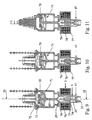
- the dosing device may be controlled by means of a data processing unit indicated schematically in Fig. 1 by the reference numeral 75.
- the data processing unit 75 may, for instance, comprise a personal computer and appropriate hardware for the interface between the computer and the bottle holder, which comprises the electromagnetic coil, the switch in the form of the lever arm 7, and possibly a not shown lamp for the indication of dispensing taken.
- the parts constituting the data processing unit 75 may be located at any place suitable in relation to the bottle holder.
- the first armature 28 is at its bottom side provided with a projection 45 having a T-shaped cross section, over which a valve body 51 of a liquid outlet valve 47 grips.
- the valve body 51 is made of elastic material and is in Fig. 3 shown in a position closing against a corresponding valve seat 46 of the liquid outlet valve 47.
- a mouth 48 of the outlet spout 5 has an internal tamper shield 49 mounted by means of ribs 50, so that the valve body 51 is inaccessible from the outside of the outlet spout 5.
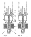
- Figs. 5 and 6 show another embodiment of the dosing device according to the invention, whereby the first armature 28 activates the liquid outlet valve 47 in the same way as in the embodiment shown in Figs. 3 and 4.
- the first armature 28 also activates a liquid inlet valve 57, but a valve body 67 of the liquid inlet valve 57 is in this embodiment arranged centrally in relation to an annular air intake valve 58 and is connected to the first armature 28 by means of a central rod 59.
- a valve body 68 of the annular air intake valve 58 is connected to and activated by the second armature 29 by means of three longitudinally extending rods 60 arranged around the central rod 59.
- the function of this embodiment is similar to the embodiment of Figs. 3 and 4.
Landscapes
- Engineering & Computer Science (AREA)
- Mechanical Engineering (AREA)
- Physics & Mathematics (AREA)
- Fluid Mechanics (AREA)
- General Physics & Mathematics (AREA)
- Devices For Dispensing Beverages (AREA)
- Nozzles (AREA)
- Feeding And Controlling Fuel (AREA)
- Loading And Unloading Of Fuel Tanks Or Ships (AREA)
- Supplying Of Containers To The Packaging Station (AREA)
- Infusion, Injection, And Reservoir Apparatuses (AREA)
- Auxiliary Devices For And Details Of Packaging Control (AREA)
- Filling Of Jars Or Cans And Processes For Cleaning And Sealing Jars (AREA)
Claims (17)
- Dosiervorrichtung (6) zur Befestigung an einem Behälter, wobei die Dosiervorrichtung eine Dosierkammer (14) aufweist, die einem Flüssigkeitseinlassventil (23, 57, 70) zur Verbindung mit dem Behälter und einem Flüssigkeitsauslassventil (47) zur Verbindung mit einer Öffnung (48) eines Auslassstutzens (5) zugeordnet ist, wobei der Auslassstutzen benachbart zu der Dosierkammer angeordnet ist und einen wesentlich kleineren Außendurchmesser als diese hat, wobei jedes von dieses Ventilen (23, 57, 70, 47) einen Ventilkörper (22, 67, 72, 51) hat, der durch Verlagerung eines in dem Auslassstutzen angeordneten Ankers (28) zwischen einer geschlossenen Position und einer offenen Position verlagerbar ist, wobei der Anker mit Hilfe eines magnetischen Feldes verlagerbar ist, das durch eine elektromagnetische Spule (3) erzeugt wird, in die der Stutzen eingeführt werden kann, wobei die Dosiervorrichtung zwischen einem Beladungszustand, in dem das Flüssigkeitseinlassventil geöffnet ist und das Flüssigkeitsauslassventil geschlossen ist, und einem Abgabezustand betrieben werden kann, in dem das Flüssigkeitseinlassventil geschlossen ist und das Flüssigkeitsauslassventil geöffnet ist, und wobei die Dosierkammer mit einem Lufteinlass (40, 42) zur Verbindung mit der Umgebung während des Abgabezustands der Dosiervorrichtung ausgestattet ist, dadurch gekennzeichnet, dass der Stutzen zwei Anker (28, 29) aufweist, die angepasst sind, um einander mit Hilfe einer magnetischen Kraft zu beeinflussen, und dadurch, dass der Lufteinlass der Dosierkammer mit einem Lufteinlassventil (37) ausgestattet ist, das einen Ventilkörper (36) aufweist, der zwischen einer geschlossenen Position in dem Beladungszustand der Dosiervorrichtung und einer geöffneten Position in dem Abgabezustand der Dosiervorrichtung betrieben werden kann.
- Dosiervorrichtung nach Anspruch 1, dadurch gekennzeichnet, dass der Durchmesser des Ventilkörpers (51) des Flüssigkeitsauslassventils (47) kleiner als der Außendurchmesser des Auslassstutzens (5) ist.
- Dosiervorrichtung nach Anspruch 1, dadurch gekennzeichnet, dass zwischen der Dosierkammer (14) und dem Auslassstutzen (5) in dem Beladungszustand der Dosiervorrichtung ein freier Durchgang vorgesehen ist.
- Dosiervorrichtung nach Anspruch 1, dadurch gekennzeichnet, dass der Ventilkörper (51) des Flüssigkeitsauslassventils (47) an der Öffnung (48) des Auslassstutzens (5) angeordnet ist.
- Dosiervorrichtung nach einem der vorhergehenden Ansprüche, dadurch gekennzeichnet, dass der Ventilkörper (22, 67, 72) des Flüssigkeitseinlassventils (23, 57, 70) und der Ventilkörper (36, 68, 62) des Lufteinlassventils (37, 58, 61, 71) konzentrisch angeordnet sind.
- Dosiervorrichtung nach einem der vorhergehenden Ansprüche, dadurch gekennzeichnet, dass der Ventilkörper (22) des Flüssigkeitseinlassventils (23) die Form eines Rings hat, und dadurch, dass der Ventilkörper (36, 62) des Lufteinlassventils (37, 61) an dem Zentrum des Ventilkörpers (22) des Flüssigkeitseinlassventils (23) angeordnet ist.
- Dosiervorrichtung nach Anspruch 6, dadurch gekennzeichnet, dass in einer oberen Wand (16) der Dosierkammer (14) ein Ventilsitz für den Ventilkörper (22) des Flüssigkeitseinlassventils (23) in der Form eines äußeren Ringsitzes (18) und eines inneren Ringsitzes (19) vorgesehen ist, die dazwischen eine Flüssigkeitseinlassöffnung (17) bilden, wobei die Flüssigkeitseinlassöffnung mit einem in einen Hals des Behälters einzuführenden Befestigungsabschnitt (9) der Dosierkammer in Verbindung steht, und dadurch, dass ein Ventilsitz (38) für den Ventilkörper (36) des Lufteinlassventils (37) um eine Lufteinlassöffnung (39) herum angeordnet ist, die mittig in dem inneren Ringsitz (19) des Flüssigkeitseinlassventils (23) angeordnet ist, wobei die Lufteinlassöffnung (39) durch einen Luftkanal (40) mit der Umgebung in Verbindung steht, der in einem Querelement angeordnet ist, das radial an der oberen Wand (16) der Dosierkammer (14) verläuft.
- Dosiervorrichtung nach Anspruch 7, dadurch gekennzeichnet, dass sich der Luftkanal (40), der in dem Querelement angeordnet ist, in einen Umfangskanal (42) öffnet, der in der Außenseite der oberen Wand (16) der Dosierkammer (14) angeordnet ist, wobei der Umfangskanal (42) durch eine Öffnung (43), die in der Richtung des Umfangskanals in einer Entfernung von der Öffnung des radialen Luftkanals (40) angeordnet ist, mit der Umgebung in Verbindung steht.
- Dosiervorrichtung nach einem der vorhergehenden Ansprüche, dadurch gekennzeichnet, dass die Anker (28, 29) mit Hilfe einer Druckfeder (30) voneinander weg vorgespannt sind.
- Dosiervorrichtung nach einem der vorhergehenden Ansprüche, dadurch gekennzeichnet, dass die Anker (28, 29) zwischen Längsrippen (52) in dem Auslassstutzen (5) geführt sind.
- Dosiervorrichtung nach einem der vorhergehenden Ansprüche, dadurch gekennzeichnet, dass der Ventilkörper (22, 67) des Flüssigkeitseinlassventils (23, 57) und der Ventilkörper (51) des Flüssigkeitsauslassventils (47) an mindestens einer gemeinsamen Stange (25, 59) befestigt sind, die mit Hilfe eines ersten (28) der zwei Anker verlagerbar ist.
- Dosiervorrichtung nach Anspruch 11, dadurch gekennzeichnet, dass der Ventilkörper (36) des Lufteinlassventils (37) an einer Stange (35) befestigt ist, die mit Hilfe eines zweiten (29) der zwei Anker verlagerbar ist.
- Dosiervorrichtung nach Anspruch 12, dadurch gekennzeichnet, dass der erste Anker (28) mit dem Ventilkörper (22) des Flüssigkeitseinlassventils (23) mit Hilfe von mindestens zwei Stangen (25) verbunden ist, die um die zentrale Stange (35) herum angeordnet und in Vertiefungen (54) in dem zweiten Anker (29) aufgenommen sind.
- Dosiervorrichtung nach einem der Ansprüche 12 bis 13, dadurch gekennzeichnet, dass der zweite Anker (29) eine Schulter (55) aufweist, die angepasst ist, um in dem Abgabezustand der Dosiervorrichtung an einem Vorsprung (56) an dem Auslassstutzen (5) anzuliegen und dadurch die Verlagerung des zweiten Ankers zu begrenzen.
- Dosiervorrichtung nach einem der Ansprüche 1 bis 10, dadurch gekennzeichnet, dass der Ventilkörper (72) des Flüssigkeitseinlassventils (70) mit Hilfe des zweiten Ankers (29) verlagerbar ist, und dadurch, dass der Ventilkörper (51) des Flüssigkeitsauslassventils (47) mit Hilfe des ersten Ankers (28) verlagerbar ist.
- Dosiervorrichtung nach einem der vorhergehenden Ansprüche, dadurch gekennzeichnet, dass zwischen dem ersten Anker (28) und dem zweiten Anker (29) ein magnetisierbarer dritter Anker (74) stationär in dem Auslassstutzen (5) befestigt ist.
- System zur Abgabe von Flüssigkeit oder dergleichen, das einen Flaschenhalter (2) mit einer elektromagnetischen Spule (3) und eine Dosiervorrichtung (6) gemäß einem der vorhergehenden Ansprüche zur Einführung in die Spule sowie eine Datenverarbeitungseinheit (75) zur Steuerung des magnetischen Feldes der Spule zur Abgabe vordefinierter Mengen von Flüssigkeit und zur Erfassung der Anzahl abgegebener Getränke aufweist.
Priority Applications (4)
| Application Number | Priority Date | Filing Date | Title |
|---|---|---|---|
| EP04388034A EP1598311B1 (de) | 2004-05-18 | 2004-05-18 | Dosiervorrichtung zur Behältermontage |
| DE602004007493T DE602004007493D1 (de) | 2004-05-18 | 2004-05-18 | Dosiervorrichtung zur Behältermontage |
| AT04388034T ATE366709T1 (de) | 2004-05-18 | 2004-05-18 | Dosiervorrichtung zur behältermontage |
| US11/129,500 US20050263547A1 (en) | 2004-05-18 | 2005-05-16 | Dosing device for mounting on a container |
Applications Claiming Priority (1)
| Application Number | Priority Date | Filing Date | Title |
|---|---|---|---|
| EP04388034A EP1598311B1 (de) | 2004-05-18 | 2004-05-18 | Dosiervorrichtung zur Behältermontage |
Publications (3)
| Publication Number | Publication Date |
|---|---|
| EP1598311A1 EP1598311A1 (de) | 2005-11-23 |
| EP1598311A8 EP1598311A8 (de) | 2006-05-17 |
| EP1598311B1 true EP1598311B1 (de) | 2007-07-11 |
Family
ID=34931938
Family Applications (1)
| Application Number | Title | Priority Date | Filing Date |
|---|---|---|---|
| EP04388034A Expired - Lifetime EP1598311B1 (de) | 2004-05-18 | 2004-05-18 | Dosiervorrichtung zur Behältermontage |
Country Status (4)
| Country | Link |
|---|---|
| US (1) | US20050263547A1 (de) |
| EP (1) | EP1598311B1 (de) |
| AT (1) | ATE366709T1 (de) |
| DE (1) | DE602004007493D1 (de) |
Families Citing this family (14)
| Publication number | Priority date | Publication date | Assignee | Title |
|---|---|---|---|---|
| CA2620921A1 (en) * | 2005-08-29 | 2007-03-08 | Digitot International (Pty) Limited | Apparatus for dispensing a metered quantity of liquor |
| WO2007144002A1 (en) * | 2006-06-16 | 2007-12-21 | Wircon A/S | A pouring stopper |
| US7832599B2 (en) * | 2007-07-16 | 2010-11-16 | Rodney Laible | Dispensing and/or dosing system |
| US7841492B2 (en) * | 2007-07-16 | 2010-11-30 | Rodney Laible | Anti-drip valve for a dispensing and/or dosing system |
| US8066157B2 (en) * | 2007-07-16 | 2011-11-29 | Rodney Laible | Dispensing and/or dosing system including an improved throat plug assembly |
| GB2451635B (en) | 2007-08-06 | 2012-03-28 | Diageo Great Britain Ltd | Apparatus for dispensing a carbonated beverage |
| US8925769B2 (en) | 2008-05-08 | 2015-01-06 | Automatic Bar Controls, Inc. | Wireless spout and system for dispensing |
| US20090277931A1 (en) | 2008-05-08 | 2009-11-12 | Achim Philipp Zapp | Wireless spout and system for free-and pre-measured dispensing |
| CA2832292C (en) * | 2011-04-21 | 2019-08-06 | Controles Bvl Ltee | Liquid dispensing system having a portable handheld activator |
| US8695858B2 (en) | 2011-09-07 | 2014-04-15 | Achim Philipp Zapp | Air valves for a wireless spout and system for dispensing |
| ITPD20130041A1 (it) * | 2013-02-25 | 2014-08-26 | T T S S R L Tecno Trolley System | Corpo valvola di un dispositivo dosatore |
| US9624085B1 (en) * | 2015-12-30 | 2017-04-18 | Arganius E Peckels | Unimpeded measured pourer device |
| US10723610B2 (en) * | 2016-09-26 | 2020-07-28 | Gate Cfv Solutions, Inc. | Magnetically controlled valve using a blocking device and a movement device |
| CN111632181B (zh) * | 2020-04-28 | 2024-10-29 | 广东科高电器有限公司 | 一种香薰机加液装置及香薰机 |
Family Cites Families (15)
| Publication number | Priority date | Publication date | Assignee | Title |
|---|---|---|---|---|
| US3258166A (en) * | 1963-11-19 | 1966-06-28 | Dagma G M B H & Co | Dispenser for liquids |
| US3802606A (en) * | 1972-05-05 | 1974-04-09 | Courtsey Prod Corp | Stopper type liquid dispensing apparatus |
| US3920149A (en) * | 1973-11-23 | 1975-11-18 | Frank J Fortino | Beverage dispensing apparatus and method |
| DE2932558C2 (de) * | 1979-08-10 | 1983-03-24 | DAGMA Deutsche Automaten- und Getränkemaschinen GmbH & Co KG, 2067 Reinfeld | Vorrichtung zum genauen Dosieren von Fluids schwankender Viskosität, insb. stark viskosen Flüssigkeiten |
| US4288009A (en) * | 1980-03-18 | 1981-09-08 | Simmons Graham M A | Liquid measuring device |
| DK155586B (da) * | 1982-11-11 | 1989-04-24 | Hartwall Ltd | Doseringsapparat til udskaenkning af forudbestemte maengder af fortrinsvis en drikkevare fra en flaske |
| DE3409142A1 (de) * | 1984-03-13 | 1985-09-26 | Bosch-Siemens Hausgeräte GmbH, 7000 Stuttgart | Anordnung zur dosierten abgabe von fluessigkeiten |
| DE3509189C1 (de) * | 1985-03-14 | 1986-05-15 | Peter 3300 Braunschweig Albrecht | Vorrichtung zum dosierten Ausschenken und Registrieren von Fluessigkeiten |
| DE3622745A1 (de) * | 1986-07-07 | 1988-02-04 | Bosch Siemens Hausgeraete | Getraenkekonzentrats-vorratsbehaelter zum einsatz in getraenkeautomaten |
| AU630377B2 (en) * | 1988-12-16 | 1992-10-29 | Itw New Zealand Limited | Dispenser |
| US5132482A (en) * | 1990-06-14 | 1992-07-21 | Alberta Research Council | Process for the oxidative coupling of methane to higher hydrocarbons |
| JP3696668B2 (ja) * | 1995-09-27 | 2005-09-21 | ソニー株式会社 | 非水電解液二次電池 |
| US5702032A (en) * | 1995-11-27 | 1997-12-30 | Dec International, Inc. | Beverage dispensing system with bottle identification rings |
| US6036055A (en) * | 1996-11-12 | 2000-03-14 | Barmate Corporation | Wireless liquid portion and inventory control system |
| DE60201094T2 (de) * | 2001-01-24 | 2005-10-13 | Lindberg & Jensen Aps | Dosiervorrichtung für einen Behälter |
-
2004
- 2004-05-18 EP EP04388034A patent/EP1598311B1/de not_active Expired - Lifetime
- 2004-05-18 DE DE602004007493T patent/DE602004007493D1/de not_active Expired - Lifetime
- 2004-05-18 AT AT04388034T patent/ATE366709T1/de not_active IP Right Cessation
-
2005
- 2005-05-16 US US11/129,500 patent/US20050263547A1/en not_active Abandoned
Non-Patent Citations (1)
| Title |
|---|
| None * |
Also Published As
| Publication number | Publication date |
|---|---|
| DE602004007493D1 (de) | 2007-08-23 |
| ATE366709T1 (de) | 2007-08-15 |
| EP1598311A1 (de) | 2005-11-23 |
| EP1598311A8 (de) | 2006-05-17 |
| US20050263547A1 (en) | 2005-12-01 |
Similar Documents
| Publication | Publication Date | Title |
|---|---|---|
| EP1227058B1 (de) | Dosiervorrichtung für einen Behälter | |
| US20050263547A1 (en) | Dosing device for mounting on a container | |
| JP3510243B2 (ja) | シロップディスペンサー用弁組立体 | |
| EP0254138B1 (de) | Behälterverschluss mit Dosiereinrichtung | |
| US5497917A (en) | Cap for a beverage server | |
| US8783512B2 (en) | Dosing spout and system | |
| KR100235817B1 (ko) | 분배 밸브 조립체 | |
| JP2003530279A (ja) | 液体用分配バルブ | |
| EP1324943A1 (de) | Flüssigkeitsabgabeverschlusselement | |
| AU2001296840A1 (en) | Fluid dispensing closure | |
| CA2022786C (en) | Metering dispenser for liquids | |
| CA1164419A (en) | Dispensing and metering devices for liquids | |
| JPH0833317B2 (ja) | 用量投与システム及び方法 | |
| DK155586B (da) | Doseringsapparat til udskaenkning af forudbestemte maengder af fortrinsvis en drikkevare fra en flaske | |
| CN109279170B (zh) | 用于分配多种流体产品的装置 | |
| US6641006B2 (en) | Container stopper | |
| US10591337B1 (en) | Dispensing cup for aerosol device | |
| US20030150886A1 (en) | Cap for a beverage server | |
| AU698520B2 (en) | A measure | |
| EP2727878A1 (de) | Portable Vorrichtung zum Konservieren und Ausschenken von Wein | |
| KR910008178B1 (ko) | 점도보상수단을 구비한 액체분배용의 일회용 팩케이지 및 펙케이지용 장치 | |
| US689468A (en) | Measuring-faucet. | |
| GB2586031A (en) | Beverage dispensing system | |
| KR20130079416A (ko) | 액체 용기 및 충전 장치를 포함하는 키트 | |
| EP1809549B1 (de) | Ventile für trinkbecher |
Legal Events
| Date | Code | Title | Description |
|---|---|---|---|
| PUAI | Public reference made under article 153(3) epc to a published international application that has entered the european phase |
Free format text: ORIGINAL CODE: 0009012 |
|
| AK | Designated contracting states |
Kind code of ref document: A1 Designated state(s): AT BE BG CH CY CZ DE DK EE ES FI FR GB GR HU IE IT LI LU MC NL PL PT RO SE SI SK TR |
|
| AX | Request for extension of the european patent |
Extension state: AL HR LT LV MK |
|
| RIN1 | Information on inventor provided before grant (corrected) |
Inventor name: LINDBERG, FRANK Inventor name: JENSEN, BJOERN SLOT Inventor name: LINDBERG, PETER |
|
| 17P | Request for examination filed |
Effective date: 20060519 |
|
| AKX | Designation fees paid |
Designated state(s): AT BE BG CH CY CZ DE DK EE ES FI FR GB GR HU IE IT LI LU MC NL PL PT RO SE SI SK TR |
|
| GRAP | Despatch of communication of intention to grant a patent |
Free format text: ORIGINAL CODE: EPIDOSNIGR1 |
|
| GRAS | Grant fee paid |
Free format text: ORIGINAL CODE: EPIDOSNIGR3 |
|
| GRAA | (expected) grant |
Free format text: ORIGINAL CODE: 0009210 |
|
| AK | Designated contracting states |
Kind code of ref document: B1 Designated state(s): AT BE BG CH CY CZ DE DK EE ES FI FR GB GR HU IE IT LI LU MC NL PL PT RO SE SI SK TR |
|
| REG | Reference to a national code |
Ref country code: GB Ref legal event code: FG4D |
|
| REG | Reference to a national code |
Ref country code: CH Ref legal event code: EP |
|
| REF | Corresponds to: |
Ref document number: 602004007493 Country of ref document: DE Date of ref document: 20070823 Kind code of ref document: P |
|
| REG | Reference to a national code |
Ref country code: IE Ref legal event code: FG4D |
|
| PG25 | Lapsed in a contracting state [announced via postgrant information from national office to epo] |
Ref country code: NL Free format text: LAPSE BECAUSE OF FAILURE TO SUBMIT A TRANSLATION OF THE DESCRIPTION OR TO PAY THE FEE WITHIN THE PRESCRIBED TIME-LIMIT Effective date: 20070711 Ref country code: FI Free format text: LAPSE BECAUSE OF FAILURE TO SUBMIT A TRANSLATION OF THE DESCRIPTION OR TO PAY THE FEE WITHIN THE PRESCRIBED TIME-LIMIT Effective date: 20070711 Ref country code: PT Free format text: LAPSE BECAUSE OF FAILURE TO SUBMIT A TRANSLATION OF THE DESCRIPTION OR TO PAY THE FEE WITHIN THE PRESCRIBED TIME-LIMIT Effective date: 20071211 Ref country code: BG Free format text: LAPSE BECAUSE OF FAILURE TO SUBMIT A TRANSLATION OF THE DESCRIPTION OR TO PAY THE FEE WITHIN THE PRESCRIBED TIME-LIMIT Effective date: 20071011 Ref country code: ES Free format text: LAPSE BECAUSE OF FAILURE TO SUBMIT A TRANSLATION OF THE DESCRIPTION OR TO PAY THE FEE WITHIN THE PRESCRIBED TIME-LIMIT Effective date: 20071022 |
|
| REG | Reference to a national code |
Ref country code: CH Ref legal event code: PL |
|
| NLV1 | Nl: lapsed or annulled due to failure to fulfill the requirements of art. 29p and 29m of the patents act | ||
| PG25 | Lapsed in a contracting state [announced via postgrant information from national office to epo] |
Ref country code: CH Free format text: LAPSE BECAUSE OF FAILURE TO SUBMIT A TRANSLATION OF THE DESCRIPTION OR TO PAY THE FEE WITHIN THE PRESCRIBED TIME-LIMIT Effective date: 20070711 Ref country code: AT Free format text: LAPSE BECAUSE OF FAILURE TO SUBMIT A TRANSLATION OF THE DESCRIPTION OR TO PAY THE FEE WITHIN THE PRESCRIBED TIME-LIMIT Effective date: 20070711 Ref country code: LI Free format text: LAPSE BECAUSE OF FAILURE TO SUBMIT A TRANSLATION OF THE DESCRIPTION OR TO PAY THE FEE WITHIN THE PRESCRIBED TIME-LIMIT Effective date: 20070711 Ref country code: PL Free format text: LAPSE BECAUSE OF FAILURE TO SUBMIT A TRANSLATION OF THE DESCRIPTION OR TO PAY THE FEE WITHIN THE PRESCRIBED TIME-LIMIT Effective date: 20070711 |
|
| EN | Fr: translation not filed | ||
| PG25 | Lapsed in a contracting state [announced via postgrant information from national office to epo] |
Ref country code: BE Free format text: LAPSE BECAUSE OF FAILURE TO SUBMIT A TRANSLATION OF THE DESCRIPTION OR TO PAY THE FEE WITHIN THE PRESCRIBED TIME-LIMIT Effective date: 20070711 |
|
| PG25 | Lapsed in a contracting state [announced via postgrant information from national office to epo] |
Ref country code: GR Free format text: LAPSE BECAUSE OF FAILURE TO SUBMIT A TRANSLATION OF THE DESCRIPTION OR TO PAY THE FEE WITHIN THE PRESCRIBED TIME-LIMIT Effective date: 20071012 Ref country code: DK Free format text: LAPSE BECAUSE OF FAILURE TO SUBMIT A TRANSLATION OF THE DESCRIPTION OR TO PAY THE FEE WITHIN THE PRESCRIBED TIME-LIMIT Effective date: 20070711 |
|
| PLBE | No opposition filed within time limit |
Free format text: ORIGINAL CODE: 0009261 |
|
| STAA | Information on the status of an ep patent application or granted ep patent |
Free format text: STATUS: NO OPPOSITION FILED WITHIN TIME LIMIT |
|
| PG25 | Lapsed in a contracting state [announced via postgrant information from national office to epo] |
Ref country code: CZ Free format text: LAPSE BECAUSE OF FAILURE TO SUBMIT A TRANSLATION OF THE DESCRIPTION OR TO PAY THE FEE WITHIN THE PRESCRIBED TIME-LIMIT Effective date: 20070711 Ref country code: SK Free format text: LAPSE BECAUSE OF FAILURE TO SUBMIT A TRANSLATION OF THE DESCRIPTION OR TO PAY THE FEE WITHIN THE PRESCRIBED TIME-LIMIT Effective date: 20070711 |
|
| 26N | No opposition filed |
Effective date: 20080414 |
|
| PG25 | Lapsed in a contracting state [announced via postgrant information from national office to epo] |
Ref country code: RO Free format text: LAPSE BECAUSE OF FAILURE TO SUBMIT A TRANSLATION OF THE DESCRIPTION OR TO PAY THE FEE WITHIN THE PRESCRIBED TIME-LIMIT Effective date: 20070711 Ref country code: SE Free format text: LAPSE BECAUSE OF FAILURE TO SUBMIT A TRANSLATION OF THE DESCRIPTION OR TO PAY THE FEE WITHIN THE PRESCRIBED TIME-LIMIT Effective date: 20071011 |
|
| PG25 | Lapsed in a contracting state [announced via postgrant information from national office to epo] |
Ref country code: DE Free format text: LAPSE BECAUSE OF FAILURE TO SUBMIT A TRANSLATION OF THE DESCRIPTION OR TO PAY THE FEE WITHIN THE PRESCRIBED TIME-LIMIT Effective date: 20071012 Ref country code: FR Free format text: LAPSE BECAUSE OF FAILURE TO SUBMIT A TRANSLATION OF THE DESCRIPTION OR TO PAY THE FEE WITHIN THE PRESCRIBED TIME-LIMIT Effective date: 20080307 |
|
| PG25 | Lapsed in a contracting state [announced via postgrant information from national office to epo] |
Ref country code: MC Free format text: LAPSE BECAUSE OF NON-PAYMENT OF DUE FEES Effective date: 20080531 |
|
| PG25 | Lapsed in a contracting state [announced via postgrant information from national office to epo] |
Ref country code: EE Free format text: LAPSE BECAUSE OF FAILURE TO SUBMIT A TRANSLATION OF THE DESCRIPTION OR TO PAY THE FEE WITHIN THE PRESCRIBED TIME-LIMIT Effective date: 20070711 |
|
| PG25 | Lapsed in a contracting state [announced via postgrant information from national office to epo] |
Ref country code: SI Free format text: LAPSE BECAUSE OF FAILURE TO SUBMIT A TRANSLATION OF THE DESCRIPTION OR TO PAY THE FEE WITHIN THE PRESCRIBED TIME-LIMIT Effective date: 20070711 |
|
| PG25 | Lapsed in a contracting state [announced via postgrant information from national office to epo] |
Ref country code: CY Free format text: LAPSE BECAUSE OF FAILURE TO SUBMIT A TRANSLATION OF THE DESCRIPTION OR TO PAY THE FEE WITHIN THE PRESCRIBED TIME-LIMIT Effective date: 20070711 |
|
| PG25 | Lapsed in a contracting state [announced via postgrant information from national office to epo] |
Ref country code: HU Free format text: LAPSE BECAUSE OF FAILURE TO SUBMIT A TRANSLATION OF THE DESCRIPTION OR TO PAY THE FEE WITHIN THE PRESCRIBED TIME-LIMIT Effective date: 20080112 Ref country code: LU Free format text: LAPSE BECAUSE OF NON-PAYMENT OF DUE FEES Effective date: 20080518 |
|
| PG25 | Lapsed in a contracting state [announced via postgrant information from national office to epo] |
Ref country code: TR Free format text: LAPSE BECAUSE OF FAILURE TO SUBMIT A TRANSLATION OF THE DESCRIPTION OR TO PAY THE FEE WITHIN THE PRESCRIBED TIME-LIMIT Effective date: 20070711 |
|
| PG25 | Lapsed in a contracting state [announced via postgrant information from national office to epo] |
Ref country code: IT Free format text: LAPSE BECAUSE OF NON-PAYMENT OF DUE FEES Effective date: 20080531 |
|
| PGFP | Annual fee paid to national office [announced via postgrant information from national office to epo] |
Ref country code: IE Payment date: 20121130 Year of fee payment: 9 |
|
| REG | Reference to a national code |
Ref country code: IE Ref legal event code: MM4A |
|
| PG25 | Lapsed in a contracting state [announced via postgrant information from national office to epo] |
Ref country code: IE Free format text: LAPSE BECAUSE OF NON-PAYMENT OF DUE FEES Effective date: 20130518 |
|
| PGFP | Annual fee paid to national office [announced via postgrant information from national office to epo] |
Ref country code: GB Payment date: 20170531 Year of fee payment: 14 |
|
| GBPC | Gb: european patent ceased through non-payment of renewal fee |
Effective date: 20180518 |
|
| PG25 | Lapsed in a contracting state [announced via postgrant information from national office to epo] |
Ref country code: GB Free format text: LAPSE BECAUSE OF NON-PAYMENT OF DUE FEES Effective date: 20180518 |