EP1598309B1 - Vorrichtung zum Füllen von Behältern mit einem Füllventil - Google Patents
Vorrichtung zum Füllen von Behältern mit einem Füllventil Download PDFInfo
- Publication number
- EP1598309B1 EP1598309B1 EP20050103844 EP05103844A EP1598309B1 EP 1598309 B1 EP1598309 B1 EP 1598309B1 EP 20050103844 EP20050103844 EP 20050103844 EP 05103844 A EP05103844 A EP 05103844A EP 1598309 B1 EP1598309 B1 EP 1598309B1
- Authority
- EP
- European Patent Office
- Prior art keywords
- central body
- conduit
- delivery
- chambers
- chamber
- Prior art date
- Legal status (The legal status is an assumption and is not a legal conclusion. Google has not performed a legal analysis and makes no representation as to the accuracy of the status listed.)
- Expired - Lifetime
Links
- 235000013361 beverage Nutrition 0.000 claims description 33
- 238000005192 partition Methods 0.000 claims description 26
- 238000013022 venting Methods 0.000 claims description 16
- 238000011084 recovery Methods 0.000 claims description 10
- 239000007788 liquid Substances 0.000 description 17
- 238000000034 method Methods 0.000 description 7
- 230000000694 effects Effects 0.000 description 6
- 238000011012 sanitization Methods 0.000 description 6
- 238000010276 construction Methods 0.000 description 5
- 239000012530 fluid Substances 0.000 description 4
- 230000008569 process Effects 0.000 description 4
- 238000005452 bending Methods 0.000 description 3
- 230000006872 improvement Effects 0.000 description 3
- CURLTUGMZLYLDI-UHFFFAOYSA-N Carbon dioxide Chemical compound O=C=O CURLTUGMZLYLDI-UHFFFAOYSA-N 0.000 description 2
- 235000014171 carbonated beverage Nutrition 0.000 description 2
- 238000005187 foaming Methods 0.000 description 2
- 238000004519 manufacturing process Methods 0.000 description 2
- 230000005587 bubbling Effects 0.000 description 1
- 229910002092 carbon dioxide Inorganic materials 0.000 description 1
- 239000001569 carbon dioxide Substances 0.000 description 1
- 238000004140 cleaning Methods 0.000 description 1
- 238000004891 communication Methods 0.000 description 1
- 230000002860 competitive effect Effects 0.000 description 1
- 230000001351 cycling effect Effects 0.000 description 1
- 230000001627 detrimental effect Effects 0.000 description 1
- 238000005429 filling process Methods 0.000 description 1
- 230000006870 function Effects 0.000 description 1
- 238000012423 maintenance Methods 0.000 description 1
- 230000004048 modification Effects 0.000 description 1
- 238000012986 modification Methods 0.000 description 1
- 230000001737 promoting effect Effects 0.000 description 1
- 230000000284 resting effect Effects 0.000 description 1
- 238000004904 shortening Methods 0.000 description 1
- 230000001360 synchronised effect Effects 0.000 description 1
Images

Classifications
-
- B—PERFORMING OPERATIONS; TRANSPORTING
- B67—OPENING, CLOSING OR CLEANING BOTTLES, JARS OR SIMILAR CONTAINERS; LIQUID HANDLING
- B67C—CLEANING, FILLING WITH LIQUIDS OR SEMILIQUIDS, OR EMPTYING, OF BOTTLES, JARS, CANS, CASKS, BARRELS, OR SIMILAR CONTAINERS, NOT OTHERWISE PROVIDED FOR; FUNNELS
- B67C3/00—Bottling liquids or semiliquids; Filling jars or cans with liquids or semiliquids using bottling or like apparatus; Filling casks or barrels with liquids or semiliquids
- B67C3/02—Bottling liquids or semiliquids; Filling jars or cans with liquids or semiliquids using bottling or like apparatus
- B67C3/22—Details
- B67C3/26—Filling-heads; Means for engaging filling-heads with bottle necks
- B67C3/2614—Filling-heads; Means for engaging filling-heads with bottle necks specially adapted for counter-pressure filling
- B67C3/2617—Filling-heads; Means for engaging filling-heads with bottle necks specially adapted for counter-pressure filling the liquid valve being opened by mechanical or electrical actuation
-
- B—PERFORMING OPERATIONS; TRANSPORTING
- B67—OPENING, CLOSING OR CLEANING BOTTLES, JARS OR SIMILAR CONTAINERS; LIQUID HANDLING
- B67C—CLEANING, FILLING WITH LIQUIDS OR SEMILIQUIDS, OR EMPTYING, OF BOTTLES, JARS, CANS, CASKS, BARRELS, OR SIMILAR CONTAINERS, NOT OTHERWISE PROVIDED FOR; FUNNELS
- B67C3/00—Bottling liquids or semiliquids; Filling jars or cans with liquids or semiliquids using bottling or like apparatus; Filling casks or barrels with liquids or semiliquids
- B67C3/02—Bottling liquids or semiliquids; Filling jars or cans with liquids or semiliquids using bottling or like apparatus
- B67C3/22—Details
- B67C3/28—Flow-control devices, e.g. using valves
-
- B—PERFORMING OPERATIONS; TRANSPORTING
- B67—OPENING, CLOSING OR CLEANING BOTTLES, JARS OR SIMILAR CONTAINERS; LIQUID HANDLING
- B67C—CLEANING, FILLING WITH LIQUIDS OR SEMILIQUIDS, OR EMPTYING, OF BOTTLES, JARS, CANS, CASKS, BARRELS, OR SIMILAR CONTAINERS, NOT OTHERWISE PROVIDED FOR; FUNNELS
- B67C3/00—Bottling liquids or semiliquids; Filling jars or cans with liquids or semiliquids using bottling or like apparatus; Filling casks or barrels with liquids or semiliquids
- B67C3/02—Bottling liquids or semiliquids; Filling jars or cans with liquids or semiliquids using bottling or like apparatus
- B67C3/22—Details
- B67C3/26—Filling-heads; Means for engaging filling-heads with bottle necks
- B67C2003/2671—Means for preventing foaming of the liquid
Definitions
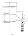
- the present invention refers to a filling valve of a particularly advanced type, which is adapted to be used in conjunction with industrial bottle filling equipment for bottling various kinds of beverages, including both carbonated beverages, i.e. beverages charged with carbon dioxide, and so-called "flat", i.e. non-carbonated ones.
- This kind of bottling equipment shall therefore be able to operate through almost continuous working cycles, i.e. under almost continuous-duty conditions, at very high filling rates and a minimum extent of interruptions in the working cycle thereof.
- EP 1 293 475 A2 Disclosed in EP 1 293 475 A2 is a kind of valve that is also provided with a pneumatic control of the liquid flowing into the bottle, said pneumatic control comprising an elastic diaphragm-like member 9; this kind of valve does not, however, solve any of the afore-mentioned problems, while further adding a considerable complication owing to the presence of a large number of parts and devices that add to the difficulty and the degree of criticalness in carrying out any sanitization process.
- the solution disclosed in the above-cited patent implies using an arrangement, in which the filling tube coming horizontally from the beverage tank or reservoir undergoes a first 90°-bending upwards in the direction of the valve, a second 90°-bending downstream of the valve, when it bends down from a vertical direction into a substantially horizontal one, and a third 90°-bending when it bends again into the vertical so as to fit and debouch into the bottle.
- AFILL From DE 19646595A1 (ALFILL) a filling valve for a bottling machine according to the preamble of claim 1 is divulged, which comprises a block houses funnels and several pipes interconnected via horizontal channels for supplying drinks; however the circumstance or having connecting pipes linked by channels which are horizontally oriented causes again the twin-face drawback of pressure loss and poor cleanability.
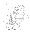
- an industrial beverage bottling apparatus comprises a plurality of bottle filling valves 1, which comprise:
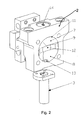
- Said central body is in the shape of a parallelepiped having vertical walls, and is provided internally with some recesses and some conduits, as indicated below.
- Said two chambers 7 and 8 are individually adjacent to and, therefore, open towards a common vertical side wall 10, while both the conformation and the arrangement thereof, along with the arrangement of said separating partition, are such that the overall line of intersection of said two chambers with said vertical wall 10 is a curved, preferably circular line that takes the form of a common closed edge 11, through which said two chambers and said separating partition are open towards the outside, i.e. are accessible from the outside from the side of said vertical wall 10.
- said vertical wall 10 is merely a geometrical surface, i.e. not a physical one.
- Said separating partition 9 is arranged between said two chambers in a manner as to enable the above-mentioned channel 9A connecting them with each other to extend along the same wall 10, as this readily appears in the illustrations in Figures 2 and 3.
- said wall 10 is viewed from the outside, there can be seen said two distinct chambers 7 and 8 as separated from each other by the edge 12 - oriented towards said wall 10 - of said separating partition 9.
- said separating partition delimits said buffer chamber 7 at the bottom and said delivery chamber 8 on top.
- a lower passage 13 connecting vertically, from the top downwards, said delivery chamber 8 with said filling conduit 3; similarly, there is arranged an upper passage 14 connecting vertically, from the bottom upwards, said buffer chamber 7 with said delivery conduit 5.
- said lower and upper passages, said two chambers 7 and 8 and said separating partition are positioned in a mutually aligned arrangement along a same vertical.
- the aperture that is so outwardly delimited by said closed edge 11, is however capable of being shut by a geometrically identical edge of an elastic diaphragm 16, which is arranged on a selectively actuatable pneumatic control member 15: according to the state of such pneumatic control member, said diaphragm can therefore be itself in a state in which it is either internally inflated, i.e. swollen up, or internally deflated, i.e. flattened out.
- the diaphragm retracts, thereby clearing said channel connecting the two chambers with each other.
- Said elastic diaphragm 16 and the related selectively actuatable pneumatic control member 15 are largely known as such in the art, so that they shall not be discussed or dealt with any further in this context.
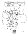
- said delivery chamber 8, or the related lower passage 13 is connected outwardly with a venting conduit 17, wherein said venting conduit performs as follows: upon completing a filling phase of a bottle with a carbonated-type beverage, and since the pressure in the bottle is at this point of approx. 3.5 bar (as a matter of fact, in view of preventing the beverage from bubbling over, the same beverage shall be kept at this pressure also during the bottling or filling phase and, therefore, even inside the bottle), the need arises - after the bottle has been so filled - for the pressure to be brought down again and, preferably, for the gas previously let into the bottle to be recovered.
- venting conduit 17 which is kept in a closed condition throughout the bottle filling phase and is only opened for a very short period of time just at the end of such bottle filling phase in view of recovering the gas and allowing the pressure inside the bottle to decrease.
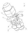
- said venting conduit 17 debouches into a side body 18, which is provided with a first valve member.
- This valve member is made with substantially the same construction, technical and working features of the afore-described valve; it therefore is provided with a respective buffer chamber 20, a respective delivery chamber 21, a respective separating partition 22 arranged therebetween, and a respective diaphragm 23, which, as duly provided with respective pneumatic control or actuation means 24, is adapted to selectively open/close the channel connecting said two chambers with each other; even in this case the two chambers and the related separating partition are aligned with each other vertically.
- Said two chambers 20 and 21 are connected to respective conduits. Specifically, the buffer chamber is connected to said venting conduit 17 via a vent 25, whereas the related delivery chamber is connected to a respective final conduit 26 debouching either outside, i.e. into the atmosphere, or into a gas recovery reservoir (not shown).
- These two chambers 20 and 21 may be arranged in any position relative to each other, but in a most advantageous manner - and for just the same reasons as already described and explained hereinbefore with reference to the buffer and delivery chambers 7 and 8 aligned along the same vertical - even these two chambers 20 and 21 are so positioned in a mutually aligned arrangement along the same vertical.
- a further improvement of the afore-described valve can be provided as follows: in correspondence to the lower wall 30 of said central body, there may in fact be provided a recovery channel 31, i.e. a through-passing channel debouching onto said lower wall 30 of said central body 2 with a port 32, as well as onto the wall of said central body 2 with a respective port 33.
- a recovery channel 31 i.e. a through-passing channel debouching onto said lower wall 30 of said central body 2 with a port 32, as well as onto the wall of said central body 2 with a respective port 33.
- Said port 32 is connected to a recovery tube (not shown), which is automatically inserted in the bottle when the latter is raised so as to be applied onto said filling conduit 3; on the other hand, the task performed by this recovery tube, which is used for bottling both carbonated and non-carbonated beverages, is largely known to all those skilled in the art, so that it shall not be discussed any further in this context.
- the outlet port 33 of said recovery channel 31 is in turn interconnected with a second conduit 34 of said side body 18, which is connected to the pressurizing and recovery means via a second respective, selectively actuatable valve means that is in turn incorporated in said side body 18.
- this valve member is made with substantially the same construction, technical and working features of the afore-described valve; it therefore is provided with a respective delivery chamber 40, a respective buffer chamber 41, a respective separating partition 42 arranged therebetween, and a respective diaphragm 43, which, as duly provided with respective pneumatic control or actuation means 44, is adapted to selectively open/close the channel connecting said two chambers with each other; advantageously, even in this case the two chambers and the related separating partition are aligned with each other vertically.
- Said two chambers 40 and 41 are connected to respective conduits. Specifically, the buffer chamber is connected to said second conduit 34, whereas the related delivery chamber is connected to a respective third conduit 46 debouching into the beverage recovery reservoir or pressurizing means (not shown).
- the related valve has its two chambers 40 and 41 and the related separating partition 42 situated therebetween mutually aligned along the same vertical, thereby attaining the same advantages in terms of cleanability and flow enhancement as already described with reference to the afore-discussed valves.
- said two valve members incorporated in the side body 18 are provided and arranged in such a manner as to enable both the respective buffer chambers 21 and 41 and delivery chambers 20 and 40, and the respective separating partitions 22 and 42 therebetween, to face and, hence, open towards a common vertical wall 45 of said side body 18.
- each one of said two valve means to be separated into respective devices which are in part incorporated in said side body 18, such as in the case of the buffer and delivery chambers and the related separating partition, and are accessible from the common outer wall 45, and are in part applied directly onto said same vertical wall 45 - on the outside thereof - as said two pneumatic actuating or control members 24 and 44 along with the respective diaphragms 23 and 43.
- said constructive configuration does not only significantly enhance accessibility for improved convenience in maintenance and servicing, but also improves production standardization to a remarkable extent.
Landscapes
- Filling Of Jars Or Cans And Processes For Cleaning And Sealing Jars (AREA)
Claims (10)
- Industrielle Flaschenbefüllungsvorrichtung, die mit einem Befüllungsventil (1) versehen ist, das aufweist:- einen zentralen Körper (2),- eine vertikale Befüllungsrohrleitung (3), die unterhalb des zentralen Körpers angeordnet ist,- einen Getränkevortatsbehälter (4), der das in Flaschen abzufüllende Getränk enthält,- eine Abgaberohrleitung (5), die den Getränkevorratsbehälter mit dem zentralen Körper verbindet,- eine elastische Membran (16), die in dem zentralen Körper (2) enthalten ist und als ein Ventilverschlusselement arbeitet, dadurch gekennzeichnet, dass, in dem zentralen Körper (2) vertikal fluchtend, von oben nach unten, eine Pufferkammer (7) und eine darunter befindliche Abgabekammer (8) angeordnet sind, und die Kammern lediglich teilweise durch eine gemeinsame Trennwand (9) voneinander getrennt sind, so dass diese zwei Kammern in Fluidverbindung miteinander stehen, und zwar durch einen Kanal (9A), der sich in dem Abschnitt des zentralen Körpers (2) erstreckt, der nicht durch die Trennwand (9) belegt ist, und dadurch, dass die Abgaberohrleitung (5), ein oberer Kanal (14), die Pufferkammer (7), die Abgabekammer (8), ein unterer Kanal (13) und die Befüllungsrohrleitung (3) sich in geradliniger, zueinander fluchtender Anordnung zueinander befinden, wodurch sie wie eine einzige geradlinige vertikale Rohrleitung aussehen und arbeiten.
- Industrielle Flaschenbefüllungsvorrichtung nach Anspruch 1, dadurch gekennzeichnet, dass:- die Pufferkammer (7) und die Abgabekammer (8) so angeordnet sind, dass sie zur selben vertikalen Wand (10) des zentralen Körpers hin offen sind, und der Kanal (9A) zwischen den zwei Kammern durch eine Außenkante (12) der Trennwand (9) sowie durch die vertikale Wand (10) begrenzt ist,- die Pufferkammer (7) mit der Abgaberohrleitung (5) mittels des oberen Kanals (14) verbunden ist, der sich innerhalb des zentralen Körpers erstreckt, und- die Abgabekammer (8) mit der Befüllungsrohrleitung (3) über den unteren Kanal (13) verbunden ist, der sich im zentralen Körper (2) erstreckt, wobei diese Kanäle zueinander vertikal fluchtend angeordnet sind.
- Industrielle Flaschenbefüllungsvorrichtung nach Anspruch 2, dadurch gekennzeichnet, dass der obere und untere Kanal (13, 14) im Wesentlichen zueinander vertikal fluchtend angeordnet sind.
- Industrielle Flaschenbefüllungsvortichtung nach Anspruch 2 oder 3, dadurch gekennzeichnet, dass an derselben vertikalen Wand (10), und in Übereinstimmung mit der Pufferkammer (7) und der Abgabekammer (8), die elastische Membran (16) angebracht ist, die ausgebildet ist, um durch eine pneumatische Betätigung oder eine Steuereinrichtung (15) betätigt zu werden, um den Kanal (9A) zwischen den zwei Kammern wahlweise zu schließen/zu öffnen.
- Industrielle Flaschenbefüllungsvorrichtung nach Anspruch 4, dadurch gekennzeichnet, dass die elastische Membran (16) so ausgebildet ist, dass ein Abschnitt von dieser auf die gesamte Außenkante (12) der Trennwand (9) aufgebracht ist.
- Industrielle Flaschenbefüllungsvorrichtung nach einem der vorhergehenden Ansprüche, dadurch gekennzeichnet, dass der zentrale Körper (2) mit einer Belüftungsrohrleitung (17) versehen ist, welche entweder die Abgabekammer (8) oder den unteren Kanal (13) mit dem Äußeren des zentralen Körpers (2) verbindet.
- Industrielle Flaschenbefüllungsvorrichtung nach Anspruch 6, dadurch gekennzeichnet, dass ein seitlicher Körper (18) in einer danebenliegenden Anordnung bezüglich des zentralen Körpers vorgesehen ist, und dass in dem seitlichen Körper eine erste Pufferkammer (20), eine jeweilige erste Abgabekammer (21) und eine jeweilige Trennwand (22) angeordnet sind, wobei die erste Pufferkammer (20) mit der Belüftungsrohrleitung über einen Luftkanal (25) verbunden ist, und die erste Abgabekammer (21) mit einer Endrohrleitung (26) verbunden ist, die zum Äußeren des seitlichen Körpers führt, und wobei die jeweiligen ersten Puffer- und Abgabekammern (20, 21) und eine Kante der Trennwand von einer Außenwand (45) des seitlichen Körpers (18) her zugänglich sind und zu dieser hin offen sind.
- Industrielle Flaschenbefüllungsvorrichtung nach Anspruch 7, dadurch gekennzeichnet, dass der zentrale Körper (2) mit einem Rückgewinnungs- oder Druckbeaufschlagungskanal (31) versehen ist, der die untere Wand (30) des zentralen Körpers mit einer Seitenwand von dieser verbindet; dass ein seitlicher Körper (18) auf einer Seite des zentralen Körpers angeordnet ist; dass in dem seitlichen Körper eine zweite Pufferkammer (41), eine jeweilige zweite Abgabekammer (40) und eine jeweilige zweite Trennwand (42) vorgesehen ist, wobei die zweite Pufferkammer (41) mit dem Rückgewinnungskanal (31) über eine zweite Rohrleitung (34) verbunden ist, und die zweite Abgabekammer (40) mit einer zum Äußeren des seitlichen Körpers führenden dritten Rohrleitung (46) verbunden ist.
- Industrielle Flaschenbefüllungsvorrichtung nach Anspruch 8, dadurch gekennzeichnet, dass mindestens eine der ersten oder zweiten Pufferkammern (20, 41) und der jeweiligen Abgabekammern (41, 40), sowie die jeweiligen Trennwände (22, 42) entlang derselben Vertikale fluchtend angeordnet sind.
- Industrielle Flaschenbefüllungsvorrichtung nach Anspruch 8 oder 9, dadurch gekennzeichnet, dass die Pufferkammern (20, 41) und die jeweiligen Abgabekammern (21, 40) sowie die jeweiligen Trennwände (22, 42) von einer Außenwand (45) des seitlichen Körpers (18) her zugänglich sind und zu dieser hin offen sind.
Applications Claiming Priority (2)
| Application Number | Priority Date | Filing Date | Title |
|---|---|---|---|
| ITPN20040035 ITPN20040035A1 (it) | 2004-05-20 | 2004-05-20 | Impianto di imbottigliamento industriale dotato di valvola di riempimento perfezionata |
| ITPN20040035 | 2004-05-20 |
Publications (2)
| Publication Number | Publication Date |
|---|---|
| EP1598309A1 EP1598309A1 (de) | 2005-11-23 |
| EP1598309B1 true EP1598309B1 (de) | 2007-01-10 |
Family
ID=34939749
Family Applications (1)
| Application Number | Title | Priority Date | Filing Date |
|---|---|---|---|
| EP20050103844 Expired - Lifetime EP1598309B1 (de) | 2004-05-20 | 2005-05-10 | Vorrichtung zum Füllen von Behältern mit einem Füllventil |
Country Status (3)
| Country | Link |
|---|---|
| EP (1) | EP1598309B1 (de) |
| DE (1) | DE602005000429D1 (de) |
| IT (1) | ITPN20040035A1 (de) |
Family Cites Families (2)
| Publication number | Priority date | Publication date | Assignee | Title |
|---|---|---|---|---|
| DE19646595C2 (de) * | 1996-11-12 | 1998-09-24 | Alfill Engineering Gmbh & Co K | Getränkefüllorgan mit ventilgesteuerten Leitungen |
| ITBO20000409A1 (it) * | 2000-07-07 | 2002-01-07 | Stk Stocchi Progetti S R L | Perfezionamenti ai rubinetti degli impianti di imbottigliamento . |
-
2004
- 2004-05-20 IT ITPN20040035 patent/ITPN20040035A1/it unknown
-
2005
- 2005-05-10 DE DE200560000429 patent/DE602005000429D1/de not_active Expired - Lifetime
- 2005-05-10 EP EP20050103844 patent/EP1598309B1/de not_active Expired - Lifetime
Also Published As
| Publication number | Publication date |
|---|---|
| DE602005000429D1 (de) | 2007-02-22 |
| ITPN20040035A1 (it) | 2004-08-20 |
| EP1598309A1 (de) | 2005-11-23 |
Similar Documents
| Publication | Publication Date | Title |
|---|---|---|
| US3443608A (en) | Apparatus for filling containers with beverages | |
| US8678048B2 (en) | Device for dispensing effervescent beverages and a three-way valve | |
| US7287562B2 (en) | Filling valve | |
| EP1908726B1 (de) | Isobare Rotationsfüllmaschine zur Füllung von Containern mit Flüssigkeiten | |
| JP4459766B2 (ja) | ボトル、カン等のような容器のための処理機械 | |
| EP1683755B1 (de) | Zapfeinheit und Behälter | |
| EP0641736B1 (de) | Reinigungsvorrichtung für ein abgabesystem von getränken | |
| JP2002520237A (ja) | 飲料容器のバルブ組立品、飲料容器並びに飲料容器を充填し又空にする方法 | |
| EP3176126A1 (de) | Füllvorrichtung für eine füllmaschine | |
| KR20170042637A (ko) | 다수의 용기를 위한 음료 분배 기기 | |
| JP7522598B2 (ja) | 多機能充填バルブ | |
| KR102783154B1 (ko) | 분배 시스템 및 사용 방법 | |
| CA2325270A1 (en) | High speed beverage dispensing method and apparatus | |
| EP1598309B1 (de) | Vorrichtung zum Füllen von Behältern mit einem Füllventil | |
| RU2693523C1 (ru) | Способ, обрабатывающая станция и обрабатывающая головка для обработки внутреннего пространства кегов, и уплотнение, используемое в такой обрабатывающей станции | |
| US4928855A (en) | Dispenser apparatus for beverage bottles | |
| US3032077A (en) | Back-pressure racking apparatus for racking especially carbon dioxide containing beverages | |
| KR20190003667A (ko) | 발포 탄산 음료들을 수동으로 따르는 장치를 위한 유량 스위치 | |
| CN103145081A (zh) | 用于制造pet桶状容器的设备和方法 | |
| CN102811940B (zh) | 用于分配加压液体的设备 | |
| AU4583193A (en) | A process for filling containers, in particular cans, with liquids, and a filler valve group for carrying out the process | |
| CN109153555A (zh) | 用于将加压的泡沫和碳酸饮料倾倒至容器中的自动装置 | |
| JP4226987B2 (ja) | 充填機及びガス抜き管 | |
| RU98754U1 (ru) | Механизм крепления горловины емкости к сливному каналу устройства для ручного розлива пенящихся напитков под давлением и устройство для ручного розлива пенящихся напитков под давлением с его использованием | |
| JP5049979B2 (ja) | 飲料タンク用抜き弁並びにこのタイプの抜き弁が設けられた飲料タンク |
Legal Events
| Date | Code | Title | Description |
|---|---|---|---|
| PUAI | Public reference made under article 153(3) epc to a published international application that has entered the european phase |
Free format text: ORIGINAL CODE: 0009012 |
|
| AK | Designated contracting states |
Kind code of ref document: A1 Designated state(s): AT BE BG CH CY CZ DE DK EE ES FI FR GB GR HU IE IS IT LI LT LU MC NL PL PT RO SE SI SK TR |
|
| AX | Request for extension of the european patent |
Extension state: AL BA HR LV MK YU |
|
| 17P | Request for examination filed |
Effective date: 20060404 |
|
| AKX | Designation fees paid |
Designated state(s): AT BE BG CH CY CZ DE DK EE ES FI FR GB GR HU IE IS IT LI LT LU MC NL PL PT RO SE SI SK TR |
|
| GRAP | Despatch of communication of intention to grant a patent |
Free format text: ORIGINAL CODE: EPIDOSNIGR1 |
|
| 17Q | First examination report despatched |
Effective date: 20060619 |
|
| GRAS | Grant fee paid |
Free format text: ORIGINAL CODE: EPIDOSNIGR3 |
|
| GRAA | (expected) grant |
Free format text: ORIGINAL CODE: 0009210 |
|
| AK | Designated contracting states |
Kind code of ref document: B1 Designated state(s): AT BE BG CH CY CZ DE DK EE ES FI FR GB GR HU IE IS IT LI LT LU MC NL PL PT RO SE SI SK TR |
|
| PG25 | Lapsed in a contracting state [announced via postgrant information from national office to epo] |
Ref country code: NL Free format text: LAPSE BECAUSE OF FAILURE TO SUBMIT A TRANSLATION OF THE DESCRIPTION OR TO PAY THE FEE WITHIN THE PRESCRIBED TIME-LIMIT Effective date: 20070110 Ref country code: FI Free format text: LAPSE BECAUSE OF FAILURE TO SUBMIT A TRANSLATION OF THE DESCRIPTION OR TO PAY THE FEE WITHIN THE PRESCRIBED TIME-LIMIT Effective date: 20070110 Ref country code: PL Free format text: LAPSE BECAUSE OF FAILURE TO SUBMIT A TRANSLATION OF THE DESCRIPTION OR TO PAY THE FEE WITHIN THE PRESCRIBED TIME-LIMIT Effective date: 20070110 Ref country code: LI Free format text: LAPSE BECAUSE OF FAILURE TO SUBMIT A TRANSLATION OF THE DESCRIPTION OR TO PAY THE FEE WITHIN THE PRESCRIBED TIME-LIMIT Effective date: 20070110 Ref country code: DK Free format text: LAPSE BECAUSE OF FAILURE TO SUBMIT A TRANSLATION OF THE DESCRIPTION OR TO PAY THE FEE WITHIN THE PRESCRIBED TIME-LIMIT Effective date: 20070110 Ref country code: CH Free format text: LAPSE BECAUSE OF FAILURE TO SUBMIT A TRANSLATION OF THE DESCRIPTION OR TO PAY THE FEE WITHIN THE PRESCRIBED TIME-LIMIT Effective date: 20070110 Ref country code: AT Free format text: LAPSE BECAUSE OF FAILURE TO SUBMIT A TRANSLATION OF THE DESCRIPTION OR TO PAY THE FEE WITHIN THE PRESCRIBED TIME-LIMIT Effective date: 20070110 Ref country code: SI Free format text: LAPSE BECAUSE OF FAILURE TO SUBMIT A TRANSLATION OF THE DESCRIPTION OR TO PAY THE FEE WITHIN THE PRESCRIBED TIME-LIMIT Effective date: 20070110 |
|
| REG | Reference to a national code |
Ref country code: GB Ref legal event code: FG4D |
|
| REG | Reference to a national code |
Ref country code: IE Ref legal event code: FG4D |
|
| REF | Corresponds to: |
Ref document number: 602005000429 Country of ref document: DE Date of ref document: 20070222 Kind code of ref document: P |
|
| PG25 | Lapsed in a contracting state [announced via postgrant information from national office to epo] |
Ref country code: BG Free format text: LAPSE BECAUSE OF FAILURE TO SUBMIT A TRANSLATION OF THE DESCRIPTION OR TO PAY THE FEE WITHIN THE PRESCRIBED TIME-LIMIT Effective date: 20070410 Ref country code: SE Free format text: LAPSE BECAUSE OF FAILURE TO SUBMIT A TRANSLATION OF THE DESCRIPTION OR TO PAY THE FEE WITHIN THE PRESCRIBED TIME-LIMIT Effective date: 20070410 |
|
| PG25 | Lapsed in a contracting state [announced via postgrant information from national office to epo] |
Ref country code: ES Free format text: LAPSE BECAUSE OF FAILURE TO SUBMIT A TRANSLATION OF THE DESCRIPTION OR TO PAY THE FEE WITHIN THE PRESCRIBED TIME-LIMIT Effective date: 20070421 |
|
| PG25 | Lapsed in a contracting state [announced via postgrant information from national office to epo] |
Ref country code: IS Free format text: LAPSE BECAUSE OF FAILURE TO SUBMIT A TRANSLATION OF THE DESCRIPTION OR TO PAY THE FEE WITHIN THE PRESCRIBED TIME-LIMIT Effective date: 20070510 |
|
| PG25 | Lapsed in a contracting state [announced via postgrant information from national office to epo] |
Ref country code: PT Free format text: LAPSE BECAUSE OF FAILURE TO SUBMIT A TRANSLATION OF THE DESCRIPTION OR TO PAY THE FEE WITHIN THE PRESCRIBED TIME-LIMIT Effective date: 20070611 |
|
| NLV1 | Nl: lapsed or annulled due to failure to fulfill the requirements of art. 29p and 29m of the patents act | ||
| REG | Reference to a national code |
Ref country code: CH Ref legal event code: PL |
|
| EN | Fr: translation not filed | ||
| PLBE | No opposition filed within time limit |
Free format text: ORIGINAL CODE: 0009261 |
|
| STAA | Information on the status of an ep patent application or granted ep patent |
Free format text: STATUS: NO OPPOSITION FILED WITHIN TIME LIMIT |
|
| PG25 | Lapsed in a contracting state [announced via postgrant information from national office to epo] |
Ref country code: SK Free format text: LAPSE BECAUSE OF FAILURE TO SUBMIT A TRANSLATION OF THE DESCRIPTION OR TO PAY THE FEE WITHIN THE PRESCRIBED TIME-LIMIT Effective date: 20070110 |
|
| 26N | No opposition filed |
Effective date: 20071011 |
|
| PG25 | Lapsed in a contracting state [announced via postgrant information from national office to epo] |
Ref country code: BE Free format text: LAPSE BECAUSE OF FAILURE TO SUBMIT A TRANSLATION OF THE DESCRIPTION OR TO PAY THE FEE WITHIN THE PRESCRIBED TIME-LIMIT Effective date: 20070110 Ref country code: CZ Free format text: LAPSE BECAUSE OF FAILURE TO SUBMIT A TRANSLATION OF THE DESCRIPTION OR TO PAY THE FEE WITHIN THE PRESCRIBED TIME-LIMIT Effective date: 20070110 Ref country code: RO Free format text: LAPSE BECAUSE OF FAILURE TO SUBMIT A TRANSLATION OF THE DESCRIPTION OR TO PAY THE FEE WITHIN THE PRESCRIBED TIME-LIMIT Effective date: 20070110 |
|
| PG25 | Lapsed in a contracting state [announced via postgrant information from national office to epo] |
Ref country code: DE Free format text: LAPSE BECAUSE OF FAILURE TO SUBMIT A TRANSLATION OF THE DESCRIPTION OR TO PAY THE FEE WITHIN THE PRESCRIBED TIME-LIMIT Effective date: 20070411 Ref country code: MC Free format text: LAPSE BECAUSE OF NON-PAYMENT OF DUE FEES Effective date: 20070531 |
|
| PG25 | Lapsed in a contracting state [announced via postgrant information from national office to epo] |
Ref country code: LT Free format text: LAPSE BECAUSE OF FAILURE TO SUBMIT A TRANSLATION OF THE DESCRIPTION OR TO PAY THE FEE WITHIN THE PRESCRIBED TIME-LIMIT Effective date: 20070110 |
|
| PG25 | Lapsed in a contracting state [announced via postgrant information from national office to epo] |
Ref country code: IT Free format text: LAPSE BECAUSE OF FAILURE TO SUBMIT A TRANSLATION OF THE DESCRIPTION OR TO PAY THE FEE WITHIN THE PRESCRIBED TIME-LIMIT Effective date: 20070110 Ref country code: FR Free format text: LAPSE BECAUSE OF FAILURE TO SUBMIT A TRANSLATION OF THE DESCRIPTION OR TO PAY THE FEE WITHIN THE PRESCRIBED TIME-LIMIT Effective date: 20070831 Ref country code: GR Free format text: LAPSE BECAUSE OF FAILURE TO SUBMIT A TRANSLATION OF THE DESCRIPTION OR TO PAY THE FEE WITHIN THE PRESCRIBED TIME-LIMIT Effective date: 20070411 |
|
| PG25 | Lapsed in a contracting state [announced via postgrant information from national office to epo] |
Ref country code: IE Free format text: LAPSE BECAUSE OF NON-PAYMENT OF DUE FEES Effective date: 20070510 |
|
| PG25 | Lapsed in a contracting state [announced via postgrant information from national office to epo] |
Ref country code: FR Free format text: LAPSE BECAUSE OF FAILURE TO SUBMIT A TRANSLATION OF THE DESCRIPTION OR TO PAY THE FEE WITHIN THE PRESCRIBED TIME-LIMIT Effective date: 20070110 |
|
| PG25 | Lapsed in a contracting state [announced via postgrant information from national office to epo] |
Ref country code: EE Free format text: LAPSE BECAUSE OF FAILURE TO SUBMIT A TRANSLATION OF THE DESCRIPTION OR TO PAY THE FEE WITHIN THE PRESCRIBED TIME-LIMIT Effective date: 20070110 |
|
| PG25 | Lapsed in a contracting state [announced via postgrant information from national office to epo] |
Ref country code: CY Free format text: LAPSE BECAUSE OF FAILURE TO SUBMIT A TRANSLATION OF THE DESCRIPTION OR TO PAY THE FEE WITHIN THE PRESCRIBED TIME-LIMIT Effective date: 20070110 |
|
| PG25 | Lapsed in a contracting state [announced via postgrant information from national office to epo] |
Ref country code: LU Free format text: LAPSE BECAUSE OF NON-PAYMENT OF DUE FEES Effective date: 20070510 |
|
| PG25 | Lapsed in a contracting state [announced via postgrant information from national office to epo] |
Ref country code: HU Free format text: LAPSE BECAUSE OF FAILURE TO SUBMIT A TRANSLATION OF THE DESCRIPTION OR TO PAY THE FEE WITHIN THE PRESCRIBED TIME-LIMIT Effective date: 20070711 Ref country code: TR Free format text: LAPSE BECAUSE OF FAILURE TO SUBMIT A TRANSLATION OF THE DESCRIPTION OR TO PAY THE FEE WITHIN THE PRESCRIBED TIME-LIMIT Effective date: 20070110 |
|
| GBPC | Gb: european patent ceased through non-payment of renewal fee |
Effective date: 20090510 |
|
| PG25 | Lapsed in a contracting state [announced via postgrant information from national office to epo] |
Ref country code: GB Free format text: LAPSE BECAUSE OF NON-PAYMENT OF DUE FEES Effective date: 20090510 |