EP1598308B1 - Liquid filling method and liquid filling device - Google Patents
Liquid filling method and liquid filling device Download PDFInfo
- Publication number
- EP1598308B1 EP1598308B1 EP03778810.6A EP03778810A EP1598308B1 EP 1598308 B1 EP1598308 B1 EP 1598308B1 EP 03778810 A EP03778810 A EP 03778810A EP 1598308 B1 EP1598308 B1 EP 1598308B1
- Authority
- EP
- European Patent Office
- Prior art keywords
- liquid
- filler
- tank
- filling
- amount
- Prior art date
- Legal status (The legal status is an assumption and is not a legal conclusion. Google has not performed a legal analysis and makes no representation as to the accuracy of the status listed.)
- Expired - Lifetime
Links
- 239000007788 liquid Substances 0.000 title claims description 231
- 238000011049 filling Methods 0.000 title claims description 132
- 238000000034 method Methods 0.000 title claims description 42
- 239000000945 filler Substances 0.000 claims description 184
- 235000013361 beverage Nutrition 0.000 claims description 67
- 239000007787 solid Substances 0.000 claims description 31
- 238000003860 storage Methods 0.000 claims description 24
- 239000000725 suspension Substances 0.000 claims description 14
- 238000010992 reflux Methods 0.000 claims description 8
- 238000003756 stirring Methods 0.000 description 21
- 238000001816 cooling Methods 0.000 description 7
- 238000004519 manufacturing process Methods 0.000 description 6
- 230000001954 sterilising effect Effects 0.000 description 6
- 238000007664 blowing Methods 0.000 description 5
- 238000005429 filling process Methods 0.000 description 5
- 238000004659 sterilization and disinfection Methods 0.000 description 5
- 230000006866 deterioration Effects 0.000 description 4
- 230000015556 catabolic process Effects 0.000 description 3
- 238000006731 degradation reaction Methods 0.000 description 3
- 230000000694 effects Effects 0.000 description 3
- 229920000139 polyethylene terephthalate Polymers 0.000 description 3
- 239000005020 polyethylene terephthalate Substances 0.000 description 3
- 238000002360 preparation method Methods 0.000 description 2
- 238000000926 separation method Methods 0.000 description 2
- 241000196324 Embryophyta Species 0.000 description 1
- 241001122767 Theaceae Species 0.000 description 1
- 239000000470 constituent Substances 0.000 description 1
- 238000007796 conventional method Methods 0.000 description 1
- 238000001514 detection method Methods 0.000 description 1
- 238000010586 diagram Methods 0.000 description 1
- 235000013399 edible fruits Nutrition 0.000 description 1
- 238000005187 foaming Methods 0.000 description 1
- 230000005484 gravity Effects 0.000 description 1
- 238000010438 heat treatment Methods 0.000 description 1
- 244000005700 microbiome Species 0.000 description 1
- 238000002156 mixing Methods 0.000 description 1
- 230000003647 oxidation Effects 0.000 description 1
- 238000007254 oxidation reaction Methods 0.000 description 1
- 238000012856 packing Methods 0.000 description 1
- -1 polyethylene terephthalate Polymers 0.000 description 1
- 238000011144 upstream manufacturing Methods 0.000 description 1
- 238000005406 washing Methods 0.000 description 1
- 239000002699 waste material Substances 0.000 description 1
- 238000003466 welding Methods 0.000 description 1
Images

Classifications
-
- B—PERFORMING OPERATIONS; TRANSPORTING
- B67—OPENING, CLOSING OR CLEANING BOTTLES, JARS OR SIMILAR CONTAINERS; LIQUID HANDLING
- B67C—CLEANING, FILLING WITH LIQUIDS OR SEMILIQUIDS, OR EMPTYING, OF BOTTLES, JARS, CANS, CASKS, BARRELS, OR SIMILAR CONTAINERS, NOT OTHERWISE PROVIDED FOR; FUNNELS
- B67C3/00—Bottling liquids or semiliquids; Filling jars or cans with liquids or semiliquids using bottling or like apparatus; Filling casks or barrels with liquids or semiliquids
- B67C3/02—Bottling liquids or semiliquids; Filling jars or cans with liquids or semiliquids using bottling or like apparatus
- B67C3/04—Bottling liquids or semiliquids; Filling jars or cans with liquids or semiliquids using bottling or like apparatus without applying pressure
- B67C3/045—Apparatus specially adapted for filling bottles with hot liquids
Definitions
- the present invention relates to a method of filling a liquid and also relates to an apparatus for use in carrying out the method.
- the present invention also pertains to a liquid filling method and apparatus capable of rapidly resuming the operation of a filling line after suspension while preventing deterioration of a filling liquid of high temperature.
- a method and an apparatus of the kind are known from patent documents US 3515180A and DE 20105716U1 discussed hereinafter.
- the supply of a beverage from a beverage storage tank to a beverage filling machine is a flow in one direction. If the filler stops operating due to, for example, some problem with a bottle and becomes unable to accept the beverage, a sensor detects this situation and stops delivery of liquid to the filler.
- the beverage in a filler bowl i.e. a filler tank, cools naturally or is cooled with an aseptic air flow. Therefore, if the production line stops for more than a certain period of time, the liquid temperature becomes lower than the sterilizing temperature of containers, caps, etc.
- US 3515180 A relates to a method and an apparatus for filling containers with beverage using a packed line principle.
- DE 201 05 716 U1 relates to a filling device and FR 2 165 430 A5 relates to a plant for filling liquids.
- the flow of liquid in and out of the filler stops, and the rotating motion of the filler also stops. Consequently, the beverage in the filler stops flowing. If there is no flow of beverage in the filler, the solid component contained in the beverage settles by gravity or surfaces, resulting in separation of the solid component and the liquid. If the filling process is resumed in this state, the solid component content changes as follows. For example, at the beginning of the resumed filling process, the solid component content is high because it has settled. Thereafter, the solid component content becomes extremely low, and as time goes by, it returns to normal and becomes uniform. In this case, the solid component content varies among products undesirably. Accordingly, it has been demanded to develop a method capable of filling with a constant solid component content when the operation of the production line is resumed after suspension.
- An object of the present invention is to provide a liquid filling method and apparatus which is capable of reducing the lead time when the filling operation is resumed, as well as being capable of suppressing the deterioration of aroma and taste of the filling liquid.
- Another object of the present invention is to provide a liquid filling method and apparatus capable of keeping the solid component content constant when filling a liquid containing a solid component.
- a further object of the present invention is to provide a liquid filling method and apparatus capable of preventing lowering of the temperature of a high-temperature liquid to be filled, thereby reducing the lead time when the filling operation is resumed, and achieving energy saving.
- a still further object of the present invention is to provide a liquid filling method and apparatus having a circulation path capable of minimizing the filling liquid loss when filling a liquid of high temperature.
- a liquid filling method wherein a liquid is delivered from a storage tank into a filler tank of a filler, and the liquid is filled into containers by the filler.
- the liquid in said filler tank is returned through a return piping attached to said filler tank and refluxed to said storage tank through a reflux path so that the liquid circulates throughout the entire filling line extending from said storage tank to said filler, characterized in that an amount of liquid in the filler tank is detected by means of a detecting device, and at least one of an amount of liquid supplied to said filler tank and an amount of liquid returned from said filler tank is controlled according to a detected value from said detecting device, wherein during filling by said filler, the amount of liquid supplied to said filler tank is larger than the amount of liquid returned from said filler tank, and during suspension of filling, the amount of liquid supplied to said filler tank is equal to the amount of liquid returned from said filler tank.
- a liquid filling apparatus that fills a liquid into containers.
- the apparatus includes a liquid filling line having a storage tank that stores the liquid and a filler that fills said liquid into the containers, wherein the liquid in a filler tank is returned through a return piping attached to the filler tank to the entire liquid filling line so that said liquid constantly circulates throughout said liquid filling line, characterized in that the liquid filling apparatus further includes: a detecting device that detects an amount of liquid in said filler tank; and a controller that controls at least one of an amount of liquid supplied to said filler tank and an amount of liquid returned from said filler tank according to a detected value from said detecting device, wherein during filling by said filler, the amount of liquid supplied to said filler tank is larger than the amount of liquid returned from said filler tank, and during suspension of filling, the amount of liquid supplied to said filler tank is equal to the amount of liquid returned from said filler tank.
- an excess of liquid in the filler tank can be circulated throughout the filling line. Consequently, the liquid can constantly circulate through the line. Therefore, it is possible to suppress lowering of the temperature of the liquid in the filler tank even during suspension of the operation of the line and hence possible to resume production after the suspension of the line operation substantially without lead time.
- uniform conditions can be maintained throughout the production line. Therefore, it is possible to produce products with no variations in the solid component content, regardless of whether the filling temperature is normal or low.
- a liquid filling method is discussed wherein a liquid delivered from a storage tank is heat-sterilized before being delivered into a filler tank of a filler, and the liquid is filled into containers by the filler.
- the liquid filling method is characterized in that the liquid in said filler tank is returned through a return piping attached to said filler tank and refluxed to said storage tank through a reflux path so that the liquid circulates throughout the entire filling line extending from said storage tank to said filler, wherein the liquid flowing through said reflux path to said storage tank is cooled.
- a liquid filling apparatus is discussed that fills a liquid into containers.
- the liquid filling apparatus includes a liquid filling line having a storage tank that stores the liquid, a heat sterilizer that heat-sterilizes said liquid, and a filler that fills said liquid into the containers, wherein the liquid in a filler tank is returned through return piping attached to said filler tank to the entire liquid filling line so that said liquid circulates throughout said liquid filling line, said apparatus further including a cooling device that cools the liquid flowing through said reflux path.
- a part of liquid in the filler tank is constantly refluxed to the storage tank through the reflux path, and the liquid flowing through the reflux path is cooled by a cooling process using a cooling device.
- the liquid left unused for filling can be circulated throughout the liquid filling line, regardless of whether filling is being performed or not, and the filler temperature can be always kept at high level.
- the uniformity of the liquid in the line can be guaranteed. Provision of the process for cooling the liquid before it is refluxed to the storage tank prevents quality deterioration of the liquid, which might otherwise occur when the liquid is kept at high temperature for a long period of time. It is also possible to keep the storage tank temperature constant and to stabilize the heat sterilization process.
- the above-described liquid filling method may be as follows.
- the amount of liquid in the filler tank is detected by means of a detecting device, and at least one of the amount of liquid supplied to the filler tank and the amount of liquid returned from the filler tank is controlled according to a detected value from the detecting device.
- the liquid quantity may be controlled as follows.
- the amount of liquid supplied to the filler tank may be larger than the amount of liquid returned from the filler tank.
- the amount of liquid supplied to the filler tank may be equal to the amount of liquid returned from the filler tank.
- the liquid filling apparatus has a detecting device that detects the amount of liquid in the filler tank, and a controller that controls at least one of the amount of liquid supplied to the filler tank and the amount of liquid returned from the filler tank according to a detected value from the detecting device.
- the liquid quantity is controlled as follows. During filling by the filler, the amount of liquid supplied to the filler tank is larger than the amount of liquid returned from the filler tank. During suspension of filling, the amount of liquid supplied to the filler tank is equal to the amount of liquid returned from the filler tank.
- Fig. 1 shows an example of the general arrangement of a liquid filling apparatus used to carry out the invention of this application.
- a beverage stored in a beverage tank 5 is delivered through a liquid delivery pump 6 provided in a supply line 14 to a heat sterilizer 7 in which the beverage is heat-sterilized.
- the temperature of heat sterilization differs according to the kind of beverage. For example, tea is heat-sterilized at a temperature of about 140oC.
- a beverage containing fruit flesh is heat-sterilized at a temperature of around 90oC. This process is unnecessary in the case of normal or low-temperature filling.
- the heat-sterilized beverage is cooled by a cooling device 8 to a temperature suitable for filling, e.g.
- containers for filling are PET (polyethylene terephthalate) bottles.
- This process may be omitted in the case of normal or low-temperature filling.
- the cooled liquid is deaerated, for example, in a deaeration tank 9. This is done for the purpose of preventing foaming and also preventing quality degradation due to oxidation.
- the deaeration process may be omitted in the case of normal or low-temperature filling.
- the beverage is delivered in the direction of the arrow A through a pump 10 serving as a delivery device and introduced into a filler tank 4 of a filler 1.
- the beverage is filled into containers, e.g. PET bottles, by the filler 1 having a publicly known structure.
- the liquid level in the filler tank 4 is monitored by means of a level meter. If overflow occurs, the beverage is recovered through return pipes 3 and delivered by a discharge pump 11 provided in a return line 15 in the direction of the arrow B to a cooling device 12 in which the beverage is cooled down to approximately normal temperature.
- the cooled beverage returns to the beverage tank 5.
- the beverage By circulating as stated above, the beverage continuously flows through the line and is stirred effectively so that the solid component will not settle or surface. Accordingly, uniform filling can be performed.
- the solid component content of the beverage will not vary when the filling process is resumed after suspension of the operation of the line. Further, because lowering of the filler temperature can be prevented, it is possible to rapidly resume the filling process after suspension of the line operation. It is also possible to reduce waste loss due to blowing of beverage (discharge from the filler). Further, because the return liquid is cooled, it is possible to prevent quality degradation that might otherwise occur when the beverage is constantly exposed to high temperature. In addition, it is possible to keep the temperature of the beverage tank 5 substantially constant and hence it is possible to stabilize the subsequent process of heat sterilization.
- the cooling process may be omitted in the case of normal or low-temperature filling.
- the filler tank In order to reflux the beverage from the filler, the filler tank is provided with return pipes.
- Each return pipe is connected to the filler tank by welding or by a publicly known method in a leak-free state with a packing or the like interposed therebetween.
- the number of return pipes is typically about 2 to 4 but may be larger than that. If a double pipe is used for a combination of a supply pipe and a return pipe, piping can be formed from a single system of pipes and thus simplified. In such a case, the feed liquid and the return liquid, which are at high temperature, are adjacent to each other across the pipe wall and hence capable of effectively keeping each other warm. As shown in Figs.
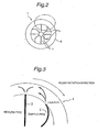
- supply pipes 2 are opened in a direction opposite to the direction of rotation of the filler 1 to cause turbulence in the flow of liquid in the filler 1, thereby enabling the stirring effect to be enhanced.
- the return pipes 3 may be opened perpendicularly to the circumferential direction as shown in Figs. 2 and 3 . Alternatively, the return pipes 3 may be opened at a certain angle to the circumferential direction to cause turbulence in the flow of beverage.
- the return pipes 3 may also be opened in the same direction as the beverage flow direction so as not to produce a turbulent flow.
- each return pipe 3 be provided at a position where the liquid is uniform in view of the properties of the beverage; for example, in the vicinity of the inlet opening of a supply pipe 2 from which the liquid flows into the filler 1.
- the opening of each return pipe 3 is preferably provided in the neighborhood of a stirring member.
- the liquid is constantly circulated and thus stirred in the filler tank. If stirring members are used, the liquid can be stirred even more efficiently. Particularly, when the filling operation by the filler stops, although the liquid is continuously circulated, stirring may become insufficient because the turning of the filler and the filling operation are suspended. In such a case, the use of stirring members makes it possible to push down a solid component that is likely to surface and to allow a readily settling component to rise up. Therefore, a liquid containing a solid component can be kept more uniform. In this case, stirring members capable of pushing down or up in the liquid may be used. For example, as shown in Fig.
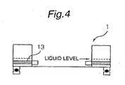
- stirring members 13 each have a parallelepiped configuration with a thickness of 2 mm to 5 mm and a width sufficient for the stirring member 13 to cross the inside of the filler tank horizontally so that the stirring member 13 can be secured at one lateral end thereof to the outer surface of the inner periphery of the filler tank and at the other lateral end thereof to the inner surface of the outer periphery of the filler tank.
- the length of the stirring member 13 is, for example, about 70% of the depth from the liquid surface.
- the stirring member 13 has an angle of about 20 to 40 degrees with respect to the horizontal plane.
- the configuration of the stirring members is not necessarily limited to being rectangular parallelepiped.
- stirring members having a streamline, elliptic or oval shape, a triangular prism shape, or a quadrangular prism shape with a trapezoid section. It should be noted, however, that the configuration of the stirring members is not necessarily limited to these. It is essential only that the stirring members should be capable of pushing down or up in the liquid. The use of such stirring members allows a liquid containing a solid component to be kept even more uniform when it is circulated throughout the path. Hence, it is possible to rapidly resume the filling operation after suspension of the filler.
- Fig. 5 schematically shows the general arrangement of a liquid filling apparatus having a circulation path according to another embodiment of the present invention.
- constituent elements that are substantially the same as those shown in the foregoing embodiment are denoted by the same reference numerals with a suffix "a" added.
- a liquid filled by this filling apparatus is prepared in a preparation tank (not shown) and delivered to a cushion tank 5a where it is stored. It should be noted that in this embodiment a high-temperature liquid is filled, but the liquid as supplied to the cushion tank 5a is at normal temperature.
- the liquid stored in the cushion tank 5a is supplied to a filling liquid tank, i.e. a filler tank 4a, of a filler 1a through a supply line 14a by the operation of a supply pump 10a serving as a liquid supply device.
- the supply line 14a is provided with a heater (heat exchanger) 7a as a heating device.
- the liquid from the cushion tank 5a is heated to a predetermined temperature for sterilization by the heater 7a. After being sterilized in this way, the liquid is delivered to the filler tank 4a.
- the supply pump 10a constantly delivers a fixed amount of liquid.
- the supply line 14a is connected to the filler tank 4a of the filler 1a through a rotary joint 16a. As shown in Fig. 6 , the filler tank 4a has an annular configuration. The supply line 14a is connected to the filler tank 4a through a plurality (3 in this embodiment) of circumferentially equally spaced supply pipes 2a.
- the filler tank 4a is further connected with a return line 15a through a plurality (3 in this embodiment) of return pipes 3a in the same way as the supply line 14a.
- the supply pipes 2a of the supply line 14a and the return pipes 3a of the return line 15a are equally spaced.
- the supply and return pipes 2a and 3a are arranged alternately in the circumferential direction.
- the return line 15a connects between the filler tank 4a of the filler 1a and the cushion tank 5a through the rotary joint 16a.
- the cushion tank 5a, the supply line 14a, the filler tank 4a and the return line 15a form in combination a circulation path.
- the return line 15a is provided with a discharge pump 11a serving as a device that returns the liquid from the filler tank 4a to the cushion tank 5a.
- the return line 15a is further provided with a cooler (heat exchanger) 12a.
- the discharge pump 11a By the operation of the discharge pump 11a, the liquid in the filler tank 4a is delivered to the cooler 12a where it is cooled before being returned to the cushion tank 5a.
- the amount of liquid delivered by the discharge pump 11a can be controlled. The amount of liquid delivered is controlled according to a signal from a level sensor 22a (described later).
- the filler tank 4a of the filler 1a has a plurality of filling devices (filling valves) 17a provided on the outer periphery thereof at equal spacings in the circumferential direction.
- the filling liquid supplied into the filler tank 4a through the supply line 14a is filled into containers (not shown) through the filling valves 17a.
- the filler tank 4a is provided with a level sensor 22a to detect the amount of liquid in the filler tank 4a.
- a detection signal from the level sensor 22a is transmitted to a controller 23a.
- a command from the controller 23a controls the amount of liquid delivered by the discharge pump 11a.
- a liquid to be filled into containers is prepared in a preparation tank (not shown) and delivered into the cushion tank 5a where it is stored. At this time, the liquid is at normal temperature.
- the liquid in the cushion tank 5a is delivered to the heater 7a by the drive of the supply pump 10a. After being heated to a predetermined temperature and thus sterilized in the heater 7a, the liquid is supplied to the filler tank 4a of the filler 1a.
- the level sensor 22a provided in the filler tank 4a constantly detects the amount of filling liquid in the filler tank 4a.
- the controller 23a controls the amount of liquid delivered by the discharge pump 11a according to the value of liquid quantity detected by the level sensor 22a.
- the liquid supplied into the filler tank 4a is filled into containers through the filling valves 17a, and a larger amount of liquid than is needed for filling is supplied to the filler tank 4a. Meanwhile, the filling liquid in the filler tank 4a is returned to the cushion tank 5a through the cooler 12a by the operation of the discharge pump 11a.
- the filling liquid from the cushion tank 5a constantly circulates through the supply line 14a, the heater 7a, the supply pump 10a, the supply pipes 2a, the filler tank 4a, the return pipes 3a, the discharge pump 11a, the cooler 12a and the return line 15a.
- the supply pump 10a constantly supplies a fixed amount of liquid to the filler tank 4a, whereas the discharge pump 11a returns a fixed amount of filling liquid to the cushion tank 5a according to the amount of liquid filled from the filling valves 17a.
- the amount of liquid in the filler tank 4a is increased by controlling the discharge pump 11a according to the value of liquid quantity detected by the level sensor 22a, thereby adjusting the amount of liquid in the filler tank 4a.
- the controller 23a judges that the filler 1a has stopped operating, and controls the discharge pump 11a so that the same amount of filling liquid as supplied from the supply pump 10a is returned from the filler tank 4a. For example, let us assume that during normal operation, the liquid is supplied from the supply pump 10a at a rate of 250 l /m, and the liquid is filled into containers at a rate of 200 1/m, and that the liquid is returned to the cushion tank 5a at a rate of 50 1/m by the discharge pump 11a. On this assumption, if the filler 1a stops operating, no liquid is filled into containers.
- the capacity of the discharge pump 11a is increased so that the liquid is returned to the cushion tank 5a at a rate of 250 l /m that is the same as the rate (250 l /m) of supply from the supply pump 10a.
- the capacity of the supply pump 10a may be reduced so that the supply pump 10a supplies the liquid at a rate of 50 l /m that is the same as the rate (50 l /m) at which the liquid is returned by the discharge pump 11a.
- the control may be effected such that the capacity of the supply pump 10a is reduced to 100 l /m, whereas the capacity of the discharge pump 11a is increased to 100 l /m.
- the filling liquid refluxed from the filler tank 4a is cooled through the cooler 12a before being returned to the cushion tank 5a.
- the temperature in the cushion tank 5a rises undesirably. Consequently, when the liquid from the cushion tank 5a is thereafter supplied through the heater 7a, the liquid temperature undesirably further rises in excess of a set temperature. Therefore, the liquid refluxed from the cushion tank 5a is cooled by the cooler 12a to a temperature substantially equal to the temperature of the liquid stored in the cushion tank 5a.
- the amount of liquid that has to be blown when the operation is resumed is extremely small (it is only necessary to blow a very small amount of liquid remaining in the passage extending from the filler tank 4a to the filling valves 17a).
- the loss of filling liquid can be minimized.
- the discharge pump 11a is controlled to adjust the amount of liquid returned from the filler tank 4a, it should be noted that the adjustment of the amount of liquid returned is not necessarily limited to that effected by controlling the discharge pump 11a, but may be made, for example, by using a control valve additionally provided. It is also possible to control the amount of liquid delivered from the supply pump 10a on the supply side.
Description
- The present invention relates to a method of filling a liquid and also relates to an apparatus for use in carrying out the method. The present invention also pertains to a liquid filling method and apparatus capable of rapidly resuming the operation of a filling line after suspension while preventing deterioration of a filling liquid of high temperature. A method and an apparatus of the kind are known from
patent documents US 3515180A andDE 20105716U1 discussed hereinafter. - In an ordinary beverage production line, the supply of a beverage from a beverage storage tank to a beverage filling machine (hereinafter referred to as simply "filler") is a flow in one direction. If the filler stops operating due to, for example, some problem with a bottle and becomes unable to accept the beverage, a sensor detects this situation and stops delivery of liquid to the filler. When the liquid delivery stops, the beverage in a filler bowl, i.e. a filler tank, cools naturally or is cooled with an aseptic air flow. Therefore, if the production line stops for more than a certain period of time, the liquid temperature becomes lower than the sterilizing temperature of containers, caps, etc. In this case, it is necessary, when resuming the operation of the filling line, to discard the cooled liquid in the filler tank and to blow the heated beverage (i.e. it is necessary to supply the heated beverage to the filler and to discharge it from filling nozzles) in order to raise the temperature of the filler tank and the filling nozzles. Accordingly, there are losses of beverage due to discard and blowing. To reduce these losses of beverage, some methods have been developed; for example, a method wherein when the filling line stops, the beverage in the filler is recovered and returned to the product tank in which the beverage is reheated before being filled [Japanese Patent Unexamined Publication (KOKAI) No.
2001-72189 2002-337988 -
US 3515180 A relates to a method and an apparatus for filling containers with beverage using a packed line principle. -
DE 201 05 716 U1 relates to a filling device andFR 2 165 430 A5 - There has also been developed a system in which a liquid is constantly circulated through a filling line including a product storage tank, a heat sterilizer, and filling valves [Japanese Patent Unexamined Publication (KOKAI) No.
Sho 59-74097 Hei 2-27236 - Meanwhile, when filling a beverage containing a solid component, it is difficult to keep the solid component content of the filling liquid constant. Therefore, in one type of filling method, the solid component and the liquid are filled separately from each other. In this case, however, the apparatus becomes large in size and high in cost, and it is difficult to add the apparatus to existing equipment. Accordingly, there has been developed an apparatus in which an additional line is provided to allow the beverage in the filler to circulate through a path in the neighborhood of the filler [Japanese Patent Unexamined Publication (KOKAI) No.
Hei 6-293302 - When the filling process is suspended for any reason, the flow of liquid in and out of the filler stops, and the rotating motion of the filler also stops. Consequently, the beverage in the filler stops flowing. If there is no flow of beverage in the filler, the solid component contained in the beverage settles by gravity or surfaces, resulting in separation of the solid component and the liquid. If the filling process is resumed in this state, the solid component content changes as follows. For example, at the beginning of the resumed filling process, the solid component content is high because it has settled. Thereafter, the solid component content becomes extremely low, and as time goes by, it returns to normal and becomes uniform. In this case, the solid component content varies among products undesirably. Accordingly, it has been demanded to develop a method capable of filling with a constant solid component content when the operation of the production line is resumed after suspension.
- The present invention was made in view of the above-described problems with the conventional liquid filling method. An object of the present invention is to provide a liquid filling method and apparatus which is capable of reducing the lead time when the filling operation is resumed, as well as being capable of suppressing the deterioration of aroma and taste of the filling liquid.
- Another object of the present invention is to provide a liquid filling method and apparatus capable of keeping the solid component content constant when filling a liquid containing a solid component.
- A further object of the present invention is to provide a liquid filling method and apparatus capable of preventing lowering of the temperature of a high-temperature liquid to be filled, thereby reducing the lead time when the filling operation is resumed, and achieving energy saving.
- A still further object of the present invention is to provide a liquid filling method and apparatus having a circulation path capable of minimizing the filling liquid loss when filling a liquid of high temperature.
- According to the present invention, there is provided a liquid filling method wherein a liquid is delivered from a storage tank into a filler tank of a filler, and the liquid is filled into containers by the filler. In the liquid filling method, the liquid in said filler tank is returned through a return piping attached to said filler tank and refluxed to said storage tank through a reflux path so that the liquid circulates throughout the entire filling line extending from said storage tank to said filler, characterized in that an amount of liquid in the filler tank is detected by means of a detecting device, and at least one of an amount of liquid supplied to said filler tank and an amount of liquid returned from said filler tank is controlled according to a detected value from said detecting device, wherein during filling by said filler, the amount of liquid supplied to said filler tank is larger than the amount of liquid returned from said filler tank, and during suspension of filling, the amount of liquid supplied to said filler tank is equal to the amount of liquid returned from said filler tank. According to the present invention, there is provided a liquid filling apparatus that fills a liquid into containers. The apparatus includes a liquid filling line having a storage tank that stores the liquid and a filler that fills said liquid into the containers, wherein the liquid in a filler tank is returned through a return piping attached to the filler tank to the entire liquid filling line so that said liquid constantly circulates throughout said liquid filling line, characterized in that the liquid filling apparatus further includes: a detecting device that detects an amount of liquid in said filler tank; and
a controller that controls at least one of an amount of liquid supplied to said filler tank and an amount of liquid returned from said filler tank according to a detected value from said detecting device, wherein during filling by said filler, the amount of liquid supplied to said filler tank is larger than the amount of liquid returned from said filler tank, and during suspension of filling, the amount of liquid supplied to said filler tank is equal to the amount of liquid returned from said filler tank. - According to the present invention, an excess of liquid in the filler tank can be circulated throughout the filling line. Consequently, the liquid can constantly circulate through the line. Therefore, it is possible to suppress lowering of the temperature of the liquid in the filler tank even during suspension of the operation of the line and hence possible to resume production after the suspension of the line operation substantially without lead time. In filling of a liquid containing a solid component, uniform conditions can be maintained throughout the production line. Therefore, it is possible to produce products with no variations in the solid component content, regardless of whether the filling temperature is normal or low.
- A liquid filling method is discussed wherein a liquid delivered from a storage tank is heat-sterilized before being delivered into a filler tank of a filler, and the liquid is filled into containers by the filler. The liquid filling method is characterized in that the liquid in said filler tank is returned through a return piping attached to said filler tank and refluxed to said storage tank through a reflux path so that the liquid circulates throughout the entire filling line extending from said storage tank to said filler, wherein the liquid flowing through said reflux path to said storage tank is cooled. A liquid filling apparatus is discussed that fills a liquid into containers. The liquid filling apparatus includes a liquid filling line having a storage tank that stores the liquid, a heat sterilizer that heat-sterilizes said liquid, and a filler that fills said liquid into the containers, wherein the liquid in a filler tank is returned through return piping attached to said filler tank to the entire liquid filling line so that said liquid circulates throughout said liquid filling line, said apparatus further including a cooling device that cools the liquid flowing through said reflux path.
- According to the above-described method and apparatus , a part of liquid in the filler tank is constantly refluxed to the storage tank through the reflux path, and the liquid flowing through the reflux path is cooled by a cooling process using a cooling device. By this process, the liquid left unused for filling can be circulated throughout the liquid filling line, regardless of whether filling is being performed or not, and the filler temperature can be always kept at high level. Moreover, the uniformity of the liquid in the line can be guaranteed. Provision of the process for cooling the liquid before it is refluxed to the storage tank prevents quality deterioration of the liquid, which might otherwise occur when the liquid is kept at high temperature for a long period of time. It is also possible to keep the storage tank temperature constant and to stabilize the heat sterilization process.
- The above-described liquid filling method may be as follows. The amount of liquid in the filler tank is detected by means of a detecting device, and at least one of the amount of liquid supplied to the filler tank and the amount of liquid returned from the filler tank is controlled according to a detected value from the detecting device. In this case, the liquid quantity may be controlled as follows. During filling by the filler, the amount of liquid supplied to the filler tank may be larger than the amount of liquid returned from the filler tank. During suspension of filling, the amount of liquid supplied to the filler tank may be equal to the amount of liquid returned from the filler tank.
- The liquid filling apparatus has a detecting device that detects the amount of liquid in the filler tank, and a controller that controls at least one of the amount of liquid supplied to the filler tank and the amount of liquid returned from the filler tank according to a detected value from the detecting device. The liquid quantity is controlled as follows. During filling by the filler, the amount of liquid supplied to the filler tank is larger than the amount of liquid returned from the filler tank. During suspension of filling, the amount of liquid supplied to the filler tank is equal to the amount of liquid returned from the filler tank.
-
-
Fig. 1 is a schematic general view of a liquid filling apparatus for carrying out the invention of this application. -
Fig. 2 is a plan view of a filler. -
Fig. 3 is an enlarged view of a part ofFig. 2 , showing an inlet opening and a return opening in the filler. -
Fig. 4 is a schematic sectional view of a filler tank equipped with stirring members. -
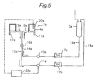
Fig. 5 is a schematic general view showing another embodiment of the liquid filling apparatus according to the invention of this application. -
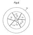
Fig. 6 is a diagram showing supply and return pipes attached to a filler tank of the liquid filling apparatus shown inFig. 5 . - Embodiments of the present invention will be described below with reference to the accompanying drawings and with regard to a beverage filling apparatus that fills a beverage as a filling liquid.
-
Fig. 1 shows an example of the general arrangement of a liquid filling apparatus used to carry out the invention of this application. A beverage stored in a beverage tank 5 is delivered through a liquid delivery pump 6 provided in asupply line 14 to a heat sterilizer 7 in which the beverage is heat-sterilized. The temperature of heat sterilization differs according to the kind of beverage. For example, tea is heat-sterilized at a temperature of about 140ºC. A beverage containing fruit flesh is heat-sterilized at a temperature of around 90ºC. This process is unnecessary in the case of normal or low-temperature filling. The heat-sterilized beverage is cooled by a cooling device 8 to a temperature suitable for filling, e.g. to a temperature of about 82ºC to 87ºC if containers for filling are PET (polyethylene terephthalate) bottles. This process may be omitted in the case of normal or low-temperature filling. The cooled liquid is deaerated, for example, in adeaeration tank 9. This is done for the purpose of preventing foaming and also preventing quality degradation due to oxidation. The deaeration process may be omitted in the case of normal or low-temperature filling. - Next, the beverage is delivered in the direction of the arrow A through a
pump 10 serving as a delivery device and introduced into afiller tank 4 of afiller 1. During a filling operation, the beverage is filled into containers, e.g. PET bottles, by thefiller 1 having a publicly known structure. At this time, the liquid level in thefiller tank 4 is monitored by means of a level meter. If overflow occurs, the beverage is recovered throughreturn pipes 3 and delivered by a discharge pump 11 provided in areturn line 15 in the direction of the arrow B to acooling device 12 in which the beverage is cooled down to approximately normal temperature. The cooled beverage returns to the beverage tank 5. - By circulating as stated above, the beverage continuously flows through the line and is stirred effectively so that the solid component will not settle or surface. Accordingly, uniform filling can be performed. In addition, the solid component content of the beverage will not vary when the filling process is resumed after suspension of the operation of the line. Further, because lowering of the filler temperature can be prevented, it is possible to rapidly resume the filling process after suspension of the line operation. It is also possible to reduce waste loss due to blowing of beverage (discharge from the filler). Further, because the return liquid is cooled, it is possible to prevent quality degradation that might otherwise occur when the beverage is constantly exposed to high temperature. In addition, it is possible to keep the temperature of the beverage tank 5 substantially constant and hence it is possible to stabilize the subsequent process of heat sterilization. The cooling process may be omitted in the case of normal or low-temperature filling.
- In order to reflux the beverage from the filler, the filler tank is provided with return pipes. Each return pipe is connected to the filler tank by welding or by a publicly known method in a leak-free state with a packing or the like interposed therebetween. The number of return pipes is typically about 2 to 4 but may be larger than that. If a double pipe is used for a combination of a supply pipe and a return pipe, piping can be formed from a single system of pipes and thus simplified. In such a case, the feed liquid and the return liquid, which are at high temperature, are adjacent to each other across the pipe wall and hence capable of effectively keeping each other warm. As shown in
Figs. 2 and 3 ,supply pipes 2 are opened in a direction opposite to the direction of rotation of thefiller 1 to cause turbulence in the flow of liquid in thefiller 1, thereby enabling the stirring effect to be enhanced. Thereturn pipes 3 may be opened perpendicularly to the circumferential direction as shown inFigs. 2 and 3 . Alternatively, thereturn pipes 3 may be opened at a certain angle to the circumferential direction to cause turbulence in the flow of beverage. Thereturn pipes 3 may also be opened in the same direction as the beverage flow direction so as not to produce a turbulent flow. It is preferable that the opening of eachreturn pipe 3 be provided at a position where the liquid is uniform in view of the properties of the beverage; for example, in the vicinity of the inlet opening of asupply pipe 2 from which the liquid flows into thefiller 1. In a case where stirring members are additionally provided, the opening of eachreturn pipe 3 is preferably provided in the neighborhood of a stirring member. - In the present invention, the liquid is constantly circulated and thus stirred in the filler tank. If stirring members are used, the liquid can be stirred even more efficiently. Particularly, when the filling operation by the filler stops, although the liquid is continuously circulated, stirring may become insufficient because the turning of the filler and the filling operation are suspended. In such a case, the use of stirring members makes it possible to push down a solid component that is likely to surface and to allow a readily settling component to rise up. Therefore, a liquid containing a solid component can be kept more uniform. In this case, stirring members capable of pushing down or up in the liquid may be used. For example, as shown in
Fig. 4 , stirringmembers 13 each have a parallelepiped configuration with a thickness of 2 mm to 5 mm and a width sufficient for the stirringmember 13 to cross the inside of the filler tank horizontally so that the stirringmember 13 can be secured at one lateral end thereof to the outer surface of the inner periphery of the filler tank and at the other lateral end thereof to the inner surface of the outer periphery of the filler tank. The length of the stirringmember 13 is, for example, about 70% of the depth from the liquid surface. The stirringmember 13 has an angle of about 20 to 40 degrees with respect to the horizontal plane. The configuration of the stirring members is not necessarily limited to being rectangular parallelepiped. For example, it is also possible to use stirring members having a streamline, elliptic or oval shape, a triangular prism shape, or a quadrangular prism shape with a trapezoid section. It should be noted, however, that the configuration of the stirring members is not necessarily limited to these. It is essential only that the stirring members should be capable of pushing down or up in the liquid. The use of such stirring members allows a liquid containing a solid component to be kept even more uniform when it is circulated throughout the path. Hence, it is possible to rapidly resume the filling operation after suspension of the filler. -
Fig. 5 schematically shows the general arrangement of a liquid filling apparatus having a circulation path according to another embodiment of the present invention. In this embodiment, constituent elements that are substantially the same as those shown in the foregoing embodiment are denoted by the same reference numerals with a suffix "a" added. A liquid filled by this filling apparatus is prepared in a preparation tank (not shown) and delivered to acushion tank 5a where it is stored. It should be noted that in this embodiment a high-temperature liquid is filled, but the liquid as supplied to thecushion tank 5a is at normal temperature. - The liquid stored in the
cushion tank 5a is supplied to a filling liquid tank, i.e. afiller tank 4a, of afiller 1a through asupply line 14a by the operation of asupply pump 10a serving as a liquid supply device. Thesupply line 14a is provided with a heater (heat exchanger) 7a as a heating device. The liquid from thecushion tank 5a is heated to a predetermined temperature for sterilization by theheater 7a. After being sterilized in this way, the liquid is delivered to thefiller tank 4a. It should be noted that in this embodiment thesupply pump 10a constantly delivers a fixed amount of liquid. - The
supply line 14a is connected to thefiller tank 4a of thefiller 1a through a rotary joint 16a. As shown inFig. 6 , thefiller tank 4a has an annular configuration. Thesupply line 14a is connected to thefiller tank 4a through a plurality (3 in this embodiment) of circumferentially equally spacedsupply pipes 2a. - The
filler tank 4a is further connected with areturn line 15a through a plurality (3 in this embodiment) ofreturn pipes 3a in the same way as thesupply line 14a. Thesupply pipes 2a of thesupply line 14a and thereturn pipes 3a of thereturn line 15a are equally spaced. The supply and returnpipes return line 15a connects between thefiller tank 4a of thefiller 1a and thecushion tank 5a through the rotary joint 16a. Thecushion tank 5a, thesupply line 14a, thefiller tank 4a and thereturn line 15a form in combination a circulation path. Thereturn line 15a is provided with adischarge pump 11a serving as a device that returns the liquid from thefiller tank 4a to thecushion tank 5a. Thereturn line 15a is further provided with a cooler (heat exchanger) 12a. By the operation of thedischarge pump 11a, the liquid in thefiller tank 4a is delivered to the cooler 12a where it is cooled before being returned to thecushion tank 5a. It should be noted that in this embodiment the amount of liquid delivered by thedischarge pump 11a can be controlled. The amount of liquid delivered is controlled according to a signal from alevel sensor 22a (described later). - The
filler tank 4a of thefiller 1a has a plurality of filling devices (filling valves) 17a provided on the outer periphery thereof at equal spacings in the circumferential direction. The filling liquid supplied into thefiller tank 4a through thesupply line 14a is filled into containers (not shown) through the fillingvalves 17a. - The
filler tank 4a is provided with alevel sensor 22a to detect the amount of liquid in thefiller tank 4a. A detection signal from thelevel sensor 22a is transmitted to acontroller 23a. A command from thecontroller 23a controls the amount of liquid delivered by thedischarge pump 11a. - The operation of the filling system arranged as stated above will be described below. A liquid to be filled into containers is prepared in a preparation tank (not shown) and delivered into the
cushion tank 5a where it is stored. At this time, the liquid is at normal temperature. The liquid in thecushion tank 5a is delivered to theheater 7a by the drive of thesupply pump 10a. After being heated to a predetermined temperature and thus sterilized in theheater 7a, the liquid is supplied to thefiller tank 4a of thefiller 1a. Thelevel sensor 22a provided in thefiller tank 4a constantly detects the amount of filling liquid in thefiller tank 4a. Thecontroller 23a controls the amount of liquid delivered by thedischarge pump 11a according to the value of liquid quantity detected by thelevel sensor 22a. - During normal operation, the liquid supplied into the
filler tank 4a is filled into containers through the fillingvalves 17a, and a larger amount of liquid than is needed for filling is supplied to thefiller tank 4a. Meanwhile, the filling liquid in thefiller tank 4a is returned to thecushion tank 5a through the cooler 12a by the operation of thedischarge pump 11a. As shown inFig. 5 , the filling liquid from thecushion tank 5a constantly circulates through thesupply line 14a, theheater 7a, thesupply pump 10a, thesupply pipes 2a, thefiller tank 4a, thereturn pipes 3a, thedischarge pump 11a, the cooler 12a and thereturn line 15a. In this embodiment, thesupply pump 10a constantly supplies a fixed amount of liquid to thefiller tank 4a, whereas thedischarge pump 11a returns a fixed amount of filling liquid to thecushion tank 5a according to the amount of liquid filled from the fillingvalves 17a. - During suspension of the operation of the
filler 1a, filling from the fillingvalves 17a into containers is not carried out. Therefore, if the same amount of filling liquid as during normal operation is discharged from thefiller tank 4a, the amount of liquid in thefiller tank 4a will gradually increase. In this embodiment, however, the amount of liquid discharged from thefiller tank 4a is increased by controlling thedischarge pump 11a according to the value of liquid quantity detected by thelevel sensor 22a, thereby adjusting the amount of liquid in thefiller tank 4a. More specifically, if the detected value from thelevel sensor 22a exceeds a predetermined upper limit, thecontroller 23a judges that thefiller 1a has stopped operating, and controls thedischarge pump 11a so that the same amount of filling liquid as supplied from thesupply pump 10a is returned from thefiller tank 4a. For example, let us assume that during normal operation, the liquid is supplied from thesupply pump 10a at a rate of 250 l/m, and the liquid is filled into containers at a rate of 200 1/m, and that the liquid is returned to thecushion tank 5a at a rate of 50 1/m by thedischarge pump 11a. On this assumption, if thefiller 1a stops operating, no liquid is filled into containers. Therefore, the capacity of thedischarge pump 11a is increased so that the liquid is returned to thecushion tank 5a at a rate of 250 l/m that is the same as the rate (250 l/m) of supply from thesupply pump 10a. It should be noted that when thefiller 1a stops operating, the capacity of thesupply pump 10a may be reduced so that thesupply pump 10a supplies the liquid at a rate of 50 l/m that is the same as the rate (50 l/m) at which the liquid is returned by thedischarge pump 11a. The control may be effected such that the capacity of thesupply pump 10a is reduced to 100 l/m, whereas the capacity of thedischarge pump 11a is increased to 100 l/m. - The filling liquid refluxed from the
filler tank 4a is cooled through the cooler 12a before being returned to thecushion tank 5a. In the case of filling a high-temperature liquid, if the liquid refluxed from thefiller tank 4a is returned to thecushion tank 5a as it is, the temperature in thecushion tank 5a rises undesirably. Consequently, when the liquid from thecushion tank 5a is thereafter supplied through theheater 7a, the liquid temperature undesirably further rises in excess of a set temperature. Therefore, the liquid refluxed from thecushion tank 5a is cooled by the cooler 12a to a temperature substantially equal to the temperature of the liquid stored in thecushion tank 5a. - Accordingly, the amount of liquid that has to be blown when the operation is resumed is extremely small (it is only necessary to blow a very small amount of liquid remaining in the passage extending from the
filler tank 4a to the fillingvalves 17a). Thus, the loss of filling liquid can be minimized. Although in this embodiment thedischarge pump 11a is controlled to adjust the amount of liquid returned from thefiller tank 4a, it should be noted that the adjustment of the amount of liquid returned is not necessarily limited to that effected by controlling thedischarge pump 11a, but may be made, for example, by using a control valve additionally provided. It is also possible to control the amount of liquid delivered from thesupply pump 10a on the supply side. -
- The present invention offers the following advantageous effects.
- (a) Even when the filling operation of the filler stops, because the beverage is constantly circulated, the beverage in the filler is stirred. Accordingly, the uniformity of the beverage is maintained throughout the filling line.
- (b) A solid component will not settle or surface, and it is possible to keep the solid component content constant when filling a beverage containing a solid component.
- (c) Because the liquid is circulated throughout the entire filling line, the temperature of the filler tank and that of the beverage in the filler tank can be prevented from lowering.
- (d) The circulation allows the liquid in the filler tank to flow constantly and hence makes it possible to prevent adhesion of the pulp content to the inner surface of the filler tank. Further, because the liquid circulates, it is possible to increase the velocity of washing flow in the filler tank upon completion of the filling operation and hence it is possible to improve the capability to wash away the pulp content.
- (e) Because the return liquid is cooled, it is possible to prevent quality degradation that might otherwise occur when the beverage is constantly exposed to high temperature.
- (f) When a beverage containing a solid component is filled at high temperature, lowering of the filler temperature can be prevented by circulation of the beverage throughout the entire circulation path extending from the storage tank to the filler. At the same time, stirring induced by the circulation causes mixing of the solid component with the liquid component. Thus, the filling operation can be started rapidly upon resumption of the operation of the filling line.
- (g) The circulation eliminates stagnation of a beverage liquid. Consequently, the path from the heater through the filler to a point immediately upstream of the cooler is always kept at high temperature. Thus, it is possible to prevent propagation of microorganisms in this part of the path.
- (h) Even in normal or low-temperature filling of a beverage containing a solid component, the solid component and the liquid component are always mixed together by the circulation of the beverage throughout the entire filling line extending from the storage tank to the filler. Therefore, there will occur no separation between the solid component and the liquid components in the filler or the piping. Stirring taking place throughout the path from the storage tank to the filler allows the beverage to be stirred even more uniformly than stirring performed only around the filler as in the conventional technique. Accordingly, the uniformity of products is further improved.
- (i) The amount of liquid in the filler tank is detected by means of a detecting device, and at least one of the amount of liquid supplied to the filler tank and the amount of liquid returned from the filler tank is controlled by means of a controller according to a detected value from the detecting device. Accordingly, it is possible to minimize the amount of liquid that has to be blown in the heat-up process when the filling operation is resumed.
Claims (4)
- A liquid filling method wherein a liquid is delivered from a storage tank (5) into a filler tank (4) of a filler (1), and said liquid is filled into containers by said filler (1), wherein the liquid in said filler tank (4) is returned through a return piping (3) attached to said filler tank (4) and refluxed to said storage tank (5) through a reflux path (15) so that the liquid circulates throughout the entire filling line extending from said storage tank to said filler (1), characterized in that an amount of liquid in the filler tank (4) is detected by means of a detecting device (22a), and at least one of an amount of liquid supplied to said filler tank (4) and an amount of liquid returned from said filler tank (4) is controlled according to a detected value from said detecting device (22a), wherein during filling by said filler (1), the amount of liquid supplied to said filler tank (4) is larger than the amount of liquid returned from said filler tank (4), and during suspension of filling, the amount of liquid supplied to said filler tank (4) is equal to the amount of liquid returned from said filler tank (4).
- A liquid filling method according to claim 1, wherein said liquid is a beverage containing a solid component.
- A liquid filling apparatus that fills a liquid into containers, said apparatus including a liquid filling line having a storage tank (5) that stores the liquid and a filler (1) that fills said liquid into the containers, wherein the liquid in a filler tank (4) is returned through a return piping (3) attached to the filler tank (4) to the entire liquid filling line so that said liquid constantly circulates throughout said liquid line, characterized in that the liquid filling apparatus further includes:a detecting device (22a) that detects an amount of liquid in said filler tank (4); anda controller (23a) that controls at least one of an amount of liquid supplied to said filler tank (4) and an amount of liquid returned from said filler tank (4) according to a detected value from said detecting device, wherein during filling by said filler (1), the amount of liquid supplied to said filler tank (4) is larger than the amount of liquid returned from said filler tank (4), and during suspension of filling, the amount of liquid supplied to said filler tank (4) is equal to the amount of liquid returned from said filler tank (4).
- A liquid filling apparatus according to claim 3 wherein said liquid is a beverage containing a solid component.
Applications Claiming Priority (3)
| Application Number | Priority Date | Filing Date | Title |
|---|---|---|---|
| JP2002361443 | 2002-12-12 | ||
| JP2002361443 | 2002-12-12 | ||
| PCT/JP2003/015866 WO2004052770A1 (en) | 2002-12-12 | 2003-12-11 | Liquid filling method and liquid filling device |
Publications (3)
| Publication Number | Publication Date |
|---|---|
| EP1598308A1 EP1598308A1 (en) | 2005-11-23 |
| EP1598308A4 EP1598308A4 (en) | 2011-03-02 |
| EP1598308B1 true EP1598308B1 (en) | 2013-05-29 |
Family
ID=32501045
Family Applications (1)
| Application Number | Title | Priority Date | Filing Date |
|---|---|---|---|
| EP03778810.6A Expired - Lifetime EP1598308B1 (en) | 2002-12-12 | 2003-12-11 | Liquid filling method and liquid filling device |
Country Status (7)
| Country | Link |
|---|---|
| US (1) | US7694858B2 (en) |
| EP (1) | EP1598308B1 (en) |
| JP (2) | JP4468181B2 (en) |
| CN (1) | CN100457600C (en) |
| ES (1) | ES2413486T3 (en) |
| TW (1) | TW200420490A (en) |
| WO (1) | WO2004052770A1 (en) |
Families Citing this family (18)
| Publication number | Priority date | Publication date | Assignee | Title |
|---|---|---|---|---|
| DE102007024106B4 (en) * | 2007-05-22 | 2009-12-03 | Khs Ag | filling system |
| DE102007058047A1 (en) * | 2007-11-30 | 2009-06-10 | Khs Ag | Method and device for filling liquids |
| DE102008049937A1 (en) | 2008-10-02 | 2010-04-29 | Khs Ag | Device and method for treating containers |
| DE102008056597A1 (en) * | 2008-11-10 | 2010-05-12 | Krones Ag | Hot filling plant with heat recovery |
| SE534448C2 (en) * | 2010-04-13 | 2011-08-23 | Tetra Laval Holdings & Finance | Method and apparatus for recovering energy during hot filling of a liquid food product |
| DE102010033169A1 (en) * | 2010-08-03 | 2012-02-09 | Khs Gmbh | Method and plant for filling containers with a liquid product |
| DE102011007787A1 (en) * | 2011-04-20 | 2014-01-16 | Krones Aktiengesellschaft | Apparatus and method for treating a liquid food product |
| ITMI20120281A1 (en) * | 2012-02-24 | 2013-08-25 | I M A Ind Macchine Automatic He S P A | ZERO DOSAGE PROCEDURE AND FILLING EQUIPMENT FOR FILLING LIQUID CONTAINERS |
| PL2897871T3 (en) | 2012-09-24 | 2019-08-30 | Nestec S.A. | Methods and systems for coordination of aseptic sterilization and aseptic package filling rate |
| WO2014103787A1 (en) * | 2012-12-27 | 2014-07-03 | 大日本印刷株式会社 | Beverage filling device and pasteurization method for same |
| ES2809485T3 (en) * | 2013-03-22 | 2021-03-04 | Pepsico Inc | Container filling system |
| JP6442359B2 (en) | 2015-05-15 | 2018-12-19 | 株式会社Screenホールディングス | Liquid filling method and filler layer forming method |
| DE102016217342A1 (en) * | 2016-09-12 | 2018-03-15 | Krones Ag | Filling plant for heat treatment and filling of a liquid |
| JP6521396B2 (en) * | 2017-07-04 | 2019-05-29 | 大日本印刷株式会社 | Aseptic filling system |
| DE102017120322A1 (en) * | 2017-09-04 | 2019-03-07 | Krones Ag | Apparatus and method for filling a container with a filling product |
| EP3659963B1 (en) * | 2018-11-29 | 2021-04-14 | Sidel Participations | Filling plant and method for filling receptacles with a pourable food product |
| DE102019126946A1 (en) * | 2019-10-08 | 2021-04-08 | Krones Aktiengesellschaft | Method and device for hot filling of liquid product |
| CN113501150B (en) * | 2021-07-12 | 2022-12-13 | 楚天科技股份有限公司 | Suspension filling control method, control system and filling system |
Family Cites Families (27)
| Publication number | Priority date | Publication date | Assignee | Title |
|---|---|---|---|---|
| US1654379A (en) * | 1927-06-30 | 1927-12-27 | Matzka Wincenty | Displaying and dispensing apparatus for beverages |
| DE1761313A1 (en) * | 1967-05-10 | 1971-05-13 | Sordi M | Back pressure valve device for a circuit for feeding a machine for the sterile packaging of liquids |
| US3515180A (en) | 1967-07-21 | 1970-06-02 | Automatic Sprinkler Corp | Method and apparatus for filling containers with beverages using a packed line principle |
| CH552537A (en) | 1971-12-15 | 1974-08-15 | Seitz Werke Gmbh | LIQUID FILLING PLANT. |
| JPS5974097A (en) | 1982-10-15 | 1984-04-26 | キング醸造株式会社 | Method and device for filling liquefied material |
| JPH0227236B2 (en) | 1982-11-19 | 1990-06-15 | Mitsubishi Heavy Ind Ltd | EKISHORISOCHI |
| IT1187164B (en) * | 1985-04-24 | 1987-12-16 | Rossi & Catelli Spa | PROCEDURE AND PLANT FOR REDUCING FOOD AND PASTA IN JUICE AND / OR PASTA |
| JPH0333676Y2 (en) * | 1986-03-12 | 1991-07-17 | ||
| DE3629670C1 (en) | 1986-09-01 | 1987-12-17 | Cullmann Handel | Tripod for optical devices |
| JPS6367499U (en) * | 1986-10-22 | 1988-05-06 | ||
| JPH0227236A (en) | 1988-07-18 | 1990-01-30 | Shikoku Keisoku Kogyo Kk | Damage detector for weak pin |
| JP2513276Y2 (en) * | 1990-03-16 | 1996-10-02 | 澁谷工業株式会社 | Stirrer for product liquid in filler bowl |
| JP3416188B2 (en) * | 1993-04-06 | 2003-06-16 | 三菱重工業株式会社 | Filling machine liquid level control device |
| JPH06293302A (en) | 1993-04-07 | 1994-10-21 | Mitsubishi Heavy Ind Ltd | Product liquid stirrer in filler bowl |
| JPH06345191A (en) * | 1993-06-01 | 1994-12-20 | Mitsubishi Heavy Ind Ltd | Filling apparatus |
| CA2128672C (en) * | 1994-07-22 | 2004-10-26 | George Raymond Field | Water cooling apparatus |
| JP3416286B2 (en) | 1994-09-29 | 2003-06-16 | 三菱重工業株式会社 | Cleaning equipment for filling machines |
| US6120824A (en) * | 1995-05-16 | 2000-09-19 | Mendez; Alejandro | Process for the natural aseptic packaging of fruit products and dairy products for extending shelf life without refrigeration |
| CN2264738Y (en) * | 1996-02-14 | 1997-10-15 | 郭清富 | Full-automatic quantifying liquid filler |
| US5908651A (en) * | 1997-11-20 | 1999-06-01 | Tetra Laval Holdings & Finance, Sa | Product recovery system and method |
| US5944071A (en) * | 1998-02-25 | 1999-08-31 | Crown Simplimatic Incorporated | Two chamber filling tank |
| JPH11249466A (en) * | 1998-02-27 | 1999-09-17 | Canon Inc | Fixing method |
| JP4366779B2 (en) * | 1999-09-03 | 2009-11-18 | 澁谷工業株式会社 | Beverage production line |
| US6656423B1 (en) * | 2000-02-07 | 2003-12-02 | Steris Inc. | Sterile water generator |
| CN2430359Y (en) * | 2000-06-09 | 2001-05-16 | 同济医科大学附属同济医院 | Multifunction filling machine for liquid and thick paste |
| DE20105716U1 (en) | 2001-03-30 | 2002-05-29 | Krones Ag | Container filling machine |
| JP3699662B2 (en) | 2001-05-11 | 2005-09-28 | 株式会社アサヒビールエンジニアリング | Liquid high temperature filling equipment |
-
2003
- 2003-12-11 ES ES03778810T patent/ES2413486T3/en not_active Expired - Lifetime
- 2003-12-11 US US10/538,643 patent/US7694858B2/en not_active Expired - Fee Related
- 2003-12-11 WO PCT/JP2003/015866 patent/WO2004052770A1/en active Application Filing
- 2003-12-11 EP EP03778810.6A patent/EP1598308B1/en not_active Expired - Lifetime
- 2003-12-11 JP JP2004558474A patent/JP4468181B2/en not_active Expired - Fee Related
- 2003-12-11 CN CNB200380108689XA patent/CN100457600C/en not_active Expired - Fee Related
- 2003-12-12 TW TW092135276A patent/TW200420490A/en not_active IP Right Cessation
-
2009
- 2009-07-31 JP JP2009179783A patent/JP5149255B2/en not_active Expired - Fee Related
Also Published As
| Publication number | Publication date |
|---|---|
| CN1738762A (en) | 2006-02-22 |
| EP1598308A4 (en) | 2011-03-02 |
| EP1598308A1 (en) | 2005-11-23 |
| ES2413486T3 (en) | 2013-07-16 |
| WO2004052770A1 (en) | 2004-06-24 |
| JP5149255B2 (en) | 2013-02-20 |
| TWI292388B (en) | 2008-01-11 |
| JP2009286497A (en) | 2009-12-10 |
| CN100457600C (en) | 2009-02-04 |
| JP4468181B2 (en) | 2010-05-26 |
| US7694858B2 (en) | 2010-04-13 |
| JPWO2004052770A1 (en) | 2006-04-13 |
| US20060137761A1 (en) | 2006-06-29 |
| TW200420490A (en) | 2004-10-16 |
Similar Documents
| Publication | Publication Date | Title |
|---|---|---|
| EP1598308B1 (en) | Liquid filling method and liquid filling device | |
| US4441406A (en) | Pasteurization apparatus | |
| EP0790781B1 (en) | Process for the pasteurization of liquid contained and tunnel pasteurizer for carrying-out such process | |
| US4490401A (en) | Pasteurization method | |
| US4539903A (en) | Filling apparatus | |
| JP2009537401A (en) | Method and apparatus for controlling foaming of a charge placed in a bottle or equivalent container | |
| TWI304047B (en) | ||
| DK2233010T3 (en) | A method of operating a pasteurizer and pasteurisation | |
| JP2018157815A (en) | Pasteurization plant and method for operating the pasteurizing plant | |
| US4552190A (en) | Filling machines | |
| JP4265357B2 (en) | Filling system | |
| JPH0910286A (en) | Device and method for heating and sterilizing product liquid | |
| JP7250084B2 (en) | Control method of product liquid pipeline pressure | |
| JP3416188B2 (en) | Filling machine liquid level control device | |
| EP1083801B1 (en) | Method and apparatus for the pasteurization of liquid products in a continuous flow | |
| EP4159665A1 (en) | System for dosing an aromatic product into containers | |
| JP4548908B2 (en) | Heating device | |
| JP5090298B2 (en) | Liquid filling equipment and operating method thereof | |
| JPH0819386A (en) | Method and device for pasteurizing content in container | |
| EP3160243B1 (en) | A method for efficiently filling a system with liquid product | |
| JP2700598B2 (en) | Bath-type heating / cooling method and bath-type heating / cooling device for heating or cooling object by liquid circulation | |
| JP2023139666A (en) | Manufacturing line and manufacturing method | |
| JPH10262627A (en) | Sterilizer | |
| KR20230137870A (en) | Liquid food manufacturing equipment | |
| JPS5852090A (en) | Controller for liquid surface of filler |
Legal Events
| Date | Code | Title | Description |
|---|---|---|---|
| PUAI | Public reference made under article 153(3) epc to a published international application that has entered the european phase |
Free format text: ORIGINAL CODE: 0009012 |
|
| 17P | Request for examination filed |
Effective date: 20050708 |
|
| AK | Designated contracting states |
Kind code of ref document: A1 Designated state(s): AT BE BG CH CY CZ DE DK EE ES FI FR GB GR HU IE IT LI LU MC NL PT RO SE SI SK TR |
|
| AX | Request for extension of the european patent |
Extension state: AL LT LV MK |
|
| DAX | Request for extension of the european patent (deleted) | ||
| RAP1 | Party data changed (applicant data changed or rights of an application transferred) |
Owner name: SUNTORY HOLDINGS LIMITED |
|
| A4 | Supplementary search report drawn up and despatched |
Effective date: 20110131 |
|
| 17Q | First examination report despatched |
Effective date: 20110727 |
|
| GRAP | Despatch of communication of intention to grant a patent |
Free format text: ORIGINAL CODE: EPIDOSNIGR1 |
|
| GRAS | Grant fee paid |
Free format text: ORIGINAL CODE: EPIDOSNIGR3 |
|
| GRAA | (expected) grant |
Free format text: ORIGINAL CODE: 0009210 |
|
| RAP1 | Party data changed (applicant data changed or rights of an application transferred) |
Owner name: SUNTORY BEVERAGE & FOOD LIMITED |
|
| AK | Designated contracting states |
Kind code of ref document: B1 Designated state(s): AT BE BG CH CY CZ DE DK EE ES FI FR GB GR HU IE IT LI LU MC NL PT RO SE SI SK TR |
|
| REG | Reference to a national code |
Ref country code: GB Ref legal event code: FG4D |
|
| REG | Reference to a national code |
Ref country code: CH Ref legal event code: EP |
|
| REG | Reference to a national code |
Ref country code: AT Ref legal event code: REF Ref document number: 614279 Country of ref document: AT Kind code of ref document: T Effective date: 20130615 |
|
| REG | Reference to a national code |
Ref country code: IE Ref legal event code: FG4D |
|
| REG | Reference to a national code |
Ref country code: ES Ref legal event code: FG2A Ref document number: 2413486 Country of ref document: ES Kind code of ref document: T3 Effective date: 20130716 |
|
| REG | Reference to a national code |
Ref country code: DE Ref legal event code: R096 Ref document number: 60344179 Country of ref document: DE Effective date: 20130725 |
|
| REG | Reference to a national code |
Ref country code: AT Ref legal event code: MK05 Ref document number: 614279 Country of ref document: AT Kind code of ref document: T Effective date: 20130529 |
|
| PG25 | Lapsed in a contracting state [announced via postgrant information from national office to epo] |
Ref country code: PT Free format text: LAPSE BECAUSE OF FAILURE TO SUBMIT A TRANSLATION OF THE DESCRIPTION OR TO PAY THE FEE WITHIN THE PRESCRIBED TIME-LIMIT Effective date: 20130930 Ref country code: SE Free format text: LAPSE BECAUSE OF FAILURE TO SUBMIT A TRANSLATION OF THE DESCRIPTION OR TO PAY THE FEE WITHIN THE PRESCRIBED TIME-LIMIT Effective date: 20130529 Ref country code: FI Free format text: LAPSE BECAUSE OF FAILURE TO SUBMIT A TRANSLATION OF THE DESCRIPTION OR TO PAY THE FEE WITHIN THE PRESCRIBED TIME-LIMIT Effective date: 20130529 Ref country code: AT Free format text: LAPSE BECAUSE OF FAILURE TO SUBMIT A TRANSLATION OF THE DESCRIPTION OR TO PAY THE FEE WITHIN THE PRESCRIBED TIME-LIMIT Effective date: 20130529 Ref country code: GR Free format text: LAPSE BECAUSE OF FAILURE TO SUBMIT A TRANSLATION OF THE DESCRIPTION OR TO PAY THE FEE WITHIN THE PRESCRIBED TIME-LIMIT Effective date: 20130830 Ref country code: SI Free format text: LAPSE BECAUSE OF FAILURE TO SUBMIT A TRANSLATION OF THE DESCRIPTION OR TO PAY THE FEE WITHIN THE PRESCRIBED TIME-LIMIT Effective date: 20130529 |
|
| REG | Reference to a national code |
Ref country code: NL Ref legal event code: VDEP Effective date: 20130529 |
|
| PG25 | Lapsed in a contracting state [announced via postgrant information from national office to epo] |
Ref country code: BG Free format text: LAPSE BECAUSE OF FAILURE TO SUBMIT A TRANSLATION OF THE DESCRIPTION OR TO PAY THE FEE WITHIN THE PRESCRIBED TIME-LIMIT Effective date: 20130829 |
|
| RAP2 | Party data changed (patent owner data changed or rights of a patent transferred) |
Owner name: SUNTORY BEVERAGE & FOOD LIMITED |
|
| REG | Reference to a national code |
Ref country code: FR Ref legal event code: CA Effective date: 20131218 |
|
| PG25 | Lapsed in a contracting state [announced via postgrant information from national office to epo] |
Ref country code: DK Free format text: LAPSE BECAUSE OF FAILURE TO SUBMIT A TRANSLATION OF THE DESCRIPTION OR TO PAY THE FEE WITHIN THE PRESCRIBED TIME-LIMIT Effective date: 20130529 Ref country code: CZ Free format text: LAPSE BECAUSE OF FAILURE TO SUBMIT A TRANSLATION OF THE DESCRIPTION OR TO PAY THE FEE WITHIN THE PRESCRIBED TIME-LIMIT Effective date: 20130529 Ref country code: BE Free format text: LAPSE BECAUSE OF FAILURE TO SUBMIT A TRANSLATION OF THE DESCRIPTION OR TO PAY THE FEE WITHIN THE PRESCRIBED TIME-LIMIT Effective date: 20130529 Ref country code: SK Free format text: LAPSE BECAUSE OF FAILURE TO SUBMIT A TRANSLATION OF THE DESCRIPTION OR TO PAY THE FEE WITHIN THE PRESCRIBED TIME-LIMIT Effective date: 20130529 Ref country code: EE Free format text: LAPSE BECAUSE OF FAILURE TO SUBMIT A TRANSLATION OF THE DESCRIPTION OR TO PAY THE FEE WITHIN THE PRESCRIBED TIME-LIMIT Effective date: 20130529 |
|
| PG25 | Lapsed in a contracting state [announced via postgrant information from national office to epo] |
Ref country code: NL Free format text: LAPSE BECAUSE OF FAILURE TO SUBMIT A TRANSLATION OF THE DESCRIPTION OR TO PAY THE FEE WITHIN THE PRESCRIBED TIME-LIMIT Effective date: 20130529 Ref country code: RO Free format text: LAPSE BECAUSE OF FAILURE TO SUBMIT A TRANSLATION OF THE DESCRIPTION OR TO PAY THE FEE WITHIN THE PRESCRIBED TIME-LIMIT Effective date: 20130529 |
|
| PLBE | No opposition filed within time limit |
Free format text: ORIGINAL CODE: 0009261 |
|
| STAA | Information on the status of an ep patent application or granted ep patent |
Free format text: STATUS: NO OPPOSITION FILED WITHIN TIME LIMIT |
|
| 26N | No opposition filed |
Effective date: 20140303 |
|
| REG | Reference to a national code |
Ref country code: DE Ref legal event code: R097 Ref document number: 60344179 Country of ref document: DE Effective date: 20140303 |
|
| REG | Reference to a national code |
Ref country code: CH Ref legal event code: PL |
|
| GBPC | Gb: european patent ceased through non-payment of renewal fee |
Effective date: 20131211 |
|
| PG25 | Lapsed in a contracting state [announced via postgrant information from national office to epo] |
Ref country code: LU Free format text: LAPSE BECAUSE OF FAILURE TO SUBMIT A TRANSLATION OF THE DESCRIPTION OR TO PAY THE FEE WITHIN THE PRESCRIBED TIME-LIMIT Effective date: 20131211 Ref country code: MC Free format text: LAPSE BECAUSE OF FAILURE TO SUBMIT A TRANSLATION OF THE DESCRIPTION OR TO PAY THE FEE WITHIN THE PRESCRIBED TIME-LIMIT Effective date: 20130529 |
|
| REG | Reference to a national code |
Ref country code: IE Ref legal event code: MM4A |
|
| PG25 | Lapsed in a contracting state [announced via postgrant information from national office to epo] |
Ref country code: IE Free format text: LAPSE BECAUSE OF NON-PAYMENT OF DUE FEES Effective date: 20131211 Ref country code: LI Free format text: LAPSE BECAUSE OF NON-PAYMENT OF DUE FEES Effective date: 20131231 Ref country code: CH Free format text: LAPSE BECAUSE OF NON-PAYMENT OF DUE FEES Effective date: 20131231 |
|
| PG25 | Lapsed in a contracting state [announced via postgrant information from national office to epo] |
Ref country code: GB Free format text: LAPSE BECAUSE OF NON-PAYMENT OF DUE FEES Effective date: 20131211 |
|
| PG25 | Lapsed in a contracting state [announced via postgrant information from national office to epo] |
Ref country code: CY Free format text: LAPSE BECAUSE OF FAILURE TO SUBMIT A TRANSLATION OF THE DESCRIPTION OR TO PAY THE FEE WITHIN THE PRESCRIBED TIME-LIMIT Effective date: 20130529 Ref country code: TR Free format text: LAPSE BECAUSE OF FAILURE TO SUBMIT A TRANSLATION OF THE DESCRIPTION OR TO PAY THE FEE WITHIN THE PRESCRIBED TIME-LIMIT Effective date: 20130529 |
|
| PG25 | Lapsed in a contracting state [announced via postgrant information from national office to epo] |
Ref country code: HU Free format text: LAPSE BECAUSE OF FAILURE TO SUBMIT A TRANSLATION OF THE DESCRIPTION OR TO PAY THE FEE WITHIN THE PRESCRIBED TIME-LIMIT; INVALID AB INITIO Effective date: 20031211 |
|
| REG | Reference to a national code |
Ref country code: FR Ref legal event code: PLFP Year of fee payment: 13 |
|
| REG | Reference to a national code |
Ref country code: FR Ref legal event code: PLFP Year of fee payment: 14 |
|
| PGFP | Annual fee paid to national office [announced via postgrant information from national office to epo] |
Ref country code: DE Payment date: 20161206 Year of fee payment: 14 Ref country code: FR Payment date: 20161111 Year of fee payment: 14 |
|
| PGFP | Annual fee paid to national office [announced via postgrant information from national office to epo] |
Ref country code: IT Payment date: 20161221 Year of fee payment: 14 Ref country code: ES Payment date: 20161111 Year of fee payment: 14 |
|
| REG | Reference to a national code |
Ref country code: DE Ref legal event code: R119 Ref document number: 60344179 Country of ref document: DE |
|
| REG | Reference to a national code |
Ref country code: FR Ref legal event code: ST Effective date: 20180831 |
|
| PG25 | Lapsed in a contracting state [announced via postgrant information from national office to epo] |
Ref country code: FR Free format text: LAPSE BECAUSE OF NON-PAYMENT OF DUE FEES Effective date: 20180102 Ref country code: DE Free format text: LAPSE BECAUSE OF NON-PAYMENT OF DUE FEES Effective date: 20180703 Ref country code: IT Free format text: LAPSE BECAUSE OF NON-PAYMENT OF DUE FEES Effective date: 20171211 |
|
| REG | Reference to a national code |
Ref country code: ES Ref legal event code: FD2A Effective date: 20190703 |
|
| PG25 | Lapsed in a contracting state [announced via postgrant information from national office to epo] |
Ref country code: ES Free format text: LAPSE BECAUSE OF NON-PAYMENT OF DUE FEES Effective date: 20171212 |