EP1598265A2 - Arrangement for steering a towed submerged object - Google Patents
Arrangement for steering a towed submerged object Download PDFInfo
- Publication number
- EP1598265A2 EP1598265A2 EP05291003A EP05291003A EP1598265A2 EP 1598265 A2 EP1598265 A2 EP 1598265A2 EP 05291003 A EP05291003 A EP 05291003A EP 05291003 A EP05291003 A EP 05291003A EP 1598265 A2 EP1598265 A2 EP 1598265A2
- Authority
- EP
- European Patent Office
- Prior art keywords
- wing
- longitudinal axis
- wings
- axis
- inner part
- Prior art date
- Legal status (The legal status is an assumption and is not a legal conclusion. Google has not performed a legal analysis and makes no representation as to the accuracy of the status listed.)
- Granted
Links
Images

Classifications
-
- G—PHYSICS
- G01—MEASURING; TESTING
- G01V—GEOPHYSICS; GRAVITATIONAL MEASUREMENTS; DETECTING MASSES OR OBJECTS; TAGS
- G01V1/00—Seismology; Seismic or acoustic prospecting or detecting
- G01V1/16—Receiving elements for seismic signals; Arrangements or adaptations of receiving elements
- G01V1/20—Arrangements of receiving elements, e.g. geophone pattern
- G01V1/201—Constructional details of seismic cables, e.g. streamers
-
- B—PERFORMING OPERATIONS; TRANSPORTING
- B63—SHIPS OR OTHER WATERBORNE VESSELS; RELATED EQUIPMENT
- B63B—SHIPS OR OTHER WATERBORNE VESSELS; EQUIPMENT FOR SHIPPING
- B63B21/00—Tying-up; Shifting, towing, or pushing equipment; Anchoring
- B63B21/56—Towing or pushing equipment
- B63B21/66—Equipment specially adapted for towing underwater objects or vessels, e.g. fairings for tow-cables
-
- B—PERFORMING OPERATIONS; TRANSPORTING
- B63—SHIPS OR OTHER WATERBORNE VESSELS; RELATED EQUIPMENT
- B63G—OFFENSIVE OR DEFENSIVE ARRANGEMENTS ON VESSELS; MINE-LAYING; MINE-SWEEPING; SUBMARINES; AIRCRAFT CARRIERS
- B63G8/00—Underwater vessels, e.g. submarines; Equipment specially adapted therefor
- B63G8/42—Towed underwater vessels
-
- G—PHYSICS
- G01—MEASURING; TESTING
- G01V—GEOPHYSICS; GRAVITATIONAL MEASUREMENTS; DETECTING MASSES OR OBJECTS; TAGS
- G01V1/00—Seismology; Seismic or acoustic prospecting or detecting
- G01V1/38—Seismology; Seismic or acoustic prospecting or detecting specially adapted for water-covered areas
- G01V1/3817—Positioning of seismic devices
- G01V1/3826—Positioning of seismic devices dynamic steering, e.g. by paravanes or birds
Definitions
- the invention relates to a device for controlling the navigation of a towed underwater object, such as particular that a linear acoustic antenna towed.
- this antenna presents itself sort of like a long cable.
- several cables are arranged side by side, often ten, towed together.
- the wings and the outer shell go ability to "escape” by pivoting around the axis longitudinal body, in case of unexpected encounter with obstacles.
- the invention comprises three wings arranged around the longitudinal axis, with two lower wings defining between them a "V" and an upper wing substantially vertical, said control means acting on these wings to adjust the depth immersion and the lateral position of the device by relative to a reference axis along which extends globally the underwater object towed.
- the second feature above allows in particular to maintain wing angles of attack while allowing a rotation of the device around the so-called "longitudinal" axis of the body.
- a tripod system therefore comprising three wings as already indicated, one advises that the device include at least as much of circular gorges that said wings, these throats circular ones being successively arranged following the others along the said longitudinal axis, so that the wings are shifted relative to each other to others along this longitudinal axis.
- Another problem encountered concerns the possibility to wind together on large drums, the device of the invention and the underwater object towed (in especially if it is a kind of cable as already indicated), without having to remove the control of the invention periodically placed along of cable / object and without risk of damaging these devices.
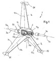
- a device 1 of FIG. maintaining and guiding according to the invention usable to support and correctly position a underwater object towed, especially an antenna drawn linear acoustic, 3, schematized here under the shape of a long cable.
- the device 1 comprises a hollow central body 5, and several stabilizing wings, individually steerable 7a, 7b, 7c, here the number of 3.
- the body 5 has a longitudinal axis 5a.
- This body comprises a fixed central part 9 and a 11 concentric outer shell, rotating rise with the wings, around the central part and the axis 5a, so that in the event of an obstacle the wings escape laterally, pivoting around the axis 5a.
- the wings which extend along an axis transverse (radial) to the axis 5a, are also mounted swiveling (about 5 to 30 ° and preferably up to about 20 °) around their transverse axis respective, 13a, 13b, 13c.
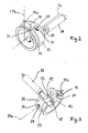
- each wing is fixed towards its root, such as 17b for the wing 7b, to a radial shaft (shaft 15b extending along the axis 13b for the wing 7b).
- the radial shaft 15b passes through the hull 11 under which he is fixedly connected to a transverse leg 19 provided with a nipple or lug 21 which slides in the groove, or groove 23 of a ring 25 ( Figures 2 and 3).
- the groove 23 extends over the entire periphery outer ring and in a radial plane to the axis 5a, concentrically.
- the ring 25 is crossed by a oblong hole (or preferably two holes diametrically opposite) 29 in which (each of which) moves a finger 31 ( Figures 2 and 3).
- the oblong hole 29 has its axis of elongation parallel to the circular groove 23.
- the finger 31 is an element of a radial cam device (or eccentric) 33 driven by a controlled angle drive 35 by the output shaft 37 (parallel to the axis 5a) of a electric motor 39.
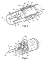
- the shaft 37 is more precisely controlled by a motorcycle gearbox which rotates an axial screw 41 on which meshes the radial gear wheel 43, thus defining the angle gear 35 (FIGS. 5).
- This device is moved by a tree 45 (extending in a plane radial to the axis 5a) rotating around its 33a axis and guided by the wheel 43 which rolls in a light 47 parallel to the axis 5a, under the control of the output shaft 37 ( Figure 3).
- the rings 25, 49, 51 are offset along the axis 5a, of same as the three wings (see Figures 1, 4 and 5 together).
- each wing can thus be adapted according to the situation.
- the wing upper 7a is rotated about its axis 13a, even for the two lower wings 7b, 7c (meaning reverse each other) to cancel the moment along axis 5a in order to preserve the whole of system in vertical position.
- the force resultant applied is directed laterally by relative to axis 5a, to the left or the right.
- the fixed central part 9 of body 5 is provided at its longitudinal ends opposite, respectively of a first and a second connection tips 53, 55 designed to engage complementary ends provided on the ends of said upstream and downstream sections 10, 20 of the towed object.
- the hull 11 and the wings 7a, 7b, 7c are separable of the inner part 9 of the body.
- the wings and the inner part 9 may include an interlocking system can be dismantled, for example a system with bayonet, or a screwed connection).
- outer shell 11 As for the outer shell 11, it is advantageously carried out in two half-shells 11a, 11b joined together according to a plan containing axis 5a and again connected by an interlocking system removable, in itself known.
- the device 1 ensures so among other things a depth control by generating a vertical force on the towed object (at least the sections adjacent to it) to establish at least these sections to a predefined depth.
- the depth control is preferably a local control using a pressure signal.
- This signal can be provided by a local sensor of pressure 61 disposed within the device 1 (body 9, and more particularly zone 9a reserved for the electronics in Figure 4).
- Another possibility is to use a signal pressure provided by the outside for example by a cable connected to the device electronics 1. It can be then use a remote sensor and communicating with the electronic processing unit (or microcontroller 60 shown in Figure 6) and connected well heard by means of control of the inclination of the wings already detailed.
- Each wing is also advantageously connected to a position sensor 62 housed at 9a and measuring the angle of inclination (absolute angle) of each wing around its radial axis.
- This position information is loaded into embedded electronics (microcontroller 60) for a control by a control loop.
- electronics embedded memory loads data related to the towed line of objects which is substantially parallel (if such a line exists), so that the concerned device is adapted to apply, (via the wings moved by their actuators 63; Figures 5 and 6) a lateral force to the adjacent sections on which it can act, to adapt the relative distance with the line (s) close (s).
- Distance data can in particular be provided by a sensor, in particular a sensor 64, providing these data to the microcontroller 60, by any means of communication appropriate (cable in particular).
- the sensor 64 can be housed at 9a, or located at a distance from the device 1.
- the actuators 63 of FIG. 6 relate in particular to electric motors (such as 39) and to angle and cam gear devices (or eccentric) 33 presented before (see Figure 5).
- the device 1 comprises three wings
- a 69 power management system (plus detailed in Figure 7) also allows to exonerate of the problem of the relatively weak power electric available.
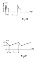
- each engine (such as 39), here concerned operates at an initial voltage of 12 volts (provided by a battery of (super) capacitors spotted 65 integrated to the interface 67 that receives the sensor data 64 to transmit them after processing towards the microcontroller 60, FIG. choose, for example, to use it between, about 11 and 12 volts ( Figures 7 and 9).
- the source current 78 (with for example a battery of accumulators, transistor 75 and resistor 79) establishes the maximum current available for the motor 39, when the charge of the capacitor 73 is reached ( Figures 7 and 9).
- the total power delivered may be the order of 4 to 5 watts, with operation between about 10 and 12 volts and a medium power continues weaker.
- the discharge in the engines may be triggered / interrupted by comparing the voltage of capacitors with a theoretical maximum preprogrammed and minimum voltages also predefined.
- a direct measure can be using a rotary sensor, in particular a sensor without Hall effect contact.
- the sensor 62 provided for each wing will have to be calibrated to operate operationally.
- both lower wings 7b, 7c are each provided with their free end, of a heavy mass (lead), respectively 80, 82 in Figure 1, the wing 7a being optionally provided, also at its free end, a bead 84 enclosing a lightweight foam block or equivalent, low density, preferably of lower density than that of water, so floating.
Landscapes
- Engineering & Computer Science (AREA)
- Life Sciences & Earth Sciences (AREA)
- Mechanical Engineering (AREA)
- Physics & Mathematics (AREA)
- Chemical & Material Sciences (AREA)
- Geology (AREA)
- Remote Sensing (AREA)
- General Life Sciences & Earth Sciences (AREA)
- General Physics & Mathematics (AREA)
- Geophysics (AREA)
- Environmental & Geological Engineering (AREA)
- Aviation & Aerospace Engineering (AREA)
- Acoustics & Sound (AREA)
- Combustion & Propulsion (AREA)
- Ocean & Marine Engineering (AREA)
- Oceanography (AREA)
- Control Of Position, Course, Altitude, Or Attitude Of Moving Bodies (AREA)
- Toys (AREA)
- Other Liquid Machine Or Engine Such As Wave Power Use (AREA)
- Transmission Devices (AREA)
- Catching Or Destruction (AREA)
- Vehicle Cleaning, Maintenance, Repair, Refitting, And Outriggers (AREA)
- Geophysics And Detection Of Objects (AREA)
- Aiming, Guidance, Guns With A Light Source, Armor, Camouflage, And Targets (AREA)
- Details Of Aerials (AREA)
- Underground Or Underwater Handling Of Building Materials (AREA)
- Position Fixing By Use Of Radio Waves (AREA)
Abstract
Description
L'invention concerne un dispositif pour contrôler la navigation d'un objet sous-marin remorqué, tel en particulier qu'une antenne acoustique linéaire remorquée.The invention relates to a device for controlling the navigation of a towed underwater object, such as particular that a linear acoustic antenna towed.
Notamment pour assurer l'acquisition de données sismiques (en particulier en trois dimensions), il est connu de remorquer un objet sous-marin (tel que l'antenne précitée), en mer.In particular to ensure the acquisition of data (in particular three-dimensional), it is known to tow an underwater object (such as the aforementioned antenna), at sea.
Typiquement, cette antenne se présente en quelque sorte comme un long câble. Typiquement, plusieurs câbles sont disposés côte à côte, souvent une dizaine, remorqués ensemble.Typically, this antenna presents itself sort of like a long cable. Typically, several cables are arranged side by side, often ten, towed together.
Or, il importe de positionner correctement ces engins les uns par rapport aux autres (notamment pour éviter qu'ils se croisent). Il est également utile de définir et de contrôler leur profondeur d'immersion.However, it is important to correctly position these gear with respect to each other (especially for avoid that they cross each other). It is also useful to define and control their depth of immersion.
On a déjà proposé de tels dispositifs de contrôle de la navigation d'objets sous-marins remorqués.Such control devices have already been proposed. the navigation of underwater objects towed.
Toutefois, des problèmes demeurent liés, en tout ou partie, à la fiabilité et à l'efficacité de ces dispositifs, à leur coût et à leur facilité d'utilisation et/ou d'entretien. However, problems remain related, in all or part, to the reliability and efficiency of these devices, at their cost and ease use and / or maintenance.
Pour apporter une solution à tout ou partie des problèmes ci-dessus, il est tout d'abord proposé que le dispositif de l'invention comprenne :
- un corps présentant un axe longitudinal, le corps étant muni de moyens de fixation pour le fixer de manière démontable audit objet sous-marin remorqué, et
- plusieurs ailes stabilisatrices, chacune liée au corps et s'étendant suivant un axe transversal à l'axe longitudinal de ce corps, chaque aile étant orientable par rapport au corps par pivotement autour de son axe transversal, par l'intermédiaire de moyens de contrôle, pour modifier l'angle d'inclinaison desdites ailes.
- a body having a longitudinal axis, the body being provided with fixing means for detachably fixing said towed underwater object, and
- a plurality of stabilizing wings, each connected to the body and extending along an axis transverse to the longitudinal axis of this body, each wing being orientable relative to the body by pivoting about its transverse axis, by means of control means, to change the angle of inclination of said wings.
Un problème souvent rencontré lorsque le dispositif et l'objet sous-marin remorqué sont opérationnels, entraínés derrière un navire tracteur, concerne la rencontre inopinée avec des obstacles. L'objet et/ou le dispositif peuvent alors être gênés dans leur progression, dans leur efficacité, voire être endommagés.A problem often encountered when the device and the towed underwater object are operational, driven behind a tractor ship, concerns the Unexpected encounter with obstacles. The object and / or the device can then be embarrassed in their progress, in their effectiveness, or even damaged.
Pour apporter une solution à ces problèmes, il est proposé :
- que le corps comprenne:
- une partie intérieure fixe pourvue desdits moyens de fixation avec l'objet sous-marin remorqué,
- et une coque extérieure mobile en rotation vis-à-vis de la pièce intérieure fixe, autour dudit axe longitudinal,
- et que chaque aile soit liée à une extrémité à un arbre s'étendant sensiblement radialement par rapport audit axe longitudinal et qui traverse la coque extérieure mobile pour coopérer avec un ergot engagé dans une gorge circulaire ménagée dans une bague s'étendant autour de ladite partie intérieure fixe, coaxialement, l'ergot glissant dans la gorge lorsque chaque aile et la coque extérieure mobile tournent autour dudit axe longitudinal du corps.
- that the body understands:
- a fixed inner part provided with said fastening means with the underwater object towed,
- and an outer shell movable in rotation with respect to the fixed inner part, about said longitudinal axis,
- and that each wing is linked at one end to a shaft extending substantially radially relative to said longitudinal axis and which passes through the movable outer shell to cooperate with a lug engaged in a circular groove formed in a ring extending around said portion internally fixed, coaxially, the lug sliding in the groove when each wing and the outer mobile shell rotate around said longitudinal axis of the body.
Ainsi, les ailes et la coque extérieure vont pouvoir « s'échapper » par pivotement autour de l'axe longitudinal du corps, en cas de rencontre inopinée avec des obstacles.Thus, the wings and the outer shell go ability to "escape" by pivoting around the axis longitudinal body, in case of unexpected encounter with obstacles.
En relation avec tout ou partie de ce qui précède, on conseille par ailleurs que le dispositif de l'invention comprenne trois ailes disposées autour de l'axe longitudinal, avec deux ailes inférieures définissant entre elles un « V » et une aile supérieure sensiblement verticale, lesdits moyens de contrôle agissant sur ces ailes pour adapter la profondeur d'immersion et la position latérale du dispositif par rapport à un axe de référence le long duquel s'étend globalement l'objet sous-marin remorqué.In relation to all or part of the foregoing, it is further advised that the the invention comprises three wings arranged around the longitudinal axis, with two lower wings defining between them a "V" and an upper wing substantially vertical, said control means acting on these wings to adjust the depth immersion and the lateral position of the device by relative to a reference axis along which extends globally the underwater object towed.
Selon un aspect important de l'invention, il a été ici tenu compte du problème lié à la manière d'entraíner efficacement, de façon fiable, les (chaque) aile(s) autour de l'axe transversal correspondant.According to an important aspect of the invention, it has been here taken into account the problem related to the way to drive efficiently, reliably, the (each) wing (s) around the corresponding transverse axis.
En relation avec cet aspect, il est proposé dans l'invention :
- que l'entraínement en rotation de chaque aile autour de son axe transversal soit assuré par l'intermédiaire d'un excentrique lié, à une première extrémité, à l'arbre transversal de cette aile et, à une seconde extrémité, à l'ergot engagé dans la gorge circulaire de la bague correspondante, laquelle est montée coulissante autour de ladite partie intérieure fixe, coaxialement à elle, de sorte que la rotation de l'aile considérée autour de son axe transversal s'opère par déplacement de ladite bague suivant l'axe longitudinal du corps ;
- et/ou que l'entraínement en rotation de chaque aile autour de son axe transversal soit assuré par l'intermédiaire d'une came ayant un axe de rotation décalé par rapport à celui de l'aile correspondante et se déplaçant dans une lumière s'étendant sur un secteur angulaire d'un plan sensiblement radial audit axe longitudinal, la came étant mue par un arbre tournant autour d'un axe transversal à cet axe longitudinal, l'arbre étant entraíné par une roue mue en rotation par un dispositif rotatif à renvoi d'angle entraíné lui-même par un moyen d'entraínement rotatif tournant autour d'un axe sensiblement parallèle à l'axe longitudinal du corps ;
- et, en relation avec la caractéristique qui précède, que l'arbre tournant présente si nécessaire, à son extrémité libre, un excentrique qui se déplace dans ladite lumière, définissant ainsi la came qui assure l'orientation angulaire de chaque aile. la lumière étant ménagée dans ladite bague qui s'étend autour de la partie intérieure fixe du corps, de sorte que la rotation de l'aile considérée autour de son axe transversal s'opère par déplacement de ladite bague suivant l'axe longitudinal du corps.
- that the drive in rotation of each wing about its transverse axis is ensured by means of an eccentric linked at a first end to the transverse shaft of this wing and, at a second end, to the pin engaged in the circular groove of the corresponding ring, which is slidably mounted around said fixed inner part, coaxially with it, so that the rotation of the wing considered around its transverse axis is effected by displacement of said ring according to the longitudinal axis of the body;
- and / or that the drive in rotation of each wing about its transverse axis is provided by means of a cam having an axis of rotation offset from that of the corresponding wing and moving in a light s' extending over an angular sector of a substantially radial plane to said longitudinal axis, the cam being driven by a shaft rotating about an axis transverse to this longitudinal axis, the shaft being driven by a wheel rotated by a rotary device to Angle gear driven itself by a rotational drive means rotating about an axis substantially parallel to the longitudinal axis of the body;
- and, in connection with the preceding feature, that the rotating shaft has, if necessary, at its free end, an eccentric which moves in said light, thereby defining the cam which provides the angular orientation of each wing. the light being formed in said ring which extends around the fixed inner part of the body, so that the rotation of the wing considered around its transverse axis is effected by displacement of said ring along the longitudinal axis of the body .
La deuxième caractéristique ci-dessus permet en particulier de conserver les angles d'attaque des ailes constants, tout en autorisant une rotation du dispositif autour de l'axe dit « longitudinal » du corps.The second feature above allows in particular to maintain wing angles of attack while allowing a rotation of the device around the so-called "longitudinal" axis of the body.
En particulier avec un système « tripode » comprenant donc trois ailes comme déjà indiqué, on conseille que le dispositif comprenne au moins autant de gorges circulaires que de dites ailes, ces gorges circulaires étant disposées successivement les unes à la suite des autres suivant ledit axe longitudinal, de sorte que les ailes sont décalées les unes par rapport aux autres suivant cet axe longitudinal.Especially with a tripod system therefore comprising three wings as already indicated, one advises that the device include at least as much of circular gorges that said wings, these throats circular ones being successively arranged following the others along the said longitudinal axis, so that the wings are shifted relative to each other to others along this longitudinal axis.
Ceci assure un mécanisme relativement simple et fiable, sans gêne pour l'équilibre et la stabilité.This ensures a relatively simple mechanism and reliable, without hindrance for balance and stability.
Un autre problème rencontré concerne la possibilité d'enrouler ensemble sur de gros tourets, le dispositif de l'invention et l'objet sous-marin remorqué (en particulier s'il s'agit d'une sorte de câble comme déjà indiqué), sans avoir à retirer les dispositifs de contrôle de l'invention périodiquement placés le long du câble/objet et sans risquer d'endommager ces dispositifs.Another problem encountered concerns the possibility to wind together on large drums, the device of the invention and the underwater object towed (in especially if it is a kind of cable as already indicated), without having to remove the control of the invention periodically placed along of cable / object and without risk of damaging these devices.
Une solution proposée dans l'invention consiste en ce que :
- la coque extérieure mobile du corps comprend deux demi-coquilles séparables l'une vis à vis de l'autre et vis à vis de la partie intérieure fixe,
- et l'arbre de rotation de chaque aile est lié de façon amovible au corps intérieur,
- the movable outer shell of the body comprises two separable half-shells one opposite the other and opposite the fixed inner part,
- and the rotation shaft of each wing is removably connected to the inner body,
Un autre problème rencontré concerne la manière de commander la rotation des ailes, à partir de l'intérieur du corps.Another problem encountered is the way of order the wings rotation, starting from inside the body.
Pour cela, on conseille :
- que la rotation des (de chaque) aile(s) autour de son axe transversal soit commandée au moins par un moteur électrique fonctionnant par intermittence pour dévier l'(les) aile(s) concernée(s), le (chaque) moteur étant pour cela relié, de préférence pour chaque aile, à au moins un condensateur présentant des temps de charge et de décharge, le moteur étant mis en fonctionnement pendant le temps de décharge du (des) condensateur(s) et étant arrêté pendant son(leur) temps de charge, ou, selon une autre formulation, que la fréquence d'utilisation des moteurs résulte en une puissance moyenne constante et faible,
- et éventuellement que, dans l'un ou l'autre des cas ci-dessus, le condensateur appartienne avantageusement à un circuit électrique comprenant une source de courant, le condensateur étant chargé, pendant son temps de charge, par un courant constant.
- that the rotation of (each) wing (s) around its transverse axis is controlled at least by an intermittently powered electric motor to deflect the wing (s) concerned (s), the (each) engine being for this purpose, preferably for each wing, at least one capacitor having charging and discharging times, the motor being operated during the discharge time of the capacitor (s) and being stopped during its (their) ) charging time, or, alternatively, that the frequency of use of the motors results in a constant and low average power,
- and possibly that, in one or the other of the above cases, the capacitor advantageously belongs to an electric circuit comprising a current source, the capacitor being charged, during its charging time, with a constant current.
Ainsi, on obtiendra une alimentation des motorisations pour la rotation des ailes par charges et décharges de condensateurs. Thus, we will get a diet of drives for wing rotation by loads and capacitor discharges.
D'autres caractéristiques et avantages de l'invention apparaítront encore dans la description qui suit, relative à un mode particulier, préféré, de réalisation.Other features and benefits of invention will still appear in the description which follows, relating to a particular, preferred mode of production.
Dans cette description :
Sur la figure 1, on voit un dispositif 1 de
maintien et de guidage conforme à l'invention,
utilisable pour soutenir et positionner correctement un
objet sous-marin remorqué, en particulier une antenne
acoustique linéaire remorquée, 3, schématisée ici sous
la forme d'un long câble. In FIG. 1, a
Le dispositif 1 comprend un corps central creux 5,
et plusieurs ailes stabilisatrices, individuellement
orientables 7a, 7b, 7c, ici au nombre de 3.The
Le corps 5 présente un axe longitudinal 5a.The
Ce corps comprend une partie centrale fixe 9 et une
coque extérieure 11 concentrique, montée tournante avec
les ailes, autour de la partie centrale et de l'axe 5a,
de manière qu'en cas d'obstacle, les ailes puissent
s'échapper latéralement, en pivotant autour de l'axe
5a.This body comprises a fixed
Les ailes, qui s'étendent suivant un axe
transversal (radial) à l'axe 5a, sont en outre montées
pivotantes (sur environ 5 à 30° et de préférence
jusqu'à 20° environ) autour de leur axe transversal
respectif, 13a, 13b, 13c.The wings, which extend along an axis
transverse (radial) to the
Pour obtenir ces mouvements, de préférence chaque
aile est fixée vers son emplanture, telle que 17b pour
l'aile 7b, à un arbre radial (arbre 15b s'étendant
suivant l'axe 13b pour l'aile 7b).To obtain these movements, preferably each
wing is fixed towards its root, such as 17b for
the
Pour l'explication concernant les ailes,
considérons l'aile 7b, le montage des autres ailes
étant identique : l'arbre radial 15b traverse la coque
extérieure 11 sous laquelle il est relié fixement à une
patte transversale 19 pourvue d'un téton ou ergot 21
qui coulisse dans la rainure, ou gorge 23 d'une bague
25 (figures 2 et 3). For the explanation concerning the wings,
consider the
La gorge 23 s'étend sur toute la périphérie
extérieure de la bague et dans un plan radial à l'axe
5a, concentriquement.The
En décalage (suivant cet axe longitudinal 5a) par
rapport à la rainure, la bague 25 est traversée par un
trou oblong (ou de préférence deux trous diamétralement
opposés) 29 dans lequel (chacun desquels) se déplace un
doigt 31 (figures 2 et 3).Offset (along this
Le trou oblong 29 présente son axe d'allongement
parallèlement à la gorge circulaire 23.The
Il est donc dans un plan radial à l'axe 5a.It is therefore in a plane radial to the
Comme montré également figures 4 ou 5, le doigt 31
est un élément d'un dispositif radial à came (ou
excentrique) 33 mû par un renvoi d'angle 35 commandé
par l'arbre de sortie 37 (parallèle à l'axe 5a) d'un
moteur électrique 39.As also shown in FIGS. 4 or 5, the
Dans le mode de réalisation préféré illustré,
l'arbre 37 est plus précisément commandé par un moto
réducteur qui entraíne en rotation une vis axiale 41
sur laquelle engrène la roue dentée radiale 43,
définissant ainsi le renvoi d'angle 35 (figures 3 et
5).In the preferred embodiment illustrated,
the
Radialement, au-delà de la zone dentée 43, la roue
se prolonge de part et d'autre par une tige à
excentrique qui, avec son doigt 31, définit le
dispositif radial à came 33 (figure 5). Radially, beyond the
Ce dispositif est mû par un arbre 45 (s'étendant
dans un plan radial à l'axe 5a) tournant autour de son
axe 33a et guidé par la roue 43 qui roule dans une
lumière 47 parallèle à l'axe 5a, sous la commande de
l'arbre de sortie 37 (figure 3).This device is moved by a tree 45 (extending
in a plane radial to the
Avec un tel système de commande des ailes, les
bagues 25, 49, 51 sont décalées suivant l'axe 5a, de
même que les trois ailes (voir figures 1, 4 et 5
réunies).With such a wing control system, the
L'orientation angulaire par rapport à l'axe 5a de
chaque aile peut ainsi être adaptée en fonction de la
situation.The angular orientation with respect to the
Telle est la disposition des ailes avec, en mode
opérationnel, dans l'eau et en situation normale,
stable, une aile supérieure verticale 7a et deux ailes
inférieures inclinées 7b, 7c ayant de préférence le
même écart angulaire a par rapport à la verticale
passant par l'aile 7a. Ceci permet d'assurer un
contrôle de la profondeur et de la position relative
entre deux lignes d'objets remorqués normalement
sensiblement parallèles.This is the arrangement of the wings with, in
operational, in the water and in a normal situation,
stable, a vertical
Pour un contrôle de la profondeur, seules les deux
ailes inférieures 7b, 7c sont inclinées autour de leur
axe de rotation 13b, 13c, de sorte que le dispositif 1
applique une force résultante verticale sur les
tronçons amont et aval 3a, 3b de l'objet remorqué
auquel il est relié (on suppose bien entendu que
l'ensemble avance). For depth control, only the two
Pour un contrôle latéral (plan horizontal), l'aile
supérieure 7a est tournée autour de son axe 13a, de
même pour les deux ailes inférieures 7b, 7c (en sens
inverse l'une de l'autre) afin d'annuler le moment
selon l'axe 5a dans le but de conserver l'ensemble du
système en position verticale.For a lateral control (horizontal plane), the wing
upper 7a is rotated about its
Si l'ensemble objet tracté et dispositif 1 avance,
entraíné typiquement par un navire de surface, la force
résultante appliquée est dirigée latéralement par
rapport à l'axe 5a, vers la gauche ou la droite.If the entire towed object and
Pour une liaison avec les tronçons d'objets tractés
amont et aval 3a, 3b (liaison mécanique, électrique,
circulation de signaux ...), la partie centrale fixe 9 du
corps 5 est munie, à ses extrémités longitudinales
opposées, respectivement d'un premier et d'un second
embouts 53, 55 de raccordement conçus pour engager des
embouts complémentaires prévus sur les extrémités
correspondantes desdits tronçons amont et aval 10, 20
de l'objet tracté.For a connection with the sections of towed objects
upstream and downstream 3a, 3b (mechanical, electrical,
signal flow ...), the fixed
En outre, en particulier pour autoriser un
enroulement de la ligne tracté sur de gros rouleaux, en
entraínant au passage les dispositifs 1 périodiquement
disposés le long des tronçons concernés, la coque
extérieure 11 et les ailes 7a, 7b, 7c sont séparables
de la partie intérieure 9 du corps.In addition, in particular to allow
winding of the towed line on large rollers,
driving through the
Pour cela, les ailes et la partie intérieure 9
peuvent comprendre un système d'interverrouillage
démontable, en soit connu (par exemple un système à
baïonnette, ou encore une liaison vissée). For this, the wings and the
Quant à la coque extérieure 11, elle est
avantageusement réalisée en deux demi-coquilles 11a,
11b réunies ensemble suivant un plan contenant l'axe 5a
et là encore relié par un système d'interverrouillage
démontable, en soi connu.As for the
Comme indiqué ci-dessus, le dispositif 1 assure
donc entre autre un contrôle de profondeur en générant
une force verticale sur l'objet tracté (au moins les
tronçons qui lui sont adjacents) pour établir au moins
ces tronçons à une profondeur prédéfinie.As indicated above, the
Le contrôle de la profondeur est de préférence un contrôle local utilisant un signal de pression.The depth control is preferably a local control using a pressure signal.
Ce signal peut être fourni par un capteur local de
pression 61 disposé à l'intérieur du dispositif 1
(corps 9 ; et plus particulièrement zone 9a réservée à
l'électronique sur la figure 4).This signal can be provided by a local sensor of
Une autre possibilité consiste à utiliser un signal
de pression fourni par l'extérieur par exemple par un
câble relié à l'électronique du dispositif 1. On peut
alors utiliser un capteur disposé à distance et
communiquant avec l'unité électronique de traitement
(ou microcontrôleur 60 montré figure 6) et relié bien
entendu au moyen de commande de l'inclinaison des ailes
déjà détaillé.Another possibility is to use a signal
pressure provided by the outside for example by a
cable connected to the
Chaque aile est en outre avantageusement reliée à
un capteur de position 62 logé en 9a et mesurant
l'angle d'inclinaison (angle absolu) de chaque aile
autour de son axe radial.Each wing is also advantageously connected to
a
Cette information de position est chargée dans l'électronique embarquée (microcontrôleur 60) pour un contrôle par une boucle de contrôle.This position information is loaded into embedded electronics (microcontroller 60) for a control by a control loop.
Pour contrôler la position latérale du dispositif 1
et de ses tronçons adjacents 3a, 3b, l'électronique
embarquée charge en mémoire des données relatives à la
ligne d'objets tractée qui lui est sensiblement
parallèle (si une telle ligne existe), de sorte que le
dispositif concerné est adapté pour appliquer, (via les
ailes mues par leurs actionneurs 63 ; figures 5 et 6)
une force latérale aux tronçons adjacents sur lesquels
elle peut agir, pour adapter la distance relative avec
la (les) ligne(s) proche(s).To control the lateral position of the
Les données de distance peuvent en particulier être
fournies par un capteur, en particulier un capteur
acoustique 64, fournissant ces données au
microcontrôleur 60, par tout moyen de communication
approprié (câble en particulier). Le capteur 64 peut
être logé en 9a, ou situé à distance du dispositif 1.Distance data can in particular be
provided by a sensor, in particular a
Les actionneurs 63 de la figure 6 se rapportent en
particulier aux moteurs électriques (tels que 39) et
aux dispositifs à renvoi d'angle 35 et à came (ou
excentrique) 33 présentés avant (cf figure 5).The
De préférence, si le dispositif 1 comprend trois
ailes, on trouvera dans le corps 5, trois moteurs (voir
figure 4) et trois dispositifs 33, 35 de commande
associés à trois bagues circulaires (25, 49, 51 sur la
figure 4) coulissantes parallèlement à l'axe 5a et
disposées donc l'une derrière l'autre, chacune avec une
gorge extérieure périphérique (respectivement 23, 23',
23'') dans laquelle se déplace et tourne si nécessaire
le doigt de l'excentrique correspondant, chaque bague
étant traversée, derrière, par la lumière (29, 29' ou
29") où s'engage le doigt (31, 31', 31") de la came
33 concernée.Preferably, if the
Revenant figure 6, on constate que le contrôle de
la profondeur est donc assuré avantageusement par un
capteur 61 de pression sensible à la pression dans
l'environnement du dispositif.Returning to Figure 6, we find that the control of
the depth is therefore advantageously ensured by a
Un système de gestion de la puissance 69 (plus détaillé sur la figure 7) permet en outre de s'exonérer du problème de la relativement faible puissance électrique disponible.A 69 power management system (plus detailed in Figure 7) also allows to exonerate of the problem of the relatively weak power electric available.
Ainsi, dès lors que les moteurs 39, 39', 39''
consomment en fonctionnement une puissance relativement
importante, on va les faire fonctionner par
intermittence, pour atteindre par cycles successifs de
fonctionnement et d'arrêt, l'angle d'inclinaison voulu
pour les ailes 7a, 7b, 7c.Thus, since the
En agissant ainsi, on assure une consommation électrique moyenne acceptable.By doing so, we ensure a consumption average electrical acceptable.
Pour lisser les pics de consommation, on utilise les cycles de charges/décharges de (super) condensateurs, de préférence plusieurs en série. To smooth peaks of consumption, we use charge / discharge cycles of (super) capacitors, preferably several in series.
Le schéma de principe de la figure 7 et les figures
8 et 9 montrent que le cycle total du (de chaque)
condensateur 70 est Tc + Td (correspondant de
préférence à la période des cycles d'acquisition en
entrée du capteur acoustique 64).The block diagram of Figure 7 and the figures
8 and 9 show that the total cycle of (each)
Si le (chaque) moteur (tel que 39), ici concerné
fonctionne sous une tension initiale de 12 volts
(fournie par une batterie de (super) condensateurs
repérée 65 intégrée à l'interface 67 qui reçoit les
données du capteur 64 pour les transmettre après
traitement vers le microcontrôleur 60, figure 6), on
choisira par exemple de l'utiliser entre, environ 11 et
12 volts (figures 7 et 9).If the (each) engine (such as 39), here concerned
operates at an initial voltage of 12 volts
(provided by a battery of (super) capacitors
spotted 65 integrated to the
On voit figure 8 comment évolue en conséquence
l'intensité du courant disponible pour le moteur. Un
courant d'intensité constant (provenant de la batterie)
charge continûment la capacité 73 branchée entre le
transistor 75 et la masse 77 (figure 7).We see figure 8 how evolves accordingly
the current available to the motor. A
constant current (from the battery)
continually charges the
Sous la commande du microcontrôleur 60, la source
de courant 78 (avec par exemple une batterie
d'accumulateurs, le transistor 75 et la résistance 79)
établit l'intensité maximum de courant disponible pour
le moteur 39, lorsque la charge du condensateur 73 est
atteinte (figures 7 et 9).Under the control of the
Avec par exemple six condensateurs, de 5F chacun, en série, montés selon le principe de fonctionnement précité et trois motoréducteurs à courant continu (DC), on doit pouvoir faire fonctionner ces moteurs pendant environ 2 à 4 secondes (Td) pour des temps intermédiaire d'arrêt (Tc) de l'ordre de 30 à 40 secondes, la puissance totale délivrée pouvant être de l'ordre de 4 à 5 watts, avec un fonctionnement entre environ 10 et 12 volts et une puissance moyenne continue plus faible.With for example six capacitors, of 5F each, in series, mounted according to the principle of operation mentioned above and three DC gearmotors, we must be able to operate these engines during about 2 to 4 seconds (Td) for times intermediate stop (Tc) of the order of 30 to 40 seconds, the total power delivered may be the order of 4 to 5 watts, with operation between about 10 and 12 volts and a medium power continues weaker.
La décharge dans les moteurs pourra être déclenchée/interrompue en comparant la tension des condensateurs avec un maximum théorique préprogrammé et des tensions minimum également prédéfinies.The discharge in the engines may be triggered / interrupted by comparing the voltage of capacitors with a theoretical maximum preprogrammed and minimum voltages also predefined.
Une telle solution permettra en outre, en cas d'urgence, de décharger dans les moteurs pendant un temps supérieur à celui prévu, ceci nécessitant toutefois bien entendu un temps de recharge plus long.Such a solution will also, in case emergency, to unload in the engines during a longer than expected, this requiring however of course a longer cooldown.
Concernant maintenant la position angulaire des
ailes, celle-ci sera avantageusement mesurée sur l'axe
de rotation 33a des dispositifs à excentrique 33.Regarding now the angular position of
wings, it will be advantageously measured on the axis
of
On peut prévoir pour cela une mesure directe, en utilisant un capteur rotatif en particulier un capteur sans contact à effet Hall.For this purpose, a direct measure can be using a rotary sensor, in particular a sensor without Hall effect contact.
S'il s'agit d'un capteur d'angle absolu (solution
préférée), le capteur 62 prévu pour chaque aile devra
être calibré pour fonctionner de façon opérationnelle.If it is an absolute angle sensor (solution
preferred), the
Pour l'équilibrage du dispositif 1 en
fonctionnement, on conseille par ailleurs que les deux
ailes inférieures 7b, 7c soient pourvues chacune, à
leur extrémité libre, d'une masse pesante (plomb),
respectivement 80, 82 sur la figure 1, l'aile
supérieure 7a étant éventuellement pourvue, également à
son extrémité libre, d'un bourrelet 84 renfermant un
bloc de mousse légère ou équivalent, de faible densité,
de préférence de densité inférieure à celle de l'eau,
donc flottante.For the balancing of the
Claims (18)
Applications Claiming Priority (2)
| Application Number | Priority Date | Filing Date | Title |
|---|---|---|---|
| FR0405430 | 2004-05-18 | ||
| FR0405430A FR2870509B1 (en) | 2004-05-18 | 2004-05-18 | DEVICE FOR MONITORING THE NAVIGATION OF A SUB-MARINE OBJECT TRAILER |
Publications (3)
| Publication Number | Publication Date |
|---|---|
| EP1598265A2 true EP1598265A2 (en) | 2005-11-23 |
| EP1598265A3 EP1598265A3 (en) | 2014-01-01 |
| EP1598265B1 EP1598265B1 (en) | 2015-05-06 |
Family
ID=34942265
Family Applications (1)
| Application Number | Title | Priority Date | Filing Date |
|---|---|---|---|
| EP20050291003 Expired - Lifetime EP1598265B1 (en) | 2004-05-18 | 2005-05-10 | Arrangement for steering a towed submerged object |
Country Status (5)
| Country | Link |
|---|---|
| US (1) | US7267070B2 (en) |
| EP (1) | EP1598265B1 (en) |
| CN (1) | CN100534857C (en) |
| FR (1) | FR2870509B1 (en) |
| NO (1) | NO337743B1 (en) |
Cited By (2)
| Publication number | Priority date | Publication date | Assignee | Title |
|---|---|---|---|---|
| FR2903655A1 (en) * | 2006-07-13 | 2008-01-18 | Cybernetix Sa | DEVICE FOR DYNAMIC STABILIZATION OF SUBMARINE ENGINE |
| CN105129055A (en) * | 2015-09-09 | 2015-12-09 | 北京南风科创应用技术有限公司 | ROV (remote operated vehicle) and underwater scanning method |
Families Citing this family (19)
| Publication number | Priority date | Publication date | Assignee | Title |
|---|---|---|---|---|
| US7933163B2 (en) * | 2006-07-07 | 2011-04-26 | Kongsberg Seatex As | Method and system for controlling the position of marine seismic streamers |
| FR2917063B1 (en) * | 2007-06-07 | 2009-12-04 | Cybernetix | DEVICE FOR CLOSING A FUSELAGE RELATING TO A SUBMARINE OBJECT TRAILER AND EQUIP EQUIPPED THEREWITH |
| US8976622B2 (en) * | 2008-04-21 | 2015-03-10 | Pgs Geophysical As | Methods for controlling towed marine sensor array geometry |
| FR2940838B1 (en) | 2009-01-05 | 2012-12-28 | Michel Manin | IMPROVED METHOD AND APPARATUS FOR SEISMIC MARINE PROSPECTING |
| FR2947390B1 (en) * | 2009-06-30 | 2011-07-01 | Sercel Rech Const Elect | METHOD FOR ASSISTING THE POSITIONING OF LINEAR ACOUSTIC LINEAR ANTENNAS, COMPRISING A DEFINITION STEP AND A GENERATION STEP FOR SEPARATE ACOUSTIC CYVALS |
| NO332115B1 (en) * | 2009-07-07 | 2012-06-25 | Kongsberg Seatex As | Control device for positioning instrumented rope cable in water |
| FR2961317B1 (en) | 2010-06-10 | 2014-01-17 | Kietta | SEISMIC PROSPECTING METHOD IN AQUATIC ENVIRONMENT |
| US8792297B2 (en) | 2010-07-02 | 2014-07-29 | Pgs Geophysical As | Methods for gathering marine geophysical data |
| US9130264B2 (en) | 2012-05-09 | 2015-09-08 | Jeffrey Gervais | Apparatus for raising and lowering antennae |
| US9423527B2 (en) | 2013-03-08 | 2016-08-23 | Cgg Services Sa | Autonomous cleaning device for seismic streamers and method |
| WO2014135706A2 (en) * | 2013-03-08 | 2014-09-12 | Cgg Services Sa | Autonomous cleaning device for seismic streamers and method |
| EP2857869B1 (en) * | 2013-10-07 | 2023-05-03 | Sercel | Operation managing system for driving a navigation control device according to a degraded operating mode |
| FR3043791B1 (en) | 2015-11-17 | 2018-11-16 | Kietta | CONTROLLING THE DEPTH OF A SEISMIC CABLE |
| FR3054890B1 (en) | 2016-08-02 | 2019-07-05 | Kietta | CHECKING THE HORIZONTAL POSITION OF A SEISMIC CABLE |
| JP6979828B2 (en) * | 2017-08-22 | 2021-12-15 | 株式会社日立製作所 | Underwater observation device |
| CN108545162B (en) * | 2018-06-20 | 2023-04-28 | 天津中德应用技术大学 | Underwater gliding robot based on water jet driving |
| DK3821280T3 (en) * | 2018-07-10 | 2024-09-02 | Digicourse Llc | LOCKING MECHANISM FOR SEISMIC STREAMER DEVICE |
| CN113734392A (en) * | 2021-09-18 | 2021-12-03 | 深圳先进技术研究院 | Rudder control device and method |
| CN115535156B (en) * | 2022-10-18 | 2025-04-25 | 中船黄埔文冲船舶有限公司 | A sea patch pipe deflection buoyancy device and use method thereof |
Family Cites Families (6)
| Publication number | Priority date | Publication date | Assignee | Title |
|---|---|---|---|---|
| US3943483A (en) * | 1974-05-08 | 1976-03-09 | Western Geophysical Company Of America | Depth controllers for seismic streamer cables with dimension variable lift-producing means |
| US6091670A (en) * | 1995-09-22 | 2000-07-18 | Input/Output, Inc. | Underwater cable arrangement and coil support arrangement for an underwater cable |
| FR2744870B1 (en) * | 1996-02-13 | 1998-03-06 | Thomson Csf | METHOD FOR CONTROLLING THE NAVIGATION OF A TOWED LINEAR ACOUSTIC ANTENNA, AND DEVICES FOR CARRYING OUT SUCH A METHOD |
| GB9821277D0 (en) * | 1998-10-01 | 1998-11-25 | Geco As | Seismic data acquisition equipment control system |
| US6011752A (en) * | 1998-08-03 | 2000-01-04 | Western Atlas International, Inc. | Seismic streamer position control module |
| GB9913864D0 (en) * | 1999-06-15 | 1999-08-11 | Shattock Bernard A | Hydrofoil apparatus |
-
2004
- 2004-05-18 FR FR0405430A patent/FR2870509B1/en not_active Expired - Fee Related
-
2005
- 2005-05-10 EP EP20050291003 patent/EP1598265B1/en not_active Expired - Lifetime
- 2005-05-11 NO NO20052315A patent/NO337743B1/en not_active IP Right Cessation
- 2005-05-18 US US11/131,297 patent/US7267070B2/en not_active Expired - Lifetime
- 2005-05-18 CN CN200510072723.3A patent/CN100534857C/en not_active Expired - Fee Related
Non-Patent Citations (1)
| Title |
|---|
| None |
Cited By (4)
| Publication number | Priority date | Publication date | Assignee | Title |
|---|---|---|---|---|
| FR2903655A1 (en) * | 2006-07-13 | 2008-01-18 | Cybernetix Sa | DEVICE FOR DYNAMIC STABILIZATION OF SUBMARINE ENGINE |
| EP1897799A3 (en) * | 2006-07-13 | 2008-03-26 | Sercel | Device for dynamic stabilisation of an underwater vehicle |
| US7610871B2 (en) | 2006-07-13 | 2009-11-03 | Sercel | Dynamic stabilisation device for a submarine vehicle |
| CN105129055A (en) * | 2015-09-09 | 2015-12-09 | 北京南风科创应用技术有限公司 | ROV (remote operated vehicle) and underwater scanning method |
Also Published As
| Publication number | Publication date |
|---|---|
| US7267070B2 (en) | 2007-09-11 |
| EP1598265B1 (en) | 2015-05-06 |
| FR2870509A1 (en) | 2005-11-25 |
| FR2870509B1 (en) | 2007-08-17 |
| NO20052315L (en) | 2005-11-21 |
| CN1699111A (en) | 2005-11-23 |
| CN100534857C (en) | 2009-09-02 |
| HK1085175A1 (en) | 2006-08-18 |
| EP1598265A3 (en) | 2014-01-01 |
| NO337743B1 (en) | 2016-06-13 |
| US20050268835A1 (en) | 2005-12-08 |
| NO20052315D0 (en) | 2005-05-11 |
Similar Documents
| Publication | Publication Date | Title |
|---|---|---|
| EP1598265B1 (en) | Arrangement for steering a towed submerged object | |
| EP2771524B1 (en) | Device for the remote control of an apparatus that cleans a submerged surface and apparatus thus controlled | |
| FR2932516A1 (en) | SWIMMING POOL CLEANING ROBOT | |
| CA2024317A1 (en) | Robot vehicules with inclinable caterpillars | |
| FR2935868A1 (en) | ELECTRICAL SECTOR | |
| EP1876472B1 (en) | Assistance pulley for retracting/extending a heterogeneous system that behaves differently according to two successive states and corresponding device | |
| FR2968345A1 (en) | Panel drive mechanism for use in panel assembly for driving panel e.g. sliding window, has power module attached to movable panel, where power module includes two synchronized pinions engaged on toothed racks fixed relative to frame | |
| FR3049572B1 (en) | PROPELLER STEM CONTROL SYSTEM | |
| CA3106491C (en) | ROLLING DEVICE SUITABLE FOR ROLLING ON GROUND | |
| CA2215468A1 (en) | Fluid dispensing device including at least one remote-controlled motor, particularly a water mixing valve | |
| FR3082181A1 (en) | DEVICE FOR HOLDING AND GUIDING A NAUTICAL GEAR | |
| WO2018189259A1 (en) | Extending device | |
| WO2004108053A2 (en) | English cane for a person with mobility impairment | |
| WO2018041722A1 (en) | Motor-assisted capstan | |
| FR2704050A1 (en) | Orientable support system for mission equipment mounted on a fixed or mobile carrier | |
| EP3739149A1 (en) | Automatic winder | |
| FR2993911A1 (en) | DEVICE FOR AIDING THE WINDING / RUNNING OF A FLEXIBLE COVER ABOVE A SWIMMING POOL | |
| EP3562741A1 (en) | Driving device | |
| FR2552387A1 (en) | Power assisted steering mechanism for motor vehicle | |
| FR3063963A1 (en) | HANDLING APPARATUS WITH ELECTRICAL ASSISTANCE AND FOOT DRIVER | |
| EP3772804A1 (en) | Motor and drive assembly for a swimming pool cover | |
| EP4291484A1 (en) | Subsea automotive system travelling along a pipeline | |
| FR2655075A1 (en) | Building with rotary structure | |
| EP4401926B1 (en) | New architecture for a mobile robotic system | |
| WO2015170019A1 (en) | On-board modular hoist |
Legal Events
| Date | Code | Title | Description |
|---|---|---|---|
| PUAI | Public reference made under article 153(3) epc to a published international application that has entered the european phase |
Free format text: ORIGINAL CODE: 0009012 |
|
| AK | Designated contracting states |
Kind code of ref document: A2 Designated state(s): AT BE BG CH CY CZ DE DK EE ES FI FR GB GR HU IE IS IT LI LT LU MC NL PL PT RO SE SI SK TR |
|
| AX | Request for extension of the european patent |
Extension state: AL BA HR LV MK YU |
|
| RAP1 | Party data changed (applicant data changed or rights of an application transferred) |
Owner name: SERCEL |
|
| PUAL | Search report despatched |
Free format text: ORIGINAL CODE: 0009013 |
|
| AK | Designated contracting states |
Kind code of ref document: A3 Designated state(s): AT BE BG CH CY CZ DE DK EE ES FI FR GB GR HU IE IS IT LI LT LU MC NL PL PT RO SE SI SK TR |
|
| AX | Request for extension of the european patent |
Extension state: AL BA HR LV MK YU |
|
| RIC1 | Information provided on ipc code assigned before grant |
Ipc: B63G 8/42 20060101ALI20131127BHEP Ipc: B63B 21/66 20060101AFI20131127BHEP |
|
| 17P | Request for examination filed |
Effective date: 20140515 |
|
| RBV | Designated contracting states (corrected) |
Designated state(s): AT BE BG CH CY CZ DE DK EE ES FI FR GB GR HU IE IS IT LI LT LU MC NL PL PT RO SE SI SK TR |
|
| 17Q | First examination report despatched |
Effective date: 20140708 |
|
| AKX | Designation fees paid |
Designated state(s): AT BE BG CH CY CZ DE DK EE ES FI FR GB GR HU IE IS IT LI LT LU MC NL PL PT RO SE SI SK TR |
|
| GRAP | Despatch of communication of intention to grant a patent |
Free format text: ORIGINAL CODE: EPIDOSNIGR1 |
|
| INTG | Intention to grant announced |
Effective date: 20141205 |
|
| GRAS | Grant fee paid |
Free format text: ORIGINAL CODE: EPIDOSNIGR3 |
|
| GRAA | (expected) grant |
Free format text: ORIGINAL CODE: 0009210 |
|
| AK | Designated contracting states |
Kind code of ref document: B1 Designated state(s): AT BE BG CH CY CZ DE DK EE ES FI FR GB GR HU IE IS IT LI LT LU MC NL PL PT RO SE SI SK TR |
|
| REG | Reference to a national code |
Ref country code: GB Ref legal event code: FG4D Free format text: NOT ENGLISH |
|
| REG | Reference to a national code |
Ref country code: CH Ref legal event code: EP |
|
| REG | Reference to a national code |
Ref country code: FR Ref legal event code: PLFP Year of fee payment: 11 |
|
| REG | Reference to a national code |
Ref country code: IE Ref legal event code: FG4D Free format text: LANGUAGE OF EP DOCUMENT: FRENCH |
|
| REG | Reference to a national code |
Ref country code: AT Ref legal event code: REF Ref document number: 725482 Country of ref document: AT Kind code of ref document: T Effective date: 20150615 |
|
| REG | Reference to a national code |
Ref country code: DE Ref legal event code: R096 Ref document number: 602005046488 Country of ref document: DE Effective date: 20150618 |
|
| REG | Reference to a national code |
Ref country code: AT Ref legal event code: MK05 Ref document number: 725482 Country of ref document: AT Kind code of ref document: T Effective date: 20150506 |
|
| REG | Reference to a national code |
Ref country code: NL Ref legal event code: MP Effective date: 20150506 |
|
| REG | Reference to a national code |
Ref country code: LT Ref legal event code: MG4D |
|
| PG25 | Lapsed in a contracting state [announced via postgrant information from national office to epo] |
Ref country code: LT Free format text: LAPSE BECAUSE OF FAILURE TO SUBMIT A TRANSLATION OF THE DESCRIPTION OR TO PAY THE FEE WITHIN THE PRESCRIBED TIME-LIMIT Effective date: 20150506 Ref country code: FI Free format text: LAPSE BECAUSE OF FAILURE TO SUBMIT A TRANSLATION OF THE DESCRIPTION OR TO PAY THE FEE WITHIN THE PRESCRIBED TIME-LIMIT Effective date: 20150506 Ref country code: ES Free format text: LAPSE BECAUSE OF FAILURE TO SUBMIT A TRANSLATION OF THE DESCRIPTION OR TO PAY THE FEE WITHIN THE PRESCRIBED TIME-LIMIT Effective date: 20150506 Ref country code: PT Free format text: LAPSE BECAUSE OF FAILURE TO SUBMIT A TRANSLATION OF THE DESCRIPTION OR TO PAY THE FEE WITHIN THE PRESCRIBED TIME-LIMIT Effective date: 20150907 |
|
| PG25 | Lapsed in a contracting state [announced via postgrant information from national office to epo] |
Ref country code: BG Free format text: LAPSE BECAUSE OF FAILURE TO SUBMIT A TRANSLATION OF THE DESCRIPTION OR TO PAY THE FEE WITHIN THE PRESCRIBED TIME-LIMIT Effective date: 20150806 Ref country code: AT Free format text: LAPSE BECAUSE OF FAILURE TO SUBMIT A TRANSLATION OF THE DESCRIPTION OR TO PAY THE FEE WITHIN THE PRESCRIBED TIME-LIMIT Effective date: 20150506 Ref country code: GR Free format text: LAPSE BECAUSE OF FAILURE TO SUBMIT A TRANSLATION OF THE DESCRIPTION OR TO PAY THE FEE WITHIN THE PRESCRIBED TIME-LIMIT Effective date: 20150807 Ref country code: IS Free format text: LAPSE BECAUSE OF FAILURE TO SUBMIT A TRANSLATION OF THE DESCRIPTION OR TO PAY THE FEE WITHIN THE PRESCRIBED TIME-LIMIT Effective date: 20150906 |
|
| REG | Reference to a national code |
Ref country code: DE Ref legal event code: R119 Ref document number: 602005046488 Country of ref document: DE |
|
| REG | Reference to a national code |
Ref country code: CH Ref legal event code: PL |
|
| PG25 | Lapsed in a contracting state [announced via postgrant information from national office to epo] |
Ref country code: EE Free format text: LAPSE BECAUSE OF FAILURE TO SUBMIT A TRANSLATION OF THE DESCRIPTION OR TO PAY THE FEE WITHIN THE PRESCRIBED TIME-LIMIT Effective date: 20150506 Ref country code: LI Free format text: LAPSE BECAUSE OF NON-PAYMENT OF DUE FEES Effective date: 20150531 Ref country code: CH Free format text: LAPSE BECAUSE OF NON-PAYMENT OF DUE FEES Effective date: 20150531 Ref country code: DK Free format text: LAPSE BECAUSE OF FAILURE TO SUBMIT A TRANSLATION OF THE DESCRIPTION OR TO PAY THE FEE WITHIN THE PRESCRIBED TIME-LIMIT Effective date: 20150506 Ref country code: IT Free format text: LAPSE BECAUSE OF FAILURE TO SUBMIT A TRANSLATION OF THE DESCRIPTION OR TO PAY THE FEE WITHIN THE PRESCRIBED TIME-LIMIT Effective date: 20150506 |
|
| REG | Reference to a national code |
Ref country code: IE Ref legal event code: MM4A |
|
| PG25 | Lapsed in a contracting state [announced via postgrant information from national office to epo] |
Ref country code: SK Free format text: LAPSE BECAUSE OF FAILURE TO SUBMIT A TRANSLATION OF THE DESCRIPTION OR TO PAY THE FEE WITHIN THE PRESCRIBED TIME-LIMIT Effective date: 20150506 Ref country code: RO Free format text: LAPSE BECAUSE OF NON-PAYMENT OF DUE FEES Effective date: 20150506 Ref country code: PL Free format text: LAPSE BECAUSE OF FAILURE TO SUBMIT A TRANSLATION OF THE DESCRIPTION OR TO PAY THE FEE WITHIN THE PRESCRIBED TIME-LIMIT Effective date: 20150506 Ref country code: CZ Free format text: LAPSE BECAUSE OF FAILURE TO SUBMIT A TRANSLATION OF THE DESCRIPTION OR TO PAY THE FEE WITHIN THE PRESCRIBED TIME-LIMIT Effective date: 20150506 Ref country code: MC Free format text: LAPSE BECAUSE OF FAILURE TO SUBMIT A TRANSLATION OF THE DESCRIPTION OR TO PAY THE FEE WITHIN THE PRESCRIBED TIME-LIMIT Effective date: 20150506 |
|
| PLBE | No opposition filed within time limit |
Free format text: ORIGINAL CODE: 0009261 |
|
| STAA | Information on the status of an ep patent application or granted ep patent |
Free format text: STATUS: NO OPPOSITION FILED WITHIN TIME LIMIT |
|
| 26N | No opposition filed |
Effective date: 20160209 |
|
| PG25 | Lapsed in a contracting state [announced via postgrant information from national office to epo] |
Ref country code: DE Free format text: LAPSE BECAUSE OF NON-PAYMENT OF DUE FEES Effective date: 20151201 Ref country code: IE Free format text: LAPSE BECAUSE OF NON-PAYMENT OF DUE FEES Effective date: 20150510 |
|
| REG | Reference to a national code |
Ref country code: FR Ref legal event code: PLFP Year of fee payment: 12 |
|
| PG25 | Lapsed in a contracting state [announced via postgrant information from national office to epo] |
Ref country code: SI Free format text: LAPSE BECAUSE OF FAILURE TO SUBMIT A TRANSLATION OF THE DESCRIPTION OR TO PAY THE FEE WITHIN THE PRESCRIBED TIME-LIMIT Effective date: 20150506 |
|
| REG | Reference to a national code |
Ref country code: FR Ref legal event code: PLFP Year of fee payment: 13 |
|
| PG25 | Lapsed in a contracting state [announced via postgrant information from national office to epo] |
Ref country code: HU Free format text: LAPSE BECAUSE OF FAILURE TO SUBMIT A TRANSLATION OF THE DESCRIPTION OR TO PAY THE FEE WITHIN THE PRESCRIBED TIME-LIMIT; INVALID AB INITIO Effective date: 20050510 |
|
| PG25 | Lapsed in a contracting state [announced via postgrant information from national office to epo] |
Ref country code: CY Free format text: LAPSE BECAUSE OF FAILURE TO SUBMIT A TRANSLATION OF THE DESCRIPTION OR TO PAY THE FEE WITHIN THE PRESCRIBED TIME-LIMIT Effective date: 20150506 Ref country code: SE Free format text: LAPSE BECAUSE OF FAILURE TO SUBMIT A TRANSLATION OF THE DESCRIPTION OR TO PAY THE FEE WITHIN THE PRESCRIBED TIME-LIMIT Effective date: 20150506 Ref country code: NL Free format text: LAPSE BECAUSE OF FAILURE TO SUBMIT A TRANSLATION OF THE DESCRIPTION OR TO PAY THE FEE WITHIN THE PRESCRIBED TIME-LIMIT Effective date: 20150506 |
|
| PG25 | Lapsed in a contracting state [announced via postgrant information from national office to epo] |
Ref country code: BE Free format text: LAPSE BECAUSE OF NON-PAYMENT OF DUE FEES Effective date: 20150531 |
|
| PG25 | Lapsed in a contracting state [announced via postgrant information from national office to epo] |
Ref country code: TR Free format text: LAPSE BECAUSE OF FAILURE TO SUBMIT A TRANSLATION OF THE DESCRIPTION OR TO PAY THE FEE WITHIN THE PRESCRIBED TIME-LIMIT Effective date: 20150506 |
|
| PG25 | Lapsed in a contracting state [announced via postgrant information from national office to epo] |
Ref country code: LU Free format text: LAPSE BECAUSE OF NON-PAYMENT OF DUE FEES Effective date: 20150510 |
|
| REG | Reference to a national code |
Ref country code: FR Ref legal event code: PLFP Year of fee payment: 14 |
|
| PGFP | Annual fee paid to national office [announced via postgrant information from national office to epo] |
Ref country code: FR Payment date: 20190523 Year of fee payment: 15 |
|
| PGFP | Annual fee paid to national office [announced via postgrant information from national office to epo] |
Ref country code: GB Payment date: 20190521 Year of fee payment: 15 |
|
| GBPC | Gb: european patent ceased through non-payment of renewal fee |
Effective date: 20200510 |
|
| PG25 | Lapsed in a contracting state [announced via postgrant information from national office to epo] |
Ref country code: GB Free format text: LAPSE BECAUSE OF NON-PAYMENT OF DUE FEES Effective date: 20200510 Ref country code: FR Free format text: LAPSE BECAUSE OF NON-PAYMENT OF DUE FEES Effective date: 20200531 |