EP1598219A2 - Système pour la production d'énergie électrique a partir de l'énergie mécanique d'un pneumatique en rotation - Google Patents
Système pour la production d'énergie électrique a partir de l'énergie mécanique d'un pneumatique en rotation Download PDFInfo
- Publication number
- EP1598219A2 EP1598219A2 EP05011105A EP05011105A EP1598219A2 EP 1598219 A2 EP1598219 A2 EP 1598219A2 EP 05011105 A EP05011105 A EP 05011105A EP 05011105 A EP05011105 A EP 05011105A EP 1598219 A2 EP1598219 A2 EP 1598219A2
- Authority
- EP
- European Patent Office
- Prior art keywords
- tire
- piezoelectric
- assembly according
- electronics
- piezoceramic
- Prior art date
- Legal status (The legal status is an assumption and is not a legal conclusion. Google has not performed a legal analysis and makes no representation as to the accuracy of the status listed.)
- Granted
Links
- 238000000034 method Methods 0.000 title description 14
- 238000004146 energy storage Methods 0.000 claims abstract description 42
- 238000010248 power generation Methods 0.000 claims abstract description 34
- 230000003750 conditioning effect Effects 0.000 claims abstract description 25
- 239000000835 fiber Substances 0.000 claims abstract description 22
- 238000006073 displacement reaction Methods 0.000 claims abstract description 8
- 239000011159 matrix material Substances 0.000 claims abstract description 6
- 230000001681 protective effect Effects 0.000 claims abstract description 6
- 239000004593 Epoxy Substances 0.000 claims abstract description 5
- 229920006259 thermoplastic polyimide Polymers 0.000 claims abstract description 5
- 239000010410 layer Substances 0.000 claims description 31
- 239000000463 material Substances 0.000 claims description 30
- 229910052451 lead zirconate titanate Inorganic materials 0.000 claims description 17
- 239000011324 bead Substances 0.000 claims description 9
- 239000012790 adhesive layer Substances 0.000 claims description 7
- 229910002113 barium titanate Inorganic materials 0.000 claims description 7
- 239000002033 PVDF binder Substances 0.000 claims description 6
- HFGPZNIAWCZYJU-UHFFFAOYSA-N lead zirconate titanate Chemical compound [O-2].[O-2].[O-2].[O-2].[O-2].[Ti+4].[Zr+4].[Pb+2] HFGPZNIAWCZYJU-UHFFFAOYSA-N 0.000 claims description 6
- 230000010287 polarization Effects 0.000 claims description 6
- 229920002981 polyvinylidene fluoride Polymers 0.000 claims description 6
- JRPBQTZRNDNNOP-UHFFFAOYSA-N barium titanate Chemical compound [Ba+2].[Ba+2].[O-][Ti]([O-])([O-])[O-] JRPBQTZRNDNNOP-UHFFFAOYSA-N 0.000 claims description 5
- 239000002131 composite material Substances 0.000 claims description 5
- 229910052782 aluminium Inorganic materials 0.000 claims description 4
- XAGFODPZIPBFFR-UHFFFAOYSA-N aluminium Chemical compound [Al] XAGFODPZIPBFFR-UHFFFAOYSA-N 0.000 claims description 4
- 229910001220 stainless steel Inorganic materials 0.000 claims description 4
- 239000010935 stainless steel Substances 0.000 claims description 4
- 230000010354 integration Effects 0.000 claims description 3
- 238000012545 processing Methods 0.000 claims description 3
- 230000001105 regulatory effect Effects 0.000 claims description 3
- WUPHOULIZUERAE-UHFFFAOYSA-N 3-(oxolan-2-yl)propanoic acid Chemical compound OC(=O)CCC1CCCO1 WUPHOULIZUERAE-UHFFFAOYSA-N 0.000 claims 2
- 229910052980 cadmium sulfide Inorganic materials 0.000 claims 2
- 239000004800 polyvinyl chloride Substances 0.000 claims 2
- 239000010453 quartz Substances 0.000 claims 2
- VYPSYNLAJGMNEJ-UHFFFAOYSA-N silicon dioxide Inorganic materials O=[Si]=O VYPSYNLAJGMNEJ-UHFFFAOYSA-N 0.000 claims 2
- 230000003068 static effect Effects 0.000 claims 1
- 238000012544 monitoring process Methods 0.000 abstract description 14
- 239000000758 substrate Substances 0.000 abstract description 8
- 238000005516 engineering process Methods 0.000 description 36
- 239000003990 capacitor Substances 0.000 description 16
- 235000012431 wafers Nutrition 0.000 description 14
- 230000008901 benefit Effects 0.000 description 9
- 230000005540 biological transmission Effects 0.000 description 8
- 238000013461 design Methods 0.000 description 7
- 230000003993 interaction Effects 0.000 description 6
- 230000035508 accumulation Effects 0.000 description 5
- 238000009825 accumulation Methods 0.000 description 5
- 230000001143 conditioned effect Effects 0.000 description 5
- 238000010586 diagram Methods 0.000 description 5
- 229920001971 elastomer Polymers 0.000 description 5
- 239000000446 fuel Substances 0.000 description 4
- 230000006870 function Effects 0.000 description 4
- 238000010348 incorporation Methods 0.000 description 4
- 238000003860 storage Methods 0.000 description 4
- 239000004642 Polyimide Substances 0.000 description 3
- 239000013078 crystal Substances 0.000 description 3
- 238000001514 detection method Methods 0.000 description 3
- 238000005065 mining Methods 0.000 description 3
- 238000012986 modification Methods 0.000 description 3
- 230000004048 modification Effects 0.000 description 3
- 230000000737 periodic effect Effects 0.000 description 3
- 229920001721 polyimide Polymers 0.000 description 3
- 239000011347 resin Substances 0.000 description 3
- 229920005989 resin Polymers 0.000 description 3
- 230000002000 scavenging effect Effects 0.000 description 3
- 239000013598 vector Substances 0.000 description 3
- PXHVJJICTQNCMI-UHFFFAOYSA-N Nickel Chemical compound [Ni] PXHVJJICTQNCMI-UHFFFAOYSA-N 0.000 description 2
- 230000000712 assembly Effects 0.000 description 2
- 238000000429 assembly Methods 0.000 description 2
- 238000007796 conventional method Methods 0.000 description 2
- 230000008878 coupling Effects 0.000 description 2
- 238000010168 coupling process Methods 0.000 description 2
- 238000005859 coupling reaction Methods 0.000 description 2
- 230000001419 dependent effect Effects 0.000 description 2
- 230000005684 electric field Effects 0.000 description 2
- 238000003306 harvesting Methods 0.000 description 2
- 238000004519 manufacturing process Methods 0.000 description 2
- 238000005259 measurement Methods 0.000 description 2
- 230000004044 response Effects 0.000 description 2
- 239000004065 semiconductor Substances 0.000 description 2
- 235000014676 Phragmites communis Nutrition 0.000 description 1
- BQCADISMDOOEFD-UHFFFAOYSA-N Silver Chemical compound [Ag] BQCADISMDOOEFD-UHFFFAOYSA-N 0.000 description 1
- 230000002159 abnormal effect Effects 0.000 description 1
- 230000003213 activating effect Effects 0.000 description 1
- 230000004913 activation Effects 0.000 description 1
- 238000007792 addition Methods 0.000 description 1
- 239000000853 adhesive Substances 0.000 description 1
- 230000001070 adhesive effect Effects 0.000 description 1
- 230000004075 alteration Effects 0.000 description 1
- 230000008859 change Effects 0.000 description 1
- 238000012512 characterization method Methods 0.000 description 1
- 238000004891 communication Methods 0.000 description 1
- 230000006835 compression Effects 0.000 description 1
- 238000007906 compression Methods 0.000 description 1
- 239000000356 contaminant Substances 0.000 description 1
- 230000008602 contraction Effects 0.000 description 1
- 238000005336 cracking Methods 0.000 description 1
- 230000007123 defense Effects 0.000 description 1
- 238000009792 diffusion process Methods 0.000 description 1
- 239000000806 elastomer Substances 0.000 description 1
- 238000010292 electrical insulation Methods 0.000 description 1
- 239000011152 fibreglass Substances 0.000 description 1
- 230000005669 field effect Effects 0.000 description 1
- 238000007667 floating Methods 0.000 description 1
- 229910001385 heavy metal Inorganic materials 0.000 description 1
- 238000009434 installation Methods 0.000 description 1
- 238000012423 maintenance Methods 0.000 description 1
- 230000007246 mechanism Effects 0.000 description 1
- 229910052751 metal Inorganic materials 0.000 description 1
- 239000002184 metal Substances 0.000 description 1
- 239000007769 metal material Substances 0.000 description 1
- 229910044991 metal oxide Inorganic materials 0.000 description 1
- 150000004706 metal oxides Chemical class 0.000 description 1
- 229910052759 nickel Inorganic materials 0.000 description 1
- 229920000728 polyester Polymers 0.000 description 1
- 229920000642 polymer Polymers 0.000 description 1
- 239000002516 radical scavenger Substances 0.000 description 1
- 238000012552 review Methods 0.000 description 1
- 238000007650 screen-printing Methods 0.000 description 1
- 229910052709 silver Inorganic materials 0.000 description 1
- 239000004332 silver Substances 0.000 description 1
- 239000007787 solid Substances 0.000 description 1
- 238000006467 substitution reaction Methods 0.000 description 1
- 229910052715 tantalum Inorganic materials 0.000 description 1
- GUVRBAGPIYLISA-UHFFFAOYSA-N tantalum atom Chemical compound [Ta] GUVRBAGPIYLISA-UHFFFAOYSA-N 0.000 description 1
- 238000012360 testing method Methods 0.000 description 1
- 238000012546 transfer Methods 0.000 description 1
Images


Classifications
-
- B—PERFORMING OPERATIONS; TRANSPORTING
- B60—VEHICLES IN GENERAL
- B60C—VEHICLE TYRES; TYRE INFLATION; TYRE CHANGING; CONNECTING VALVES TO INFLATABLE ELASTIC BODIES IN GENERAL; DEVICES OR ARRANGEMENTS RELATED TO TYRES
- B60C23/00—Devices for measuring, signalling, controlling, or distributing tyre pressure or temperature, specially adapted for mounting on vehicles; Arrangement of tyre inflating devices on vehicles, e.g. of pumps or of tanks; Tyre cooling arrangements
- B60C23/02—Signalling devices actuated by tyre pressure
- B60C23/04—Signalling devices actuated by tyre pressure mounted on the wheel or tyre
- B60C23/0408—Signalling devices actuated by tyre pressure mounted on the wheel or tyre transmitting the signals by non-mechanical means from the wheel or tyre to a vehicle body mounted receiver
- B60C23/041—Means for supplying power to the signal- transmitting means on the wheel
- B60C23/0411—Piezo-electric generators
-
- B—PERFORMING OPERATIONS; TRANSPORTING
- B60—VEHICLES IN GENERAL
- B60C—VEHICLE TYRES; TYRE INFLATION; TYRE CHANGING; CONNECTING VALVES TO INFLATABLE ELASTIC BODIES IN GENERAL; DEVICES OR ARRANGEMENTS RELATED TO TYRES
- B60C23/00—Devices for measuring, signalling, controlling, or distributing tyre pressure or temperature, specially adapted for mounting on vehicles; Arrangement of tyre inflating devices on vehicles, e.g. of pumps or of tanks; Tyre cooling arrangements
- B60C23/02—Signalling devices actuated by tyre pressure
- B60C23/04—Signalling devices actuated by tyre pressure mounted on the wheel or tyre
-
- B—PERFORMING OPERATIONS; TRANSPORTING
- B60—VEHICLES IN GENERAL
- B60K—ARRANGEMENT OR MOUNTING OF PROPULSION UNITS OR OF TRANSMISSIONS IN VEHICLES; ARRANGEMENT OR MOUNTING OF PLURAL DIVERSE PRIME-MOVERS IN VEHICLES; AUXILIARY DRIVES FOR VEHICLES; INSTRUMENTATION OR DASHBOARDS FOR VEHICLES; ARRANGEMENTS IN CONNECTION WITH COOLING, AIR INTAKE, GAS EXHAUST OR FUEL SUPPLY OF PROPULSION UNITS IN VEHICLES
- B60K25/00—Auxiliary drives
- B60K25/08—Auxiliary drives from a ground wheel, e.g. engaging the wheel tread or rim
-
- G—PHYSICS
- G01—MEASURING; TESTING
- G01M—TESTING STATIC OR DYNAMIC BALANCE OF MACHINES OR STRUCTURES; TESTING OF STRUCTURES OR APPARATUS, NOT OTHERWISE PROVIDED FOR
- G01M17/00—Testing of vehicles
- G01M17/007—Wheeled or endless-tracked vehicles
- G01M17/02—Tyres
-
- H—ELECTRICITY
- H02—GENERATION; CONVERSION OR DISTRIBUTION OF ELECTRIC POWER
- H02N—ELECTRIC MACHINES NOT OTHERWISE PROVIDED FOR
- H02N2/00—Electric machines in general using piezoelectric effect, electrostriction or magnetostriction
- H02N2/18—Electric machines in general using piezoelectric effect, electrostriction or magnetostriction producing electrical output from mechanical input, e.g. generators
-
- B—PERFORMING OPERATIONS; TRANSPORTING
- B60—VEHICLES IN GENERAL
- B60K—ARRANGEMENT OR MOUNTING OF PROPULSION UNITS OR OF TRANSMISSIONS IN VEHICLES; ARRANGEMENT OR MOUNTING OF PLURAL DIVERSE PRIME-MOVERS IN VEHICLES; AUXILIARY DRIVES FOR VEHICLES; INSTRUMENTATION OR DASHBOARDS FOR VEHICLES; ARRANGEMENTS IN CONNECTION WITH COOLING, AIR INTAKE, GAS EXHAUST OR FUEL SUPPLY OF PROPULSION UNITS IN VEHICLES
- B60K25/00—Auxiliary drives
- B60K25/10—Auxiliary drives directly from oscillating movements due to vehicle running motion, e.g. suspension movement
-
- H—ELECTRICITY
- H01—ELECTRIC ELEMENTS
- H01L—SEMICONDUCTOR DEVICES NOT COVERED BY CLASS H10
- H01L2924/00—Indexing scheme for arrangements or methods for connecting or disconnecting semiconductor or solid-state bodies as covered by H01L24/00
- H01L2924/0001—Technical content checked by a classifier
- H01L2924/0002—Not covered by any one of groups H01L24/00, H01L24/00 and H01L2224/00
Definitions
- the present invention generally concerns a system and method of subjecting piezoelectric structures to the mechanical energy of conventional tire rotation, thereby generating electric power for integrated tire electronics.
- Piezoelectric technology is utilized to convert mechanical strain associated with tire flexure to electric charge that is then conditioned and stored in an energy storage device. Sufficient accumulations of such stored energy can then power electronic systems including components for identifying various physical tire parameters as well as radio frequency (RF) transmission devices.
- RF radio frequency
- Tire electronics may include sensors and other components for obtaining information regarding various physical parameters of a tire, such as temperature, pressure, number of tire revolutions, vehicle speed, etc. Such performance information may become useful in tire monitoring and warning systems, and may even potentially be employed with feedback systems to regulate proper tire pressure levels.
- U.S. Patent No. 5,749,984 discloses a tire monitoring system and method that is capable of determining such information as tire deflection, tire speed, and number of tire revolutions.
- Another example of a tire electronics system can be found in U.S. Patent No. 4,510,484 (Snyder), which concerns an abnormal tire condition warning system.
- U.S. Patent No. 4,862,486 also relates to tire electronics, and more particularly discloses an exemplary revolution counter for use in conjunction with automotive and truck tires.
- Yet another potential capability offered by electronics systems integrated with tire structures corresponds to asset tracking and performance characterization for commercial vehicular applications.
- Commercial truck fleets, aviation crafts and earthmover/mining vehicles are all viable industries that could utilize the benefits of tire electronic systems and related information transmission.
- Tire sensors can determine the distance each tire in a vehicle has traveled and thus aid in maintenance planning for such commercial systems. Vehicle location and performance can be optimized for more expensive applications such as those concerning earth mining equipment.
- Entire fleets of vehicles could be tracked using RF tag transmission, exemplary aspects of which are disclosed in U.S. Patent No. 5,457,447 (Ghaem et al.).
- Such integrated tire electronics systems have conventionally been powered by a variety of techniques and different power generation systems. Examples of mechanical features for generating energy from tire movement are disclosed in U.S. Patent Nos. 4,061,200 (Thompson) and 3,760,351 (Thomas). Such examples provide bulky complex systems that are generally not preferred for incorporation with modem tire applications.
- U.S. Patent No. 6,438,193 discloses a self-powered tire revolution counter that includes a piezoelectric element mounted in a tire in a manner so as to be subjected to periodic mechanical stresses as the tire rotates and to provide periodic pulses in response thereto.
- Yet another example of piezoelectric devices used for powering tire electronics systems is disclosed in U.S. Patent No. 4,510,484 (Snyder), which concerns a piezoelectric reed power supply symmetrically configured about a radiating center line of a tire.
- Yet another known method for deriving power for tire monitoring systems relates to scavenging RF beam power with an interrogation antenna in close proximity to a tire and integrated electronic features.
- Energy that is radiated from the antenna is scavenged to power the electronics, which must often be very specialized ultra-low-power electronics limited to within a few microwatts.
- Interrogation antennas employed in conjunction with beam-powered electronics must typically be placed in relatively close proximity (within about two feet) to each wheel well due to limited transmission ranges. This typically requires multiple interrogation antennas per vehicle, thus adding to potential equipment costs.
- Each antenna is also quite susceptible to damage from road hazards, and thus for many reasons may not be the most desirable solution for powering certain tire electronic applications.
- Piezoelectric technology is utilized to convert mechanical strains associated with tire flexure to electric charge that is then conditioned and stored in one or more energy storage devices. Sufficient accumulations of such stored energy can then power electronic systems including components for identifying various physical tire parameters as well as radio frequency (RF) transmission devices.
- RF radio frequency
- a pneumatic tire with integrated self-powered electronic components.
- Such electronic components are self-powered by energy harvested from integrated piezoelectric structures, and may correspond with numerous electronic applications.
- One exemplary electronic application concerns a tire monitoring system designed to measure and transmit information regarding tire conditions such as pressure and temperature, as well as other information such as the number of tire revolutions or general tire identification variables.
- a tire monitoring system is provided that reduces the amount of required signal hardware relative to conventional tire monitoring systems.
- a tire monitoring system that is self-powered, no scavenger antennas or multiple receiver locations with additional hardwire connections are required.
- Components of such a tire monitoring system can be integrated within each individual tire structure on a given vehicle such that a single receiver (typically located in a vehicle cabin) is capable of acquiring information transmitted by each tire's integrated electronics.
- Yet another advantage of the present subject matter is that there are fewer limitations regarding the type and amount of electronic equipment capable of utilization within tire and wheel assembly structures.
- Tire electronics powered by conventional methods other than as in accordance with the disclosed piezoelectric technology are often limited to ultra-low power devices.
- Devices in accordance with the disclosed technology are not necessarily subject to such extreme power limitations. This advantage further facilitates greater functionality of tire electronics, as more components and/or higher-level equipment may potentially be utilized.
- a still further advantage of the present subject matter is that the disclosed system and method for generating power and utilizing such power can be used in accordance with a variety of existing applications. Measurement capabilities, monitoring and warning systems, vehicle feedback systems, and asset tracking potential may be possible for applications such as commercial truck fleets, airplanes, and mining/earthmover equipment
- a pneumatic tire assembly with integrated power generation features includes a tire structure, a piezoelectric device, an energy storage device and an electronics assembly.
- the tire structure is characterized by a crown having an exterior tread portion for making contact with a ground surface, bead portions for seating the tire to a wheel rim, and sidewall portions extending between each bead portion and the crown.
- the piezoelectric device is configured to generate electric charge therein when the tire structure is subjected to mechanical strains.
- the energy storage device is coupled to the piezoelectric device to receive and store selected amounts of the electric charge generated in the piezoelectric device.
- the electronics assembly is coupled to the energy storage device such that selected components of the electronics assembly are powered by electric charge stored in the energy storage device.
- an electronics assembly for integration with a predetermined physical environment includes a piezoelectric device, at least one sensor, and an antenna.
- the piezoelectric device includes at least one piezoceramic wafer and is configured to generate electric charge therein upon being subjected to mechanical forces.
- the at least one sensor is powered by electric charge generated within the piezoelectric device and determines information about preselected characteristics of the predetermined physical environment.
- the antenna is coupled to the at least one sensor for radiating RF signals representative of the determined information about the predetermined characteristics, which in some embodiments corresponds to such information as pressure and temperature.
- a microcontroller may be provided in some embodiments, also powered by the charge generated in the piezoelectric device and coupled to the at least one sensor for processing information received from the sensor and for generating select information indicative of the preselected characteristics of the predetermined physical environment.
- an RF transmitter may be provided to receive select information from the microcontroller, modulate the information to a carrier signal, and transmit the information via the antenna to a remote receiver location.
- a still further exemplary embodiment of the present technology includes a tire structure, a plurality of piezoelectric devices, and at least one energy storage device.
- the tire structure is characterized by a crown having an exterior tread portion for making contact with a ground surface, bead portions for seating the tire to a wheel rim, and sidewall portions extending between each bead portion and the crown.
- the plurality of piezoelectric devices are integrated at distributed locations throughout the tire structure and are respectively configured to generate electric charge therein upon the tire structure being subjected to mechanical strains.
- the at least one energy storage device i s coupled to the piezoelectric devices for receiving the electric charge and storing selected amounts therein.
- one energy storage device is provided for each piezoelectric device.
- the one or more energy storage devices may be used to power a centralized electronics module or multiple distinct electronics modules.
- some embodiments of the aforementioned piezoelectric device(s) may correspond to a fiber composite structure with a plurality of piezoelectric fibers embedded in an epoxy matrix.
- the piezoelectric device(s) may alternatively include a piezoceramic wafer substantially surrounded by a protective casing and provided with embedded first and second electrical leads for connecting to the piezoceramic wafer (e.g., via electrodes).
- the piezoelectric device(s) include a layer of piezoceramic material with respective conductive layers (e.g., aluminum or stainless steel layers) adhered to opposing sides thereof with a polyimide adhesive (e.g., a high temperature thermoplastic polyimide).
- conductive layers e.g., aluminum or stainless steel layers
- polyimide adhesive e.g., a high temperature thermoplastic polyimide.
- Piezoelectric devices may sometimes include multiple piezoelectric elements connected together in series or parallel. Such multiple piezoelectric elements may also be configured with polarization directions that are either in-phase or opposing, and with either d33 or d31 displacement modes.
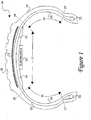
- Figure 1 displays a generally cross-sectional view of an exemplary pneumatic tire structure with integrated self-powered electronic components in accordance with the present subject matter
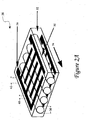
- Figure 2A displays a generally perspective view of a first exemplary piezoelectric structure for use with a power generation device in accordance with the present subject matter
- Figure 2B displays a generally perspective view of a second exemplary piezoelectric structure for use with a power generation device in accordance with the present subject matter
- Figure 2C displays a generally exploded perspective view of a third exemplary piezoelectric structure for use with a power generation device in accordance with the present subject matter
- Figure 3 provides a schematic representation of additional exemplary aspects of a power generation device in accordance with the present subject matter, particularly regarding an exemplary power conditioning module;
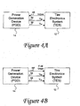
- Figure 4A provides a block diagram representation of exemplary integrated self-powered electronics including a power generation device and a tire electronics system and exemplary interaction thereof in accordance with the present subject matter;
- Figure 4B provides a block diagram representation of exemplary integrated self-powered electronics including a power generation device and a tire electronics system and alternative exemplary interaction thereof in accordance with the present subject matter;
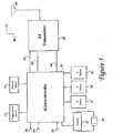
- Figure 5 provides a block diagram representation of an exemplary tire electronics system in accordance with the disclosed technology
- Figure 6 provides a block diagram representation of an exemplary remote receiver configuration in accordance with the present subject matter
- Figures 7A, 7B, 7C and 7D illustrate respective exemplary configurations of multiple piezoelectric elements in stacked combination for use in a power generation device in accordance with the present subject matter
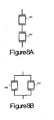
- Figures 8A and 8B respectively illustrate exemplary configurations of multiple piezoelectric elements in series and parallel combination for use in a power generation device in accordance with the present subject matter.
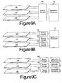
- Figures 9A, 9B and 9C respectively illustrate exemplary configurations of multiple piezoelectric elements coupled to one or more energy storage devices and one or more application electronics modules in accordance with exemplary power generation device and tire electronics system embodiments of the present technology.
- a power generation device utilizes piezoelectric technology to convert mechanical strain associated with tire flexure to electric current that is then conditioned and stored in an energy storage device. Sufficient accumulations of such stored energy can then power electronic systems, examples of which include components for identifying various physical tire parameters as well as radio frequency (RF) transmission devices.
- RF radio frequency
- a power generation device in accordance with the disclosed technology generally includes two exemplary components, a piezoelectric structure and a power conditioning module. Aspects of various exemplary piezoelectric structures are described with reference to Figures 2A, 2B and 2C and an exemplary power conditioning module (with energy storage device) is presented in and discussed with reference to Figure 3. Additional aspects related to exemplary configurations of one or more piezoelectric elements in a power generation device are illustrated in Figures 7A-7D, respectively, and in Figures 8A and 8B.
- the output of the power conditioning module may then preferably be used to power electronics systems within a tire or wheel assembly.
- An example of a tire electronics system, including sensors, a microcontroller, and an RF transmitter is presented in Figure 5.
- Figure 1 provides a generally cross-sectional view of an exemplary pneumatic tire assembly 10 with integrated self-powered electronic components 12 in accordance with the present subject matter.
- a power generation device (PGD) 14 is preferably provided in conjunction with electronic components internal to a tire structure 16 such that the electronics components are self-powered within the tire assembly 10.
- the capabilities of the subject power generation device with piezoelectric materials offer numerous advantages over conventional techniques for providing power within a tire assembly.
- Antenna beam power scavenging techniques are no longer one of limited options to choose from for powering tire electronics. As such, the functional capabilities of many types of tire electronics are generally increased.
- the option of utilizing batteries for power generation is no longer essential, thus avoiding costly and cumbersome battery replacement.
- the presently disclosed technology provides for a power generation device that enables antenna beam power and batteries to be eliminated, it should be appreciated that a power generation device could employ a hybrid combination of piezoelectric technology and/or batteries and/or antenna beam scavenging to power different selected electronic components within a wheel assembly.
- a typical tire structure 16 is characterized by a crown 15 which supports an exterior tread portion 18 and sidewalls 20 that extend to bead portions 22.
- Sidewalls 20 generally extend between section lines 17 and 19 and the tire crown 15 generally extends between the two section lines 19.
- Tire beads 22 are generally provided such that the tire structure 16 can be effectively seated to the rim of a wheel assembly.
- An inner liner of air-impermeable material forms the interior surface of the tire, including interior crown surface 24 and interior sidewall surfaces 26.
- a carcass 23 extends between beads 22 across sidewall portions 20 and crown 15, and under inflation pressure defines the tire's shape and transmits forces for traction and steering.
- Belt package 21 is provided within tire structure 16 generally along the crown 15.
- PGD 14 as illustrated in the exemplary tire assembly embodiment of Figure 1, may be mounted to the interior crown surface 24 of tire structure 16. This location is generally well-suited for actuation of the piezoelectric device within PGD 14 as the exterior tread portion 18 moves along a ground surface and results in flexure of the tire structure 16. This tire flexure coupled with the general mechanical vibrations as the tire assembly 10 moves along a surface enable piezoelectric device within the power generation device 14 to generate electric current, which is then conditioned and stored in an energy storage device for powering the tire electronics 12.
- the interior crown surface 24 is a logical location for mounting power generation device 14, it should be appreciated that PGD 14 may also be mounted to a location such as an interior sidewall surface 26.
- PGD 14 may offer less strain on the piezoelectric elements within the subject PGD 14 while still providing enough power generation for certain electronic applications.
- PGD 14 could be mounted and cured within tire structure 16, for example, between carcass 23 and the inner liner provided along surfaces 24 and/or 26.
- integral generally encompasses all possible locations, including being mounted on or in a tire structure.
- PGD 14 generally comprises two main components, a piezoelectric device and a power conditioning module.
- the piezoelectric device is subjected to mechanical strains caused by tire rotation, thereby generating charge in one or more piezoelectric elements (as should be understood by one of ordinary skill in the related art).
- This electric charge is then preferably provided to a power conditioning module where the resulting current is rectified, conditioned, and stored for use with power electronics.
- the piezoelectric device could comprise a variety of piezoelectric materials, including but not limited to barium titanate, polyvinylidene fluoride (PVDF), lead zirconate titanate (PZT) crystals, or PZT fibers.
- a particular type of piezoelectric material that may be utilized in accordance with the subject power generation device is a piezoelectric fiber composite structure, such as those disclosed in U.S. Patent Nos. 5,869,189 and 6,048,622 issued to Hagood, IV et al., hereby incorporated b y reference for all purposes.
- a similar example of such Active Fiber Composites (AFCs) that may be utilized in accordance with the present subject matter corresponds to "PiezoFlex" brand technology, such as offered for sale by Continuum Control Corporation.
- FIG. 2A displays an isometric view of a piezoelectric AFC structure 28 in accordance with exemplary aspects of the presently disclosed power generation device.
- a piezoelectric AFC structure 28 includes a plurality of piezoelectric fibers 30 that are unidirectionally aligned to provide actuation and stiffness of AFC structure 28.
- the fibers 30 are surrounded by a resin matrix 32 of epoxy or polymer, that provides a damage tolerance through load transfer mechanisms.
- the piezoelectric fibers have a common poling direction 34 transverse to their substantially co-parallel axial arrangement.
- Electrode layers are preferably provided on separate substrates along two opposing surfaces of the fiber/resin matrix configuration to provide electrical input and output to the AFC structure 28.
- electrode layers 36 are configured with an interdigital arrangement with alternating finger-to-finger polarity.
- Such interdigitated electrode layers 36 may be etched onto separate substrate layers (of polyimide or polyester, for example) using screen-printing techniques as known in the art and conductive ink such as silver-loaded epoxy.
- the alignment of the interdigital electrode configuration of Figure 2A is designed to enhance the directionality of the electromechanical response of the AFC structure 28, as well as provide for relatively high charge and coupling coefficients.
- the amount of resin matrix 32 between electrodes 36 and fibers 30 is preferably minimized to achieve greater performance capabilities.
- the orientation of the fibers in an AFC structure relative to a tire structure is a particular design factor in accordance with the subject technology.
- piezoelectric fibers are subjected to generally high tensile strains, but low compressive strains.
- Orienting the fiber direction along the radial direction of a tire couples the primary energy harvesting to the radial strains. This orientation is less likely to cause damage to fibers, but yields a potentially higher susceptibility of compressive depoling of the fibers.
- orienting a piezoelectric patch of a power generation device of the present subject matter radially versus circumferentially a long the summit of a tire structure may be determined based on the size of the patch and the specific tire environment to which it will be subjected. More particularly, optimal placement and orientation of a piezoelectric AFC structure may be based on factors such as maximum power desired per tire cycle, peak tensile and compressive strains along radial versus circumferential mounting directions, and strain uniformity over an AFC structure at given times.
- piezoelectric fibers may correspond to a variety of different PZT materials, including PZT 5A, PZT 5H, PZT 4, PZT 8, and PMN-33PT.
- PZT 5A, PZT 5H, PZT 4, PZT 8, and PMN-33PT Another specific design constraint corresponds to the diameter 38 of the piezoelectric fibers, which may typically be in a range from about three thousandths of an inch (mils) to about fifteen mils.
- Other specific dimensions that may be designed f or p articular applications include the width 40 and pitch 42 of the electrode fingers in interdigital layers 36.
- electrode finger width 40 corresponds to about twenty-five mils
- an exemplary range for electrode pitch 42 corresponds to from about twenty mils to about one-hundred mils.
- a specific example of an overall piezoelectric AFC structure for use in accordance with the present subject matter comprises interdigital electrodes with a forty-five mil electrode finger pitch and PZT-5A piezoelectric fibers with a ten mil diameter.
- a piezoelectric structure for use in a power generation device in accordance with the present subject matter may be considered for certain applications. For instance, there may be certain design constraints relative to the size and processing capabilities of a piezoelectric patch for integration within a tire structure.
- a PGD in accordance with the disclosed technology comprises a piezoelectric device mounted circumferentially along a tire summit along with an integrated power conditioning module.
- the PGD is preferably provided in an additional rubber or elastomer casing or supported on a rubber or fiberglass substrate when it is adhered to the tire interior to provide it with additional protection.
- a rubber casing or substrate additionally provides for facilitated adhesion of the PGD to a tire structure.
- the patch In order for the piezoelectric patch to be bonded to a rubber patch for adhering to a tire interior, the patch must generally be able to survive about one-hundred-seventy degrees Celsius for about thirty minutes while subjected to about twenty bar pressure and also to survive about one-hundred-fifty degrees Celsius for about sixty minutes at about twenty bar pressure. It should be appreciated that these specific constraints may change with the advancement of pertinent materials and adhesion technologies.
- a PGD in accordance with the present subject matter should preferably be able to withstand operating conditions from about negative forty degrees Celsius to about one-hundred-twenty-five degrees Celsius, a maximum tire speed of about one-hundred-sixty kph, and an endurance of either about ten years or seven-hundred-thousand miles.
- piezoelectric patch that may be utilized in PGD 14 in accordance with some embodiments of the present invention corresponds to generally solid piezoeceramic wafers.
- Such piezoceramic wafers may be s ingle-crystal or polycrystalline structures, including but not limited to wafers made of polycrystalline ferroelectric materials such as barium titanate (BaTiO 3 ) and lead zirconate titanate (PZT).
- Piezoelectric device 28' corresponds to one or more piezoceramic wafers provided in one of a unimorph, bimorph or stacked/sandwich arrangement and packaged within a protective skin 108.
- a unimorph arrangement generally corresponds to a single modular portion (i.e., layer) of piezoceramic material, which may be bonded to an inactive substrate in some embodiments.
- a bimorph arrangement generally corresponds to two modular portions (i.e., layers) of piezoceramic material that are bonded to opposing sides of a center metallic shim layer, and a stacked, or sandwich, arrangement corresponds to several piezoelectric elements provided adjacent to and coupled with one another. Bimorph and stacked arrangements may yield a higher level of generated charge versus amount of mechanical displacement than unimorph arrangements for certain applications.
- the protective casing 108 in which one or more piezoceramic wafers may be provided may serve as electrical insulation for the piezoceramic wafers as well as a defense against humidity and potentially harsh contaminants.
- the piezoceramic wafers may comprise specific PZT materials such as PZT-5A and/or PZT-5H.
- Distributed electrodes 110 may be made of such material such as nickel and may be provided on top and bottom surfaces of the assembly for coupling to pre-attached first and second electrical leads 112 and 114, respectively. Pins for connecting to leads 112 and 114 may be accessible via a connector element 120 for a reliable component with no soldered wires.
- Additional pins at connector element 120 may provide respective electrical connections 116 and 118 for poling the piezoceramic element(s) within piezoelectric device 28'.
- a specific example of the type of piezoelectric device represented in Figure 2B and that may be utilized in accordance with the present subject matter corresponds to "QuickPack" brand technology (e.g., ACX QuickPack-PowerAct QP15W), such as offered for sale by Midé Technology Corporation.
- FIG. 2C depicts a generally exploded perspective view of a piezoelectric element 28", including multiple layers provided in a generally stacked arrangement in which individual materials are layered on top of one another.
- a first layer in the layered composite comprising piezoelectric element 28" corresponds to a metal substrate layer 120, for example but not limited to a layer of stainless steel.
- Subsequent adhesive layers 122 are provided around an internal layer 124 of piezoelectric material.
- Piezoelectric layer 124 may correspond in some embodiments to a piezoceramic material such as PZT.
- Adhesive layers 122 may in some embodiments comprise a polyimide material or more specifically a high temperature thermoplastic polyimide (e.g., LaRCTM-SI brand material such as developed by NASA's Langley Research Center).
- a top layer 126 of piezoelectric element 28" comprises a metallic material such as but not limited to aluminum.
- Such multiple layers may be combined together by placing the entire assembly in an autoclave in which the multiple layers are heated, squeezed together, allowed to cook, and then cooled to around room temperature.
- the substrate layer 120 which is bonded to piezoceramic layer 124 acts to keep piezoceramic layer 124 in compression while is itself in a continuous state of tension. This induced pre-stress may cause the piezoelectric device to be ultimately formed in a slightly curved configuration, and allows the finished device to be subjected to much higher levels of mechanical deflection than some conventional piezoelectric devices without cracking.
- THUNDER brand technology
- Face Thunder Actuator 6R Face Thunder Actuator 6R
- THUNDER products generally correspond to Thin Layer Unimorph Ferroelectric Driver and Sensor devices that are made of multiple layers of material held together in a "sandwich-like" package with high strength bonding materials configured to provide internal pre-stresses.
- the adhesive layers 122 of piezoelectric element 28" hold the various device layers together despite relatively high internal stresses that are created during device manufacturing.
- piezoelectric elements discussed above for incorporation with a power generation device of the present subject matter as appreciated by one of ordinary skill in the art may be implemented, and that such variations are within the spirit and scope of the present invention.
- piezoelectric elements presented herein are generally rectangular in shape, it should be appreciated that piezoelectric elements of different shapes such as circular, square or otherwise may also be utilized. Additional modifications to the geometry, dimensions, material type, etc. of the piezoelectric elements are generally considered within the purview of one of ordinary skill in the art.
- FIGS 7A-7D illustrate respective exemplary configurations of how multiple elements 130 may be stacked vertically inside a tire PGD. Although only two piezoelectric elements 130 are illustrated in each configuration of Figures 7A-7D, it should be appreciated that more than two piezoelectric elements may be utilized.
- Pieozoelectric elements 130 may correspond to single-crystal or polycrystalline piezoceramic wafers, including but not limited to wafers made of polycrystalline ferroelectric materials such as barium titanate (BaTiO 3 ) and lead zirconate titanate (PZT).
- a center conductive shim layer may be provided in between each adjacent piezoelectric element 130, such as characteristic of some bimorph and stacked piezoelectric arrangements.
- FIGS 7A-7D illustrate different poling and displacement modes for the combined piezoelectric elements 130.
- Shorter arrows 132 and 134 within each piezoelectric element 130 represent the poling direction in each piezoelectric element, generally pointing from the positive to the negative poling electrode to which a high DC voltage would have been applied during manufacture of such pieozelectric elements 130.
- all such piezoelectric elements 130 are characterized by polarization vectors 132 and 134 that are generally parallel to the reference 3-axis.
- Figures 7B and 7D respectively illustrate configurations with both piezoelectric elements 130 having polarization vectors that are in-phase
- Figures 7A and 7D respectively illustrate configurations with both piezoelectric elements 130 having polarization vectors that are opposing, or out of phase
- the piezoelectric configurations of Figures 7A and 7B are both in d33 mode, wherein displacement forces (represented by arrows 136) correspond to an expansion in the same direction as the electrical field and the poling direction.
- the piezoelectric configurations of Figures 7C and 7D are both in d31 mode, wherein displacement forces (represented by arrows 138) correspond to a contraction perpendicular to the electrical field and the poling direction.
- Figures 7A-7D illustrate respective examples of how more piezoelectric material can be provided in a given strain field with the same footprint as a single piezoelectric element. Such an arrangement has the potential to yield more energy output for each rotation of a tire or wheel assembly, as the piezoelectric element(s) pass through the contact patch thereof
- piezoelectric elements 140 can be electrically connected in series (such as depicted in Figure 8A), in parallel (as depicted in Figure 8B), or in some combination thereof when more than two piezoelectric elements are combined.
- a series connection among piezoelectric elements 140 provides a generally higher voltage and lower current output than a single piezoelectric element.
- Such a configuration, a s represented i n Figure 8 A, may b e especially useful for sensing applications, such as detection of tire revolutions as a piezoelectric element passes through the contact patch of a tire or wheel assembly.
- a parallel connection among piezoelectric elements 140 provides a generally lower voltage and higher current output, which may be especially useful in energy harvesting applications.
- Piezoelectric elements 140 may correspond to such specific piezoelectric elements 28, 28' and 28" as illustrated and discussed with reference to Figures 2A, 2B and 2C, respectively, or in other embodiments as piezoceramic wafers such as elements 130 depicted in Figures 7A-7D, respectively.
- the second main component of PGD 14, in addition to a piezoelectric element is a power conditioning module, an exemplary embodiment of which is represented in Figure 3.
- the major functionality of a power conditioning module in accordance with the present subject matter is to rectify, condition and store the electric charge that is generated in the piezoelectric structure 140.
- power conditioning modules may be particularly designed for different electronics applications for which power is harvested.
- the exemplary power conditioning module of Figure 3 is designed according to certain dynamic energy requirements.
- the exemplary power conditioning module of Figure 3 is designed such that the voltage output 44 is generally about five volts, the maximum ripple of output voltage 44 is within ⁇ ten mvolts, the minimum duty cycle of output voltage 44 is about sixty seconds, and the maximum duty cycle of output voltage 44 is about five seconds. Additional design requirements within which the exemplary power conditioning module embodiment of Figure 3 operates correspond to a maximum energy requirement into an electronics system of about four mJoules and a time duration for which an electronics system can operate between about twenty-five msec and about two-hundred msec, depending on the functionality of the electronics system.
- one or more piezoelectric elements 140 are connected in parallel with a rectifier, for example full-bridge rectifier 46.
- a rectifier for example full-bridge rectifier 46.
- Alternative rectifier configurations could correspond to a doubling rectifier or an N-stage voltage multiplier.
- the rectified signal from rectifier 46 is then stored in electrolytic capacitor 48.
- a specific example of an electrolytic capacitor 48 suitable for employment in the exemplary power conditioning module of Figure 3 corresponds to a Panasonic TEL series tantalum capacitor with a capacitance of about forty-seven ⁇ Farads.
- Other specific electrolytic capacitors may similarly be suitable for utilization as a storage element in accordance with the disclosed power conditioning module.
- Other energy storage elements such as rechargeable batteries or super capacitors, may provide a suitable alternative in certain applications as an energy storage device for a power conditioning module.
- an FET transistor 50 acts as a switch to release the stored energy in capacitor 48 to a voltage regulator 52.
- a voltage regulator suitable for use in the exemplary embodiment of Figure 3 is a dual- mode five-volt programmable micropower voltage regulator such as the MAX666 brand offered for sale by Maxim Integrated Products. Such a voltage regulator is ideally suited for electronics systems that may typically have been battery-powered systems, and effectively convert the voltage across capacitor 48 to a regulated five volt output voltage 44.
- a diffusion metal oxide semiconductor (DMOS) FET transistor 54 and zener diode 56 are additionally provided in the exemplary power conditioning module of Figure 3.
- transistors 50 and 54 are off, and the ground at the drain of transistor 54 is floating such that no output voltage 44 is provided.
- capacitor 48 charges to a sufficient voltage level (determined by zener diode 56 and the base-emitter junction of transistor 50)
- transistor 50 turns on, activating transistor 54 and latching transistor 50.
- capacitor 48 is allowed to discharge through the circuitry providing a five volt regulated output 44 to an electronics system.
- the electronics system sends a signal back at signal path 58, through resistor 60 and capacitor 6 2 to turn off field effect transistor (FET) 50 and deactivate transistor 54 such that energy can once again begin to accumulate on capacitor 48.
- FET field effect transistor
- FIG. 4A and 4B respectively, illustrate exemplary aspects of interaction between a PGD 14 and TES 12.
- PGD 14 continuously provides voltage "V dd " and ground “V ss " signals to TES 12 along with a "Fuel Gage” signal representative of the amount of energy stored in PGD 14.
- a microprocessor or other suitable electronic component can periodically activate itself and monitor the Fuel Gage signal from PGD 14. If a sufficient amount of energy is available in the energy storage device of PGD 14, then TES 12 w ill engage in a specified task. If a sufficient amount of energy i s not available, then TES 12 will go into a low power mode where it consumes less than about one ⁇ A of power. The Fuel Gage signal is thereafter periodically checked until energy accumulation is sufficient. This cycle of waiting for sufficient energy accumulation, engaging in a specified task, and returning to low power mode is preferably repeated in a continuous fashion as long as the tire is rotating at or above a given threshold speed.
- TES 12 could comprise a variety of different electronic applications depending on what sort of components are included in a tire or wheel assembly.
- a specific example of a tire electronic system 12 corresponds to a tire monitoring system, such as hereafter discussed with reference to Figure 5.
- the tire monitoring system of Figure 5 measures temperature and pressure within a tire structure and sends the results by means of a radio frequency (RF) transmitter 68 to a remote receiver location.
- RF radio frequency
- An example of respective transmitter and receiver modules for utilization with aspects of the disclosed technology corresponds to respective TX2 and RX2 brand UHF FM Data Transmitter and Receiver Modules such as offered for sale by Radiometrix Ltd.
- a five-volt power signal "V dd”, ground signal “V ss ", and either an "Active” or “Fuel Gage” signal as discussed with reference to Figures 4A and 4B are preferably provided from PGD 14 to a microcontroller 70.
- An example of a suitable microcontroller for use with the disclosed technology is a Microchip brand PIC16LF876 28-pin CMOS RISC microcontroller.
- Microcontroller 70 is activated when power is applied at input path 64 and then applies power to both temperature sensor 72 and pressure sensor 74 (as well as any additional sensors or appropriate electronic devices in TES 12).
- An example of a temperature sensor 72 suitable for utilization with the disclosed technology is a LM50 SOT-23 Single-Supply Centigrade Temperature Sensor such as offered for sale by National Semiconductor.
- An example of a pressure sensor 74 suitable for utilization with the disclosed technology is a Model 1471 PC Board Mountable Pressure Sensor such as offered for sale by ICSensors and Measurement Specialties Inc. Additional sensors 76, 78 and 80, respectively, may measure additional characteristics of a tire structure or corresponding wheel assembly.
- Yet another component of the exemplary TES embodiment 12 of Figure 5 corresponds to a rechargeable battery 81 that may also be configured to receive electric charge generated within piezoelectric structure 28 of PGD 14 and to store additional energy for the integrated tire electronics.
- Energy stored in battery 81 can typically be stored for a much longer period of time than in other storage devices such as exemplary capacitor 48.
- Energy stored in battery 81 can be provided to microcontroller 70 when not enough power is generated by actuation of the piezoelectric device. Such a situation could occur, for instance, when the vehicle is stationary or when the tires are removed from a vehicle.
- stored energy may be needed to power TES 12 when a ground crew checks the air pressure in stationary tires on a commercial airliner.
- battery 81 may serve to provide power to TES 12 such that information for managing tire inventories or retreads is available when a tire is removed from the vehicle.
- microcontroller 70 preferably includes an analog-to-digital (A/D) converter that receives information from sensors 72 through 80, respectively, and converts it to digital information.
- Microcontroller 70 also comprises memory, preferably non-volatile EEPROM, which stores a unique identification tag that provides sufficient information to identify the tire or wheel assembly. Such an identification variable may be especially useful in tracking tires and vehicles in commercial applications such as trucking fleets, airplanes, etc.
- microcontroller 70 preferably shuts off power to the sensors and turns on power to RF transmitter 68 at lines 82 and 84 respectively.
- the desired digitized information is then output on data line 86 to RF transmitter 68, where the data is modulated onto an FM carrier signal and transmitted via antenna 88 to a remote receiver location.
- a vehicle employing tire assemblies with self-powered electronics in accordance with the present subject matter are preferably equipped with a single receiver for obtaining the wirelessly transmitted information from each tire assembly.
- Figure 6 provides a block diagram representation of an exemplary remote receiver configuration 90 in accordance with the present subject matter.
- Receiver antenna 92 facilitates receipt of information transmitted from each wheel assembly and relays the information to RF receiver 94, where the received information is demodulated from its carrier signal and provided on path 96 to signal processor 98.
- a carrier detection signal is also provided from RF receiver 94 to signal processor 98 via signal path 100.
- the data outputted from RF receiver 94 and the carrier detection signal are preferably multiplied together in signal processor 98 such that a signal without spurious noise is obtained.
- This data signal with reduced error probability is then preferably routed to a driver circuit that converts the digital signal to a signal with voltage levels suitable for transmission via an RS232 interface 102 to a host computer 104.
- Terminal emulation software is preferably provided at host computer 104 such that the data received via RS232 interface 102 is converted to information readily usable by an end user, such as that provided on a readable display module.
- i t may b e desired to transmit other types of information other than temperature, pressure and identification to a remote location. Examples include the number of tire revolutions, amount of tire deflection, and vehicle speed.
- U.S. Patent No. 5,749,984 discloses other aspects of a tire monitoring system that may be employed with the present subject matter, and such patent is hereby incorporated by reference for all purposes.
- a tire electronics system may be coupled with a global positioning system (GPS) to pinpoint a vehicle's precise location.
- GPS global positioning system
- a piezoelectric PGD may alternatively be utilized to power light assemblies or feedback systems in a wheel assembly.
- the number of electronics applications capable of being powered in accordance with aspects of the disclosed technology are vastly numerous and should in no way be limiting to the present subject matter.
- piezoelectric elements 140 may be provided within a tire or wheel assembly. Such piezoelectric elements 140 may be positioned in close proximity to one another within a tire or wheel assembly or may be distributed at different locations throughout the tire or wheel assembly. Piezoelectric elements 140 may in some embodiments comprise such specific exemplary piezoelectric elements 28, 28' and 28" as illustrated and discussed with reference to Figures 2A, 2B and 2C, respectively, or in other embodiments may comprise piezoceramic wafers such as elements 130 depicted in Figures 7A-7D, respectively. Each piezoelectric element 140 of Figure 9A generates energy when passed through the contact patch of the tire or wheel assembly to which it is mounted.
- the piezoelectric elements 140 may be electrically connected in series or in parallel and are all coupled to a central energy storage module 142.
- Energy storage module 142 includes selected power conditioning circuitry, such as described in the example of Figure 3, including an energy storage device such as a capacitor or battery for storing the energy generated by respective piezoelectric elements 140.
- the single energy storage module 142 is further coupled to an electronics module such as TES 12, such that selected application electronics within TES 12 may receive power stored by energy storage module 142.
- the distributed piezoelectric elements 140 may be electrically connected in series or in parallel and are each respectively coupled to distinct local energy storage modules 142.
- Each energy storage module 142 includes selected power conditioning circuitry, such as described in the example of Figure 3, including an energy storage device such as a capacitor or battery for storing the energy generated by a respective piezoelectric elements 140.
- the multiple storage modules 142 may be connected electrically in series or parallel to deliver energy to a central electronics module such as TES 12, such that selected application electronics within TES 12 may receive power stored by the energy storage modules 142.
- each of the plurality of energy storage modules 142 may deliver energy to a respective local electronics module, such as TES 12.
- the plurality of local electronics modules 12 m ay b e distributed i n various locations throughout a tire or wheel assembly and may perform similar functions to one another or may be configured to perform different functions, such as to measure different parameters at distinct respective locations.
Applications Claiming Priority (2)
| Application Number | Priority Date | Filing Date | Title |
|---|---|---|---|
| US10/850,860 US7096727B2 (en) | 2002-05-10 | 2004-05-21 | System and method for generating electric power from a rotating tire's mechanical energy |
| US850860 | 2004-05-21 |
Publications (3)
| Publication Number | Publication Date |
|---|---|
| EP1598219A2 true EP1598219A2 (fr) | 2005-11-23 |
| EP1598219A3 EP1598219A3 (fr) | 2008-10-01 |
| EP1598219B1 EP1598219B1 (fr) | 2010-05-19 |
Family
ID=34936825
Family Applications (1)
| Application Number | Title | Priority Date | Filing Date |
|---|---|---|---|
| EP05011105A Not-in-force EP1598219B1 (fr) | 2004-05-21 | 2005-05-23 | Système pour la production d'énergie électrique à partir de l'énergie mécanique d'un pneumatique en rotation |
Country Status (10)
| Country | Link |
|---|---|
| US (1) | US7096727B2 (fr) |
| EP (1) | EP1598219B1 (fr) |
| JP (2) | JP5014590B2 (fr) |
| KR (1) | KR20060048112A (fr) |
| CN (1) | CN1699084B (fr) |
| AT (1) | ATE468235T1 (fr) |
| BR (1) | BRPI0501788A (fr) |
| DE (1) | DE602005021275D1 (fr) |
| RU (1) | RU2377137C2 (fr) |
| TW (1) | TW200538317A (fr) |
Cited By (9)
| Publication number | Priority date | Publication date | Assignee | Title |
|---|---|---|---|---|
| WO2007094948A1 (fr) * | 2006-02-14 | 2007-08-23 | Robert Bosch Gmbh | Dispositif collecteur d'energie moule par injection |
| FR2906418A1 (fr) * | 2007-01-18 | 2008-03-28 | Siemens Vdo Automotive Sas | Boitier electronique destine a etre monte sur une roue de vehicule en vue de la mesure d'au moins un parametre de fonctionnement de la dite roue de vehicule |
| WO2008062377A3 (fr) * | 2006-11-24 | 2008-11-06 | Encrea S R L | Générateur miniaturisé pour la production d'énergie électrique à partir de vibrations |
| ITFI20080191A1 (it) * | 2008-10-06 | 2010-04-07 | Encrea S R L | Generatore miniaturizzato a magneti oscillanti per la produzione di energia elettrica da vibrazioni |
| DE102007010780B4 (de) * | 2006-03-02 | 2016-01-28 | Continental Teves Ag & Co. Ohg | Reifenmodul mit piezoelektrischem Wandler |
| CN106183660A (zh) * | 2016-08-30 | 2016-12-07 | 温州华邦安全封条股份有限公司 | 一种胎压监测系统及其安装方法 |
| CN107517023A (zh) * | 2017-08-14 | 2017-12-26 | 西北工业大学 | 一种基于pvdf压电薄膜的运动自行车 |
| CN107521294A (zh) * | 2017-08-31 | 2017-12-29 | 江苏大学 | 一种汽车胎压监测系统的发电装置 |
| WO2021052957A1 (fr) | 2019-09-16 | 2021-03-25 | Apollo Tyres Global R&D B.V. | Pneumatique comportant un dispositif piézoélectrique |
Families Citing this family (70)
| Publication number | Priority date | Publication date | Assignee | Title |
|---|---|---|---|---|
| US7549327B2 (en) * | 2001-02-16 | 2009-06-23 | Automotive Technologies International, Inc. | Tire-mounted energy generator and monitor |
| US20060237109A1 (en) * | 2003-11-17 | 2006-10-26 | Anton Mangold | Holding device for fixing an electronic component |
| US7023100B2 (en) * | 2003-12-15 | 2006-04-04 | Glycon Technologies, L.L.C. | Method and apparatus for conversion of movement to electrical energy |
| AU2003296839A1 (en) * | 2003-12-29 | 2005-08-12 | Pirelli Pneumatici S.P.A. | Method and system for generating electrical energy within a vehicle tyre |
| DE102005007061A1 (de) * | 2005-02-16 | 2006-08-17 | Siemens Ag | Vorrichtung zur Energieversorgung |
| JP5027793B2 (ja) * | 2005-03-11 | 2012-09-19 | ソシエテ ド テクノロジー ミシュラン | タイヤ状態のための撓み特徴解析 |
| JP5101497B2 (ja) * | 2005-06-10 | 2012-12-19 | コンパニー ゼネラール デ エタブリッスマン ミシュラン | 電子装置パッケージ・ハウジングに取り付けられている圧電センサの使用 |
| WO2007040536A2 (fr) * | 2005-10-03 | 2007-04-12 | Michelin Recherche Et Technique S.A. | Systeme et procede servant a recueillir du courant electrique a partir de l'energie acoustique d'un pneu en rotation |
| US7260984B2 (en) * | 2005-10-05 | 2007-08-28 | Lv Sensors, Inc. | Power generation utilizing tire pressure changes |
| WO2007131227A2 (fr) * | 2006-05-05 | 2007-11-15 | Advanced Cerametrics, Inc. | Dispositif électronique portable autoalimenté |
| ITMI20061296A1 (it) | 2006-07-04 | 2008-01-05 | Campagnolo Srl | Metodo di controllo e sistema di carica di una unita' di alimentazione a batteria |
| WO2008012850A1 (fr) * | 2006-07-28 | 2008-01-31 | Pirelli Tyre S.P.A. | Roue pour véhicules |
| US8261798B2 (en) * | 2006-10-30 | 2012-09-11 | Michelin Recherche Et Technique S.A. | Polyurethaneurea system |
| US20080252174A1 (en) * | 2007-04-10 | 2008-10-16 | Advanced Cerametrics, Inc. | Energy harvesting from multiple piezoelectric sources |
| BRPI0812356A2 (pt) | 2007-05-29 | 2015-01-27 | Hawkinson Paul E Co | Testador de defeito de pneu |
| CN101754873B (zh) * | 2007-07-18 | 2014-03-05 | 倍耐力轮胎股份公司 | 用于在车轮轮胎内产生电能的方法和系统 |
| WO2009010082A1 (fr) * | 2007-07-18 | 2009-01-22 | Pirelli Tyre S.P.A. | Procédé et système pour la détermination des paramètres de fonctionnement d'un pneu pendant le fonctionnement d'un véhicule |
| FR2919226B1 (fr) * | 2007-07-24 | 2009-10-09 | Michelin Soc Tech | Pneumatique equipe pour la fixation d'un objet a sa paroi et son procede de fabrication. |
| CN101835638B (zh) * | 2007-10-15 | 2012-05-30 | 香港应用科技研究院有限公司 | 识别车辆车轮的方法和装置以及包括该方法和装置的车辆 |
| WO2010024819A1 (fr) | 2008-08-29 | 2010-03-04 | Societe De Technologie Michelin | Appareil à pneumatique 1-d |
| US8922100B2 (en) * | 2009-03-04 | 2014-12-30 | Honda Motor Co., Ltd. | Woven active fiber composite |
| US8171791B2 (en) * | 2009-05-13 | 2012-05-08 | Robert Bosch Gmbh | Rotation sensor with onboard power generation |
| US20110043161A1 (en) * | 2009-08-19 | 2011-02-24 | Carlos Manuel Artieda | Electric wheels |
| JP5660655B2 (ja) * | 2009-08-21 | 2015-01-28 | ローム株式会社 | 車両のタイヤ空気圧管理装置および空気圧情報を出力可能な車両用タイヤ |
| US20110156532A1 (en) * | 2009-12-24 | 2011-06-30 | Churchill David L | Integrated Piezoelectric Composite and Support Circuit |
| CN101860263A (zh) * | 2010-05-21 | 2010-10-13 | 浙江海洋学院 | 压电式轮胎发电装置 |
| US8725330B2 (en) | 2010-06-02 | 2014-05-13 | Bryan Marc Failing | Increasing vehicle security |
| US20120049692A1 (en) * | 2010-06-24 | 2012-03-01 | Boyd Stephen A | System for harvesting energy from motor vehicle surfaces and methods thereof |
| DE102010038136B4 (de) * | 2010-10-12 | 2015-12-17 | Huf Hülsbeck & Fürst Gmbh & Co. Kg | Reifenmodul und damit ausgestatteter Reifen |
| US20120112898A1 (en) * | 2010-11-05 | 2012-05-10 | San-Chuan Yu | Programmable tire-condition sensor having a flexible shell, its installation method and a tire carrying same |
| KR101326584B1 (ko) * | 2011-05-25 | 2013-11-07 | (주)코아칩스 | 전기에너지 수득 장치와 이를 구비한 타이어 및 이를 이용한 전력공급방법 |
| RU2474042C1 (ru) * | 2011-07-22 | 2013-01-27 | Учреждение Российской академии наук Институт проблем управления им. В.А. Трапезникова РАН | Способ получения электрической энергии от маломощных источников электропитания |
| CN102957338A (zh) * | 2011-08-29 | 2013-03-06 | 文仁信 | 车辆上的压电发电装置 |
| CN102358183B (zh) * | 2011-09-05 | 2015-07-08 | 郑乃时 | 一种充气轮胎回收压力能惯能的利用装置和方法及应用 |
| RU2480663C1 (ru) * | 2011-11-16 | 2013-04-27 | Федеральное государственное бюджетное учреждение "Национальный исследовательский центр "Курчатовский институт" | Способ стабилизации давления в трубопроводах |
| KR101369686B1 (ko) * | 2012-04-30 | 2014-03-04 | 쌍용자동차 주식회사 | 차량의 배터리 충전장치 및 그 방법 |
| JP5947698B2 (ja) * | 2012-10-23 | 2016-07-06 | 住友ゴム工業株式会社 | タイヤ発電装置 |
| CN103367629B (zh) * | 2012-11-06 | 2016-03-02 | 北京纳米能源与系统研究所 | 纳米发电机及其制备方法和纤维阵列制备方法 |
| CN102961109B (zh) * | 2012-11-07 | 2015-07-08 | 深圳市资福技术有限公司 | 一种可无线式充电的胶囊内窥镜 |
| JP6101983B2 (ja) * | 2012-12-27 | 2017-03-29 | 日本特殊陶業株式会社 | 発電回路およびこれを用いた発信装置 |
| US9304142B1 (en) * | 2013-03-12 | 2016-04-05 | A. Steve Gurganian | Energy harvesting zero-speed sensor device, method and system |
| CA2937759A1 (fr) * | 2014-02-24 | 2015-08-27 | Mc10, Inc. | Electronique conforme a indicateurs de deformation |
| WO2015174617A1 (fr) * | 2014-05-16 | 2015-11-19 | 서울대학교 산학협력단 | Émetteur sans fil fonctionnant à l'énergie générée par un élément piézoélectrique |
| KR101612456B1 (ko) | 2014-09-12 | 2016-04-14 | 한국세라믹기술원 | 압전 파이버 컴포지트 구조체 및 이를 이용한 압전 스피커 |
| US9694690B2 (en) * | 2014-09-28 | 2017-07-04 | Derek Barton Fisher | Method and apparatus for generation, transmission and storage of electric energy |
| KR101705963B1 (ko) * | 2015-01-26 | 2017-02-10 | 서울시립대학교 산학협력단 | 압전섬유를 이용하는 타이어코드와 스판덱스, 이를 이용하는 에너지 하베스팅 장치 및 그 제조방법 |
| US10365184B2 (en) | 2015-06-30 | 2019-07-30 | Paul E. Hawkinson Company | Electrical discharge testing system |
| US9935563B2 (en) * | 2015-08-05 | 2018-04-03 | Nxp Usa, Inc. | Electrical energy generation within a vehicle tire |
| KR101795915B1 (ko) * | 2016-03-18 | 2017-11-10 | 서울시립대학교 산학협력단 | 압전섬유를 이용하는 타이어코드와 스판덱스, 이를 이용하는 에너지 하베스팅 장치 및 그 제조방법 |
| US10118696B1 (en) | 2016-03-31 | 2018-11-06 | Steven M. Hoffberg | Steerable rotating projectile |
| KR102578823B1 (ko) * | 2016-05-10 | 2023-09-15 | 삼성전자주식회사 | 마찰전기 발전기 |
| US10938328B2 (en) * | 2016-06-22 | 2021-03-02 | General Electric Company | Harvesting energy from composite aircraft engine components |
| US10243136B2 (en) * | 2016-08-22 | 2019-03-26 | Masoud Ghanbari | Piezoelectric energy harvesting system from vehicle's tires |
| FR3067978B1 (fr) * | 2017-06-23 | 2019-07-26 | Compagnie Generale Des Etablissements Michelin | Dispositif d'evaluation de la deformation d'une enveloppe pneumatique |
| US20190092104A1 (en) * | 2017-09-27 | 2019-03-28 | Nxp Usa, Inc. | Motion triggered system power up |
| JP7052366B2 (ja) | 2018-01-18 | 2022-04-12 | 横浜ゴム株式会社 | タイヤ情報取得装置 |
| FR3077385B1 (fr) * | 2018-01-30 | 2020-06-05 | Continental Automotive France | Unite electronique de mesure de parametres de fonctionnement d'une roue de vehicule adaptee pour etre positionnee sur la face interne d'une bande de roulement d'un pneumatique |
| US11712637B1 (en) | 2018-03-23 | 2023-08-01 | Steven M. Hoffberg | Steerable disk or ball |
| FR3083005B1 (fr) * | 2018-06-21 | 2020-11-20 | Michelin & Cie | Dispositif en matrice elastomere comprenant des charges piezoelectriques et des electrodes |
| FR3082781B1 (fr) * | 2018-06-21 | 2022-12-02 | Michelin & Cie | Pneumatique comprenant un composite piezoelectrique |
| CN110733299A (zh) * | 2018-07-18 | 2020-01-31 | 住友橡胶工业株式会社 | 轮胎组装体、轮胎的监控系统和方法 |
| KR102095473B1 (ko) * | 2018-08-13 | 2020-03-31 | 금호타이어 주식회사 | 냉각성을 구비한 타이어 |
| US11446966B2 (en) | 2019-03-27 | 2022-09-20 | Lyten, Inc. | Tires containing resonating carbon-based microstructures |
| US11491830B2 (en) * | 2019-04-18 | 2022-11-08 | Bridgestone Americas Tire Operations, Llc | System and method for harvesting energy for an electronic device, and a tire configured for use with the same |
| US11001109B1 (en) | 2019-05-13 | 2021-05-11 | Unicus Innovations Llc | Tire stem having breather |
| US11571936B1 (en) | 2019-05-13 | 2023-02-07 | Unicus Innovations Llc | Self contained tire inflator |
| TWM609142U (zh) * | 2019-11-27 | 2021-03-11 | 財團法人工業技術研究院 | 發電感測傳輸裝置 |
| CN112606636A (zh) * | 2021-02-01 | 2021-04-06 | 桂林电子科技大学 | 一种汽车轮胎的无源监测系统 |
| RU206286U1 (ru) * | 2021-04-26 | 2021-09-03 | Николай Иванович Филин | Устройство зарядки аккумулятора электромобиля |
| US11733126B2 (en) | 2021-07-07 | 2023-08-22 | Paul E. Hawkinson Company | Tire defect detection system that images localized cooling at a defect |
Citations (4)
| Publication number | Priority date | Publication date | Assignee | Title |
|---|---|---|---|---|
| US4300119A (en) * | 1979-09-06 | 1981-11-10 | Facet Enterprises, Inc. | Power generator for telemetry transmitter |
| EP0641679A1 (fr) * | 1993-09-02 | 1995-03-08 | Bayerische Motoren Werke Aktiengesellschaft | Dispositif de surveillance de pression du pneumatique d'un véhicule avec un palpeur |
| US6438193B1 (en) * | 1998-07-10 | 2002-08-20 | Wen H. Ko | Self-powered tire revolution counter |
| WO2003095245A1 (fr) * | 2002-05-10 | 2003-11-20 | Societe De Technologie Michelin | Systeme de production d'energie electrique a partir de l'energie mecanique d'un pneumatique en rotation, par le biais de materiaux piezo-electriques renforces |
Family Cites Families (25)
| Publication number | Priority date | Publication date | Assignee | Title |
|---|---|---|---|---|
| US3760351A (en) | 1971-07-02 | 1973-09-18 | S Thomas | Apparatus and process for developing electromagnetic energy from tire flexure |
| US4061200A (en) | 1976-01-12 | 1977-12-06 | Thompson Joseph A | Vehicular energy generation system |
| US4160234A (en) * | 1976-03-29 | 1979-07-03 | Gould Inc. | Abnormal tire condition sensing system |
| US4510484A (en) | 1983-03-28 | 1985-04-09 | Imperial Clevite Inc. | Piezoelectric reed power supply for use in abnormal tire condition warning systems |
| US4862486A (en) | 1987-11-16 | 1989-08-29 | Wing J Keith | Revolution counter attached to tires |
| US5457447A (en) | 1993-03-31 | 1995-10-10 | Motorola, Inc. | Portable power source and RF tag utilizing same |
| US5473938A (en) * | 1993-08-03 | 1995-12-12 | Mclaughlin Electronics | Method and system for monitoring a parameter of a vehicle tire |
| US5570286A (en) * | 1993-12-23 | 1996-10-29 | Lord Corporation | Regenerative system including an energy transformer which requires no external power source to drive same |
| US5869189A (en) | 1994-04-19 | 1999-02-09 | Massachusetts Institute Of Technology | Composites for structural control |
| US5741883A (en) | 1994-12-16 | 1998-04-21 | The United States Of America As Represented By The Administrator Of The National Aeronautics And Space Administration | Tough, soluble, aromatic, thermoplastic copolyimides |
| US5632841A (en) | 1995-04-04 | 1997-05-27 | The United States Of America As Represented By The Administrator Of The National Aeronautics And Space Administration | Thin layer composite unimorph ferroelectric driver and sensor |
| GB2307044A (en) | 1995-11-07 | 1997-05-14 | John Michael Jessop | Tyre mileage monitoring apparatus and method |
| US5749984A (en) | 1995-12-29 | 1998-05-12 | Michelin Recherche Et Technique S.A. | Tire monitoring system and method |
| JP3626269B2 (ja) * | 1996-02-29 | 2005-03-02 | 横浜ゴム株式会社 | トランスポンダ装着タイヤ |
| US5781104A (en) | 1996-12-23 | 1998-07-14 | Huang; Tien-Tsai | Pressure gauge with self-generating power capability for a tire pressure indicator |
| GB9709962D0 (en) | 1997-05-17 | 1997-07-09 | Sun Electric Uk Ltd | Method and apparatus for tyre pressure determination |
| JP3878280B2 (ja) * | 1997-05-27 | 2007-02-07 | 横浜ゴム株式会社 | タイヤ装着用トランスポンダ及びトランスポンダ装着タイヤ |
| US6175302B1 (en) | 1999-04-02 | 2001-01-16 | Tien-Tsai Huang | Tire pressure indicator including pressure gauges that have a self-generating power capability |
| US6959593B2 (en) | 2000-03-16 | 2005-11-01 | Pirelli Pneumatici S.P.A. | System, tire, wheel, vehicle, and method for determining the behavior of a tire in motion |
| ATE356442T1 (de) | 2000-04-18 | 2007-03-15 | Pirelli | Piezoelektrischer generator für sensoren in fahrzeugreifen |
| DE10133493A1 (de) | 2001-07-10 | 2003-01-23 | Philips Corp Intellectual Pty | Anordnung zur Betriebsspannungserzeugung für eine elektrische Baugruppe eines Fahrzeugs |
| US7081693B2 (en) * | 2002-03-07 | 2006-07-25 | Microstrain, Inc. | Energy harvesting for wireless sensor operation and data transmission |
| US6807853B2 (en) * | 2002-05-10 | 2004-10-26 | Michelin Recherche Et Technique S.A. | System and method for generating electric power from a rotating tire's mechanical energy using piezoelectric fiber composites |
| US6847126B2 (en) * | 2003-02-25 | 2005-01-25 | Michelin Recherche Et Technique S.A. | System and method for harvesting electric power from a rotating tire's static electricity |
| JP4367909B2 (ja) * | 2003-09-09 | 2009-11-18 | 横浜ゴム株式会社 | タイヤ接地力検知装置及び空気入りタイヤ |
-
2004
- 2004-05-21 US US10/850,860 patent/US7096727B2/en not_active Expired - Lifetime
-
2005
- 2005-04-21 TW TW94112653A patent/TW200538317A/zh unknown
- 2005-05-20 BR BRPI0501788 patent/BRPI0501788A/pt not_active IP Right Cessation
- 2005-05-20 RU RU2005115412A patent/RU2377137C2/ru not_active IP Right Cessation
- 2005-05-21 KR KR1020050044322A patent/KR20060048112A/ko not_active Application Discontinuation
- 2005-05-23 CN CN2005100722136A patent/CN1699084B/zh not_active Expired - Fee Related
- 2005-05-23 JP JP2005150240A patent/JP5014590B2/ja not_active Expired - Fee Related
- 2005-05-23 EP EP05011105A patent/EP1598219B1/fr not_active Not-in-force
- 2005-05-23 AT AT05011105T patent/ATE468235T1/de not_active IP Right Cessation
- 2005-05-23 DE DE200560021275 patent/DE602005021275D1/de active Active
-
2012
- 2012-03-07 JP JP2012050776A patent/JP5313381B2/ja not_active Expired - Fee Related
Patent Citations (4)
| Publication number | Priority date | Publication date | Assignee | Title |
|---|---|---|---|---|
| US4300119A (en) * | 1979-09-06 | 1981-11-10 | Facet Enterprises, Inc. | Power generator for telemetry transmitter |
| EP0641679A1 (fr) * | 1993-09-02 | 1995-03-08 | Bayerische Motoren Werke Aktiengesellschaft | Dispositif de surveillance de pression du pneumatique d'un véhicule avec un palpeur |
| US6438193B1 (en) * | 1998-07-10 | 2002-08-20 | Wen H. Ko | Self-powered tire revolution counter |
| WO2003095245A1 (fr) * | 2002-05-10 | 2003-11-20 | Societe De Technologie Michelin | Systeme de production d'energie electrique a partir de l'energie mecanique d'un pneumatique en rotation, par le biais de materiaux piezo-electriques renforces |
Cited By (12)
| Publication number | Priority date | Publication date | Assignee | Title |
|---|---|---|---|---|
| WO2007094948A1 (fr) * | 2006-02-14 | 2007-08-23 | Robert Bosch Gmbh | Dispositif collecteur d'energie moule par injection |
| US8225471B2 (en) | 2006-02-14 | 2012-07-24 | Robert Bosch Gmbh | Injection molded energy harvesting device |
| DE102007010780B4 (de) * | 2006-03-02 | 2016-01-28 | Continental Teves Ag & Co. Ohg | Reifenmodul mit piezoelektrischem Wandler |
| WO2008062377A3 (fr) * | 2006-11-24 | 2008-11-06 | Encrea S R L | Générateur miniaturisé pour la production d'énergie électrique à partir de vibrations |
| FR2906418A1 (fr) * | 2007-01-18 | 2008-03-28 | Siemens Vdo Automotive Sas | Boitier electronique destine a etre monte sur une roue de vehicule en vue de la mesure d'au moins un parametre de fonctionnement de la dite roue de vehicule |
| ITFI20080191A1 (it) * | 2008-10-06 | 2010-04-07 | Encrea S R L | Generatore miniaturizzato a magneti oscillanti per la produzione di energia elettrica da vibrazioni |
| WO2010041186A1 (fr) * | 2008-10-06 | 2010-04-15 | Encrea S.R.L. | Générateur miniaturisé pourvu d’aimants oscillants pour la production d’énergie électrique à partir de vibrations |
| US8593017B2 (en) | 2008-10-06 | 2013-11-26 | Pirelli Tyre S.P.A. | Miniaturized generator with oscillating magnets for the production of electric energy from vibrations |
| CN106183660A (zh) * | 2016-08-30 | 2016-12-07 | 温州华邦安全封条股份有限公司 | 一种胎压监测系统及其安装方法 |
| CN107517023A (zh) * | 2017-08-14 | 2017-12-26 | 西北工业大学 | 一种基于pvdf压电薄膜的运动自行车 |
| CN107521294A (zh) * | 2017-08-31 | 2017-12-29 | 江苏大学 | 一种汽车胎压监测系统的发电装置 |
| WO2021052957A1 (fr) | 2019-09-16 | 2021-03-25 | Apollo Tyres Global R&D B.V. | Pneumatique comportant un dispositif piézoélectrique |
Also Published As
| Publication number | Publication date |
|---|---|
| TW200538317A (en) | 2005-12-01 |
| RU2377137C2 (ru) | 2009-12-27 |
| RU2005115412A (ru) | 2006-11-27 |
| US20040211250A1 (en) | 2004-10-28 |
| JP5014590B2 (ja) | 2012-08-29 |
| CN1699084A (zh) | 2005-11-23 |
| EP1598219A3 (fr) | 2008-10-01 |
| JP5313381B2 (ja) | 2013-10-09 |
| CN1699084B (zh) | 2011-03-30 |
| BRPI0501788A (pt) | 2006-01-24 |
| JP2005335692A (ja) | 2005-12-08 |
| DE602005021275D1 (de) | 2010-07-01 |
| JP2012126396A (ja) | 2012-07-05 |
| KR20060048112A (ko) | 2006-05-18 |
| ATE468235T1 (de) | 2010-06-15 |
| EP1598219B1 (fr) | 2010-05-19 |
| US7096727B2 (en) | 2006-08-29 |
Similar Documents
| Publication | Publication Date | Title |
|---|---|---|
| EP1598219B1 (fr) | Système pour la production d'énergie électrique à partir de l'énergie mécanique d'un pneumatique en rotation | |
| EP1650057B1 (fr) | Systèm et procédure pour la production d'énergie electrique a partir de l'énergie méchanique d'un pneumatique en rotation | |
| US6807853B2 (en) | System and method for generating electric power from a rotating tire's mechanical energy using piezoelectric fiber composites | |
| EP1506101B1 (fr) | Systeme pour la production d'energie electrique a partir de l'energie mecanique d'un pneumatique en rotation, par le biais de materiaux piezo-electriques renforces | |
| US7047800B2 (en) | Piezoelectric ceramic fibers having metallic cores | |
| US7138911B2 (en) | Power conversion from piezoelectric source with multi-stage storage | |
| US8166809B2 (en) | In-tire multi-element piezoelectric sensor | |
| EP1612059A1 (fr) | Conversation d'énergie d'une source piézo-électrique | |
| EP1897078B1 (fr) | Couplage inductif de signaux de dispositif piézoélectrique | |
| EP1985000A2 (fr) | Systeme et procede de production d'energie electrique a partir des tensions mecaniques dans un systeme de suspension de vehicule |
Legal Events
| Date | Code | Title | Description |
|---|---|---|---|
| PUAI | Public reference made under article 153(3) epc to a published international application that has entered the european phase |
Free format text: ORIGINAL CODE: 0009012 |
|
| AK | Designated contracting states |
Kind code of ref document: A2 Designated state(s): AT BE BG CH CY CZ DE DK EE ES FI FR GB GR HU IE IS IT LI LT LU MC NL PL PT RO SE SI SK TR |
|
| AX | Request for extension of the european patent |
Extension state: AL BA HR LV MK YU |
|
| PUAL | Search report despatched |
Free format text: ORIGINAL CODE: 0009013 |
|
| AK | Designated contracting states |
Kind code of ref document: A3 Designated state(s): AT BE BG CH CY CZ DE DK EE ES FI FR GB GR HU IE IS IT LI LT LU MC NL PL PT RO SE SI SK TR |
|
| AX | Request for extension of the european patent |
Extension state: AL BA HR LV MK YU |
|
| 17P | Request for examination filed |
Effective date: 20090401 |
|
| 17Q | First examination report despatched |
Effective date: 20090427 |
|
| AKX | Designation fees paid |
Designated state(s): AT BE BG CH CY CZ DE DK EE ES FI FR GB GR HU IE IS IT LI LT LU MC NL PL PT RO SE SI SK TR |
|
| RTI1 | Title (correction) |
Free format text: SYSTEM FOR GENERATING ELECTRIC POWER FROM A ROTATING TIRE'S MECHANICAL ENERGY |
|
| GRAP | Despatch of communication of intention to grant a patent |
Free format text: ORIGINAL CODE: EPIDOSNIGR1 |
|
| GRAS | Grant fee paid |
Free format text: ORIGINAL CODE: EPIDOSNIGR3 |
|
| GRAA | (expected) grant |
Free format text: ORIGINAL CODE: 0009210 |
|
| AK | Designated contracting states |
Kind code of ref document: B1 Designated state(s): AT BE BG CH CY CZ DE DK EE ES FI FR GB GR HU IE IS IT LI LT LU MC NL PL PT RO SE SI SK TR |
|
| REG | Reference to a national code |
Ref country code: GB Ref legal event code: FG4D |
|
| REG | Reference to a national code |
Ref country code: CH Ref legal event code: EP |
|
| REG | Reference to a national code |
Ref country code: IE Ref legal event code: FG4D |
|
| REF | Corresponds to: |
Ref document number: 602005021275 Country of ref document: DE Date of ref document: 20100701 Kind code of ref document: P |
|
| REG | Reference to a national code |
Ref country code: NL Ref legal event code: VDEP Effective date: 20100519 |
|
| LTIE | Lt: invalidation of european patent or patent extension |
Effective date: 20100519 |
|
| PG25 | Lapsed in a contracting state [announced via postgrant information from national office to epo] |
Ref country code: LT Free format text: LAPSE BECAUSE OF FAILURE TO SUBMIT A TRANSLATION OF THE DESCRIPTION OR TO PAY THE FEE WITHIN THE PRESCRIBED TIME-LIMIT Effective date: 20100519 Ref country code: SE Free format text: LAPSE BECAUSE OF FAILURE TO SUBMIT A TRANSLATION OF THE DESCRIPTION OR TO PAY THE FEE WITHIN THE PRESCRIBED TIME-LIMIT Effective date: 20100519 Ref country code: ES Free format text: LAPSE BECAUSE OF FAILURE TO SUBMIT A TRANSLATION OF THE DESCRIPTION OR TO PAY THE FEE WITHIN THE PRESCRIBED TIME-LIMIT Effective date: 20100830 |
|
| PG25 | Lapsed in a contracting state [announced via postgrant information from national office to epo] |
Ref country code: FI Free format text: LAPSE BECAUSE OF FAILURE TO SUBMIT A TRANSLATION OF THE DESCRIPTION OR TO PAY THE FEE WITHIN THE PRESCRIBED TIME-LIMIT Effective date: 20100519 Ref country code: AT Free format text: LAPSE BECAUSE OF FAILURE TO SUBMIT A TRANSLATION OF THE DESCRIPTION OR TO PAY THE FEE WITHIN THE PRESCRIBED TIME-LIMIT Effective date: 20100519 Ref country code: IS Free format text: LAPSE BECAUSE OF FAILURE TO SUBMIT A TRANSLATION OF THE DESCRIPTION OR TO PAY THE FEE WITHIN THE PRESCRIBED TIME-LIMIT Effective date: 20100919 Ref country code: SI Free format text: LAPSE BECAUSE OF FAILURE TO SUBMIT A TRANSLATION OF THE DESCRIPTION OR TO PAY THE FEE WITHIN THE PRESCRIBED TIME-LIMIT Effective date: 20100519 |
|
| PG25 | Lapsed in a contracting state [announced via postgrant information from national office to epo] |
Ref country code: PL Free format text: LAPSE BECAUSE OF FAILURE TO SUBMIT A TRANSLATION OF THE DESCRIPTION OR TO PAY THE FEE WITHIN THE PRESCRIBED TIME-LIMIT Effective date: 20100519 Ref country code: MC Free format text: LAPSE BECAUSE OF NON-PAYMENT OF DUE FEES Effective date: 20100531 Ref country code: GR Free format text: LAPSE BECAUSE OF FAILURE TO SUBMIT A TRANSLATION OF THE DESCRIPTION OR TO PAY THE FEE WITHIN THE PRESCRIBED TIME-LIMIT Effective date: 20100820 Ref country code: CY Free format text: LAPSE BECAUSE OF FAILURE TO SUBMIT A TRANSLATION OF THE DESCRIPTION OR TO PAY THE FEE WITHIN THE PRESCRIBED TIME-LIMIT Effective date: 20100519 |
|
| REG | Reference to a national code |
Ref country code: CH Ref legal event code: PL |
|
| PG25 | Lapsed in a contracting state [announced via postgrant information from national office to epo] |
Ref country code: NL Free format text: LAPSE BECAUSE OF FAILURE TO SUBMIT A TRANSLATION OF THE DESCRIPTION OR TO PAY THE FEE WITHIN THE PRESCRIBED TIME-LIMIT Effective date: 20100519 Ref country code: DK Free format text: LAPSE BECAUSE OF FAILURE TO SUBMIT A TRANSLATION OF THE DESCRIPTION OR TO PAY THE FEE WITHIN THE PRESCRIBED TIME-LIMIT Effective date: 20100519 Ref country code: EE Free format text: LAPSE BECAUSE OF FAILURE TO SUBMIT A TRANSLATION OF THE DESCRIPTION OR TO PAY THE FEE WITHIN THE PRESCRIBED TIME-LIMIT Effective date: 20100519 Ref country code: PT Free format text: LAPSE BECAUSE OF FAILURE TO SUBMIT A TRANSLATION OF THE DESCRIPTION OR TO PAY THE FEE WITHIN THE PRESCRIBED TIME-LIMIT Effective date: 20100920 |
|
| PG25 | Lapsed in a contracting state [announced via postgrant information from national office to epo] |
Ref country code: RO Free format text: LAPSE BECAUSE OF FAILURE TO SUBMIT A TRANSLATION OF THE DESCRIPTION OR TO PAY THE FEE WITHIN THE PRESCRIBED TIME-LIMIT Effective date: 20100519 Ref country code: CZ Free format text: LAPSE BECAUSE OF FAILURE TO SUBMIT A TRANSLATION OF THE DESCRIPTION OR TO PAY THE FEE WITHIN THE PRESCRIBED TIME-LIMIT Effective date: 20100519 Ref country code: CH Free format text: LAPSE BECAUSE OF NON-PAYMENT OF DUE FEES Effective date: 20100531 Ref country code: BE Free format text: LAPSE BECAUSE OF FAILURE TO SUBMIT A TRANSLATION OF THE DESCRIPTION OR TO PAY THE FEE WITHIN THE PRESCRIBED TIME-LIMIT Effective date: 20100519 Ref country code: SK Free format text: LAPSE BECAUSE OF FAILURE TO SUBMIT A TRANSLATION OF THE DESCRIPTION OR TO PAY THE FEE WITHIN THE PRESCRIBED TIME-LIMIT Effective date: 20100519 Ref country code: LI Free format text: LAPSE BECAUSE OF NON-PAYMENT OF DUE FEES Effective date: 20100531 |
|
| PLBE | No opposition filed within time limit |
Free format text: ORIGINAL CODE: 0009261 |
|
| STAA | Information on the status of an ep patent application or granted ep patent |
Free format text: STATUS: NO OPPOSITION FILED WITHIN TIME LIMIT |
|
| 26N | No opposition filed |
Effective date: 20110222 |
|
| GBPC | Gb: european patent ceased through non-payment of renewal fee |
Effective date: 20100819 |
|
| PG25 | Lapsed in a contracting state [announced via postgrant information from national office to epo] |
Ref country code: IE Free format text: LAPSE BECAUSE OF NON-PAYMENT OF DUE FEES Effective date: 20100523 |
|
| REG | Reference to a national code |
Ref country code: DE Ref legal event code: R097 Ref document number: 602005021275 Country of ref document: DE Effective date: 20110221 |
|
| PG25 | Lapsed in a contracting state [announced via postgrant information from national office to epo] |
Ref country code: GB Free format text: LAPSE BECAUSE OF NON-PAYMENT OF DUE FEES Effective date: 20100819 |
|
| PG25 | Lapsed in a contracting state [announced via postgrant information from national office to epo] |
Ref country code: LU Free format text: LAPSE BECAUSE OF NON-PAYMENT OF DUE FEES Effective date: 20100523 Ref country code: HU Free format text: LAPSE BECAUSE OF FAILURE TO SUBMIT A TRANSLATION OF THE DESCRIPTION OR TO PAY THE FEE WITHIN THE PRESCRIBED TIME-LIMIT Effective date: 20101120 Ref country code: BG Free format text: LAPSE BECAUSE OF FAILURE TO SUBMIT A TRANSLATION OF THE DESCRIPTION OR TO PAY THE FEE WITHIN THE PRESCRIBED TIME-LIMIT Effective date: 20100519 |
|
| PG25 | Lapsed in a contracting state [announced via postgrant information from national office to epo] |
Ref country code: TR Free format text: LAPSE BECAUSE OF FAILURE TO SUBMIT A TRANSLATION OF THE DESCRIPTION OR TO PAY THE FEE WITHIN THE PRESCRIBED TIME-LIMIT Effective date: 20100519 |
|
| PG25 | Lapsed in a contracting state [announced via postgrant information from national office to epo] |
Ref country code: BG Free format text: LAPSE BECAUSE OF FAILURE TO SUBMIT A TRANSLATION OF THE DESCRIPTION OR TO PAY THE FEE WITHIN THE PRESCRIBED TIME-LIMIT Effective date: 20100819 |
|
| REG | Reference to a national code |
Ref country code: FR Ref legal event code: PLFP Year of fee payment: 12 |
|
| REG | Reference to a national code |
Ref country code: FR Ref legal event code: PLFP Year of fee payment: 13 |
|
| REG | Reference to a national code |
Ref country code: FR Ref legal event code: PLFP Year of fee payment: 14 |
|
| PGFP | Annual fee paid to national office [announced via postgrant information from national office to epo] |
Ref country code: DE Payment date: 20180522 Year of fee payment: 14 |
|
| PGFP | Annual fee paid to national office [announced via postgrant information from national office to epo] |
Ref country code: FR Payment date: 20180522 Year of fee payment: 14 Ref country code: IT Payment date: 20180530 Year of fee payment: 14 |
|
| REG | Reference to a national code |
Ref country code: DE Ref legal event code: R119 Ref document number: 602005021275 Country of ref document: DE |
|
| PG25 | Lapsed in a contracting state [announced via postgrant information from national office to epo] |
Ref country code: DE Free format text: LAPSE BECAUSE OF NON-PAYMENT OF DUE FEES Effective date: 20191203 Ref country code: IT Free format text: LAPSE BECAUSE OF NON-PAYMENT OF DUE FEES Effective date: 20190523 |
|
| PG25 | Lapsed in a contracting state [announced via postgrant information from national office to epo] |
Ref country code: FR Free format text: LAPSE BECAUSE OF NON-PAYMENT OF DUE FEES Effective date: 20190531 |