EP1598201A2 - A paper position correction method for a printer - Google Patents
A paper position correction method for a printer Download PDFInfo
- Publication number
- EP1598201A2 EP1598201A2 EP05103517A EP05103517A EP1598201A2 EP 1598201 A2 EP1598201 A2 EP 1598201A2 EP 05103517 A EP05103517 A EP 05103517A EP 05103517 A EP05103517 A EP 05103517A EP 1598201 A2 EP1598201 A2 EP 1598201A2
- Authority
- EP
- European Patent Office
- Prior art keywords
- sheet
- paper
- marks
- distance
- Prior art date
- Legal status (The legal status is an assumption and is not a legal conclusion. Google has not performed a legal analysis and makes no representation as to the accuracy of the status listed.)
- Withdrawn
Links
Images




Classifications
-
- B—PERFORMING OPERATIONS; TRANSPORTING
- B41—PRINTING; LINING MACHINES; TYPEWRITERS; STAMPS
- B41J—TYPEWRITERS; SELECTIVE PRINTING MECHANISMS, i.e. MECHANISMS PRINTING OTHERWISE THAN FROM A FORME; CORRECTION OF TYPOGRAPHICAL ERRORS
- B41J11/00—Devices or arrangements of selective printing mechanisms, e.g. ink-jet printers or thermal printers, for supporting or handling copy material in sheet or web form
- B41J11/36—Blanking or long feeds; Feeding to a particular line, e.g. by rotation of platen or feed roller
- B41J11/42—Controlling printing material conveyance for accurate alignment of the printing material with the printhead; Print registering
-
- B—PERFORMING OPERATIONS; TRANSPORTING
- B41—PRINTING; LINING MACHINES; TYPEWRITERS; STAMPS
- B41J—TYPEWRITERS; SELECTIVE PRINTING MECHANISMS, i.e. MECHANISMS PRINTING OTHERWISE THAN FROM A FORME; CORRECTION OF TYPOGRAPHICAL ERRORS
- B41J2/00—Typewriters or selective printing mechanisms characterised by the printing or marking process for which they are designed
- B41J2/315—Typewriters or selective printing mechanisms characterised by the printing or marking process for which they are designed characterised by selective application of heat to a heat sensitive printing or impression-transfer material
- B41J2/32—Typewriters or selective printing mechanisms characterised by the printing or marking process for which they are designed characterised by selective application of heat to a heat sensitive printing or impression-transfer material using thermal heads
-
- B—PERFORMING OPERATIONS; TRANSPORTING
- B41—PRINTING; LINING MACHINES; TYPEWRITERS; STAMPS
- B41J—TYPEWRITERS; SELECTIVE PRINTING MECHANISMS, i.e. MECHANISMS PRINTING OTHERWISE THAN FROM A FORME; CORRECTION OF TYPOGRAPHICAL ERRORS
- B41J29/00—Details of, or accessories for, typewriters or selective printing mechanisms not otherwise provided for
- B41J29/38—Drives, motors, controls or automatic cut-off devices for the entire printing mechanism
- B41J29/393—Devices for controlling or analysing the entire machine ; Controlling or analysing mechanical parameters involving printing of test patterns
-
- B—PERFORMING OPERATIONS; TRANSPORTING
- B41—PRINTING; LINING MACHINES; TYPEWRITERS; STAMPS
- B41J—TYPEWRITERS; SELECTIVE PRINTING MECHANISMS, i.e. MECHANISMS PRINTING OTHERWISE THAN FROM A FORME; CORRECTION OF TYPOGRAPHICAL ERRORS
- B41J3/00—Typewriters or selective printing or marking mechanisms characterised by the purpose for which they are constructed
- B41J3/60—Typewriters or selective printing or marking mechanisms characterised by the purpose for which they are constructed for printing on both faces of the printing material
Definitions
- the present invention relates a printer kit, comprising a thermal printer having a print head, feeding means for feeding a sheet into the printer and movement monitoring means for outputting a movement signal indicative of the movement of the roller.
- a thermal printer may use a sheet of special paper (hereinafter, called heat reactive paper) that reacts with heat to display a predetermined colour.
- the thermal printer may use an ink ribbon that reacts with heat so as to transfer a predetermined colour on a sheet of ordinary paper.
- a device for driving the ink ribbon must be installed in the thermal printer. Accordingly, the structure of the thermal printer is more complicated and manufacturing costs of the thermal printer increases. Moreover, since the ink ribbon is a consumable, it must be frequently replaced. Thus, printing costs per page are high.
- a sheet of heat reactive paper 10 includes a base sheet 11 and ink layers 12 and 13 of a predetermined colour formed on both the first and second side of the base sheet 11.
- Each of the ink layers 12 and 13 may have either a single-layer structure representing a single colour or a multi-layer structure representing two or more colours.
- the ink layer 12 on the first side of the base sheet 11 may have a structure where two layers representing magenta (M) and cyan (C) are stacked, and the ink layer 13 on the second side of the base sheet 11 may have a single-layer structure representing yellow (Y).
- the base sheet 11 may be made of a transparent material.
- An example of the heat reactive paper 10 is disclosed in US-A-2003/0125206.
- a thermal printer using the heat reactive paper 10 includes a thermal printhead (TPH).
- the TPH includes a number of electrothermal devices located perpendicularly to the direction of the paper movement. The number of devices on the TPH is determined by the required resolution.
- Figure 2 illustrates a configuration of a known thermal printer.
- the known thermal printer includes a feeding roller 2 moving a sheet of heat reactive paper 1, a platen roller 3 supporting one side of the sheet of heat reactive paper 1 and a TPH 4 which forms an image on the sheet of heat reactive paper 1 when pressing against the platen roller 3.
- An idle roller 5 presses the sheet of heat reactive paper 1 toward the feeding roller 2.
- the sheet of heat reactive paper 1 When an image is formed on the sheet of heat reactive paper 1, the sheet of heat reactive paper 1 is pressed between the TPH 4 and the platen roller 3. This reduces the driving force provided by the feeding roller 2. In other words, as the sheet of heat reactive paper 1 slips, the feeding distance may be changed. Such paper slip deteriorates the quality of the printed image.
- the present invention provides a method of compensating for paper slip of heat reactive paper in a thermal printer.
- the present invention relates a printer kit, comprising a thermal printer having a print head, feeding means for feeding a sheet into the printer and movement monitoring means for outputting a movement signal indicative of the movement of the roller.
- a printer kit is characterised by a slip calibration sheet having a first calibration mark located thereon, wherein the first mark is spaced from a reference by a predetermined distance, and the printer comprising detection means for outputting a detection signal indicative of the detection of the reference and the first calibration mark on the slip calibration sheet; and a controller for calibrating for the slip in the printer on the basis of the detection signal and the movement signal.
- the thermal printer has first, second and third paths, through which a sheet of heat reactive paper 10 is moved.
- the first path is a paper feed path through which the sheet of heat reactive paper 10 is fed to the second path.
- the second path is where the sheet of heat reactive paper 10 is fed backward in a direction indicated by an arrow B and fed forward in a direction indicated by an arrow F to print an image on the sheet of heat reactive paper 10.
- the third path is where the sheet of heat reactive paper 10, on which an image is being printed, is held.
- the sheet of heat reactive paper 10 is fed back to the second path from the third path.
- the sheet of heat reactive paper 10 is discharged through the third path.
- a paper guide 65 is disposed between the first path and the third path.
- the paper guide 65 guides the sheet of paper 10 from the first path to the second path and also from the second path to the third path.
- the paper guide 65 guides the sheet of heat reactive paper 10 fed from the second path to the third path and prevents the sheet paper 10 from proceeding to the first path. Also, the paper guide 65 guides the sheet of heat reactive paper 10 from the first path to the second path. Since the the paper guide 65 is known, a detailed description is omitted.
- An image forming unit 50 is located along the second path and forms an image on the sheet of paper 10.
- the image is formed on both the first and second sides of the paper (i.e. the image forming process is carried out twice). It is understood that the process may be required more than twice.
- a thermal printhead (TPH) 51 and a platen roller 55 included in the image forming unit 50 must be held at predetermined positions. For example, when an image is formed on the first side of the sheet of heat reactive paper 10, the TPH 51 must be positioned at a location "C”. When the image is formed on the second side of the sheet of heat reactive paper 10, the TPH 51 must be positioned at a location "D".
- the position of the TPH 51 is changed by rotating the TPH 51 around the rotational axis of the platen roller 55.
- the position of the TPH 51 is changed when the sheet of heat reactive paper is not in the image forming unit 50, for example, before the sheet of paper 10 is fed from the first path, or when the sheet of paper 10 is not fed to the second path from the third path.
- the image is formed on the second side of the sheet of heat reactive paper 10 by the TPH 51, whose position has already been changed.
- a conveying unit 40 feeds the sheet of heat reactive paper 10. After the image is formed on the second side of the sheet of heat reactive paper 10, the sheet of heat reactive paper 10 proceeds further along the third path and is discharged from the thermal printer through a paper discharge unit 60.
- the conveying unit 40 includes a feeding roller 41 which feeds the sheet of heat reactive paper 10 and an idle roller 42 which presses the sheet of heat reactive paper 10 towards the feeding roller 41, thus sandwiching the paper 10 between the two rollers.
- a paper cassette 70 and a pickup roller 72 supplies the sheets of paper.
- the paper discharge unit 60 includes a discharge roller 61 and an idle roller 62.
- the discharge roller 61 and the pickup roller 72 may be integrated into a single roller performing the combined functions of both the discharge roller 61 and the pickup roller 72.
- the sheet of heat reactive paper 10 which is sandwiched between the platen roller 55 and the TPH 51 is driven by the feeding roller 41.
- a sensor 53 detects marks on the sheet of heat reactive paper 10.
- An optical sensor may be used as the sensor 53.
- the sheet of heat reactive paper 10 is fed backward in the direction indicated by arrow B and fed forward in a printing direction indicated by arrow F.
- An encoder disk wheel 45 is mounted along an outer circumference of one side of the feeding roller 41. Slits 45a are formed along the edge of the encoder disk wheel 45 and are spaced at regular intervals.
- a rotary encoder sensor 46 includes a light source 46a and a light receiving unit 46b, which are mounted on both sides of the slit 45a.
- the light source 46a of the rotary encoder sensor 46 emits light at a regular speed and the light receiving unit 46b generates a pulse whenever light is received through the slit 45a.
- a controlling unit 80 measures the distance that the sheet of heat reactive paper 10 is moved by the feeding roller 41. This is achieved by counting the number of pulses.
- the controlling unit 80 also controls a driving motor 47 to control the distance that the sheet of heat reactive paper 10 is moved by the feeding roller 41.
- a duplex printing apparatus includes a rotation unit 57 and a unit for vertical movement 59.
- the rotation unit 57 rotates the TPH 51 and the platen roller 55 to print an image on the second side of the sheet of heat reactive paper 10 after an image has been printed on the first side of the sheet of heat reactive paper 10.
- the unit for vertical movement 59 moves the TPH 51 a predetermined distance away from or closer to the printing path.
- the unit for vertical movement 59 is used to separate the TPH 51 a predetermined distance, for example 1-2mm, away from the platen roller 55 such that the sheet of heat reactive paper 10 passes between the TPH 51 and the platen roller 55 without hindrance.
- Table 1 shows a result of measuring a paper slip distance when an image is printed on the sheet of heat reactive paper 10 using the duplex printing apparatus of Figure 4.
- the first side denotes an upper side of the sheet of heat reactive paper 10 and the second side denotes that an image was printed on the lower side of the sheet of heat reactive paper 10.
- the measurement indicates data obtained by averaging five measurements.
- the paper slip distance was obtained by dividing the length of the print region of the sheet of paper 10 into 6 inch segments.
- the actual distance that the sheet of heat reactive paper 10 is moved by the feeding roller 41 is shorter than the target distance.
- the paper slip distance of the sheet of heat reactive paper 10 may be changed according to the state of the feeding roller 41, the positions of the TPH 51 and the platen roller 55, and the age of the TPH 51 and the platen roller 55.
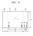
- the sheet of heat reactive paper 10 is divided into a print region PR, and first and second trim regions TR1 and TR2 that are trimmed after printing is completed.
- the length D1 of the print region PR is preferably six inches (approx. 15.2 cm) and the length D4 of the print region PR is preferably four inches (approx. 10.2 cm).
- the length D2 of the first trim region TR1 is preferably roughly one inch (approx. 2.5cm), and the length D3 of the second trim region TR2 is preferably one third of an inch (approx. 0.85cm).
- the direction indicated by arrow F is the forward direction which the paper moves during printing. Reference numerals M1 through M4, D5, and D7 will be described later.
- First and second marks M1 and M2 may be printed on the paper in advance. These marks are spaced apart by a predetermined distance (D5 of Figure 6) in the direction moved by the paper. The marks are made on the print region PR of the paper 10.
- the pickup roller 72 picks up a sheet of heat reactive paper 10 and moves the sheet of heat reactive paper 10 to the first path (operation 102).
- This command may come from the printer or a computer to which the printer is connected.
- the sheet of heat reactive paper 10 that enters the first path is guided to the feeding roller 41 by the paper guide 65.
- the feeding roller 41 then feeds the sheet of heat reactive paper 10 back to the second path as illustrated in Figure 8A (operation 103).
- the TPH 51 is separated from the platen roller 55 by a predetermined amount using the unit of vertical movement 59 ( Figure 5) allowing the paper to be located between the TPH 51 and the roller 55.
- the sheet of heat reactive paper 10 which enters the second path is fed back so that the entire print region PR of the sheet of heat reactive paper 10 is printed.
- the rotary encoder sensor 46 detects the rotation of the rotary encoder wheel 45 and generates a pulse signal. When the rotary encoder sensor 46 transmits the pulse signal to the controlling unit 80, the controlling unit 80 counts the pulse signals and measures the distance that the sheet of paper 10 has been moved.
- the TPH 51 is then lowered to press against the sheet of paper 10.
- the sheet of paper 10 is then fed forward as the feeding roller 41 is rotated in reverse.
- the optical sensor 53 detects the first mark M1 formed on the first side (the upper side in the drawing) of the sheet of heat reactive paper 10. After detecting the first mark M1, the optical sensor 53 outputs a detection signal to the controlling unit 80.
- the rotary encoder sensor 46 outputs the position where the first mark M1 was detected to the controlling unit 80.
- the optical sensor 53 detects the second mark M2 and the rotary encoder sensor 46 outputs the position of the second mark M2 to the controlling unit 80.
- the controlling unit 80 calculates the distance D6 between the first mark M1 and the second mark M2, which corresponds to the driving distance of the feeding roller 41. Distance D6 is then compared with the actual distance D5. Based on the comparison, the controlling unit calculates a paper slip distance (S1) and a paper slip rate (SR1) using Equation 1 (operation 104).
- the sheet of heat reactive paper 10 is fed forward a predetermined distance so that the sheet of heat reactive paper 10 does not interfere with the image forming unit 50 when the image forming unit 50 rotates.
- the image forming unit 50 is rotated and, accordingly, the position of the TPH 51 is reversed so that the TPH 51 faces the second side of the sheet of heat reactive paper 10 (operation 105).
- Figure 8B illustrates the TPH 51 whose position is reversed.
- the TPH 51 is slightly lifted from the platen roller 55 to form a gap therebetween. This allows the sheet of heat reactive paper 10 to be passed through the gap without resistance. Then, the sheet of heat reactive paper 10 is fed back by the conveying unit 40 to the second path in preparation to form an image on the second side of the sheet of heat reactive paper 10 (operation 106).
- the TPH 51 is moved so as to press against the back-fed sheet of heat reactive paper 10. While the feeding roller 41 feeds the sheet of heat reactive paper 10 forward, the distance between the first and second marks M1 and M2 is measured by the optical sensor 53. The paper slip distance and the paper slip rate on the second side of the sheet of heat reactive paper 10 are then calculated (operation 107). Since operation 107 is identical to operation 104, a detailed description of operation 107 is omitted.
- the sheet of heat reactive paper 10 is moved to the third path.
- the conveying unit stops moving the sheet of heat reactive paper 10 and the sheet of heat reactive paper 10 is continuously moved and discharged out of the thermal printer by the paper discharge unit 60 (operation 108).
- the method of measuring the paper slip distance has been described with reference to a thermal printer that prints successively on first and second sides of a sheet of heat reactive paper.
- the present invention is not limited to such an apparatus.
- the method may be applied to a thermal printer that simultaneously prints first and second sides of a sheet of heat reactive paper using two TPHs.
- the process of rotating the TPH specifically, operations 105 and 106, are omitted and operations 104 and 107 may be performed simultaneously.
- the paper slip distances on the first and second sides may be detected at the same time.
- the marks may be holes.
- holes on the first and second sides may be detected by an optical sensor facing one side of the sheet of heat reactive paper.
- the heat reactive paper is preferably transparent, marks at the sheet of heat reactive paper may be used to determine paper slip distances on the first and second sides.
- the pickup roller 72 picks up a sheet of heat reactive paper 10 from the paper cassette 70 and moves the sheet of heat reactive paper 10 to the first path (operation 201).
- Third and fourth marks M3 and M4 may be printed on the sheet in advance. These marks are spaced apart by a predetermined distance (D7 of Figure 6) in the paper moving direction on the first trim region TR1 of the sheet of the heat reactive paper 10.
- the sheet of heat reactive paper 10 that enters the first path is guided to the feeding roller 41 by the paper guide 65 and the feeding roller 41 feeds the sheet of heat reactive paper 10 back to the second path as illustrated in Figure 8A (operation 202).
- the TPH 51 is separated from the platen roller 55 by a predetermined amount.
- the sheet of heat reactive paper 10 that enters the second path is fed back sufficiently far so that the third mark M3 is detected by the optical sensor 53 during the printing process.
- the rotary encoder sensor 46 detects the rotation of the rotary encoder wheel 45 installed on the circumference of the feeding roller 41 and generates a pulse signal. When the rotary encoder sensor 46 transmits the generated pulse signal to the controlling unit 80, the controlling unit 80 counts the pulse signal and measures the distance that the sheet of heat reactive paper 10 is fed back.
- the TPH 51 is lowered so as to press against the sheet of paper 10.
- the sheet of paper 10 is fed forward as the feeding roller 41 is rotated in reverse.
- the optical sensor 53 detects the third mark M3 formed on the first side (the upper side in the drawing) of the sheet of heat reactive paper 10. After detecting the third mark M3, the optical sensor 53 outputs a detection signal to the controlling unit 80.
- the rotary encoder sensor 46 outputs a position where the third mark M3 was detected to the controlling unit 80.
- the optical sensor 53 detects the fourth mark M4 and the rotary encoder sensor 46 outputs the position of the fourth mark M2 to the controlling unit 80.
- the controlling unit 80 calculates the distance D8 between the third mark M3 and the fourth mark M4, which is the driving distance of the feeding roller 41, and compares the distance D8 with the actual distance D7. Based on the result of the comparison, the controlling unit 80 calculates a paper slip distance (S2) and a paper slip rate (SR2) using Equation 2 (operation 203).
- Print data input from an external source is printed on the first side taking account of the paper slip distance (S2) on the first side of the sheet of heat reactive paper 10 (operation 204).
- the sheet of heat reactive paper 10 is fed forward a predetermined distance further such that the sheet of heat reactive paper 10 does not interfere with the image forming unit 50 when the image forming unit 50 rotates.
- the image forming unit 50 is rotated and, accordingly, the position of the TPH 51 is reversed such that the TPH 51 faces the second side of the sheet of heat reactive paper 10 (operation 205).
- Figure 8B illustrates the TPH 51 whose position is reversed.
- the TPH 51 is moved slightly so as to form a gap between the upper platen roller 55 and the TPH 51. This allows the sheet of heat reactive paper 10 to be passed through the gap without resistance. Then, the sheet of heat reactive paper 10 is fed back by the conveying unit 40 to the second path in preparation for forming an image on the second side of the sheet of heat reactive paper 10 (operation 206).
- the TPH 51 is moved so as to press against the back-fed sheet of heat reactive paper 10. While the feeding roller 41 feeds the sheet of heat reactive paper 10 forward, the distance between the third and fourth marks M3 and M4 is measured by the optical sensor 53. Then, the paper slip distance and the paper slip rate on the second side of the sheet of heat reactive paper 10 are calculated (operation 207). Since operation 207 is identical to operation 204 in which the first side of the sheet of heat reactive paper 10 is measured, a detailed description of operation 207 is omitted.
- the sheet of heat reactive paper 10 is moved to the third path.
- the third and fourth marks M3 and M4 used for the first side of the sheet of heat reactive paper 10 are used for the second side.
- Print data input from the external source is printed on the second side taking into account the paper slip distance (S2) on the second side of the sheet of heat reactive paper 10 (operation 208).
- a corrected length obtained by multiplying a length of the print data in the printing direction by a correction ratio (D7/D8) is printed.
- the conveying unit 40 stops moving the sheet of heat reactive paper 10. Instead, the sheet of heat reactive paper 10 is continuously moved and discharged out of the thermal printer by the paper discharge unit 60 (operation 209).
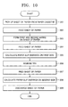
- Figure 10 is a flowchart illustrating a method of measuring and correcting a paper slip distance in a thermal printer according to a third embodiment of the present invention.
- the third embodiment includes the operation of forming the first and second marks M1 and M2 of Figure 6.
- the pickup roller 72 picks up a sheet of heat reactive paper 10 from the paper cassette 70 and moves the sheet of heat reactive paper 10 to the first path (operation 301).
- the sheet of heat reactive paper 10 that enters the first path is supplied to the feeding roller 41 via the paper guide 65.
- the feeding roller 41 feeds the sheet of heat reactive paper 10 back to the second path as illustrated in Figure 8A (operation 302).
- the TPH 51 is separated from the platen roller 55 by a predetermined distance.
- the TPH 51 is lowered to press against the sheet of heat reactive paper 10.
- the sheet of heat reactive paper 10 is fed forward as the feeding roller 41 is rotated in reverse.
- the first and second marks M1 and M2 are formed on the sheet of heat reactive paper 10 (operation 303).
- the distance between the first and second marks M1 and M2 is calculated by the driving distance of the feeding roller and stored as a first distance (D9).
- the first distance (D9) indicates the distance travelled by the sheet of heat reactive paper 10 when the sheet of heat reactive paper 10 is in contact with the TPH 51.
- the sheet of heat reactive paper 10 is fed back so that the first mark M1 on the sheet of heat reactive paper 10 passes through the optical sensor 53 (operation 304).
- the optical sensor 53 sequentially detects the first and second marks M1 and M2 formed on the first side of the sheet of heat reactive paper 10.
- the TPH 51 is kept separated from the heat reactive paper 10 by a predetermined amount.
- the controlling unit 80 calculates a second distance D10 between the first mark M1 and the second mark M2 based on a driving distance of the feeding roller 41.
- the second distance D10 corresponds to the actual distance between the first and second marks M1 and M2.
- the controlling unit 80 compares the second distance D10 with the first distance D9 in operation 303 and, based on the result of the comparison, calculates a paper slip distance (S3) and a paper slip rate (SR3) using Equation 3 (operation 305).
- the sheet of heat reactive paper 10 is fed forward a predetermined distance so that the sheet of heat reactive paper 10 does not interfere with the image forming unit 50 when the image forming unit 50 rotates.
- the paper slip distance (S3) on the first side of the sheet of heat reactive paper 10 is measured.
- Print data input from the external source is successively printed on the print region PR of the first side taking into account the paper slip distance (S3) on the first side of the sheet of heat reactive paper 10.
- An corrected length obtained by multiplying a length of the print data in the printing direction by a correction ratio (D10/D9) is printed.
- the image forming unit 50 is rotated and, accordingly, the position of the TPH 51 is reversed such that the TPH 51 faces the second side of the sheet of heat reactive paper 10 (operation 306).
- the TPH 51 is moved so as to form a gap between the upper platen roller 55 and the TPH 51 such that the sheet of heat reactive paper 10 may be passed through the gap without resistance. Then, the sheet of heat reactive paper 10 is fed back to the second path such that the first mark M1 on the sheet of heat reactive paper 10 passes through the optical sensor 53 (operation 307).
- the TPH 51 is moved to press against the back-fed sheet of heat reactive paper 10. While the feeding roller 41 feeds the sheet of heat reactive paper 10 forward, the distance between the first and second marks M1 and M2 is measured. Then, the paper slip distance and the paper slip rate on the second side of the sheet of heat reactive paper 10 are calculated (operation 308). Since operation 308 is identical to operation 305, a detailed description of operation 308 is omitted.
- the paper slip distance (S3) on the second side of the sheet of heat reactive paper 10 is measured.
- Print data input from an external source is successively printed on the print region PR of the second side taking into account the paper slip distance (S3) on the second side of the sheet of heat reactive paper 10.
- a corrected length obtained by multiplying a length of the print data in the printing direction by a correction ratio (D10/D9) is printed.
- the conveying unit 40 stops moving the sheet of heat reactive paper 10. Instead, the sheet of heat reactive paper 10 is moved and discharged out of the thermal printer by the paper discharge unit 60 (operation 309).
- a thermal printer using heat reactive paper easily measures the paper slip distance of a sheet of heat reactive paper. If a print length in a printing direction is corrected in consideration of the paper slip distance when printing is performed on a corresponding side of the sheet of heat reactive paper, an image with improved quality is obtained.
- this compensation may be carried out when the printer is manufactured or by the end-user.
Landscapes
- Handling Of Sheets (AREA)
- Electronic Switches (AREA)
- Handling Of Cut Paper (AREA)
Abstract
Description
| Printed Side | Actual Distance/Target Distance | Paper Slip Distance (mm) |
| First side | 0.99742 | 3.81 |
| Second side | 0.97501 | 0.39 |
Claims (23)
- A printer kit, comprising a thermal printer having:a print head (51);feeding means (41,42) for feeding a sheet (10) into the printer; andmovement monitoring means for outputting a movement signal indicative of the movement of the roller, characterised bya slip calibration sheet (10) having a first calibration mark (M1) located thereon, wherein the first mark is spaced from a reference (M2) by a predetermined distance (D5), andthe printer comprising:detection means (53) for outputting a detection signal indicative of the detection of the reference (M2) and the first calibration mark (M1) on the slip calibration sheet (10); anda controller for calibrating for the slip in the printer on the basis of the detection signal and the movement signal.
- A printer kit according to claim 1, wherein the reference comprises a second calibration mark (M2).
- A printer kit according to either one of claims 1 or 2, wherein the detection means (53) is operable to detect the first calibration mark (M1) on both the first and second side of the slip calibration sheet.
- A printer kit according to any one of claims 1, 2 or 3 wherein the print head (51) is operable to rotate between the first and second side of the calibration sheet about an axis.
- A method of compensating for paper slip in a thermal printer, comprising the steps of(a) picking up a sheet of print paper on which first and second marks are formed that are separated a predetermined distance from each other in a printing direction and feeding the sheet of print paper to a print path;(b) detecting the first and second marks while feeding the sheet of print paper to the print path and calculating a paper slip distance on a first side of the sheet of print paper facing a thermal printhead;(c) rotating the thermal printhead to face a second side of the sheet of print paper;(d) feeding the sheet of paper to the print path; and(e) detecting the first and second marks while feeding the sheet of print paper to the print path and calculating a paper slip distance on the second side.
- The method of claim 5, further comprising
performing the steps (b) and (e) with at least one optical sensor disposed a predetermined height from the sheet of print paper. - The method of claim 5, further comprising
forming the first and second marks in a print region of the sheet of print paper, a trim region being disposed at a front portion and a print region being disposed in the printing direction. - The method of claim 5, further comprising
forming the first and second marks in a trim region of the sheet of print paper, the trim region being disposed at a front portion and a print region being disposed in the printing direction. - The method of claim 8, wherein
the step (b) further comprises printing print data of the first side in the printing direction in consideration of the paper slip distance on the first side. - The method of claim 9, wherein
the step (e) further comprises printing print data of the second side in the printing direction in consideration of the paper slip distance on the second side. - The method of claim 5, further comprising
forming the first and second marks at a trim region and a print region, respectively, the sheet of print paper having a trim region at a front portion and a print region in the printing direction. - A method of compensating for paper slip in a thermal printer, comprising the steps of(a) picking up a sheet of print paper and feeding the sheet of print paper to a print path;(b) forming first and second marks that are separated a predetermined distance from each other on a first side of the sheet of print paper in a printing direction while feeding the sheet of print paper;(c) detecting the first and second marks while feeding the sheet of print paper to the print path and calculating a paper slip distance on the first side of the sheet of print paper facing a thermal printhead;(d) rotating the thermal printhead to face a second side of the sheet of print paper; and(e) detecting the first and second marks while feeding the sheet of print paper to the print path and calculating a paper slip distance on the second side.
- The method of claim 12, wherein
the steps (b) and (e) further comprise measuring a distance between the first and second marks where a paper slip distance is included. - The method of claim 12, wherein
the step (c) further comprises measuring an actual distance between the first and second marks. - The method of claim 12, further comprising
performing the steps (b) and (e) with at least one optical sensor a predetermined height separated from the sheet of print paper. - The method of claim 12, further comprising
forming the first and second marks in a print region of the sheet of print paper having a trim region at a front portion and the print region in the printing direction. - The method of claim 12, further comprising
forming the first and second marks in a trim region of the sheet of print paper having the trim region at the front portion and a print region in the printing direction. - The method of claim 17, wherein
the step (c) further comprises printing print data of the first side in the printing direction in consideration of the paper slip distance on the first side. - The method of claim 18, wherein
the step (e) further comprises printing print data of the second side in the paper moving direction in consideration of the paper slip distance on the second side. - The method of claim 12, further comprising
forming the first and second marks at the a trim region and a print region, respectively, of the sheet of print paper having the trim region at a front portion and the print region in the printing direction. - A method of compensating for paper slip in a thermal printer, comprising the steps of(a) picking up a sheet of print paper on which first and second marks are formed that are separated a predetermined distance from each other in a printing direction and feeding the sheet of print paper to a print path;(b) detecting the first and second marks while feeding the sheet of print paper to the print path; and(c) calculating a paper slip distance of the sheet of print paper.
- The method of claim 20, further comprising
forming the first and second marks in a trim region of the sheet of print paper having the trim region at a front portion and a print region in the printing direction. - The method of claim 22, wherein
the step (c) further comprises printing print data in the printing direction in consideration of the paper slip distance of the sheet of print paper.
Applications Claiming Priority (2)
| Application Number | Priority Date | Filing Date | Title |
|---|---|---|---|
| KR2004035527 | 2004-05-19 | ||
| KR1020040035527A KR20050110488A (en) | 2004-05-19 | 2004-05-19 | Method of measuring slip of thermal printer |
Publications (2)
| Publication Number | Publication Date |
|---|---|
| EP1598201A2 true EP1598201A2 (en) | 2005-11-23 |
| EP1598201A3 EP1598201A3 (en) | 2006-09-20 |
Family
ID=34939581
Family Applications (1)
| Application Number | Title | Priority Date | Filing Date |
|---|---|---|---|
| EP05103517A Withdrawn EP1598201A3 (en) | 2004-05-19 | 2005-04-28 | A paper position correction method for a printer |
Country Status (4)
| Country | Link |
|---|---|
| US (1) | US20050259141A1 (en) |
| EP (1) | EP1598201A3 (en) |
| KR (1) | KR20050110488A (en) |
| CN (1) | CN1699064A (en) |
Families Citing this family (7)
| Publication number | Priority date | Publication date | Assignee | Title |
|---|---|---|---|---|
| KR100608000B1 (en) * | 2004-08-16 | 2006-08-02 | 삼성전자주식회사 | Thermal image forming apparatus having a cooling fan |
| KR20060058943A (en) * | 2004-11-26 | 2006-06-01 | 삼성전자주식회사 | Image forming apparatus and method |
| CN101670714A (en) * | 2009-09-18 | 2010-03-17 | 陈东 | Printer with specified print media and function of repeatedly using for multiple times |
| CN103171314B (en) * | 2011-12-21 | 2015-06-17 | 北大方正集团有限公司 | Method and device for controlling ink jet printing |
| JP2014208408A (en) * | 2013-04-16 | 2014-11-06 | キヤノン株式会社 | Printing device and printing method |
| WO2019209295A1 (en) * | 2018-04-26 | 2019-10-31 | Hewlett-Packard Development Company, L.P. | Microembossed print media |
| CN113665256B (en) * | 2021-07-29 | 2023-10-03 | 浪潮金融信息技术有限公司 | Intelligent printer and printing method |
Family Cites Families (12)
| Publication number | Priority date | Publication date | Assignee | Title |
|---|---|---|---|---|
| JPS59215880A (en) * | 1983-05-25 | 1984-12-05 | Canon Inc | Recorder |
| US5967394A (en) * | 1994-11-04 | 1999-10-19 | Roll Systems, Inc. | Method and apparatus for pinless feeding of web to a utilization device |
| US6109719A (en) * | 1998-06-03 | 2000-08-29 | Lexmark International, Inc. | Printhead thermal compensation method and apparatus |
| DE19840301A1 (en) * | 1998-09-04 | 2000-03-09 | Colorpartner Gmbh Entwicklung | Printing graphical illustrations on both sides of base material with digital triggering of two individual printing units on smooth printing material like paper or plastics film |
| US6158344A (en) * | 1998-12-03 | 2000-12-12 | Hewlett-Packard Company | Linefeed calibration using an integrated optical sensor |
| US6296405B1 (en) * | 2000-01-04 | 2001-10-02 | International Business Machines Corporation | Duplex check printer using a print mechanism pivoted between document paths |
| US6364549B1 (en) * | 2000-04-27 | 2002-04-02 | Hewlett-Packard Company | Calibration of a media advanced system |
| JP2001310503A (en) * | 2000-04-28 | 2001-11-06 | Canon Inc | Recording device |
| US6373042B1 (en) * | 2000-08-29 | 2002-04-16 | Xerox Corporation | Registration system for a digital printer which prints multiple images on a sheet |
| JP3684159B2 (en) * | 2001-01-31 | 2005-08-17 | キヤノン株式会社 | Recording apparatus and recording method |
| US6490421B2 (en) * | 2001-02-12 | 2002-12-03 | Hewlett-Packard Company | Methods and apparatus for correcting rotational skew in duplex images |
| JP4507509B2 (en) * | 2002-10-18 | 2010-07-21 | コニカミノルタホールディングス株式会社 | Inkjet recording device |
-
2004
- 2004-05-19 KR KR1020040035527A patent/KR20050110488A/en not_active Ceased
-
2005
- 2005-04-19 US US11/108,829 patent/US20050259141A1/en not_active Abandoned
- 2005-04-28 EP EP05103517A patent/EP1598201A3/en not_active Withdrawn
- 2005-05-18 CN CNA2005100729493A patent/CN1699064A/en active Pending
Also Published As
| Publication number | Publication date |
|---|---|
| KR20050110488A (en) | 2005-11-23 |
| US20050259141A1 (en) | 2005-11-24 |
| EP1598201A3 (en) | 2006-09-20 |
| CN1699064A (en) | 2005-11-23 |
Similar Documents
| Publication | Publication Date | Title |
|---|---|---|
| KR100636135B1 (en) | Image Alignment Printing Method of Duplexer | |
| US7417657B2 (en) | Thermal printer and printing method | |
| US7528852B2 (en) | Method of differentiating types of heat sensitive paper | |
| JP2017159654A (en) | Paper sheet printer with sensor system, method for calibrating sensor system, and method for adjusting sensor system | |
| EP1598201A2 (en) | A paper position correction method for a printer | |
| US6407678B1 (en) | Belt media drive for printer with dual belt encoders | |
| JP2011121271A (en) | Recording method | |
| JP2011067991A (en) | Image recording device and method of adjusting ejection timing | |
| US7333122B2 (en) | Method of printing thermal media by aligning image | |
| KR100580263B1 (en) | Printing method of thermal reaction paper | |
| KR100601691B1 (en) | Image alignment printing method of thermal reaction paper | |
| US20060012665A1 (en) | Print media and photo printer | |
| KR100644619B1 (en) | Printing method according to vertical resolution | |
| JP2007216480A (en) | Recording apparatus control method and recording apparatus | |
| JP2004091112A (en) | Discrimination device, printing device, program, and computer system | |
| JP2008080676A (en) | Discrimination method of ink ribbon and thermal transfer printer | |
| JP4492147B2 (en) | Ink jet recording apparatus and recording medium movement control method | |
| JP2004202824A (en) | Recording apparatus and temperature measuring method thereof | |
| JPH0671992A (en) | Color printer | |
| JP2001019213A (en) | Paper feeder of printer |
Legal Events
| Date | Code | Title | Description |
|---|---|---|---|
| PUAI | Public reference made under article 153(3) epc to a published international application that has entered the european phase |
Free format text: ORIGINAL CODE: 0009012 |
|
| AK | Designated contracting states |
Kind code of ref document: A2 Designated state(s): AT BE BG CH CY CZ DE DK EE ES FI FR GB GR HU IE IS IT LI LT LU MC NL PL PT RO SE SI SK TR |
|
| AX | Request for extension of the european patent |
Extension state: AL BA HR LV MK YU |
|
| RIC1 | Information provided on ipc code assigned before grant |
Ipc: B41J 13/03 20060101ALI20060531BHEP Ipc: B41J 13/00 20060101ALI20060531BHEP Ipc: B41J 11/00 20060101ALI20060531BHEP Ipc: B41J 3/60 20060101ALI20060531BHEP Ipc: B41J 2/32 20060101ALI20060531BHEP Ipc: B41J 11/46 20060101ALI20060531BHEP Ipc: B41J 11/44 20060101AFI20060531BHEP |
|
| PUAL | Search report despatched |
Free format text: ORIGINAL CODE: 0009013 |
|
| AK | Designated contracting states |
Kind code of ref document: A3 Designated state(s): AT BE BG CH CY CZ DE DK EE ES FI FR GB GR HU IE IS IT LI LT LU MC NL PL PT RO SE SI SK TR |
|
| AX | Request for extension of the european patent |
Extension state: AL BA HR LV MK YU |
|
| AKX | Designation fees paid | ||
| REG | Reference to a national code |
Ref country code: DE Ref legal event code: 8566 |
|
| STAA | Information on the status of an ep patent application or granted ep patent |
Free format text: STATUS: THE APPLICATION IS DEEMED TO BE WITHDRAWN |
|
| 18D | Application deemed to be withdrawn |
Effective date: 20070321 |