EP1598152A1 - Industrial robot - Google Patents
Industrial robot Download PDFInfo
- Publication number
- EP1598152A1 EP1598152A1 EP04818360A EP04818360A EP1598152A1 EP 1598152 A1 EP1598152 A1 EP 1598152A1 EP 04818360 A EP04818360 A EP 04818360A EP 04818360 A EP04818360 A EP 04818360A EP 1598152 A1 EP1598152 A1 EP 1598152A1
- Authority
- EP
- European Patent Office
- Prior art keywords
- teaching device
- subsidiary
- industrial robot
- primary
- production line
- Prior art date
- Legal status (The legal status is an assumption and is not a legal conclusion. Google has not performed a legal analysis and makes no representation as to the accuracy of the status listed.)
- Granted
Links
Images








Classifications
-
- B—PERFORMING OPERATIONS; TRANSPORTING
- B25—HAND TOOLS; PORTABLE POWER-DRIVEN TOOLS; MANIPULATORS
- B25J—MANIPULATORS; CHAMBERS PROVIDED WITH MANIPULATION DEVICES
- B25J13/00—Controls for manipulators
- B25J13/06—Control stands, e.g. consoles, switchboards
-
- B—PERFORMING OPERATIONS; TRANSPORTING
- B25—HAND TOOLS; PORTABLE POWER-DRIVEN TOOLS; MANIPULATORS
- B25J—MANIPULATORS; CHAMBERS PROVIDED WITH MANIPULATION DEVICES
- B25J19/00—Accessories fitted to manipulators, e.g. for monitoring, for viewing; Safety devices combined with or specially adapted for use in connection with manipulators
- B25J19/06—Safety devices
Definitions
- the present invention relates to an industrial robot having a function of restricting the operation conducted by a worker.
- the industrial robot In the conventional industrial robot, the following problems may be encountered.
- the industrial robot When the robot is operated by a worker while a task is being allotted to the worker, in the case where a function of the industrial robot, which is exclusively to be executed by a supervisor, is mistakenly executed by the worker, the setting of the robot operation is changed without letting the supervisor know the change. Therefore, problems are unexpectedly caused in the circumstances.
- some industrial robots are provided with a security function.
- the industrial robots include: a name inputting means for inputting the name of a worker; and a discrimination means for discriminating the inputted name, wherein the operation capable of being conducted by the worker is restricted by the result of the discrimination.
- this technique is disclosed in the official gazette of JP-A-2002-239953.
- the industrial robots include: a sill level judging means for judging a content of the operation executed by a worker; and a changing means for changing a message for supporting the operation and a content of the operating image plane according to the result of the judgment.
- a sill level judging means for judging a content of the operation executed by a worker
- a changing means for changing a message for supporting the operation and a content of the operating image plane according to the result of the judgment.
- a robot controller teaching system including: a programming device operated by a personal computer for general purpose; and a simple teaching device composed of a small number of switches.
- a programming device operated by a personal computer for general purpose and a simple teaching device composed of a small number of switches.
- this technique is disclosed in the official gazette of JP-A-6-250729.
- Fig. 18 is a view showing an arrangement of the conventional industrial robot.
- Reference numeral 1801 is a manipulator
- reference numeral 1809 is a tool such as a welding torch or a hand opening and closing device which is attached to the manipulator 1801 according to the purpose of the use of the industrial robot
- reference numeral 1802 is a robot control unit for controlling the manipulator
- reference numeral 1808 is a teaching device for operating the manipulator and the robot control unit
- reference numeral 1803 is CPU for controlling the robot control unit itself
- reference numeral 1804 is a corresponding section for conducting correspondence with the teaching device
- reference numeral 1805 is ROM which is a read-only memory exclusively used for accommodating and reading a program which is interpreted by CPU so that CPU can be operated
- reference numeral 1806 is RAM which is a random access memory for writing and reading an operation program and operation environment setting data taught by the worker
- reference numeral 1807 is a drive section for driving the manipulator.
- Patent Document 1 Official gazette of JP-A-2002-239953
- Patent Document 2 Official gazette of Japanese Patent No. 2796160
- Patent Document 3 Official gazette of JP-A-6-250729
- a supervisor can determine the operation, which is capable of being conducted by a worker belonging to a production line, with a primary teaching device.
- the present invention realizes an industrial robot including a primary teaching device, a subsidiary teaching device and also including a function of restricting the operation capable of being conducted by the subsidiary teaching device. Due to the foregoing, when the production line worker uses only the subsidiary teaching device, it is possible to prevent the production line worker from executing a function of the industrial robot which is originally to be executed only by the supervisor.
- Fig. 1 is a view showing an arrangement of the industrial robot to realize the present invention.
- the reference numeral 101 is a manipulator
- reference numeral 102 is a robot control unit for controlling the manipulator
- reference numeral 103 is CPU for controlling the robot control unit itself
- reference numeral 104 is a corresponding section for conducting correspondence with a teaching device
- reference numeral 105 is ROM exclusively used for accommodating and reading out a program to be interpreted by CPU so that CPU can be operated
- reference numeral 106 is RAM capable of accommodating, writing and reading an operation program, which has been taught by a worker, and data for setting the operation environment
- reference numeral 107 is a drive section for driving the manipulator
- reference numeral 108 is a primary teaching device provided for controlling the manipulator 101 through the robot control unit 102
- reference numeral 109 is a subsidiary teaching device provided for controlling the manipulator 101 through the robot control unit 102 in the same manner as that of the primary teaching device 108.
- the primary teaching device is prepared as a teaching device with which a supervisor conducts operation
- the subsidiary teaching device is prepared as a teaching device with which a production worker conducts operation.
- the supervisor assumes a role of newly making a teaching program with the primary teaching device 108.
- the production line worker assumes a role of correcting a teaching program of the industrial robot which is in operation in the production line.
- a specific example of the primary teaching device 108 is shown by reference numeral 201 in Fig. 2.
- a large number of operation keys are arranged so that the supervisor can conduct a large number of types of work permitted only to the supervisor.
- the liquid crystal image plane 202 mounted on the primary teaching device 108 is highly fine.
- the subsidiary teaching device 301 includes a necessary minimum number of operation keys so that the production line worker can easily correct a teaching program in the industrial robot which is in operation.
- the liquid crystal image plane mounted on the subsidiary teaching device 109 has a necessary minimum indication capacity.
- the change in the teaching point indicates a change in the tip end position of the tool 110, which is attached to the end portion of the manipulator 101, and a change in the teaching point accompanied by a change in the tool posture.
- the supervisor controls the manipulator 101 by operating the robot control unit 102 with the primary teaching unit 108. Specifically, an operation command sent from the primary teaching device 108 is transmitted to CPU 103 through the corresponding section 104, and CPU 103 executes a control program to control the drive section 107, so that the manipulator 101 can act by the action of the drive section 107.
- the supervisor operates the manipulator 101 to an objective position and posture and conducts the operation to register a teaching point for each position and posture with the primary teaching device 108. For example, when the manipulator 101 is operated and the registration is made by the primary teaching device for each teaching point previously determined, the position and posture of the manipulator 101 are registered in RAM 106 as the coordinates information of three dimension. Due to the foregoing, the position and posture of the manipulator 101 are stored in RAM 106. Therefore, when this operation is successively conducted for each position to be registered as a teaching point, the operation program can be made.
- the supervisor selects and executes an objective program with the primary teaching device 108 and starts the operation.
- CPU 103 interprets the operation program and gives a command of operating the manipulator 101 to the drive section, and then the work can be executed when the manipulator 101 passes through the teaching points previously registered.
- the production line worker corrects a teaching program of the industrial robot, which is in operation in the production line, as follows.
- CPU 103 interprets the command of stoppage given by the production worker, so that the manipulator 101 can be stopped.
- the production line worker operates the manipulator 101 to an objective position and posture with the subsidiary teaching device so as to correct the teaching point. Due to the foregoing, the position and posture of the manipulator 101 can be overwritten and stored in RAM 106 as the coordinates information. When this operation is successively conducted, the operation program can be corrected.
- the production line worker continuously operates the operation program and makes the industrial robot conduct welding or handling, in the same manner as that of using the primary teaching device 108 described before, the production line worker selects an objective operation program with the subsidiary teaching device 109 and starts operation. Due to the foregoing, CPU 103 interprets the operation program and continuously controls the manipulator 101.
- the embodiment when the embodiment is provided with a function of restricting the operation capable of being conducted by the subsidiary teaching device and the production line worker uses only the subsidiary teaching device, the production line worker can be prevented from executing the industrial robot function which is originally to be executed by the supervisor.
- the restriction of the operation, which can be conducted by the subsidiary teaching device in the present embodiment will be described in detail later, which is the same in the cases of Embodiments 2 to 4.
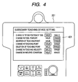
- the supervisor calls a setting image plane to restrict the operation, which can be conducted by the subsidiary teaching device, with the primary teaching device 108. Then, the subsidiary teaching device setting image plane 401 shown in Fig. 4 is displayed on the liquid crystal image plane. The supervisor sets the function of permitting the operation conducted by the subsidiary teaching device on the subsidiary teaching device setting image plane 401 in validity and also sets the operation, which is not permitted to conduct by the subsidiary teaching device, in invalidity.
- the supervisor conducts setting with the primary teaching device 108 as follows.
- the tool tip end position change is valid, the tool posture change is invalid, the teaching point addition is invalid, the teaching point change is valid, the deletion of the teaching point is invalid, the teaching point velocity change is valid, and the welding condition change is valid.
- the teaching point change operation itself is permitted, however, the tool posture change is not permitted.
- the production line worker operates the industrial robot with the subsidiary teaching device 109 and changes the tool posture and then changes the teaching point.
- the warning indication 501 of Fig. 5 the indication that the operation is not permitted is displayed, and the teaching point change operation accompanied by a tool posture change can not be executed.
- the teaching point change operation itself is permitted and the production line worker operates the industrial robot with the subsidiary teaching device 109 under the condition that the tool tip end position change is permitted so that the tool tip end position ca be changed and then the production line worker conducts the teaching point change operation, as shown by the completion indication 601 in Fig. 6, the indication that the processing has been completed is displayed. Therefore, the teaching point change operation accompanied by the tool tip end position change is executed.
- the supervisor conducts setting with the primary teaching device 108 as follows.
- the tool tip end position change is valid, the tool posture change is invalid, the teaching point addition is invalid, the teaching point change is valid, the deletion of the teaching point is invalid, the teaching point velocity change is valid, and the welding condition change is valid.
- the warning indication 501 is displayed, and the processing can not be executed.
- the completion indication 601 is displayed and the processing can be executed.
- the completion indication 601 is displayed and the processing can be executed.
- the completion indication 601 is displayed and the processing can be executed.
- this embodiment is provided with the function of restricting the operation capable of being conducted by the subsidiary teaching device, and the production line worker uses only the subsidiary teaching device. Due to the foregoing, the production line worker can be prevented from executing the function of the industrial robot which is originally to be executed by the supervisor.
- the items, which can be set by the supervisor with the primary teaching device 108 to be valid or invalid on the subsidiary teaching device setting image plane 401 shown in Fig. 4 are the change in the tool tip end position, the change in the tool posture, the addition of the teaching point, the deletion of the teaching point, the change in the teaching point velocity, and the change in the welding condition.
- the function of setting to be valid or invalid on the subsidiary teaching device setting image plane 401 is not particularly limited.
- the change in the output state, the change in the waiting time and the change of ON/OFF of the hand opening and closing device may be set on the subsidiary teaching device setting image plane 401.
- the user level 3 represents the highest level.
- the function which is set at the user level 3 on the subsidiary teaching device setting image plane 701, can be operated only by a person of the user level 3. For example, a supervisor in charge of the production line operates this function.
- the user level 2 represents the intermediate level.
- the function which is set at the user level 2 on the subsidiary teaching device setting image plane 701, can be operated only by persons of the user levels 2 and 3. For example, a programmer permitted to add and delete the teaching points corresponds to the person of the user level 2.
- the user level 1 represents the lowest level.
- the function which is set at the user level 1 on the subsidiary teaching device setting image plane 701, can be operated only by persons of the user levels 1, 2 and 3. For example, a production line worker permitted to change the teaching points corresponds to the person of the user level 1.
- the supervisor conducts setting as follows with the primary teaching device 108 as shown in the subsidiary teaching device setting image plane 701 of Fig. 7.
- the change in the tool tip end position is the user level 1
- the change in the tool posture is the user level 1
- the addition of the teaching point is the user level 2
- the change in the teaching point is the user level 1
- the deletion of the teaching point is the user level 2
- the change in the teaching point velocity is the user level 3
- the change in the welding condition is the user level 3.
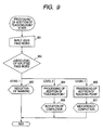
- Fig. 9 shows a case of processing in which the production line worker of the user level 1 operates an industrial robot with the subsidiary teaching device 109 and conducts the operation of adding the teaching point. Since the production line worker is the user level 1, the operation of adding the teaching point is not permitted according to the subsidiary teaching device setting image plane 701 shown in Fig. 7 which has been set by the supervisor with the primary teaching device 108.
- the user level pass word input demanding image plane 801 is displayed as shown in Fig. 8.
- the production line worker inputs a user level pass word which is given by the supervisor.
- the processing flow 902 of Fig. 9 the level of the inputted pass word is judged.
- the pass word inputted on the image plane 801 is transmitted to CPU 103 via the corresponding section 104, and CPU 103 judges the level of the inputted pass word according to the processing flow 902 shown in Fig. 9. As a result of the judgment, an indication of warning is transmitted to the subsidiary teaching device 109 via the corresponding section 104. In the other embodiments, the same judgment processing is conducted.
- the production line worker Since the production line worker is the user level 1, the user level pass word inputted by the production line worker is judged to be the user level 1, and the process proceeds to the processing flow 903 and the warning indication 501 of Fig. 5 is displayed and further an indication that the operation is not permitted is displayed. It is impossible for the production line worker to add the teaching point which has been set so that the addition can not be executed in the subsidiary teaching device 109.
- the user level pass word input demanding image plane 801 is displayed as shown in Fig. 8.
- the user level pass word which is given from the supervisor to the programmer, is inputted onto the image plane 801.
- the processing flow 902 shown in Fig. 9 the level judgment processing to judge the thus inputted pass word is executed according to the processing flow 902 shown in Fig. 9. Since the programmer is the user level 2, the user level pass word inputted by the programmer is judged to be the user level 2, and the process proceeds to the processing flow 904 and the completion indication 601 of Fig. 6 is displayed. In this way, the indication that the processing has been completed is displayed, and the operation of adding the teaching point is executed.
- Fig. 9 the processing is shown in Fig. 9 in which the supervisor of the level 3 in charge of the production line operates the industrial robot with the subsidiary teaching device 109 and conducts the operation of adding the teaching point. Since the supervisor is the user level 3, according to the subsidiary teaching device setting image plane 701 shown in Fig. 7 which has been set by the supervisor with the primary teaching device 108, the teaching point adding operation is permitted.
- the supervisor conducts the teaching point adding operation with the subsidiary teaching device 109, according to the processing flow 901 shown in Fig. 9, the user level pass word input demanding image plane 801 is displayed as shown in Fig. 8. The supervisor inputs the user level pass word of the supervisor himself onto this image plane 801.
- the processing flow 902 shown in Fig. 9 the level judgment processing of the inputted pass word is conducted. Since the supervisor is the user level 3, the user level pass word inputted by the supervisor is judged to be the user level 3, and the process proceeds to the processing flow 905 and the completion indication of Fig. 6 is displayed. In this way, the indication that the processing has been completed is displayed, and the operation of adding the teaching point is executed.
- the operation capable of being conducted by the subsidiary teaching device is classified by the primary teaching device as the user level, and the subsidiary teaching device is made to have the user level judging function. Due to the above constitution, when the production line worker or the programmer operates the subsidiary teaching device and inputs the user level of himself, the contents capable of being operated are restricted. Therefore, a plurality of levels can be provided in the operation which can be conducted by the production line worker and the programmer.
- the items, which can be set by the supervisor with the primary teaching device 108 to be valid or invalid on the subsidiary teaching device setting image plane 701 in Fig. 7, are the change in the tool tip end position, the change in the tool posture, the addition of the teaching point, the deletion of the teaching point, the change in the teaching point velocity, and the change in the welding condition.
- the function of setting to be valid or invalid on the subsidiary teaching device setting image plane 701 is not particularly limited.
- the change in the output state, the change in the waiting time and the change of ON/OFF of the hand opening and closing device may be set on the subsidiary teaching device setting image plane 401.
- FIGs. 10 and 11 are views showing an arrangement of the industrial robot to realize the present invention.
- Reference numeral 1001 is a connecting section for connecting the primary teaching device 108 or the subsidiary teaching device 109 to the robot control unit 102. As long as this connecting section 1001 can be connected to the primary teaching device 108 and the subsidiary teaching device 109, the shape of this connecting section 1001 is not particularly limited to a specific one.
- the supervisor uses the primary teaching device 108, only the primary teaching device 108 is connected to the connecting section 1001 as shown in Fig. 10.
- the supervisor makes an operation program with the primary teaching device 108, the operation program is selected and the starting operation is conducted and the operation capable of being conducted by the subsidiary teaching device is restricted.
- the supervisor detaches the primary teaching device 108 from the connecting section 1001 and attaches only the subsidiary teaching device 109 to the connecting section 1001 as shown in Fig. 11.
- the production line worker corrects the teaching program of an industrial robot, which is being operated now, with the subsidiary teaching device 109 and also in the case where the production line worker continuously runs the operation program and makes the industrial robot conduct the welding or handling work, the production line worker selects the objective operation program with the subsidiary teaching device 109 and conducts the starting operation in the same manner as that of Embodiments 1 and 2.
- the supervisor detaches the primary teaching device and replaces it with the subsidiary teaching device. Due to the foregoing, the production line worker can use only the subsidiary teaching device. Therefore, it becomes possible to prevent the production line worker from executing the industrial robot function which is originally to be executed by the supervisor.
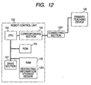
- Fig. 12 is a view showing an arrangement of the industrial robot to realize the present invention.
- Reference numeral 1201 is a storage device for storing the information to restrict the operation.
- a portion of RAM which is a memory for accommodating, writing and reading the operation program and the operation environment setting program taught by the worker, is used as a restricting information storing region.
- the supervisor calls the subsidiary teaching device setting image plane 401 to restrict the operation, which can be conducted by the subsidiary teaching device 109, with the primary teaching device 108 and conducts the setting of the function of restricting the operation when the production line worker operates the subsidiary teaching device. Then, the information indicating whether the respective operation is valid or invalid is automatically stored in the restricting information storage region 1201 via the connecting section 1001, the corresponding section 104 and CPU 103. Alternatively, the information indicating whether the respective operation is valid or invalid is stored in the restricting information storage region 1201 via the connecting section 1001, the corresponding section 104 and CPU 103 when the operation button of the primary teaching device 108 is pressed. Concerning the way of storing the information whether it is valid or invalid may be stored for the respective operation. Alternatively, the valid operation area and the invalid operation area, which is restricted, may be made, and the operation fitted to the respective area may be stored.
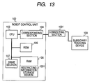
- the supervisor detaches the primary teaching device 108 from the connecting section 1001 and attaches only the subsidiary teaching device 109 to the connecting section 1001 as shown in Fig. 13.
- the supervisor conducts setting as follows.
- the change in tool tip end position is valid, the change in the tool posture is invalid, the change in the teaching point addition is invalid, the change in the teaching point is valid, the deletion of the teaching point is invalid, the change in the teaching point velocity is valid, and the change in the welding condition is valid.
- the above pieces of information are stored in the restricting information storing region 1201. In this case, although the operation of changing the teaching point is permitted, the change in the tool posture is not permitted.
- the subsidiary teaching device 109 displays an indication that the operation is not permitted as shown by the warning display 501 in Fig. 5.
- CPU 103 programming is made so that a command can not be given to the manipulator 101 with respect to the operation which is stored in the restricting information storing region 1201 to be invalid. Accordingly, the operation of changing the teaching point, which is accompanied by the change in the tool posture, can not be executed.
- the industrial robot includes a function of restricting the operation capable of being conducted by the subsidiary teaching device. Therefore, the production line worker uses only the subsidiary teaching device. Accordingly, it is possible to prevent the production line worker from executing the industrial robot function which is originally to be executed by the supervisor.
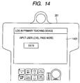
- the supervisor operates the primary teaching device 201 in order to conduct the operation, which is permitted only for the supervisor, such as the operation of making an operation program or restricting the operation capable of being conducted by the subsidiary teaching device, first, the user level pass word input demanding image plane 1401 shown in Fig. 14 is displayed on a liquid crystal image plane.
- the user level 3 represents the highest level.
- the supervisor corresponds to the user level 3 who is in charge of the production line and capable of operating all functions of the industrial robot.
- the user level 2 represents the intermediate level.
- the programmer corresponds to the user level 2 who is permitted only to teach the operation program and not permitted to conduct the operation to restrict the operation capable of being conducted by the subsidiary teaching device.
- the user level 1 represents the lowest level.
- the production line worker corresponds to the user level 1 who is permitted only to change the teaching points and not permitted to conduct the operation of teaching the operation program or restricting the operation capable of being conducted by the subsidiary teaching device.
- the supervisor of the user level 3 in charge of the production line operates the primary teaching device 201 in order to conduct the operation, which is permitted only for the supervisor, such as the operation of making the operation program or restricting the operation capable of being conducted by the subsidiary teaching device
- the user level pass word input demanding image plane 1401 is displayed as shown in Fig. 14.
- the user pass word of the supervisor himself is inputted.
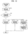
- the level of the thus inputted pass word is judged. Since the supervisor is the user level 3, the user level pass word inputted by the supervisor is judged to be the user level 3.
- the process proceeds to the processing flow 1505, and the operation permitting indication 1601 shown in Fig. 16 is displayed, that is, the indication to permit the operation is displayed.
- the process proceeds to the processing flow 1506, and the operation program is actually made and the permission processing of permitting the operation to restrict the operation capable of being conducted by the subsidiary teaching device is executed.
- the user level pass word input demanding image plane 1401 is displayed as shown in Fig. 14.
- the user level pass word of the production line worker himself is inputted.
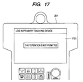
- the level of the thus inputted pass word is executed. Since the production line worker is the user level 1, the user level pass word inputted by the production line worker is judged to be the user level 1. Then, the process proceeds to the processing flow 1503 and the warning indication 1701 shown in Fig.
- the primary teaching device and the secondary teaching device are simultaneously connected to the robot control unit and the primary teaching device is provided with a user judging function, it is impossible for the production line worker to use the primary teaching device, that is, the production line worker can use only the subsidiary teaching device. Accordingly, it is possible to prevent the production line worker from executing the function of an industrial robot which is originally to be executed by the supervisor.
- the present invention can realize an industrial robot including a primary teaching device and a subsidiary teaching device and also including a function to restrict the operation capable of being conducted by the subsidiary teaching device. Therefore, when the production line worker uses only the subsidiary device, it is possible to prevent the production line worker from executing the function of the industrial robot which is originally to be executed by the supervisor. Accordingly, the industrial robot of the present invention is useful for the industry as an industrial robot having the function of restricting the operation of the worker.
Landscapes
- Engineering & Computer Science (AREA)
- Robotics (AREA)
- Mechanical Engineering (AREA)
- Numerical Control (AREA)
- Manipulator (AREA)
- Forklifts And Lifting Vehicles (AREA)
Abstract
Description
Patent Document 1: Official gazette of JP-A-2002-239953
Patent Document 2: Official gazette of Japanese Patent No. 2796160
Patent Document 3: Official gazette of JP-A-6-250729
Claims (6)
- An industrial robot comprising:wherein operation capable of being conducted by the subsidiary teaching device is restricted as compared with operation capable of being conducted by the primary teaching device.a manipulator having a tool at a tip end;a robot control unit for controlling the manipulator; anda primary teaching device and a subsidiary teaching device each for controlling the manipulator through the robot control unit,
- An industrial robot according to claim 1, wherein operation capable of being conducted by the subsidiary teaching device is determined by the primary teaching device.
- An industrial robot according to claim 2, wherein operation capable of being conducted by the subsidiary teaching device is classified as a user level by the primary teaching device, and the subsidiary teaching device includes a user level judging function.
- An industrial robot according to claim 1 or 2, wherein the primary teaching device and subsidiary teaching device are detachably attached to the robot control unit, and either the primary teaching device or the subsidiary teaching device is connected to the robot control unit.
- An industrial robot according to claim 4, wherein the robot control unit includes a storage device for storing information to restrict operation when the primary teaching device or the subsidiary teaching device is connected to the robot control unit.
- An industrial robot according to claim 1, wherein the primary teaching device and subsidiary teaching device are simultaneously connected to the robot control unit, and the primary teaching device includes a user judging function.
Applications Claiming Priority (3)
| Application Number | Priority Date | Filing Date | Title |
|---|---|---|---|
| JP2004002728A JP4325407B2 (en) | 2004-01-08 | 2004-01-08 | Industrial robot |
| JP2004002728 | 2004-01-08 | ||
| PCT/JP2004/016411 WO2005065894A1 (en) | 2004-01-08 | 2004-11-05 | Industrial robot |
Publications (3)
| Publication Number | Publication Date |
|---|---|
| EP1598152A1 true EP1598152A1 (en) | 2005-11-23 |
| EP1598152A4 EP1598152A4 (en) | 2007-11-14 |
| EP1598152B1 EP1598152B1 (en) | 2010-01-13 |
Family
ID=34747056
Family Applications (1)
| Application Number | Title | Priority Date | Filing Date |
|---|---|---|---|
| EP04818360A Expired - Lifetime EP1598152B1 (en) | 2004-01-08 | 2004-11-05 | Industrial robot |
Country Status (7)
| Country | Link |
|---|---|
| US (1) | US7627396B2 (en) |
| EP (1) | EP1598152B1 (en) |
| JP (1) | JP4325407B2 (en) |
| CN (1) | CN100393485C (en) |
| AT (1) | ATE454959T1 (en) |
| DE (1) | DE602004025088D1 (en) |
| WO (1) | WO2005065894A1 (en) |
Cited By (2)
| Publication number | Priority date | Publication date | Assignee | Title |
|---|---|---|---|---|
| EP1782928A1 (en) * | 2005-11-08 | 2007-05-09 | Asea Brown Boveri Ab | An industrial robot system with more than one TPU |
| WO2007054435A1 (en) * | 2005-11-08 | 2007-05-18 | Abb Ab | An industrial robot system with more than one tpu |
Families Citing this family (22)
| Publication number | Priority date | Publication date | Assignee | Title |
|---|---|---|---|---|
| JP5492512B2 (en) * | 2009-09-29 | 2014-05-14 | 株式会社ダイヘン | Animal body monitoring device |
| US9552056B1 (en) | 2011-08-27 | 2017-01-24 | Fellow Robots, Inc. | Gesture enabled telepresence robot and system |
| US9191237B1 (en) * | 2012-05-24 | 2015-11-17 | Dan Barry, Inc. | Wireless communication systems and methods |
| JP5549716B2 (en) * | 2012-08-31 | 2014-07-16 | 株式会社安川電機 | Robot system and teaching method |
| WO2014049871A1 (en) * | 2012-09-28 | 2014-04-03 | 富士機械製造株式会社 | Information display system |
| WO2014126112A1 (en) * | 2013-02-13 | 2014-08-21 | 日本電産サンキョー株式会社 | Industrial robot and industrial robot control method |
| JP5952330B2 (en) | 2014-03-27 | 2016-07-13 | ファナック株式会社 | Machining application robot system with machining condition management function |
| US10373116B2 (en) | 2014-10-24 | 2019-08-06 | Fellow, Inc. | Intelligent inventory management and related systems and methods |
| US10311400B2 (en) | 2014-10-24 | 2019-06-04 | Fellow, Inc. | Intelligent service robot and related systems and methods |
| US9796093B2 (en) | 2014-10-24 | 2017-10-24 | Fellow, Inc. | Customer service robot and related systems and methods |
| CN104552300B (en) * | 2014-12-26 | 2016-02-03 | 佛山市新鹏机器人技术有限公司 | A kind of off-line programing teaching apparatus based on teaching robot and method |
| CN104808484A (en) * | 2015-01-20 | 2015-07-29 | 上海优爱宝机器人技术有限公司 | Robot adaptive control method |
| CN108349089A (en) * | 2015-09-11 | 2018-07-31 | 生活机器人学股份有限公司 | Robot device |
| KR101661313B1 (en) * | 2015-09-15 | 2016-10-04 | (주)피엔에스 | Method for controlling danger facility and computer program for executing the method |
| CN108025439B (en) * | 2015-10-14 | 2021-04-27 | 川崎重工业株式会社 | Robot teaching method and robot arm control device |
| CN106078751A (en) * | 2016-07-27 | 2016-11-09 | 重庆峰创科技有限公司 | A kind of intelligent controlling device of industrial robot |
| JP6816600B2 (en) * | 2017-03-27 | 2021-01-20 | 村田機械株式会社 | Machine tool control device, machine tool control method, and machine tool control program |
| JP7095262B2 (en) * | 2017-11-10 | 2022-07-05 | 株式会社安川電機 | Programming support device, robot system and program generation method |
| US10586082B1 (en) | 2019-05-29 | 2020-03-10 | Fellow, Inc. | Advanced micro-location of RFID tags in spatial environments |
| JP7424028B2 (en) * | 2019-12-16 | 2024-01-30 | 株式会社デンソーウェーブ | robot operation terminal |
| JP7619037B2 (en) * | 2020-12-21 | 2025-01-22 | セイコーエプソン株式会社 | PROGRAM CREATION SUPPORT METHOD, PROGRAM CREATION SUPPORT DEVICE, PROGRAM CREATION SUPPORT PROGRAM, AND STORAGE MEDIUM |
| CN119610057B (en) * | 2024-12-12 | 2025-10-28 | 节卡机器人股份有限公司 | Teaching device and robot welding method |
Family Cites Families (18)
| Publication number | Priority date | Publication date | Assignee | Title |
|---|---|---|---|---|
| JPS58129503A (en) * | 1982-01-27 | 1983-08-02 | Shinko Electric Co Ltd | Teaching device of numerical control robot |
| FI83175C (en) * | 1989-09-12 | 1991-06-10 | Aitec Oy | Procedure for path control of a robotic cell |
| JP2796169B2 (en) | 1990-03-23 | 1998-09-10 | 株式会社タカトリハイテック | Wafer transfer equipment |
| JP2992962B2 (en) * | 1990-03-31 | 1999-12-20 | マツダ株式会社 | Robot teaching device by computer simulation |
| JP2719460B2 (en) | 1991-07-09 | 1998-02-25 | ファナック株式会社 | Teaching operation panel connection device |
| JPH06250729A (en) | 1993-02-23 | 1994-09-09 | Matsushita Electric Ind Co Ltd | Multiple robot controller teaching system |
| JPH0720924A (en) * | 1993-07-07 | 1995-01-24 | Matsushita Electric Ind Co Ltd | Equipment operation management device |
| JP3132463B2 (en) * | 1998-04-07 | 2001-02-05 | 松下電器産業株式会社 | Robot controller |
| JP2000066706A (en) * | 1998-08-21 | 2000-03-03 | Matsushita Electric Ind Co Ltd | Robot control device and control method thereof |
| JP4354608B2 (en) | 2000-05-12 | 2009-10-28 | 株式会社ダイヘン | Teaching method and apparatus for welding robot |
| JP2002239953A (en) | 2001-02-13 | 2002-08-28 | Matsushita Electric Ind Co Ltd | Industrial robot |
| JP3673725B2 (en) * | 2001-04-05 | 2005-07-20 | ファナック株式会社 | Information processing system for robots |
| JP2003311665A (en) * | 2002-04-17 | 2003-11-05 | Yaskawa Electric Corp | Robot system and control device |
| NO317898B1 (en) * | 2002-05-24 | 2004-12-27 | Abb Research Ltd | Procedure and system for programming an industrial robot |
| JP3990262B2 (en) * | 2002-12-02 | 2007-10-10 | ファナック株式会社 | Industrial robot |
| JP3950805B2 (en) * | 2003-02-27 | 2007-08-01 | ファナック株式会社 | Teaching position correction device |
| JP3708083B2 (en) * | 2003-02-28 | 2005-10-19 | ファナック株式会社 | Robot teaching device |
| US6804580B1 (en) * | 2003-04-03 | 2004-10-12 | Kuka Roboter Gmbh | Method and control system for controlling a plurality of robots |
-
2004
- 2004-01-08 JP JP2004002728A patent/JP4325407B2/en not_active Expired - Fee Related
- 2004-11-05 WO PCT/JP2004/016411 patent/WO2005065894A1/en not_active Ceased
- 2004-11-05 EP EP04818360A patent/EP1598152B1/en not_active Expired - Lifetime
- 2004-11-05 DE DE602004025088T patent/DE602004025088D1/en not_active Expired - Lifetime
- 2004-11-05 AT AT04818360T patent/ATE454959T1/en not_active IP Right Cessation
- 2004-11-05 CN CNB2004800012323A patent/CN100393485C/en not_active Expired - Fee Related
- 2004-11-05 US US10/534,669 patent/US7627396B2/en active Active
Cited By (2)
| Publication number | Priority date | Publication date | Assignee | Title |
|---|---|---|---|---|
| EP1782928A1 (en) * | 2005-11-08 | 2007-05-09 | Asea Brown Boveri Ab | An industrial robot system with more than one TPU |
| WO2007054435A1 (en) * | 2005-11-08 | 2007-05-18 | Abb Ab | An industrial robot system with more than one tpu |
Also Published As
| Publication number | Publication date |
|---|---|
| EP1598152B1 (en) | 2010-01-13 |
| JP4325407B2 (en) | 2009-09-02 |
| EP1598152A4 (en) | 2007-11-14 |
| WO2005065894A1 (en) | 2005-07-21 |
| CN100393485C (en) | 2008-06-11 |
| US20060106471A1 (en) | 2006-05-18 |
| DE602004025088D1 (en) | 2010-03-04 |
| US7627396B2 (en) | 2009-12-01 |
| CN1705540A (en) | 2005-12-07 |
| JP2005193338A (en) | 2005-07-21 |
| ATE454959T1 (en) | 2010-01-15 |
Similar Documents
| Publication | Publication Date | Title |
|---|---|---|
| US7627396B2 (en) | Industrial robot | |
| EP1426147B1 (en) | Industrial robot with means for detecting an operation command | |
| JP3923053B2 (en) | Robot teaching device | |
| US20060009878A1 (en) | Programming device for returning robot to waiting position | |
| JP2001088071A (en) | Robot control device | |
| EP2610037A1 (en) | Operating device and movable machine controlling system | |
| EP1616674A2 (en) | Robot system provided with robot controller | |
| EP1040893B1 (en) | Manipulator control system | |
| EP1734431A1 (en) | Industrial robot | |
| KR100761204B1 (en) | Tool characteristic display device and display method of machine tool | |
| US11491655B2 (en) | Alarm notification system for robot | |
| US11353844B2 (en) | Information processing apparatus | |
| EP4293449A1 (en) | Machine tool, machine tool control method, and machine tool control program | |
| WO1990001735A1 (en) | Machining data display system | |
| JP7846602B2 (en) | Cell controller | |
| US20260010137A1 (en) | Control device, industrial machine system, execution-history data display method, and program | |
| US20240177461A1 (en) | Teaching device | |
| JP2001075620A (en) | Control device | |
| JP4052590B2 (en) | Sequence control device | |
| JPH08161025A (en) | Teaching device | |
| JPH0991365A (en) | Bar code reading processor | |
| CN119226452A (en) | Teaching device, teaching program and program retrieval method | |
| CN119630515A (en) | Teaching device | |
| KR100254185B1 (en) | Tool checking method | |
| KR100238663B1 (en) | Method of self dignosis for dual robot system |
Legal Events
| Date | Code | Title | Description |
|---|---|---|---|
| PUAI | Public reference made under article 153(3) epc to a published international application that has entered the european phase |
Free format text: ORIGINAL CODE: 0009012 |
|
| 17P | Request for examination filed |
Effective date: 20050425 |
|
| AK | Designated contracting states |
Kind code of ref document: A1 Designated state(s): AT BE BG CH CY CZ DE DK EE ES FI FR GB GR HU IE IS IT LI LU MC NL PL PT RO SE SI SK TR |
|
| AX | Request for extension of the european patent |
Extension state: AL HR LT LV MK YU |
|
| RAP1 | Party data changed (applicant data changed or rights of an application transferred) |
Owner name: MATSUSHITA ELECTRIC INDUSTRIAL CO., LTD. |
|
| DAX | Request for extension of the european patent (deleted) | ||
| A4 | Supplementary search report drawn up and despatched |
Effective date: 20071015 |
|
| 17Q | First examination report despatched |
Effective date: 20080125 |
|
| RAP1 | Party data changed (applicant data changed or rights of an application transferred) |
Owner name: PANASONIC CORPORATION |
|
| GRAP | Despatch of communication of intention to grant a patent |
Free format text: ORIGINAL CODE: EPIDOSNIGR1 |
|
| GRAS | Grant fee paid |
Free format text: ORIGINAL CODE: EPIDOSNIGR3 |
|
| GRAA | (expected) grant |
Free format text: ORIGINAL CODE: 0009210 |
|
| AK | Designated contracting states |
Kind code of ref document: B1 Designated state(s): AT BE BG CH CY CZ DE DK EE ES FI FR GB GR HU IE IS IT LI LU MC NL PL PT RO SE SI SK TR |
|
| REG | Reference to a national code |
Ref country code: GB Ref legal event code: FG4D |
|
| REG | Reference to a national code |
Ref country code: CH Ref legal event code: EP |
|
| REG | Reference to a national code |
Ref country code: IE Ref legal event code: FG4D |
|
| REG | Reference to a national code |
Ref country code: SE Ref legal event code: TRGR |
|
| REF | Corresponds to: |
Ref document number: 602004025088 Country of ref document: DE Date of ref document: 20100304 Kind code of ref document: P |
|
| REG | Reference to a national code |
Ref country code: NL Ref legal event code: T3 |
|
| PG25 | Lapsed in a contracting state [announced via postgrant information from national office to epo] |
Ref country code: AT Free format text: LAPSE BECAUSE OF FAILURE TO SUBMIT A TRANSLATION OF THE DESCRIPTION OR TO PAY THE FEE WITHIN THE PRESCRIBED TIME-LIMIT Effective date: 20100113 |
|
| PG25 | Lapsed in a contracting state [announced via postgrant information from national office to epo] |
Ref country code: ES Free format text: LAPSE BECAUSE OF FAILURE TO SUBMIT A TRANSLATION OF THE DESCRIPTION OR TO PAY THE FEE WITHIN THE PRESCRIBED TIME-LIMIT Effective date: 20100424 Ref country code: PT Free format text: LAPSE BECAUSE OF FAILURE TO SUBMIT A TRANSLATION OF THE DESCRIPTION OR TO PAY THE FEE WITHIN THE PRESCRIBED TIME-LIMIT Effective date: 20100513 Ref country code: IS Free format text: LAPSE BECAUSE OF FAILURE TO SUBMIT A TRANSLATION OF THE DESCRIPTION OR TO PAY THE FEE WITHIN THE PRESCRIBED TIME-LIMIT Effective date: 20100513 |
|
| PG25 | Lapsed in a contracting state [announced via postgrant information from national office to epo] |
Ref country code: SI Free format text: LAPSE BECAUSE OF FAILURE TO SUBMIT A TRANSLATION OF THE DESCRIPTION OR TO PAY THE FEE WITHIN THE PRESCRIBED TIME-LIMIT Effective date: 20100113 Ref country code: FI Free format text: LAPSE BECAUSE OF FAILURE TO SUBMIT A TRANSLATION OF THE DESCRIPTION OR TO PAY THE FEE WITHIN THE PRESCRIBED TIME-LIMIT Effective date: 20100113 Ref country code: PL Free format text: LAPSE BECAUSE OF FAILURE TO SUBMIT A TRANSLATION OF THE DESCRIPTION OR TO PAY THE FEE WITHIN THE PRESCRIBED TIME-LIMIT Effective date: 20100113 |
|
| PG25 | Lapsed in a contracting state [announced via postgrant information from national office to epo] |
Ref country code: BE Free format text: LAPSE BECAUSE OF FAILURE TO SUBMIT A TRANSLATION OF THE DESCRIPTION OR TO PAY THE FEE WITHIN THE PRESCRIBED TIME-LIMIT Effective date: 20100113 Ref country code: CY Free format text: LAPSE BECAUSE OF FAILURE TO SUBMIT A TRANSLATION OF THE DESCRIPTION OR TO PAY THE FEE WITHIN THE PRESCRIBED TIME-LIMIT Effective date: 20100113 Ref country code: GR Free format text: LAPSE BECAUSE OF FAILURE TO SUBMIT A TRANSLATION OF THE DESCRIPTION OR TO PAY THE FEE WITHIN THE PRESCRIBED TIME-LIMIT Effective date: 20100414 Ref country code: EE Free format text: LAPSE BECAUSE OF FAILURE TO SUBMIT A TRANSLATION OF THE DESCRIPTION OR TO PAY THE FEE WITHIN THE PRESCRIBED TIME-LIMIT Effective date: 20100113 Ref country code: RO Free format text: LAPSE BECAUSE OF FAILURE TO SUBMIT A TRANSLATION OF THE DESCRIPTION OR TO PAY THE FEE WITHIN THE PRESCRIBED TIME-LIMIT Effective date: 20100113 |
|
| PLBE | No opposition filed within time limit |
Free format text: ORIGINAL CODE: 0009261 |
|
| STAA | Information on the status of an ep patent application or granted ep patent |
Free format text: STATUS: NO OPPOSITION FILED WITHIN TIME LIMIT |
|
| PG25 | Lapsed in a contracting state [announced via postgrant information from national office to epo] |
Ref country code: BG Free format text: LAPSE BECAUSE OF FAILURE TO SUBMIT A TRANSLATION OF THE DESCRIPTION OR TO PAY THE FEE WITHIN THE PRESCRIBED TIME-LIMIT Effective date: 20100413 Ref country code: CZ Free format text: LAPSE BECAUSE OF FAILURE TO SUBMIT A TRANSLATION OF THE DESCRIPTION OR TO PAY THE FEE WITHIN THE PRESCRIBED TIME-LIMIT Effective date: 20100113 Ref country code: SK Free format text: LAPSE BECAUSE OF FAILURE TO SUBMIT A TRANSLATION OF THE DESCRIPTION OR TO PAY THE FEE WITHIN THE PRESCRIBED TIME-LIMIT Effective date: 20100113 |
|
| 26N | No opposition filed |
Effective date: 20101014 |
|
| PG25 | Lapsed in a contracting state [announced via postgrant information from national office to epo] |
Ref country code: DK Free format text: LAPSE BECAUSE OF FAILURE TO SUBMIT A TRANSLATION OF THE DESCRIPTION OR TO PAY THE FEE WITHIN THE PRESCRIBED TIME-LIMIT Effective date: 20100113 |
|
| PG25 | Lapsed in a contracting state [announced via postgrant information from national office to epo] |
Ref country code: IT Free format text: LAPSE BECAUSE OF FAILURE TO SUBMIT A TRANSLATION OF THE DESCRIPTION OR TO PAY THE FEE WITHIN THE PRESCRIBED TIME-LIMIT Effective date: 20100113 |
|
| PG25 | Lapsed in a contracting state [announced via postgrant information from national office to epo] |
Ref country code: MC Free format text: LAPSE BECAUSE OF NON-PAYMENT OF DUE FEES Effective date: 20101130 |
|
| REG | Reference to a national code |
Ref country code: CH Ref legal event code: PL |
|
| GBPC | Gb: european patent ceased through non-payment of renewal fee |
Effective date: 20101105 |
|
| PG25 | Lapsed in a contracting state [announced via postgrant information from national office to epo] |
Ref country code: CH Free format text: LAPSE BECAUSE OF NON-PAYMENT OF DUE FEES Effective date: 20101130 Ref country code: LI Free format text: LAPSE BECAUSE OF NON-PAYMENT OF DUE FEES Effective date: 20101130 |
|
| REG | Reference to a national code |
Ref country code: FR Ref legal event code: ST Effective date: 20110801 |
|
| PG25 | Lapsed in a contracting state [announced via postgrant information from national office to epo] |
Ref country code: IE Free format text: LAPSE BECAUSE OF NON-PAYMENT OF DUE FEES Effective date: 20101105 Ref country code: FR Free format text: LAPSE BECAUSE OF NON-PAYMENT OF DUE FEES Effective date: 20101130 |
|
| PG25 | Lapsed in a contracting state [announced via postgrant information from national office to epo] |
Ref country code: GB Free format text: LAPSE BECAUSE OF NON-PAYMENT OF DUE FEES Effective date: 20101105 |
|
| REG | Reference to a national code |
Ref country code: DE Ref legal event code: R084 Ref document number: 602004025088 Country of ref document: DE Effective date: 20111010 Ref country code: DE Ref legal event code: R084 Ref document number: 602004025088 Country of ref document: DE Effective date: 20111201 |
|
| PG25 | Lapsed in a contracting state [announced via postgrant information from national office to epo] |
Ref country code: HU Free format text: LAPSE BECAUSE OF FAILURE TO SUBMIT A TRANSLATION OF THE DESCRIPTION OR TO PAY THE FEE WITHIN THE PRESCRIBED TIME-LIMIT Effective date: 20100714 Ref country code: LU Free format text: LAPSE BECAUSE OF NON-PAYMENT OF DUE FEES Effective date: 20101105 |
|
| PG25 | Lapsed in a contracting state [announced via postgrant information from national office to epo] |
Ref country code: TR Free format text: LAPSE BECAUSE OF FAILURE TO SUBMIT A TRANSLATION OF THE DESCRIPTION OR TO PAY THE FEE WITHIN THE PRESCRIBED TIME-LIMIT Effective date: 20100113 |
|
| PGFP | Annual fee paid to national office [announced via postgrant information from national office to epo] |
Ref country code: NL Payment date: 20181017 Year of fee payment: 15 |
|
| PGFP | Annual fee paid to national office [announced via postgrant information from national office to epo] |
Ref country code: DE Payment date: 20181023 Year of fee payment: 15 Ref country code: SE Payment date: 20181113 Year of fee payment: 15 |
|
| REG | Reference to a national code |
Ref country code: DE Ref legal event code: R119 Ref document number: 602004025088 Country of ref document: DE |
|
| REG | Reference to a national code |
Ref country code: SE Ref legal event code: EUG |
|
| REG | Reference to a national code |
Ref country code: NL Ref legal event code: MM Effective date: 20191201 |
|
| PG25 | Lapsed in a contracting state [announced via postgrant information from national office to epo] |
Ref country code: SE Free format text: LAPSE BECAUSE OF NON-PAYMENT OF DUE FEES Effective date: 20191106 |
|
| PG25 | Lapsed in a contracting state [announced via postgrant information from national office to epo] |
Ref country code: NL Free format text: LAPSE BECAUSE OF NON-PAYMENT OF DUE FEES Effective date: 20191201 |
|
| PG25 | Lapsed in a contracting state [announced via postgrant information from national office to epo] |
Ref country code: DE Free format text: LAPSE BECAUSE OF NON-PAYMENT OF DUE FEES Effective date: 20200603 |