EP1598014A2 - Appareil pour la collecte de fluids interstitiels - Google Patents
Appareil pour la collecte de fluids interstitiels Download PDFInfo
- Publication number
- EP1598014A2 EP1598014A2 EP05106174A EP05106174A EP1598014A2 EP 1598014 A2 EP1598014 A2 EP 1598014A2 EP 05106174 A EP05106174 A EP 05106174A EP 05106174 A EP05106174 A EP 05106174A EP 1598014 A2 EP1598014 A2 EP 1598014A2
- Authority
- EP
- European Patent Office
- Prior art keywords
- head
- pressure
- collected
- isf
- site
- Prior art date
- Legal status (The legal status is an assumption and is not a legal conclusion. Google has not performed a legal analysis and makes no representation as to the accuracy of the status listed.)
- Withdrawn
Links
- 210000003722 extracellular fluid Anatomy 0.000 title claims abstract description 47
- 239000012530 fluid Substances 0.000 claims abstract description 43
- 241001465754 Metazoa Species 0.000 claims abstract description 14
- 238000004891 communication Methods 0.000 claims description 3
- 230000013011 mating Effects 0.000 claims 1
- 210000000434 stratum corneum Anatomy 0.000 abstract description 38
- 210000002615 epidermis Anatomy 0.000 abstract description 24
- 210000001124 body fluid Anatomy 0.000 abstract description 4
- 238000000608 laser ablation Methods 0.000 abstract 1
- 238000000034 method Methods 0.000 description 54
- 210000003491 skin Anatomy 0.000 description 38
- 238000011084 recovery Methods 0.000 description 12
- 210000000245 forearm Anatomy 0.000 description 9
- WQZGKKKJIJFFOK-GASJEMHNSA-N Glucose Natural products OC[C@H]1OC(O)[C@H](O)[C@@H](O)[C@@H]1O WQZGKKKJIJFFOK-GASJEMHNSA-N 0.000 description 8
- 239000008103 glucose Substances 0.000 description 8
- 230000004907 flux Effects 0.000 description 7
- 239000012491 analyte Substances 0.000 description 5
- 230000000875 corresponding effect Effects 0.000 description 5
- 230000002500 effect on skin Effects 0.000 description 5
- 230000000694 effects Effects 0.000 description 5
- 230000007246 mechanism Effects 0.000 description 5
- 238000012360 testing method Methods 0.000 description 5
- 238000013459 approach Methods 0.000 description 4
- 238000000605 extraction Methods 0.000 description 4
- 239000000463 material Substances 0.000 description 4
- 239000011148 porous material Substances 0.000 description 4
- 239000011358 absorbing material Substances 0.000 description 3
- 239000008186 active pharmaceutical agent Substances 0.000 description 3
- 230000003247 decreasing effect Effects 0.000 description 3
- 239000000975 dye Substances 0.000 description 3
- 238000012986 modification Methods 0.000 description 3
- 230000004048 modification Effects 0.000 description 3
- 210000002381 plasma Anatomy 0.000 description 3
- 241000124008 Mammalia Species 0.000 description 2
- 238000002679 ablation Methods 0.000 description 2
- 238000010420 art technique Methods 0.000 description 2
- 230000015572 biosynthetic process Effects 0.000 description 2
- 210000004369 blood Anatomy 0.000 description 2
- 239000008280 blood Substances 0.000 description 2
- 210000004207 dermis Anatomy 0.000 description 2
- 238000002474 experimental method Methods 0.000 description 2
- 230000004941 influx Effects 0.000 description 2
- -1 polypropylene Polymers 0.000 description 2
- OKTJSMMVPCPJKN-UHFFFAOYSA-N Carbon Chemical compound [C] OKTJSMMVPCPJKN-UHFFFAOYSA-N 0.000 description 1
- 229920000298 Cellophane Polymers 0.000 description 1
- 206010018852 Haematoma Diseases 0.000 description 1
- 241000282412 Homo Species 0.000 description 1
- 239000004698 Polyethylene Substances 0.000 description 1
- 239000004743 Polypropylene Substances 0.000 description 1
- 230000002745 absorbent Effects 0.000 description 1
- 239000002250 absorbent Substances 0.000 description 1
- 239000006096 absorbing agent Substances 0.000 description 1
- NIXOWILDQLNWCW-UHFFFAOYSA-N acrylic acid group Chemical group C(C=C)(=O)O NIXOWILDQLNWCW-UHFFFAOYSA-N 0.000 description 1
- 230000004888 barrier function Effects 0.000 description 1
- 239000012620 biological material Substances 0.000 description 1
- 230000017531 blood circulation Effects 0.000 description 1
- 230000036772 blood pressure Effects 0.000 description 1
- 210000004204 blood vessel Anatomy 0.000 description 1
- 229910052799 carbon Inorganic materials 0.000 description 1
- 210000004027 cell Anatomy 0.000 description 1
- 230000008859 change Effects 0.000 description 1
- 229920001577 copolymer Polymers 0.000 description 1
- 230000002596 correlated effect Effects 0.000 description 1
- 230000001186 cumulative effect Effects 0.000 description 1
- 201000010099 disease Diseases 0.000 description 1
- 208000037265 diseases, disorders, signs and symptoms Diseases 0.000 description 1
- 238000001035 drying Methods 0.000 description 1
- 238000001704 evaporation Methods 0.000 description 1
- 230000008020 evaporation Effects 0.000 description 1
- 239000000706 filtrate Substances 0.000 description 1
- 230000036541 health Effects 0.000 description 1
- 230000036571 hydration Effects 0.000 description 1
- 238000006703 hydration reaction Methods 0.000 description 1
- 238000003780 insertion Methods 0.000 description 1
- 230000037431 insertion Effects 0.000 description 1
- 230000000670 limiting effect Effects 0.000 description 1
- 150000002632 lipids Chemical class 0.000 description 1
- 238000007726 management method Methods 0.000 description 1
- 239000012528 membrane Substances 0.000 description 1
- 239000007769 metal material Substances 0.000 description 1
- 238000002324 minimally invasive surgery Methods 0.000 description 1
- 229920000573 polyethylene Polymers 0.000 description 1
- 229920001155 polypropylene Polymers 0.000 description 1
- 230000008569 process Effects 0.000 description 1
- 229910001220 stainless steel Inorganic materials 0.000 description 1
- 239000010935 stainless steel Substances 0.000 description 1
- 238000012956 testing procedure Methods 0.000 description 1
- 210000001519 tissue Anatomy 0.000 description 1
- 230000000699 topical effect Effects 0.000 description 1
- 238000012546 transfer Methods 0.000 description 1
- 238000002604 ultrasonography Methods 0.000 description 1
- 210000000689 upper leg Anatomy 0.000 description 1
- XLYOFNOQVPJJNP-UHFFFAOYSA-N water Substances O XLYOFNOQVPJJNP-UHFFFAOYSA-N 0.000 description 1
- 210000000707 wrist Anatomy 0.000 description 1
Images


Classifications
-
- A—HUMAN NECESSITIES
- A61—MEDICAL OR VETERINARY SCIENCE; HYGIENE
- A61B—DIAGNOSIS; SURGERY; IDENTIFICATION
- A61B10/00—Instruments for taking body samples for diagnostic purposes; Other methods or instruments for diagnosis, e.g. for vaccination diagnosis, sex determination or ovulation-period determination; Throat striking implements
- A61B10/0045—Devices for taking samples of body liquids
-
- A—HUMAN NECESSITIES
- A61—MEDICAL OR VETERINARY SCIENCE; HYGIENE
- A61B—DIAGNOSIS; SURGERY; IDENTIFICATION
- A61B5/00—Measuring for diagnostic purposes; Identification of persons
- A61B5/145—Measuring characteristics of blood in vivo, e.g. gas concentration or pH-value ; Measuring characteristics of body fluids or tissues, e.g. interstitial fluid or cerebral tissue
- A61B5/14507—Measuring characteristics of blood in vivo, e.g. gas concentration or pH-value ; Measuring characteristics of body fluids or tissues, e.g. interstitial fluid or cerebral tissue specially adapted for measuring characteristics of body fluids other than blood
- A61B5/1451—Measuring characteristics of blood in vivo, e.g. gas concentration or pH-value ; Measuring characteristics of body fluids or tissues, e.g. interstitial fluid or cerebral tissue specially adapted for measuring characteristics of body fluids other than blood for interstitial fluid
- A61B5/14514—Measuring characteristics of blood in vivo, e.g. gas concentration or pH-value ; Measuring characteristics of body fluids or tissues, e.g. interstitial fluid or cerebral tissue specially adapted for measuring characteristics of body fluids other than blood for interstitial fluid using means for aiding extraction of interstitial fluid, e.g. microneedles or suction
-
- A—HUMAN NECESSITIES
- A61—MEDICAL OR VETERINARY SCIENCE; HYGIENE
- A61B—DIAGNOSIS; SURGERY; IDENTIFICATION
- A61B10/00—Instruments for taking body samples for diagnostic purposes; Other methods or instruments for diagnosis, e.g. for vaccination diagnosis, sex determination or ovulation-period determination; Throat striking implements
- A61B10/0045—Devices for taking samples of body liquids
- A61B2010/008—Interstitial fluid
Definitions
- This invention relates to novel apparatus and methods for the collection of bodily fluids, such as interstitial fluids, from the body of an animal, such as a mammal.
- the fluids so collected may then be analyzed for biological or medical purposes, such as, for example, disease and health management activities. More particularly, this invention provides novel apparatus and methods for the collection of large quantities of interstitial fluids from areas of the skin where the stratum corneum has been breached.
- the stratum corneum is the outer horny layer of the skin comprising a complex structure of compact keratinized cell remnants separated by lipid domains
- the stratum corneum typically has a thickness of about 10 ⁇ m to about 30 ⁇ m and overlays the epidermal layer, which itself has a thickness of on the order of about 100 ⁇ m.
- the dermal layer, found below the epidermal layer, contains, among other things, capillary networks through which blood flows.
- interstitial fluids can be obtained from the epidermal layer in a minimally invasive procedure by stripping away the stratum corneum to expose the epidermal layer and thereafter collecting interstitial fluids from the epidermis. Repeated application and removal of cellophane tape to the same location can be used to strip away the stratum corneum to expose the epidermal layer for the collection of interstitial fluids.
- Another technique available for the collection of interstitial fluids involves inserting a micro needle into the epidermal layer to allow fluids to be wicked up out of the body for deposit onto a membrane collection strip. This approach, however, requires precise insertion of the micro needle, oftentimes by trained medical personnel, and also results in biohazardous "sharps".
- PCT Patent Application Serial No. PCT/US96/13865, published on March 6, 1997, International Publication No. W097/07734 and the prior art cited therein (hereinafter referred to as the "PCT application").
- the PCT application describes the use of energies at various wavelengths and frequencies to form micropores through the stratum corneum to a depth that exposes the epidermal layer. Methods to form such micropores include laser, sonic energy, and thermal energy, with or without the use of dyes or other energy absorbing materials to assist in the ablation and removal of the stratum corneum.
- interstitial fluids are described as exuding from the epidermis after microporation of the stratum corneum.
- a vacuum (10 to 12 inches of Hg) can be applied to the microporation sites (Examples 14 and 39 of the PCT application described above).
- Example 14 describes the use of the recovered fluids for analysis of biological materials, such as glucose levels.
- Example 39 the use of a vacuum (i. e., a negative pressure) and ultrasound was said to produce an increase in the quantity of recovered interstitial fluid when compared with the use of vacuum alone.
- the volume collected is a function of the number of micropores, the level of vacuum, and the length of time the vacuum is applied.
- the techniques disclosed in the PCT application referred to above suffer from several disadvantages. First, even when all variables are optimized, the quantity of interstitial fluids obtained from the micropores in a short time period may not be sufficient to utilize in various medically related testing procedures. Second, increasing the applied vacuum above about 13 inches Hg (about -6.5 psig) can result in visible hematomas of the skin and patient discomfort.
- the present invention provides apparatus and methods that allow the collection of large quantities of bodily fluids, such as interstitial fluids, from the epidermal layer over short periods of time, when compared with the amounts collectable through prior art techniques, without the need for vacuum assist devices
- the apparatus and methods are inexpensive to fabricate, easy to use, and present minimal discomfort to the patient.
- interstitial fluids can be collected from micropores formed through the stratum corneum and extending into the epidermal layer by using a novel cup-shaped pressure head applied to the area of the skin surrounding the micropores.
- the pressure head is applied under a positive pressure, the force of which may fall within the broad range of about 1 to about 11 pounds, preferably from about 3 to about 11 pounds, with about 4 to about 9 pounds being preferred.
- the pressure head includes an aperture of diameter sufficient to surround the micropores, together with a reservoir volume in which the fluids may be collected and maintained and from which the fluids may be sampled or removed.
- the positive pressure may also be conveniently applied using the pressure head, with collection of fluids being carried out with separate apparatus, such as a capillary tube, an absorbent material, or other suitable device.
- the head may be housed in a holder having an air ram or other mechanism to provide variable pressure to the head when the head is placed on a patient's skin.
- the method of the present invention includes forming a breach through the stratum corneum and into the epidermal layer, followed by the application of a positive pressure to the area surrounding the microporation site to cause interstitial fluids to exude therefrom. The interstitial fluids are then collected.
- the present invention makes use of a pressure head that is positioned on the skin of an animal, such as a mammal, in a manner to encompass a site that has first been treated to breach the stratum corneum.
- the pressure head can be used in instances in which the stratum corneum has been removed by microporation techniques to expose the epidermal layer. Such microporation techniques are described in detail in the PCT application referred to above, which is incorporated herein by reference.
- the microporation technique may involve the use of focused laser energy of a power and pulse width sufficient to ablate the stratum corneum to expose the epidermal layer without substantial exposure of the dermal layer.
- This technique may be used with dyes or other energy absorbing materials to assist in the transfer of energy to the stratum corneum, and hence ablation of the stratum corneum, or may be used without such absorbing materials and may be applied to form one or more micropores, either sequentially or concurrently
- Such micropores may be of circular, elliptical, or other shape.
- micropore means a small breach or pore formed in the stratum corneum in a selected area of the skin to lessen the barrier properties of the stratum corneum such that fluids, for example interstitial fluids, can exude from the epidermal layer.
- micropores include those described in the PCT application referred to above and also include openings or breaches through the stratum corneum having diameters of on the order of up to 500 ⁇ m, with about 100 ⁇ m being preferred
- Fig. 1 shows a typical microporation site 10 that includes six micropores 12, each having an elliptical shape of about 80 ⁇ m by 100 ⁇ m in size.
- the overall size of the microporation site is about 1.5 mm when measured from the outer edges of the micropores 12.
- the centers of micropores 12 of Fig. 1 lie on a circle having a diameter of about 1 mm, with the centers of adjacent micropores being about 450 ⁇ m apart
- Prior art techniques for collecting interstitial fluids from a microporation site involve either collecting the fluids as they naturally exude from the site or by providing a vacuum (i. e., negative pressure) to the site to cause more fluids to exude from the micropores 12. While these techniques permit the collection of some quantities of interstitial fluids, it has been discovered that significantly larger quantities of fluids can be collected in a shorter amount of time using the apparatus and methods of the present invention.
- the topical application of a positive pressure to the area surrounding the microporation site 10 permits recovery of interstitial fluids in an amount that is from about three (3) to about thirty (30) times or more than the amounts collected using the vacuum assist technique described above and in the PCT application referred to herein.
- the positive pressure can advantageously be applied by using a generally cup-shaped pressure head that may be included in a holder that permits the application of variable amounts of positive pressure to the microporation site.
- the present invention described herein can be utilized for the collectiort of interstitial fluids from a microporation site, irrespective of the techniques used to form the breach.
- the examples which follow below describe the use of the present apparatus and methods to collect fluids from micropores formed via laser energy, the invention is not so limited
- the heads may be made from any suitable polymeric material, such as, for example acrylic, polypropylene, polyethylene, and others, including copolymeric and terpolymeric materials, as well as suitable metallic materials such as stainless steel, or such other materials suitable for formation of the head and application of pressure to the skin.
- suitable polymeric material such as, for example acrylic, polypropylene, polyethylene, and others, including copolymeric and terpolymeric materials, as well as suitable metallic materials such as stainless steel, or such other materials suitable for formation of the head and application of pressure to the skin.
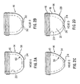
- Fig. 2D depicts a pressure head 14 having at one end thereof a threaded end 16; preferably the threads are on the exterior wall 18 of the head 14, although the threads may also be along the interior wall 20.
- the interior of the head 14 forms a reservoir 22.
- the head 14, at the end opposite threaded end 16, includes a bottom portion 24 which may be circular, elliptical, square, rectangular or other shape.
- An aperture 26 is formed through the portion 24 to form a communication channel to the reservoir 22.
- the radius of curvature 28 of the exterior wall 18 near the bottom portion 24 is 0.45 inches (11.43 mm), the bottom portion 24 being circular and having a diameter of 0.25 inches (6.35 mm), and the aperture being circular and having a diameter of 0.10 inches (2.54 mm).
- the radius of curvature of the exterior wall 18 near the bottom portion 24 has an effect on the quantities of interstitial fluids that can be collected from a microporation site.
- Fig. 2B depicts a pressure head 14, referred to below as "Head B", which is similar to that shown in Fig. 2D; however, the bottom portion 30 of the pressure head of Fig. 2B is concave and has a radius of curvature 32 of 0.50 inches (12.7 mm), with the concave portion having a diameter of 0.311 inches (7.9 mm).
- Fig. 2C depicts a pressure head 14, referred to below as "Head C”.
- the exterior wall 18 of Head C has a radius of curvature 34 of 0.75 inches (19.05 mm) and the interior wall 30 of Head C has a corresponding radius of curvature 36 of 0.650 inches (16.51 mm).
- the bottom portion 24 of the head 14 of Fig. 2C is circular and has a diameter of 0.25 inches (6.35 mm).
- Fig. 2A depicts pressure head 14, referred to below as "Head A”.
- the exterior wall 18 of Head A has a radius of curvature 38 of 0.45 inches (11.43 mm) and the interior wall 20 of Head A has a radius of curvature 40 of 0.361 inches (9-17 mm).
- the bottom portion 24 of the head 14 of Fig. 2A has a diameter of 0.377 inches (9.58 mm).
- Fig. 2E depicts pressure head 14, referred to below as "Head E".
- the bottom portion 24 of the head 14 of Fig. 2A is circular and has a diameter of 9.5 mm.
- Fig. 2F depicts pressure head 14, referred to below as "Head F".
- the bottom portion 24 of the head 14 of Fig. 2F has a diameter of 9.5 mm.
- Fig. 2G depicts pressure head 14, referred to below as "Head G".
- the bottom portion 24 of the head 14 of Fig. 2G has a diameter of 5.7 mm.
- the method of the present invention includes the steps of forming a breach through the stratum corneum and into the epidermal layer, followed by the application of a positive pressure to the area surrounding the microporation site to cause interstitial fluids to exude therefrom.
- the interstitial fluids are then collected.
- the fluids can then be analyzed to determine the concentration of an analyte, such as glucose.
- one specific method for the collection of interstitial fluids from the body of an animal comprises the steps of:
- Another specific method for the collection of interstitial fluids from the body of an animal comprises the steps of:
- each volunteer was used.
- the interior forearms (between the elbow and the wrist) of each volunteer were subject to laser microporation (wavelength of 810 nm, 20 millisecond pulse width, approximately 250 milliwatts, 20 to 30 pulses applied, black tape applied to the skin to act as an energy absorber) to form a microporation site similar to microporation site 10 shown in Fig. 1
- Two such sites were made on each arm of each subject and were hydrated with a water droplet placed on the microporation site for 10 to 15 seconds, followed by drying (using gentle blotting) prior to fluid extraction.
- a total of four microporation sites were made on each subject.
- Head D Fig. 2D
- Head D was manually placed over the microporation site so that the aperture 26 encompassed the site.
- Manual pressure was exerted on Head D in a direction toward the microporation site for sixty (60) seconds.
- Interstitial fluids flowed into Head D and were collected by means of 1 ⁇ l capillary tubes, with the collected volume recorded. By means of this technique, the volume of interstitial fluids recovered ranged from 0.34 to 1 ⁇ l.
- the second site on the right arm and the corresponding second site on the left arm of each subject were treated as follows.
- a vacuum system, -7.5 psig (15 inches of Hg) was applied to each microporation site for 60 seconds.
- Interstitial fluids were observed to flow from the microporation site and were collected by means of 1 ⁇ l capillary tubes, with the collected volume recorded.
- the interstitial fluids (hereinafter "ISF") collected by the application of positive pressure were thereafter analyzed for glucose levels. It is to be noted that for each use of the vacuum assist technique, the volume of interstitial fluids recovered was in the range of 0.1 to 0.2 ⁇ l and no glucose determination was made. As a control, a finger stick was also performed on each volunteer and approximately 50 ⁇ l of blood was withdrawn. The blood samples were centrifuged and the plasma analyzed for glucose values. Table 1 below presents the results of this example.
- the glucose values measured from the collected ISF are reasonably correlated to the glucose values obtained from the blood plasma.
- This example also demonstrates that the volume of ISF that can be obtained by the positive pressure technique disclosed herein is significantly greater than that obtained when using the vacuum method.
- Example 2 Two microporation sites, similar to Fig. 1, were made on each arm (left and right) of seven (7) human volunteers by means of the technique of Example 1.
- the microporation sites were hydrated as in Example 1 and were treated as follows. To one site on one arm (e. g., the right arm), Head D was applied, under manual pressure, for 60 seconds, ISF was collected, and the volume recorded. Thereafter, within two to five minutes, a vacuum system was used to apply a vacuum (13 inches Hg) to the same site for 60 seconds, ISF was collected, and the volume recorded. This pressure/vacuum technique was then applied to the corresponding site on the volunteer's left arm.
- the vacuum system was first applied (13 inches Hg) for 60 seconds, ISF was collected, and the volume recorded. Thereafter, within two to five minutes, Head D was applied, under manual pressure, for 60 seconds to the same site, ISF was collected, and the volume recorded. This vacuum/pressure technique was then applied to the corresponding site on the volunteer's left arm in the same manner. Table 2 below presents the results of this example.
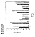
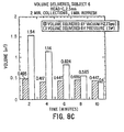
- Fig. 4 presents these data in a slightly different form.
- the average volume of ISF recovered from the right arm through the application of pressure is shown in the left most bar as 0.70 ⁇ l. This value is obtained from the foregoing table, where the ISF collected by the pressure technique is 0.79 ⁇ l and 0.61 ⁇ l from the right arm; the average is 0.70 ⁇ l.
- the remaining data found in Fig. 4 is determined in the same manner. Fig. 4 thus highlights that the use of positive pressure to obtain ISF is superior to vacuum techniques.
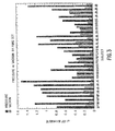
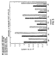
- Fig. 5 is a further depiction of the data of Table 2 and again shows the distinct advantages of using positive pressure to obtain ISF.
- the data are grouped by volunteer, according to the method first applied to collect ISF.
- the left most bar in each data set represents the average volume of ISF collected from both arms of each volunteer during the 60 seconds of pressure application when pressure is applied first.
- volunteer MP this average value of 1.02 ⁇ l is obtained from the Table 2 data for the right and left arms (i. e., 0.79 ⁇ l and 1.25 ⁇ l respectively).
- the second bar represents the average value of ISF collected from both arms of volunteer MP during the 60 seconds of vacuum application when pressure is applied first.
- the third bar represents the average value of ISF collected from both arms of volunteer MP during the 60 seconds of vacuum application when vacuum is applied first, followed by pressure.
- the fourth bar represents the average value of ISF collected from both arms of volunteer MP during the 60 seconds of pressure application when vacuum is applied first.
- Example 1 a further set of studies was performed on five (5) human volunteers.
- microporation sites similar to Fig. 1, were formed on the interior forearm of the volunteer by means of the technique of Example 1; the sites were hydrated as in Example 1.
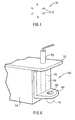
- Head D (see Fig. 2D) was used as the pressure head and was attached to the holder 42 shown in Fig. 6.
- That holder includes a base plate 44 having a threaded opening 46 for engagement with the threaded end 16 of head 14 (shown in dotted lines in Fig. 6).
- the holder 42 also includes a movable vertical plate 48 attached to the base plate 44.
- the movable plate 48 is connected to a ram 50.
- the ram 50 which may be an air driven or hydraulic ram or a biased spring ram, operates to exert a force on the base plate 44, and hence to the threaded end 16 of the head 14.
- the ram 50 as depicted in Fig. 6, is coupled to a top plate 52, which in turn is coupled to a stand 54.
- the stand 54 may also be provided with a tongue (or groove) or other suitable mechanism for engagement with a groove (or tongue) or other suitable mechanism on the movable plate 48, as generally depicted by dotted lines 56 in Fig. 6. Such arrangement permits the movable plate 48 to travel in a repeatable manner when the holder 42 is used.
- the ram may exert a known force to the head 14, which force may be varied from one use of the holder to another or during any single use thereof
- the holder was operated such that a force of 4 through 11 pounds could be applied to the head 14 at the threaded end 16 thereof.
- Example 3 the force applied to the threaded end 16 of Head D was maintained constant during any single run, but was varied from one run to the next. Thus, the following description of the tests performed on Subject 1 applies to the remaining subjects, unless otherwise noted.
- Head D After formation of the microporation site and hydration as in Example 1, Head D, having a circular bottom portion 24 with a diameter of 2.5 mm, was applied to the microporation site using a force of 5 pounds on the threaded end 16. The ISF flux (in ⁇ l/minute) was then measured in 30 second increments over an elapsed time of 6 minutes. Thereafter, Head D was removed from the microporation site. A new microporation site was formed and hydrated as in Example 1 and Head D was applied to this new site using a force of 6 pounds on the threaded end 16. The ISF flux (in ⁇ l/minute) was measured as described, after which Head D was again removed.
- This example also investigated the effect on ISF recovery caused by increasing the diameter of the bottom portion 24 of Head D.
- the procedures described above were used in conjunction with the Head D of Fig. 2D in which the diameter of the bottom portion 24 was 3.0 mm.
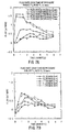
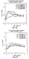
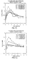
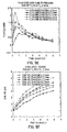
- Figs. 7A through 7J depict the results of this example, in which the flux rate of ISF is plotted against time (in minutes) for the applied forces and where the figures represent the diameters of the bottom portion 24 of Head D as described in the following Table 4.
- Figs. 7A, 7C, 7E, 7G, and 7I it will be noted that, in most instances for each force applied, the rate of ISF flow increases for the first 60 seconds that the force is applied and then tends to decrease thereafter. However, there are some variations from subject to subject and, to a more limited extent, within the subjects themselves. The same general observations can be made from Figs. 7B, 7D, 7F, 7H, and 7J.
- Example 3 Subjects 1, 3, and 6 of Example 3 were used to test the recovery rate of the ISF using a vacuum followed by the application of positive pressure.
- a microporation site was prepared and hydrated by means of the technique of Example 1 and the volume of recovered ISF was measured.
- ISF was collected for 120 seconds using vacuum (-12.73 psig), immediately followed by vacuum removal for 60 seconds for site recovery. After recovery, vacuum (-12.73 psig) was again applied for 120 seconds, followed by 60 seconds of site recovery (vacuum removed). This procedure was repeated five times using vacuum assistance. Each subject was then allowed a five minute recovery period, following which ISF was collected for 120 seconds using Head C with a force of 7 pounds applied to the threaded end 16 of Head C.
- Head C was removed from the microporation site for 60 seconds to allow for recovery.
- ISF collection was performed for 120 seconds using Head C with a force of 7 pounds applied to the threaded end 16 of Head D.
- Head C was removed for another recovery period of 60 seconds. Collection in this manner using positive pressure was carried out five times over the period.
- Figs. 8A through 8C The results of this example are shown in Figs. 8A through 8C. From Figs. 8A through 8C, it is noted that the volume of ISF collected from each subject using the vacuum approach remained substantially constant over the test period, although the volume collected from Subject 3 decreased at 8 minutes and 10 minutes.
- the volume collected from each subject upon the application of positive pressure generally decreased over the entire test period of 10 minutes. It is thus theorized that the ISF in the epidermis exists in equilibrium with fluids in the underlying dermal layer and the surrounding tissues. Removing large quantities of ISF from the epidermis and dermis over a relatively short period of time, without providing a sufficient recovery period, upsets this equilibrium and depletes the ISF residing in the epidermis and dermis of the treated area. Indeed, in connection with the present invention, it has been observed that when a recovery period of on the order of 3 to 8 minutes is used, the next removal of ISF by application of positive pressure will be of a high volume. For example, with reference to Fig.
- Heads A through D (see Figs. 2A-2D), each having an aperture diameter of 2.5 mm, were used to collect ISF from Subject 1 of Example 3.
- a microporation site was prepared by means of the technique of Example 1 and ISF was collected by means of the technique described in Example 3.
- the rate of ISF removal and the volume of ISF removed was measured.
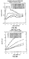
- Figs. 9A through 9H set forth the flux rate and cumulative recovered volume data obtained in this example.
- the Head C generally provides the greatest initial flow (i. e., slope) of ISF over the first 60 seconds as compared to Heads A, B and D.
- the Head C also provides the greatest volume of ISF collected over all applied pressures as compared to the other heads.
- Example 3 Six different head configurations were used to extract ISF. Twelve microporation sites, similar to those of Fig.1, were made on the interior forearms of five human volunteers by means of the technique of Example 1. Heads were attached to the holder 42 shown in Fig. 6. Head A was attached to the holder and was used to apply four (4) pounds force to the microporation site in the same manner as in Example 3. Another microporation site was then formed and head A was used to apply six (6) pounds of force to the microporation site. This process was repeated in this fashion until all heads, A B, C, D, E, and F were used on each subject. In each case, the ram fixture was used as in Example 3. ISF flux (in ⁇ l/minute) was then measured in 30-second increments over a five-minute period.
- Table 5 shows the results of this experiment, including the average amount of ISF collected for all five subjects, for the times of 30 seconds and 60 seconds. Table 5 also shows the percentage of the total amount of ISF collected in 60 seconds that was collected in the first 30 seconds. This percentage indicates how quickly the rate of collection increases to its maximum and is pertinent because it is desirable for the instrument to collect the fluid in a short amount of time. Head Force (pounds) Average volume collected ( ⁇ l) Std. Dev.
- microporation sites were made on the interior forearms of six human volunteers.
- the micropores were arranged (a) singly, (b) in a straight line separated by 1 mm, or (c) in a triangle with each micropore forming a vertex of an equilateral triangle 1 mm on each side.
- Heads C, E, and G were used.
- the force was either four (4) pounds or seven (7) pounds for each combination of pore number and head.
- a fixture similar to the ram fixture was used, but instead of compressed air, this fixture utilized a system of weights applied to the top of the ram to deliver the force. This change was made to increase the accuracy of the force delivery and to reduce friction in the force delivery device. Fluid was collected for one minute at intervals of 30 second (if possible) and the volume collected was calculated.
- Table 6 below shows the results of this example, including the average amount of ISF collected for all five subjects, for the times of 30 seconds and 60 seconds. Table 6 also shows the percentage of the total amount of ISF collected in 60 seconds that was collected in the first 30 seconds This percentage indicates how quickly the rate of collection increases to its maximum and is pertinent because it is desirable for the instrument to collect the fluid in a short amount of time.
- the final column shows the increase in volume of fluid collected in one minute in the presence of additional micropores relative to volume of fluid collected in the presence of a single micropore. In general terms, the percentage increase in going from one micropore to two micropores was greater than the percentage increase in going from two micropores to three micropores. This was especially true of the more aggressive heads (head E and head G).
- This example shows the effect of aperture diameter on the amount of fluid collected and the rate at which [the greatest percentage of fluid] is recovered.
- 11 head configurations were tested on the interior forearm of five subjects. The configurations were as follows: Head Diameter of aperture (mm) C 1.5 C 2.5 C 3.0 C 4.0 E 1.5 E 2.5 E 3.0 E 4.0 G 1.5 G 2.5 G 3.0
- micropores were arranged in a triangle, with each micropore forming a vertex of an equilateral triangle 1 mm on each side.
- Four pounds of force was used for each extraction.
- Each extraction had a duration of 60 seconds, with samples being collected at 30 and 60 seconds.
- Table 7 shows the results of this experiment, including the average amount of ISF collected for all five subjects, for the times of 30 seconds and 60 seconds Table 7 also shows the percentage of the total amount of ISF collected in 60 seconds that was collected in the first 30 seconds. This percentage indicates how quickly the rate of collection increases to its maximum and is pertinent because it is desirable for the instrument to collect the fluid in a short amount of time.
- This example shows that varying the diameter of the aperture at the center of the head can result in significant changes in the volume of fluid collected and flux rates. The smaller the aperture, the faster the ISF is collected, but a lower total volume is collected. At the largest aperture tested (4 mm), the fluid flux rate had significantly decreased, and total volume of ISF collected differed significantly from that when optimum size was used. The optimum size was found to be 2.5 mm to 3.0 mm with these head configurations.
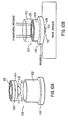
- FIGs. 10A and 10B show an apparatus that employs a vacuum to cause atmospheric pressure to act upon a piston in a cylinder and cause it to apply a force to the skin.
- the apparatus allows the user, i e., the patient, to apply force to a body part, such as a forearm, without the need for providing an opposing force to inhibit motion.
- a stopping mechanism is required to oppose the applied force and keep the body part stationary.
- An apparatus that exerts a force on the skin of the forearm normally requires a means for supporting the backside of the arm, typically through the use of a mechanical clamp or an immovable object, such as a table. These means are large and uncomfortable for the user, or they require proper technique to provide consistent results.
- the apparatus shown in Figs. 10A and 10B can be made in small sizes. It is less constraining than a clamp or a strap or a band because it does not need to surround the site of interest on the body part. This apparatus is more comfortable than other apparatus currently used to apply force to the skin.
- this apparatus Unlike a clamp or a strap or a band, this apparatus will not cause blood vessels to collapse. Because the apparatus requires access to only one surface of a body part of a subject, it can be applied to virtually any site for obtaining samples of interstitial fluids, such as the arm, thigh, or waist, without any modifications.
- the apparatus 100 comprises a cylinder 102 and a piston 104.
- the piston 104 comprises a seal 106 and a pressure head 108.
- the pressure head 108 has a bottom portion 109, which has a small aperture 110 at the lowermost point thereof.
- the pressure head 108 also contains a reservoir 112.
- the cylinder 102 has a vacuum port 114.
- the purpose of the cylinder 102 is to position the apparatus over the site from which interstitial fluids are to be collected.
- the purpose of the piston 104 is to apply sufficient force to the skin to cause interstitial fluids to emerge therefrom.
- the purpose of the seal 106 is to maintain the vacuum at a level sufficient for causing the piston 104 to apply sufficient pressure to the skin.
- the purpose of the pressure head 108 is to provide contact with the skin at the point of application of force.
- the pressure head 108 has a small aperture 110, through which the interstitial fluid can flow for collection in the reservoir 112.
- a breach is formed in the stratum corneum by one of the techniques described previously.
- the apparatus 100 is placed over the breach, with the cylinder 102 being in contact with the skin so that the aperture 110 is in register with the breach in the stratum corneum.
- the vacuum is applied via a pump or the like (not shown) through the vacuum port 114.
- the piston 104 is caused to travel downwards against the skin because of atmospheric pressure acting on the upper surface 116 of the piston 104. See Fig. 10B.
- the positive pressure exerted on the skin by the pressure head 108 causes interstitial fluids to flow through the breach in the stratum corneum and through the aperture 110 and collect in the reservoir 112.
- the fluid can then be analyzed determine the concentration of analyte.
- the apparatus 100 is placed over the skin, with the cylinder 102 being in contact with the skin.
- a breach is then formed in the stratum corneum so that the aperture 110 is in register with the breach in the stratum corneum.
- pressure can be applied to the skin prior to forming the breach in the stratum corneum.
- the vacuum is applied via a pump or the like (not shown) through the vacuum port 114.
- the piston 104 is caused to travel downwards against the skin because of atmospheric pressure acting on the upper surface 118 of the piston 104. See Fig. 10B.
- the positive pressure exerted on the skin by the pressure head 108 causes interstitial fluids to flow through the breach in the stratum corneum and through the aperture 110 and collect in the reservoir 112.
- the fluid can then be analyzed determine the concentration of analyte. Variations of these specific procedures can also be used.
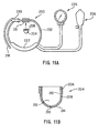
- a pressure cuff can be used to apply force and pressure to a body part in which a breach of the stratum corneum has been formed so that interstitial fluids can be collected from the breach.
- the pressure cuff is substantially similar to the pressure cuffs used to measure a person's blood pressure.
- the pressure cuff comprises a strap or band that is designed to surround the site of interest on the body part.
- a pressure cuff 200 comprises a band 202 to which is attached a pressure head 204. The purpose of the pressure head 204 is to provide contact with the skin at the point of application of force.
- the band 202 comprises a means 211 for securing the pressure head 204. If the pressure head 204 utilizes threads, the securing means 211 preferably also uses threads
- the interior of the pressure head 204 forms a reservoir 212.
- a bottom portion 214 which may be circular, elliptical, square, rectangular or other shape.
- An aperture 216 is formed through the bottom portion 214 to form a communication channel to the reservoir 212.
- a breach is formed in the stratum corneum of the body part, preferably the forearm, by one of the techniques described previously.
- the band 202 is placed around the body part so that the pressure head 204 is directly over the breach, so that the aperture 216 is in register with the breach in the stratum corneum.
- the band 202 has an end 218, which is inserted through a buckle 220.
- the end 218 of the band 202 can be pulled to tighten the band 202 around the site of interest on the body part.
- the band 202 can be tightened further by increasing the pressure within a bladder 222, located on the band 202.
- the pressure can be increased in the bladder 222 by supplying air from a pump 224.
- the increase in pressure can be monitored by a pressure gauge 226
- the band 202 should be tightened sufficiently so that the pressure head 204 applies a force to the skin sufficient to cause interstitial fluids to flow through the breach in the stratum corneum and through the aperture 216 and collect in the reservoir 212.
- the fluid can then be analyzed determine the concentration of an analyte.
- the band 202 is placed around the body part.
- a breach is formed in the stratum corneum of the body part, preferably the forearm, so that the aperture 216 is in register with the breach in the stratum corneum.
- pressure can be applied to the skin prior to forming the breach in the stratum corneum.
- the end 218 of the band 202 can be pulled to tighten the band 202 around the site of interest on the body part.
- the band 202 can be tightened further by increasing the pressure within a bladder 222, located on the band 202.
- the pressure can be increased in the bladder 222 by supplying air from a pump 224.
- the increase in pressure can be monitored by a pressure gauge 226.
- the band 202 should be tightened sufficiently so that the pressure head 204 applies a force to the skin sufficient to cause interstitial fluids to flow through the breach in the stratum corneum and through the aperture 216 and collect in the reservoir 212.
- the fluid can then be analyzed determine the concentration of analyte. Variations of these specific procedures can also be used.
Landscapes
- Health & Medical Sciences (AREA)
- Life Sciences & Earth Sciences (AREA)
- Molecular Biology (AREA)
- General Health & Medical Sciences (AREA)
- Engineering & Computer Science (AREA)
- Biomedical Technology (AREA)
- Heart & Thoracic Surgery (AREA)
- Medical Informatics (AREA)
- Physics & Mathematics (AREA)
- Surgery (AREA)
- Animal Behavior & Ethology (AREA)
- Pathology (AREA)
- Public Health (AREA)
- Veterinary Medicine (AREA)
- Hematology (AREA)
- Optics & Photonics (AREA)
- Biophysics (AREA)
- Investigating Or Analysing Biological Materials (AREA)
- Measurement Of The Respiration, Hearing Ability, Form, And Blood Characteristics Of Living Organisms (AREA)
Applications Claiming Priority (3)
| Application Number | Priority Date | Filing Date | Title |
|---|---|---|---|
| US6543197P | 1997-10-21 | 1997-10-21 | |
| US65431P | 1997-10-21 | ||
| EP98953739A EP1017320A1 (fr) | 1997-10-21 | 1998-10-20 | Appareil et procede pour la collecte de fluides interstitiels |
Related Parent Applications (1)
| Application Number | Title | Priority Date | Filing Date |
|---|---|---|---|
| EP98953739.4 Division | 1998-10-20 |
Publications (2)
| Publication Number | Publication Date |
|---|---|
| EP1598014A2 true EP1598014A2 (fr) | 2005-11-23 |
| EP1598014A3 EP1598014A3 (fr) | 2005-12-14 |
Family
ID=35125983
Family Applications (1)
| Application Number | Title | Priority Date | Filing Date |
|---|---|---|---|
| EP05106174A Withdrawn EP1598014A3 (fr) | 1997-10-21 | 1998-10-20 | Appareil pour la collecte de fluids interstitiels |
Country Status (1)
| Country | Link |
|---|---|
| EP (1) | EP1598014A3 (fr) |
Cited By (2)
| Publication number | Priority date | Publication date | Assignee | Title |
|---|---|---|---|---|
| WO2011076640A1 (fr) * | 2009-12-22 | 2011-06-30 | St. Jude Medical Systems Ab | Dispositif de compression fémorale |
| CN116509458A (zh) * | 2023-03-13 | 2023-08-01 | 深圳大学 | 一种基于微针阵列的负压式快速提取储存组织液的装置 |
Family Cites Families (3)
| Publication number | Priority date | Publication date | Assignee | Title |
|---|---|---|---|---|
| US4517978A (en) * | 1983-01-13 | 1985-05-21 | Levin Paul D | Blood sampling instrument |
| EP0462088B1 (fr) * | 1990-06-11 | 1995-11-08 | Radi Medical Systems Ab | Dispositif de compression du fémur |
| US5879367A (en) * | 1995-09-08 | 1999-03-09 | Integ, Inc. | Enhanced interstitial fluid collection |
-
1998
- 1998-10-20 EP EP05106174A patent/EP1598014A3/fr not_active Withdrawn
Cited By (2)
| Publication number | Priority date | Publication date | Assignee | Title |
|---|---|---|---|---|
| WO2011076640A1 (fr) * | 2009-12-22 | 2011-06-30 | St. Jude Medical Systems Ab | Dispositif de compression fémorale |
| CN116509458A (zh) * | 2023-03-13 | 2023-08-01 | 深圳大学 | 一种基于微针阵列的负压式快速提取储存组织液的装置 |
Also Published As
| Publication number | Publication date |
|---|---|
| EP1598014A3 (fr) | 2005-12-14 |
Similar Documents
| Publication | Publication Date | Title |
|---|---|---|
| US6786874B2 (en) | Apparatus and method for the collection of interstitial fluids | |
| US6063039A (en) | Method and apparatus for obtaining blood for diagnostic tests | |
| US6027459A (en) | Method and apparatus for obtaining blood for diagnostic tests | |
| EP1245187B1 (fr) | Anneau de pression fendu pour lancette et dispositif de prélèvement de sang | |
| US5458140A (en) | Enhancement of transdermal monitoring applications with ultrasound and chemical enhancers | |
| US10631771B2 (en) | Methods and apparatus for blood sampling | |
| CN100515336C (zh) | 用于穿刺装置的盖件 | |
| US7758516B2 (en) | Method and apparatus for sampling bodily fluid | |
| US8696596B2 (en) | Blood and interstitial fluid sampling device | |
| US8366729B2 (en) | Lancing device and method of sample collection | |
| US6793633B2 (en) | Blood and interstitial fluid sampling device | |
| US6048352A (en) | Disposable element for use in a body fluid sampling device | |
| US20110046515A1 (en) | Methods and apparatus for expressing body fluid from an incision | |
| JP2004522500A5 (fr) | ||
| GB2325167A (en) | Blood and interstitial fluid sampling device | |
| CA2376285A1 (fr) | Dispositif a jeu de microaiguilles intradermiques | |
| JP2002503119A (ja) | 切開部から体液を絞り出す方法及び装置 | |
| AU2001266766A1 (en) | Cap for a lancing device | |
| JP2002512834A (ja) | 切開部から体液を吸引・汲み出しする方法及び装置 | |
| AU2002314648B2 (en) | Non-invasive transudate extraction | |
| EP1598014A2 (fr) | Appareil pour la collecte de fluids interstitiels | |
| WO1999020181A1 (fr) | Appareil et procede pour la collecte de fluides interstitiels | |
| CN2238620Y (zh) | 皮下组织切吸治疗装置 | |
| CA2733803A1 (fr) | Embout pour dispositif a lancette |
Legal Events
| Date | Code | Title | Description |
|---|---|---|---|
| PUAI | Public reference made under article 153(3) epc to a published international application that has entered the european phase |
Free format text: ORIGINAL CODE: 0009012 |
|
| PUAL | Search report despatched |
Free format text: ORIGINAL CODE: 0009013 |
|
| AC | Divisional application: reference to earlier application |
Ref document number: 1017320 Country of ref document: EP Kind code of ref document: P |
|
| AK | Designated contracting states |
Kind code of ref document: A2 Designated state(s): AT BE CH DE ES FR GB IT LI NL |
|
| AK | Designated contracting states |
Kind code of ref document: A3 Designated state(s): AT BE CH DE ES FR GB IT LI NL |
|
| AKX | Designation fees paid | ||
| STAA | Information on the status of an ep patent application or granted ep patent |
Free format text: STATUS: THE APPLICATION IS DEEMED TO BE WITHDRAWN |
|
| 18D | Application deemed to be withdrawn |
Effective date: 20060615 |
|
| REG | Reference to a national code |
Ref country code: DE Ref legal event code: 8566 |