EP1598005B1 - Device for determining hemodynamic parameters - Google Patents
Device for determining hemodynamic parameters Download PDFInfo
- Publication number
- EP1598005B1 EP1598005B1 EP05102713A EP05102713A EP1598005B1 EP 1598005 B1 EP1598005 B1 EP 1598005B1 EP 05102713 A EP05102713 A EP 05102713A EP 05102713 A EP05102713 A EP 05102713A EP 1598005 B1 EP1598005 B1 EP 1598005B1
- Authority
- EP
- European Patent Office
- Prior art keywords
- pressure
- function
- svr
- map
- diastole
- Prior art date
- Legal status (The legal status is an assumption and is not a legal conclusion. Google has not performed a legal analysis and makes no representation as to the accuracy of the status listed.)
- Active
Links
- 230000000004 hemodynamic effect Effects 0.000 title description 11
- 230000006870 function Effects 0.000 claims description 35
- 238000005259 measurement Methods 0.000 claims description 20
- 230000004872 arterial blood pressure Effects 0.000 claims description 11
- 238000004458 analytical method Methods 0.000 claims description 10
- 238000004364 calculation method Methods 0.000 claims description 9
- 230000009885 systemic effect Effects 0.000 claims description 8
- 230000007704 transition Effects 0.000 claims description 8
- 230000000747 cardiac effect Effects 0.000 claims description 6
- 238000012937 correction Methods 0.000 claims description 6
- 230000004882 diastolic arterial blood pressure Effects 0.000 claims description 5
- 230000001435 haemodynamic effect Effects 0.000 claims description 5
- 210000000709 aorta Anatomy 0.000 claims description 3
- 238000009530 blood pressure measurement Methods 0.000 claims description 3
- 230000015654 memory Effects 0.000 claims description 3
- 238000011156 evaluation Methods 0.000 claims 5
- 230000004069 differentiation Effects 0.000 claims 1
- 230000036581 peripheral resistance Effects 0.000 description 27
- 230000035487 diastolic blood pressure Effects 0.000 description 7
- 230000002792 vascular Effects 0.000 description 3
- 102100023174 Methionine aminopeptidase 2 Human genes 0.000 description 2
- 108090000192 Methionyl aminopeptidases Proteins 0.000 description 2
- 230000006978 adaptation Effects 0.000 description 2
- 238000013459 approach Methods 0.000 description 2
- 210000001367 artery Anatomy 0.000 description 2
- 238000002347 injection Methods 0.000 description 2
- 239000007924 injection Substances 0.000 description 2
- 230000010354 integration Effects 0.000 description 2
- 238000007562 laser obscuration time method Methods 0.000 description 2
- 238000012417 linear regression Methods 0.000 description 2
- 238000000034 method Methods 0.000 description 2
- 238000012545 processing Methods 0.000 description 2
- 230000035485 pulse pressure Effects 0.000 description 2
- YREOLPGEVLLKMB-UHFFFAOYSA-N 3-methylpyridin-1-ium-2-amine bromide hydrate Chemical compound O.[Br-].Cc1ccc[nH+]c1N YREOLPGEVLLKMB-UHFFFAOYSA-N 0.000 description 1
- 210000002376 aorta thoracic Anatomy 0.000 description 1
- 239000003795 chemical substances by application Substances 0.000 description 1
- 238000011157 data evaluation Methods 0.000 description 1
- 238000010586 diagram Methods 0.000 description 1
- 230000003205 diastolic effect Effects 0.000 description 1
- 238000013213 extrapolation Methods 0.000 description 1
- 238000009499 grossing Methods 0.000 description 1
- 238000012544 monitoring process Methods 0.000 description 1
- 230000000737 periodic effect Effects 0.000 description 1
- 230000002093 peripheral effect Effects 0.000 description 1
- 230000004962 physiological condition Effects 0.000 description 1
- 230000004088 pulmonary circulation Effects 0.000 description 1
- 239000000243 solution Substances 0.000 description 1
- 230000001839 systemic circulation Effects 0.000 description 1
- 230000035488 systolic blood pressure Effects 0.000 description 1
- 230000002123 temporal effect Effects 0.000 description 1
- 230000003936 working memory Effects 0.000 description 1
Images

Classifications
-
- A—HUMAN NECESSITIES
- A61—MEDICAL OR VETERINARY SCIENCE; HYGIENE
- A61B—DIAGNOSIS; SURGERY; IDENTIFICATION
- A61B5/00—Measuring for diagnostic purposes; Identification of persons
- A61B5/02—Detecting, measuring or recording pulse, heart rate, blood pressure or blood flow; Combined pulse/heart-rate/blood pressure determination; Evaluating a cardiovascular condition not otherwise provided for, e.g. using combinations of techniques provided for in this group with electrocardiography or electroauscultation; Heart catheters for measuring blood pressure
- A61B5/026—Measuring blood flow
- A61B5/029—Measuring or recording blood output from the heart, e.g. minute volume
-
- A—HUMAN NECESSITIES
- A61—MEDICAL OR VETERINARY SCIENCE; HYGIENE
- A61B—DIAGNOSIS; SURGERY; IDENTIFICATION
- A61B5/00—Measuring for diagnostic purposes; Identification of persons
- A61B5/02—Detecting, measuring or recording pulse, heart rate, blood pressure or blood flow; Combined pulse/heart-rate/blood pressure determination; Evaluating a cardiovascular condition not otherwise provided for, e.g. using combinations of techniques provided for in this group with electrocardiography or electroauscultation; Heart catheters for measuring blood pressure
- A61B5/02028—Determining haemodynamic parameters not otherwise provided for, e.g. cardiac contractility or left ventricular ejection fraction
-
- A—HUMAN NECESSITIES
- A61—MEDICAL OR VETERINARY SCIENCE; HYGIENE
- A61B—DIAGNOSIS; SURGERY; IDENTIFICATION
- A61B5/00—Measuring for diagnostic purposes; Identification of persons
- A61B5/02—Detecting, measuring or recording pulse, heart rate, blood pressure or blood flow; Combined pulse/heart-rate/blood pressure determination; Evaluating a cardiovascular condition not otherwise provided for, e.g. using combinations of techniques provided for in this group with electrocardiography or electroauscultation; Heart catheters for measuring blood pressure
- A61B5/021—Measuring pressure in heart or blood vessels
- A61B5/02108—Measuring pressure in heart or blood vessels from analysis of pulse wave characteristics
-
- A—HUMAN NECESSITIES
- A61—MEDICAL OR VETERINARY SCIENCE; HYGIENE
- A61B—DIAGNOSIS; SURGERY; IDENTIFICATION
- A61B5/00—Measuring for diagnostic purposes; Identification of persons
- A61B5/02—Detecting, measuring or recording pulse, heart rate, blood pressure or blood flow; Combined pulse/heart-rate/blood pressure determination; Evaluating a cardiovascular condition not otherwise provided for, e.g. using combinations of techniques provided for in this group with electrocardiography or electroauscultation; Heart catheters for measuring blood pressure
- A61B5/021—Measuring pressure in heart or blood vessels
- A61B5/0215—Measuring pressure in heart or blood vessels by means inserted into the body
-
- A—HUMAN NECESSITIES
- A61—MEDICAL OR VETERINARY SCIENCE; HYGIENE
- A61B—DIAGNOSIS; SURGERY; IDENTIFICATION
- A61B5/00—Measuring for diagnostic purposes; Identification of persons
- A61B5/02—Detecting, measuring or recording pulse, heart rate, blood pressure or blood flow; Combined pulse/heart-rate/blood pressure determination; Evaluating a cardiovascular condition not otherwise provided for, e.g. using combinations of techniques provided for in this group with electrocardiography or electroauscultation; Heart catheters for measuring blood pressure
- A61B5/026—Measuring blood flow
- A61B5/0275—Measuring blood flow using tracers, e.g. dye dilution
- A61B5/028—Measuring blood flow using tracers, e.g. dye dilution by thermo-dilution
Definitions
- the present invention relates to a device for determining a hemodynamic parameter of a patient by means of pulse contour analysis.
- the determination of hemodynamic parameters, in particular of the cardiac output (CO), by means of pulse contour analysis on the basis of a nonlinear model of the windkessel is described in DE 198 14 371 A1 and further literature cited therein.
- the basic measure of the pulse contour analysis is a pressure approximately corresponding to the aortic pressure, which is continuously measured, for example, by means of an arterial catheter in a leg artery.
- a pulse contour analysis system from Pulsion Medical Systems AG is commercially available under the name PiCCO.
- the determination of systemic vascular resistance and compliance involves calibration values that are determined during a calibration measurement and then not changed thereafter.
- This calibration measurement comprises the determination of a calibration value of the hereditary volume by means of transpulmonary thermodilution measurement.
- PCCO Pulse Contour Cardiac Output
- HR heart rate
- SV stroke volume
- the stroke volume (SV) is determined by integration over a pulse period or over the systole according to the relationship SV ⁇ ⁇ p t SVR + C p ⁇ dp dt ⁇ dt calculated (with time t, pressure p, systemic vascular resistance SVR, compliance C).
- SVR systemic vascular resistance
- the haemodynamic parameters determined by means of pulse contour analysis decrease in quality with increasing duration of patient monitoring (ie from the calibration measurement, ie the probability that the hemodynamic parameter obtained by pulse-scan deviates from the actual physiological conditions by more than a certain predetermined amount , is increasing.
- the calibration measurement can be repeated at shorter intervals by means of thermodilution.
- thermodilution is associated with some effort, in particular with the provision of a bolus injection, which means additional stress for the monitored patient, as well as the medical personnel involved time-consuming and thus reduces its availability for other tasks.
- the publication EP 1 236 435 A1 discloses to use a heatable central venous catheter for the periodic recalibration by means of thermodilution. Although this helps to avoid bolus injections, it increases the amount of equipment considerably.
- the present invention has for its object to provide a device for determining hemodynamic parameters by means of pulse contour analysis, can be dispensed with the use of regular repetition of a calibration by means of thermodilution, and yet provides a measurement data evaluation consistent quality.
- this object is achieved with a device for determining a hemodynamic parameter of a patient by means of pulse contour analysis according to claim 1.
- Preferred embodiments may be designed according to any one of claims 2-17.
- a continuous recalibration of the systemic vascular resistance takes place by means of parameters obtained from the continuously determined pressure measurement data.
- the pulse contouranalytical determination of the cardiac output PCCO can in principle be carried out as described above, but one or more of the parameters which would conventionally be determined in the course of the calibration measurement and then treated as a constant, regularly, preferably once for each pulse period, from the Function p (t) are recalculated.
- the cardiac output CO simple to use the pulcoontanalytically obtained Herzeitvolumen PCCO, but leads to a circulatory relationship. This can in principle be solved by means of an iteration process, which, however, can lead to instabilities in the event of drastic changes in the systemic vascular resistance SVR. Therefore, additional or alternative criteria for changing the systemic vascular resistance SVR are advantageously implemented.
- SVR SVRcal ⁇ ⁇ / ⁇ cal a ⁇ Pd / Pdcal b
- SVRcal is a calibration value of the systemic resistance
- ⁇ cal is a calibration value of the time constant ⁇
- Pd is the diastolic arterial pressure
- Pdcal is a calibration value of the diastolic arterial pressure
- a, b are empirically determined or estimated exponents.
- the calibration values SVRcal, ⁇ cal and Pdcal can be determined as part of a calibration measurement including thermodilution measurement.
- the (arterial) diastolic pressure Pd and the pressure at the transition between systole and diastole Pn are also preferably newly determined on a regular basis, provided that they are needed for the further calculation of hemodynamic parameters. It is particularly advantageous to implement improved ways to determine the transition between systole and diastole, the so-called “Diachrotic Notch", as well as for the determination of diastolic pressure.
- an axis adaptation for the function p (t) is provided in such a way that a typical course of an arterial pressure function obtained from empirically collected data has approximately the shape of a circular arc at the transition between systole and diastole.
- the position of the maximum of the curvature function K is determined. If appropriate, the corresponding point in time is corrected taking into account delay elements in the measurement setup, for example filters. If the maximum of the curvature function K (possibly after this correction) lies within 70% of the duration of the current pulse period (or the duration of a preceding pulse period, if the calculation is carried out in real time before the end of the current pulse period), the location of the ( corrected if necessary) maximum of the curvature function K as the time of transition between systole and diastole understood.
- the transition between systole and diastole is set to 70% of the duration of the current pulse period (or the duration of a previous pulse period, if the calculation is performed in real time before the end of the current pulse period).
- an additional Plausibility check taking into account pulse duration, ejection time, etc. be provided.
- the determination of the curvature function can be dispensed with, and instead of the maximum of the curvature function K, the maximum of the second derivative y "of the function p (t), if appropriate after appropriate correction, can be taken as the time of transition between systole and diastole.
- a linear regression of suitable length is performed.
- a suitable length advantageously about 100 milliseconds or twice the inverse of the measuring frequency can be assumed. If the length of the diastole is shorter than twice that length, the lowest measured pressure is assumed to be the diastolic pressure Pd. Otherwise, the beginning of the regression is shifted by a suitable distance, preferably half the length of the regression, in the direction of the systolic peak and extrapolated in the opposite direction. The intersection of the extrapolation with the extrapolated linear regression of the pressure curve in the region of its maximum slope then dictates the diastolic pressure. For the determination of the range of the maximum slope, preferably only data points within 20% to 80% of the pulse amplitude (highest measured pressure minus the lowest measured pressure of the pulse period) are taken into account.
- the value COTD can be expressed by the expression MAP - CVP / SVR be replaced, the difference between mean arterial pressure MAP and central venous pressure CVP is regularly redetermined. Either the values of the current or previous pulse period can be used, or else average values over a few (for example, between 10 and 50) preceding pulse periods or a few (for example, approximately 30) seconds.
- the mean slope of the pressure curve in the diastole ⁇ dp / dt> is also preferably determined regularly.
- f p 1 / k ⁇ 1 ⁇ p / MAP - k ⁇ 2 - k ⁇ 3 ⁇ p / MAP 2 with empirically determined or estimated coefficients k1, k2, k3.
- other suitable adjustments may exist.
- C p MAP - CVP / SVR ⁇ ⁇ dp / dt > ⁇ f MAP ⁇ p
- f MAP ⁇ p 1 / 1 . 8th ⁇ p / MAP - 0 . 68 - 4 . 5 ⁇ p / MAP 2
- Fig. 1 shows a greatly simplified block diagram of a device according to the invention and a sketched section of the vascular system of a patient.
- the device off Fig. 1 has an input / output subsystem (I / O) with three input channels 1, 2, 3.
- the first input channel 1 is continuously read the aortic pressure of the patient at least approximately corresponding pressure signal. It may be an analog sensor signal, which is digitized by means of an analog-to-digital converter, or it is already a digital signal from an external pressure transducer 4 is read.
- the pressure approximately corresponding to the aortic pressure is advantageously an arterial pressure measured as close to the aorta as possible via an arterial catheter 5.
- a measurement site can serve a leg artery 6, as indicated in the sketched section of the vascular system with heart 7, aortic arch 8, pulmonary circulation 9 and systemic circulation 10th
- the arterial catheter 5 also contains a temperature sensor 11, which can be used for a thermodilution measurement for calibration.
- the digital measurement signal of the associated Temperaturmeßumformers 12 is read in via the second input channel 2.
- the temperature signal can also be read in as an analog signal and digitized by means of an analog-to-digital converter.
- a central venous pressure CVP of the patient at least approximately corresponding pressure signal is read.
- This signal can also be read in analog or digital via a further pressure transducer 13.
- a suitable measuring site is the upper vena cava 15 of the patient.
- the central venous pressure CVP of the patient may also be estimated; Under certain circumstances, an estimate as a constant value is sufficient.
- the inserted central venous catheter 16 has a further lumen 17, via which a cooled bolus for the implementation of the transpulmonary Thermodilution measurement can be injected for calibration.
- the calibration values SVRcal, ⁇ cal and Pdcal for the systemic resistance, the time constant and the diastolic arterial pressure are determined.
- the input / output subsystem (I / O) may include one or more output channels 14, for example, which cooperate with peripherals or the like.
- the signal processing components of the device are interconnected via a central bus (BUS).
- BUS central bus
- the read-in pressure signal is temporarily stored in the working memory (RAM) as a function of the time p (t).
- the function p (t) is processed by the central processing unit (CPU) to calculate the historical volume PCCO and other hemodynamic parameters therefrom.
- a corresponding control program which causes the arithmetic unit (CPU) to carry out the corresponding calculation steps, is stored in a read-only memory (ROM).
- the difference between mean arterial pressure MAP and central venous pressure CVP as well as the mean slope of the pressure curve in diastole ⁇ dp / dt> are redetermined for the current pulse period.
- the correction function f (MAP, pi) is calculated as described above.
- the control program in the read-only memory may of course contain further routines which give the device additional functionalities.
- the function p (t) can be displayed via a display subsystem 18 and the on-time volume PCCO and possibly further hemodynamic parameters can be output.
- the device may be equipped with further components known per se to the person skilled in the art, for example mass storage media for recording raw data and / or calculated hemodynamic parameters.
- the computing unit can with one or more conventional microprocessors, possibly supported by coprocessors to accelerate floating point operations, but also with sogn. digital signal processors (DSP).
- DSP digital signal processors
- Corresponding solutions, as well as further details of the hardware implementation, can be implemented analogously to conventional pulse contour analysis devices according to the prior art.
Landscapes
- Health & Medical Sciences (AREA)
- Life Sciences & Earth Sciences (AREA)
- Cardiology (AREA)
- Medical Informatics (AREA)
- Surgery (AREA)
- Biophysics (AREA)
- Pathology (AREA)
- Engineering & Computer Science (AREA)
- Biomedical Technology (AREA)
- Heart & Thoracic Surgery (AREA)
- Physiology (AREA)
- Molecular Biology (AREA)
- Physics & Mathematics (AREA)
- Animal Behavior & Ethology (AREA)
- General Health & Medical Sciences (AREA)
- Public Health (AREA)
- Veterinary Medicine (AREA)
- Hematology (AREA)
- Vascular Medicine (AREA)
- Measuring Pulse, Heart Rate, Blood Pressure Or Blood Flow (AREA)
- Measuring And Recording Apparatus For Diagnosis (AREA)
Description
Die vorliegende Erfindung betrifft eine Vorrichtung zur Ermittlung eines hämodynamischen Parameters eines Patienten mittels Pulskonturanalyse.The present invention relates to a device for determining a hemodynamic parameter of a patient by means of pulse contour analysis.
Die Bestimmung hämodynamischer Parameter, insbesondere des Herzeitvolumens (Cardiac Output CO), mittels Pulskonturanalyse auf Basis eines nichtlinearen Windkesselmodells ist in
Wesentliche Größen bei der Bestimmung hämodynamischer Parameter ausgehend von der Funktion P(t), d.h. dem zeitlichen Verlauf des dem Aortendruck näherungsweise entsprechenden Drucksignals, sind insbesondere der systemische Gefäßwiderstand (Systemic Vascular Resistance, SVR) sowie ferner auch die sogenannte Compliance (C). Ersterer wird anschaulich als Durchströmungswiderstand des Gefäßsystems des großen Kreislaufs verstanden, letztere als Nachgiebigkeit im Bereich der Aorta. In einem Ersatzschaltbild lassen sich diese Größen als Widerstand und Kapazität darstellen. Insbesondere bei älteren Ansätzen wird die Compliance mitunter vernachlässigt.Significant quantities in determining hemodynamic parameters from function P (t), i. the temporal course of the aortic pressure approximately corresponding pressure signal, in particular the systemic vascular resistance (SVR) and also also the so-called compliance (C). The former is clearly understood as a flow resistance of the vascular system of the large circulatory system, the latter as compliance in the area of the aorta. In an equivalent circuit, these quantities can be represented as resistance and capacitance. Especially with older approaches, compliance is sometimes neglected.
Eine Vorrichtung und ein Verfahren zur Bestimmung der Compliance ist in
Bei herkömmlichen Implementierungen der Pulskonturanalyse gehen in die Bestimmung des systemischen Gefäßwiderstands und der Compliance (wenn diese nicht vernachlässigt wird) Kalibrierwerte ein, welche im Rahmen einer Kalibriermessung ermittelt, und danach nicht mehr geändert werden. Diese Kalibriermessung umfaßt die Bestimmung eines Kalibrierwerts des Herzeitvolumens mittels transpulmonaler Thermodilutionsmessung.In conventional pulse contour analysis implementations, the determination of systemic vascular resistance and compliance (if not neglected) involves calibration values that are determined during a calibration measurement and then not changed thereafter. This calibration measurement comprises the determination of a calibration value of the hereditary volume by means of transpulmonary thermodilution measurement.
Für das mittels Pulskonturanalyse ermittelte Herzeitvolumen (Pulse Contour Cardiac Output PCCO), welches als Produkt aus Pulsfrequenz (Heart Rate, HR) und Schlagvolumen (Stroke Volume, SV) berechnet wird, wird von folgenden Beziehungen Gebrauch gemacht.For Pulse Contour Cardiac Output (PCCO), which is calculated as the product of heart rate (HR) and stroke volume (SV), use is made of the following relationships.
Das Schlagvolumen (SV) wird durch Integration über eine Pulsperiode oder über die Systole gemäß der Beziehung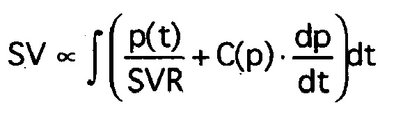
Dabei wird das Integral für jede Pulsperiode k mittels numerischer Integration ausgewertet, worin die Compliance in der Form
Die Parameter COTD, MADCal und <dp/dt>Cal werden nur im Rahmen der Kalibriermessung ermittelt und dann für alle Herzeitvolumen-Berechnungen verwendet.The parameters COTD, MADCal and <dp / dt> Cal are only determined as part of the calibration measurement and then used for all current volume calculations.
Auch für den systemischen Gefäßwiderstand SVR wird ein gemäß der Beziehung ![]()
ermittelter Kalibrierwert eingesetzt (mit MAP:= mittlerem arteriellen Druck [Mean Arterial Pressure], CVP:= zentralvenöser Druck [Central Venous Presseure]), welcher im Rahmen der Kalibriermessung bestimmt und dann für alle Herzeitvolumen-Berechnungen als Konstante verwendet wird.Also for the systemic vascular resistance SVR is one according to the relationship ![]()
determined calibration value (with MAP: = mean arterial pressure, CVP: central venous pressure), which is determined during the calibration measurement and then used for all Herzeitvolumen calculations as a constant.
Es hat sich gezeigt, daß die mittels Pulskonturanalyse ermittelten hämodynamischen Parameter mit zunehmender Dauer der Patientenüberwachung (ab der Kalibriermessung gerechnet mitunter an Qualität abnehmen. D.h. die Wahrscheinlichkeit, daß der pulskonturanalytisch gewonnene hämodynamische Parameter von den tatsächlichen physiologischen Gegebenheiten um mehr als ein bestimmtes vorgegebenes Maß abweicht, nimmt zu.It has been found that the haemodynamic parameters determined by means of pulse contour analysis decrease in quality with increasing duration of patient monitoring (ie from the calibration measurement, ie the probability that the hemodynamic parameter obtained by pulse-scan deviates from the actual physiological conditions by more than a certain predetermined amount , is increasing.
Um dem gegenzusteuem kann die Kalibriermessung mittels Thermodilution in geringeren Abständen wiederholt werden. Dies ist jedoch mit einigem Aufwand, insbesondere mit der Vornahme einer Bolus-Injektion verbunden, was zusätzlichen Streß für den überwachten Patienten bedeutet, sowie das involvierte medizinische Personal zeitlich beansprucht und somit dessen Verfügbarkeit für andere Aufgaben vermindert. Die Druckschrift
Vor dem Hintergrund des obengesagten liegt der vorliegenden Erfindung die Aufgabe zugrunde, eine Vorrichtung zur Ermittlung hämodynamischen Parameter mittels Pulskonturanalyse zu schaffen, bei deren Einsatz auf regelmäßige Wiederholung einer Kalibriermessung mittels Thermodilution verzichtet werden kann, und welche dennoch eine Meßdatenauswertung gleichbleibender Güte liefert.Against the background of the above, the present invention has for its object to provide a device for determining hemodynamic parameters by means of pulse contour analysis, can be dispensed with the use of regular repetition of a calibration by means of thermodilution, and yet provides a measurement data evaluation consistent quality.
Gemäß einem Aspekt der Erfindung wird diese Aufgabe mit einer Vorrichtung zur Ermittlung eines hämodynamischen Parameters eines Patienten mittels Pulskonturanalyse nach Anspruch 1 gelöst.According to one aspect of the invention, this object is achieved with a device for determining a hemodynamic parameter of a patient by means of pulse contour analysis according to claim 1.
Bevorzugte Ausführungsformen können gemäß einem der Ansprüche 2-17 gestaltet sein.Preferred embodiments may be designed according to any one of claims 2-17.
Es erfolgt also gewissermaßen eine fortlaufende Neukalibrierung des systemischen Gefäßwiderstands, vorzugsweise auch der Compliance, mittels aus den kontinuierlich ermittelten Druckmeßdaten gewonnener Parameter.Thus, to a certain extent, a continuous recalibration of the systemic vascular resistance, preferably also the compliance, takes place by means of parameters obtained from the continuously determined pressure measurement data.
Erfindungsgemäß kann die pulskonturanalytische Bestimmung des Herzzeitvolumens PCCO in ihren Grundzügen so erfolgen, wie oben beschrieben, wobei jedoch ein oder mehrere der Parameter, welche herkömmlicherweise im Rahmen der Kalibriermessung bestimmt und dann als Konstante behandelt würden, regelmäßig, vorzugsweise einmal für jede Pulsperiode, aus der Funktion p(t) neuberechnet werden.According to the invention, the pulse contouranalytical determination of the cardiac output PCCO can in principle be carried out as described above, but one or more of the parameters which would conventionally be determined in the course of the calibration measurement and then treated as a constant, regularly, preferably once for each pulse period, from the Function p (t) are recalculated.
Insbesondere für den systemischen Gefäßwiderstand SVR erfolgt hierfür zunächst eine fortlaufende Neuberechnung. Grundsätzlich ist die Größe SVR aus der Beziehung ![]()
![]()
Geeignete Parameter, welche zur Berücksichtigung von Änderungen im systemischen Gefäßwiderstand SVR herangezogen werden können, sind insbesondere:
- der systolische Druck Ps,
- der mittlere arterielle Druck MAP,
- der Pulsdruck (Pulse Pressure) PP = (Ps-Pd),
- die Differenz aus dem Druck am Übergang zwischen Systole und Diastole und dem diastolischen Druck (Pn-Pd),
- mittlere Steigung der Druckkurve in der Diastole <dp/dt>.
- the systolic pressure Ps,
- the mean arterial pressure MAP,
- the pulse pressure PP = (Ps-Pd),
- the difference between the pressure at the transition between systole and diastole and the diastolic pressure (Pn-Pd),
- mean slope of the pressure curve in diastole <dp / dt>.
Die diastolische Phase der Pulsperiode kann vorteilhafterweise durch exponentielles Abfallen angenähert werden:![]()
![]()
![]()
![]()
Für das vereinfachte Ersatzschaltbild einer Parallelschaltung aus Kapazität (Compliance) und Widerstand (systemischer Gefäßwiderstand) gilt:![]()
![]()
Auch wenn diese Beziehungen grundsätzlich ausreichend sind, können die Ergebnisse durch Verwendung empirischer Beziehungen als Funktion der obigen Parameter verbessert werden, insbesondere durch die vorzugsweise angewandte Beziehung![]()
![]()
Auch der (arterielle) diastolische Druck Pd und der Druck am Übergang zwischen Systole und Diastole Pn werden vorzugsweise regelmäßig neu ermittelt, sofern diese für die weitergehende Berechnung hämodynamischer Parameter benötigt werden. Besonders vorteilhaft ist es dabei, verbesserte Wege zur Bestimmung des Übergangs zwischen Systole und Diastole, des sogenannten "Diachrotic Notch", sowie zur Bestimmung des diastolischen Drucks zu implementieren.The (arterial) diastolic pressure Pd and the pressure at the transition between systole and diastole Pn are also preferably newly determined on a regular basis, provided that they are needed for the further calculation of hemodynamic parameters. It is particularly advantageous to implement improved ways to determine the transition between systole and diastole, the so-called "Diachrotic Notch", as well as for the determination of diastolic pressure.
Unter Verwendung geeigneter Glättungsalgorithmen werden die erste (y' = dP/dt) und die zweite Ableitung (y" = d2p/dt2) der Funktion p(t) bestimmt. Aus diesen wird eine Indikationsfunktion berechnet, welche ein Maß für die lokale Krümmung der Funktion p(t) darstellt. Besonders gut geeignet ist die Krümmungsfunktion![]()
![]()
Diese kann als Kehrwert eines lokalen Krümmungsradius aufgefaßt werden. Vorzugsweise ist eine Achsanpassung für die Funktion p(t) vorgesehen dergestalt, daß ein aus empirisch erhobenen Daten gewonnener typischer Verlauf einer arteriellen Druckfunktion am Übergang zwischen Systole und Diastole annähernd die Gestalt eines Kreisbogens besitzt.This can be understood as the reciprocal of a local radius of curvature. Preferably, an axis adaptation for the function p (t) is provided in such a way that a typical course of an arterial pressure function obtained from empirically collected data has approximately the shape of a circular arc at the transition between systole and diastole.
Innerhalb des Bereichs der Funktion p(t), in welchem diese Werte von 90 % bis 10 %, vorzugsweise 75 % bis 10 % ihres Maximalwerts innerhalb der aktuellen Pulsperiode annimmt, wird die Lage des Maximums der Krümmungsfunktion K bestimmt. Der entsprechende Zeitpunkt wird gegebenenfalls noch unter Berücksichtigung von Verzögerungsgliedern im Meßaufbau, beispielsweise Filtern, korrigiert. Liegt das Maximum der Krümmungsfunktion K (ggf. nach dieser Korrektur) innerhalb von 70 % der Dauer der aktuellen Pulsperiode (oder der Dauer einer vorhergehenden Pulsperiode, falls die Berechnung in Echtzeit vor Ende der aktuellen Pulsperiode ausgeführt wird), so wird der Ort des (ggf. korrigierten) Maximums der Krümmungsfunktion K als Zeitpunkt des Übergangs zwischen Systole und Diastole aufgefaßt. Andernfalls wird der Übergang zwischen Systole und Diastole auf 70 % der Dauer der aktuellen Pulsperiode (oder der Dauer einer vorhergehenden Pulsperiode, falls die Berechnung in Echtzeit vor Ende der aktuellen Pulsperiode ausgeführt wird) festgesetzt. Optional kann noch eine zusätzliche Plausibilitätskontrolle unter Berücksichtigung von Pulsdauer, Ausstoßzeit etc. vorgesehen sein.Within the range of the function p (t), in which these values assume from 90% to 10%, preferably 75% to 10%, of their maximum value within the current pulse period, the position of the maximum of the curvature function K is determined. If appropriate, the corresponding point in time is corrected taking into account delay elements in the measurement setup, for example filters. If the maximum of the curvature function K (possibly after this correction) lies within 70% of the duration of the current pulse period (or the duration of a preceding pulse period, if the calculation is carried out in real time before the end of the current pulse period), the location of the ( corrected if necessary) maximum of the curvature function K as the time of transition between systole and diastole understood. Otherwise, the transition between systole and diastole is set to 70% of the duration of the current pulse period (or the duration of a previous pulse period, if the calculation is performed in real time before the end of the current pulse period). Optionally, an additional Plausibility check taking into account pulse duration, ejection time, etc. be provided.
Alternativ kann auf die Bestimmung der Krümmungsfunktion verzichtet werden, und anstelle des Maximums der Krümmungsfunktion K das Maximum der zweiten Ableitung y" der Funktion p(t), ggf. nach entsprechender Korrektur, als Zeitpunkt des Übergangs zwischen Systole und Diastole aufgefaßt werden.Alternatively, the determination of the curvature function can be dispensed with, and instead of the maximum of the curvature function K, the maximum of the second derivative y "of the function p (t), if appropriate after appropriate correction, can be taken as the time of transition between systole and diastole.
Wie oben erwähnt, wird bei der Bestimmung des Schlagvolumens häufig nur über Druckwerte der Systole integriert. Auch um die Genauigkeit der Schlagvolumenbestimmung zu erhöhen, ist daher vorzugsweise obige verbesserte Bestimmung des Übergangs zwischen Systole und Diastole vorgesehen.As mentioned above, when determining the stroke volume, often only pressure values of the systole are integrated. Also, in order to increase the accuracy of the stroke volume determination, it is preferable to provide the above improved determination of the transition between systole and diastole.
Bei der Ermittlung des diastolischen Drucks Pd hat sich der folgende Ansatz als besonders vorteilhaft erwiesen, welcher den Einfluß der limitierten Meßfrequenz berücksichtigt, d.h. der Frequenz, mit welcher das den arteriellen Druck ermittelnde Druckmeßsystem anspricht (und entsprechend als Tiefpaßfilter fungiert):In determining the diastolic pressure Pd, the following approach, which takes into account the influence of the limited measurement frequency, has proved to be particularly advantageous. the frequency with which the pressure measuring system determining the arterial pressure responds (and accordingly acts as a low-pass filter):
Ausgehend vom tiefsten gemessenen Druck wird eine lineare Regression geeigneter Länge vorgenommen. Als geeignete Länge können vorteilhafterweise etwa 100 Millisekunden oder das doppelte des Kehrwerts der Meßfrequenz angenommen werden. Ist die Länge der Diastole kürzer als das doppelte dieser Länge, so wird der tiefste gemessene Druck als diastolischer Druck Pd angenommen. Andernfalls wird der Beginn der Regression um eine geeignete Strecke, vorzugsweise die Hälfte der Länge der Regression, in Richtung des systolischen Peaks verschoben und in die Gegenrichtung extrapoliert. Der Schnittpunkt der Extrapolation mit der extrapolierten linearen Regression der Druckkurve im Bereich ihrer maximalen Steigung gibt dann den diastolischen Druck vor. Für die Ermittlung des Bereichs der maximalen Steigung werden vorzugsweise nur Datenpunkte innerhalb von 20% bis 80% der Pulsamplitude (höchster gemessener Druck minus niedrigstem gemessenen Druck der Pulsperiode) berücksichtigt.Starting from the lowest measured pressure, a linear regression of suitable length is performed. As a suitable length, advantageously about 100 milliseconds or twice the inverse of the measuring frequency can be assumed. If the length of the diastole is shorter than twice that length, the lowest measured pressure is assumed to be the diastolic pressure Pd. Otherwise, the beginning of the regression is shifted by a suitable distance, preferably half the length of the regression, in the direction of the systolic peak and extrapolated in the opposite direction. The intersection of the extrapolation with the extrapolated linear regression of the pressure curve in the region of its maximum slope then dictates the diastolic pressure. For the determination of the range of the maximum slope, preferably only data points within 20% to 80% of the pulse amplitude (highest measured pressure minus the lowest measured pressure of the pulse period) are taken into account.
In der eingangs aufgeführten Berechnungsformel für die Compliance kann der Wert COTD durch den Ausdruck ![]()
![]()
Zu besseren Ergebnissen bei der Ermittlung der Compliance führt vorzugsweise eine Korrekturfunktion der Form![]()
![]()
Für die Compliance ergibt sich also vorzugsweise![]()
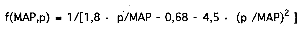
![]()
Grundsätzlich erfindungsgemäß, wenn auch nicht bevorzugt, sind jedoch auch Ausführungen, bei welchen die Parameter der Compliance-Funktion nicht regelmäßig neuberechnet werden, oder die Compliance vernachlässigt wird.However, in principle according to the invention, although not preferred, embodiments in which the parameters of the compliance function are not recalculated regularly or the compliance is neglected.
Nachfolgend wird ein Beispiel einer besonders bevorzugten Ausführungsform der Erfindung anhand der zugehörigen, rein schematisch aufzufassenden Zeichnung näher beschrieben.An example of a particularly preferred embodiment of the invention will be described in more detail below with reference to the associated drawing, which is to be considered purely schematically.
Die Vorrichtung aus
Über den ersten Eingangskanal 1 wird fortlaufend ein dem Aortendruck des Patienten zumindest näherungsweise entsprechendes Drucksignal eingelesen. Es kann sich dabei um ein analoges Sensor-Signal handeln, welches mittels eines Analog-Digital-Wandlers digitalisiert wird, oder aber es wird bereits ein digitales Signal von einem externen Druckmeßumformer 4 eingelesen.About the first input channel 1 is continuously read the aortic pressure of the patient at least approximately corresponding pressure signal. It may be an analog sensor signal, which is digitized by means of an analog-to-digital converter, or it is already a digital signal from an external pressure transducer 4 is read.
In der Praxis dient als dem Aortendruck näherungsweise entsprechender Druck ein vorteilhafterweise möglichst aortennah über einen arteriellen Katheter 5 gemessener arterieller Druck. Als Meßort kann eine Beinarterie 6 dienen, wie angedeutet im skizzierten Ausschnitt des Gefäßsystems mit Herz 7, Aortenbogen 8, Lungenkreislauf 9 und Körperkreislauf 10.In practice, the pressure approximately corresponding to the aortic pressure is advantageously an arterial pressure measured as close to the aorta as possible via an
Der arterielle Katheter 5 enthält ferner einen Temperatursensor 11, welcher für eine Thermodilutionsmessung zur Kalibrierung eingesetzt werden kann. Das digitale Meßsignal des zugehörigen Temperaturmeßumformers 12 wird über den zweiten Eingangskanal 2 eingelesen. Selbstredend kann jedoch auch das Temperatursignal als Analogsignal eingelesen und mittels eines Analog-Digital-Wandlers digitalisiert werden.The
Über den dritten Eingangskanal 3 wird ein den zentralvenösen Druck CVP des Patienten zumindest näherungsweise entsprechendes Drucksignal eingelesen. Auch dieses Signal kann analog oder digital über einen weiteren Druckmeßumformer 13 eingelesen werden. Ein geeigneter Meßort ist die obere Hohlvene 15 des Patienten. Alternativ kann jedoch der zentralvenöse Druck CVP des Patienten auch abgeschätzt werden; unter Umständen genügt dabei eine Abschätzung als konstanter Wert.About the
Der eingesetzte zentralvenöse Katheter 16 weist ein weiteres Lumen 17 auf, über welches ein gekühlter Bolus für die Durchführung der transpulmonalen Thermodilutionsmessung zur Kalibrierung injiziert werden kann. Im Rahmen der Kalibrierung werden, wie oben erläutert, die Kalibrierwerte SVRcal, τcal und Pdcal für den systemischen Widerstand, die Zeitkonstante und den diastolischen arteriellen Druck ermittelt.The inserted central
Das Ein-/Ausgabe-Subsystem (I/O) kann einen oder mehrere Ausgabe- bzw. Steuerkanäle 14 aufweisen, welche beispielsweise dem Zusammenwirken mit Peripheriegeräten oder ähnlichem dienen.The input / output subsystem (I / O) may include one or
Die der Signalverarbeitung dienenden Komponenten der Vorrichtung sind über einen zentralen Bus (BUS) miteinander verbunden.The signal processing components of the device are interconnected via a central bus (BUS).
Das eingelesene Drucksignal wird als Funktion der Zeit p(t) im Arbeitsspeicher (RAM) zwischengespeichert. Die Funktion p(t) wird von der zentralen Recheneinheit (CPU) verarbeitet, um das Herzeitvolumen PCCO und weitere hämodynamische Parameter hieraus zu berechnen. Ein entsprechendes Steuerprogramm, welches die Recheneinheit (CPU) zur Durchführung der entsprechenden Berechnungsschritte veranlaßt, ist in einem Festspeicher (ROM) abgelegt.The read-in pressure signal is temporarily stored in the working memory (RAM) as a function of the time p (t). The function p (t) is processed by the central processing unit (CPU) to calculate the historical volume PCCO and other hemodynamic parameters therefrom. A corresponding control program, which causes the arithmetic unit (CPU) to carry out the corresponding calculation steps, is stored in a read-only memory (ROM).
Die Berechnung umfaßt dabei folgende Schritte:
- Der Übergang zwischen Systole und Diastole wird wie oben beschrieben als Ort der maximalen Krümmung der Druckkurve bestimmt.
- Die Zeitkonstante τ wird aus der Druckkurve ermittelt und der systemische Gefäßwiderstand SVRk für die aktuelle, k-te Pulsperiode gemäß der Beziehung

- The transition between systole and diastole is determined as described above as the location of the maximum curvature of the pressure curve.
- The time constant τ is determined from the pressure curve and the systemic vascular resistance SVRk for the current, k-th pulse period according to the relationship
Aus den Druckwerten einer Pulsperiode bzw. den Druckwerten der Systole einer Pulsperiode wird numerisch das Schlagvolumen SVk der aktuellen Pulsperiode gemäß folgender Beziehung (mit Zählvariable i) ermittelt: 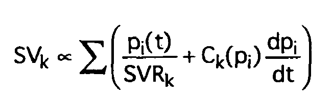
![]()
![]()
Das in der aktuellen (k-ten) Pulsperiode errechnete Herzzeitvolumen ergibt sich dann als![]()
![]()
Das Steuerprogramm im Festspeicher (ROM) kann selbstredend weitere Routinen enthalten, welche der Vorrichtung zusätzliche Funktionalitäten verleihen.The control program in the read-only memory (ROM) may of course contain further routines which give the device additional functionalities.
Über ein Display-Subsystem 18 können die Funktion p(t) dargestellt und das Herzeitvolumen PCCO sowie ggf. weitere hämodynamische Parameter ausgegeben werden.The function p (t) can be displayed via a
Selbstredend kann die Vorrichtung mit weiteren dem Fachmann an sich bekannten Komponenten ausgestattet sein, beispielsweise Massenspeichermedien zur Aufzeichnung von Rohdaten und/oder berechneten hämodynamischen Parametern. Die Recheneinheit (CPU) kann mit einem oder mehreren herkömmlichen Mikroprozessoren, ggf. unterstützt durch Coprozessoren zur Beschleunigung von Fließkommaoperationen, aber auch mit sogn. digitalen Signalprozessoren (DSP) ausgestattet sein. Entsprechende Lösungen, wie auch weitere Details der Hardware-Ausführung, können analog üblicher Pulskonturanalyse-Geräte gemäß dem Stand der Technik umgesetzt sein.Of course, the device may be equipped with further components known per se to the person skilled in the art, for example mass storage media for recording raw data and / or calculated hemodynamic parameters. The computing unit (CPU) can with one or more conventional microprocessors, possibly supported by coprocessors to accelerate floating point operations, but also with sogn. digital signal processors (DSP). Corresponding solutions, as well as further details of the hardware implementation, can be implemented analogously to conventional pulse contour analysis devices according to the prior art.
Claims (17)
- Device for determining a haemodynamic parameter of a patient by means of pulse contour analysis, having an input channel (1) for reading in a pressure signal that varies over time and at least approximately corresponds to an aortic pressure or an arterial pressure close to the aorta of a patient, as a function of the time p(t), and an evaluation unit for calculating the haemodynamic parameter using the function p(t) and the systemic resistance of the body of the patient SVR, wherein the evaluation unit is equipped to regularly recalculate the systemic resistance of the body of the patient SVR using the function p(t), characterised in that the recalculation of the systemic resistance SVR comprises determining the time constant τ of the approximately exponential pressure drop during the diastole.
- Device according to claim 1, which has memory means (RAM) for temporarily storing the pressure signal read in, at least over the pulse cycle, as a function of the time P(t).
- Device according to claim 1, wherein the recalculation of the systemic resistance is provided as the product

wherein,
SVRcal is a calibration value of the systemic resistance,
τ cal is a calibration value of the time constant τ,
Pd is the diastolic arterial pressure,
Pdcal is a calibration value of the diastolic arterial pressure, and
a, b are empirically determined or estimated exponents. - Device according to claim 3, wherein the calibration values SVRcal, τ cal and APdcal are determined in the course of a calibration measurement by means of thermodilution.
- Device according to either of claims 3-4, wherein 0.15 < a < 0.6, preferably a = 0.3.
- Device according to any one of claims 3-5, wherein 0.5 < b < 2, preferably b = 1.
- Device according to any one of the preceding claims, wherein the evaluation unit is furthermore equipped to regularly recalculate parameters of the compliance function C(p) using the function p(t).
- Device according to claim 7, wherein the recalculation of the compliance function C(p) is provided according to the formula

wherein,
(MAP - CVP) k is the difference between the mean arterial pressure and central venous pressure of the diastole of the current pulse period,
< dp/dt > k is the mean gradient of an arterial pressure curve in the diastole of the current pulse period, and
f(p) is a correction function. - Device according to claim 8, wherein the correction function has the form

with empirically determined or estimated coefficients k1, k2, k3. - Device according to claim 9, wherein k1 = 9/5, k2 = 17/25 and k3 = 9/2.
- Device according to any one of the preceding claims, wherein the haemodynamic parameter is the cardiac output CO as a product of the pulse rate HR and of the stroke volume SV.
- Device according to claim 11, wherein the calculation of the stroke volume is provided as the integral

wherein SVR is the systemic resistance. - Device according to any one of the preceding claims, wherein the evaluation unit has differentiation means to form the second derivative y" from the function p(t), as well as evaluation means to determine a site of maximum curvature of the function p(t) in a determination region between the maximum and the minimum function value of the pulse cycle as the site of the transition between the systole and diastole.
- Device according to any one of the preceding claims, having output means (18) to output the haemodynamic parameter.
- Device according to any one of the preceding claims, having connection means to connect an arterial catheter (5) suitable for the pressure measurement.
- Device according to any one of the preceding claims, having an input channel (3) to read in a pressure signal that varies over time and at least approximately corresponds to the central venous pressure of the patient.
- Device according to claim 16, furthermore having connection means to connect a central venous catheter (16) suitable for the pressure measurement.
Applications Claiming Priority (2)
| Application Number | Priority Date | Filing Date | Title |
|---|---|---|---|
| DE102004024334 | 2004-05-17 | ||
| DE102004024334A DE102004024334A1 (en) | 2004-05-17 | 2004-05-17 | Device for determining a hemodynamic parameter |
Publications (2)
| Publication Number | Publication Date |
|---|---|
| EP1598005A1 EP1598005A1 (en) | 2005-11-23 |
| EP1598005B1 true EP1598005B1 (en) | 2009-03-18 |
Family
ID=34939167
Family Applications (1)
| Application Number | Title | Priority Date | Filing Date |
|---|---|---|---|
| EP05102713A Active EP1598005B1 (en) | 2004-05-17 | 2005-04-07 | Device for determining hemodynamic parameters |
Country Status (9)
| Country | Link |
|---|---|
| US (1) | US7588542B2 (en) |
| EP (1) | EP1598005B1 (en) |
| JP (1) | JP4322227B2 (en) |
| KR (1) | KR20060046075A (en) |
| CN (1) | CN100581450C (en) |
| BR (1) | BRPI0501917A8 (en) |
| DE (2) | DE102004024334A1 (en) |
| ES (1) | ES2323179T3 (en) |
| RU (1) | RU2378982C2 (en) |
Cited By (2)
| Publication number | Priority date | Publication date | Assignee | Title |
|---|---|---|---|---|
| DE102011114666A1 (en) * | 2011-09-30 | 2013-04-04 | Pulsion Medical Systems Se | Device for hemodynamic monitoring |
| CN105640533A (en) * | 2015-12-23 | 2016-06-08 | 南昌大学 | In-vitro hemodynamic characteristic test device |
Families Citing this family (39)
| Publication number | Priority date | Publication date | Assignee | Title |
|---|---|---|---|---|
| DE102004024335A1 (en) * | 2004-05-17 | 2005-12-15 | Pulsion Medical Systems Ag | Device for determining the transition between systole and diastole |
| US7654964B1 (en) * | 2006-03-16 | 2010-02-02 | Pacesetter, Inc. | System and method for detecting arterial blood pressure based on aortic electrical resistance using an implantable medical device |
| US20070239041A1 (en) * | 2006-03-28 | 2007-10-11 | The Johns Hopkins University | Non-invasive Venous Pressure Measurement |
| EP1847218A1 (en) * | 2006-04-19 | 2007-10-24 | Pulsion Medical Systems AG | Patient monitoring apparatus for determining volume responsiveness of a monitored patient |
| US7643879B2 (en) * | 2006-08-24 | 2010-01-05 | Cardiac Pacemakers, Inc. | Integrated cardiac rhythm management system with heart valve |
| CA2711445A1 (en) * | 2007-01-17 | 2008-07-24 | Universite De Montreal | Method and system for administering an anaesthetic |
| US8551005B2 (en) * | 2007-12-13 | 2013-10-08 | Robert A. BARUCH | Monitoring respiratory variation of pulse pressure |
| EP2087836B1 (en) * | 2008-02-07 | 2012-04-04 | Pulsion Medical Systems AG | Apparatus and method for determining a physiological parameter |
| US8725260B2 (en) | 2008-02-11 | 2014-05-13 | Cardiac Pacemakers, Inc | Methods of monitoring hemodynamic status for rhythm discrimination within the heart |
| US8369960B2 (en) | 2008-02-12 | 2013-02-05 | Cardiac Pacemakers, Inc. | Systems and methods for controlling wireless signal transfers between ultrasound-enabled medical devices |
| US20110009714A1 (en) * | 2008-02-27 | 2011-01-13 | Koninklijke Philips Electronics N.V. | Hemodynamic monitors and alarms |
| DE102008026708B4 (en) * | 2008-06-04 | 2014-01-23 | Iprm Intellectual Property Rights Management Ag | Device for determining the blood volume and / or blood volume flow and method for operating the same |
| WO2010027652A1 (en) * | 2008-08-26 | 2010-03-11 | Cardiac Pacemakers, Inc. | Cardiac output estimation using pulmonary artery pressure |
| EP2347705A4 (en) * | 2008-10-01 | 2013-11-27 | Irumedi Co Ltd | Cardiovascular analysis system |
| EP2334230A1 (en) * | 2008-10-10 | 2011-06-22 | Cardiac Pacemakers, Inc. | Systems and methods for determining cardiac output using pulmonary artery pressure measurements |
| WO2010059291A1 (en) | 2008-11-19 | 2010-05-27 | Cardiac Pacemakers, Inc. | Assessment of pulmonary vascular resistance via pulmonary artery pressure |
| EP2189111A1 (en) * | 2008-11-21 | 2010-05-26 | Pulsion Medical Systems AG | Apparatus and method for determining a physiologic parameter |
| US8491487B2 (en) | 2009-02-11 | 2013-07-23 | Edwards Lifesciences Corporation | Detection of parameters in cardiac output related waveforms |
| US20180344174A9 (en) | 2009-09-23 | 2018-12-06 | Lightlab Imaging, Inc. | Lumen Morphology and Vascular Resistance Measurements Data Collection Systems, Apparatus and Methods |
| ES2660570T3 (en) * | 2009-09-23 | 2018-03-23 | Lightlab Imaging, Inc. | Systems, devices and methods of data collection of vascular resistance and luminal morphology |
| US8814800B2 (en) * | 2009-10-29 | 2014-08-26 | Cnsystems Medizintechnik Ag | Apparatus and method for enhancing and analyzing signals from a continuous non-invasive blood pressure device |
| DE102010010610A1 (en) | 2010-03-08 | 2011-09-08 | Pulsion Medical Systems Ag | Portable sensor device and patient monitor |
| WO2012009350A1 (en) * | 2010-07-12 | 2012-01-19 | Yale University | Apparatus, systems and methods analyzing pressure and volume waveforms in the vasculature |
| US20120150003A1 (en) * | 2010-12-09 | 2012-06-14 | Siemens Medical Solutions Usa, Inc. | System Non-invasive Cardiac Output Determination |
| RU2669744C2 (en) * | 2012-09-10 | 2018-10-15 | Конинклейке Филипс Н.В. | Device and method to improve dependability of physiological parameter measurements |
| CN102908134B (en) * | 2012-11-20 | 2015-03-18 | 深圳市理邦精密仪器股份有限公司 | Parameter calibration method and parameter calibration system for continuously monitoring cardiac output |
| CN104379055B (en) | 2012-12-14 | 2018-05-15 | 皇家飞利浦有限公司 | Equipment for the physiological parameter for measuring user |
| DE102013018366B4 (en) | 2013-11-02 | 2017-05-24 | Drägerwerk AG & Co. KGaA | Monitoring device for monitoring the state of a patient's circulation and computer program product for this monitoring |
| US10405757B2 (en) | 2014-02-25 | 2019-09-10 | Icu Medical, Inc. | Patient monitoring system with gatekeeper signal |
| JP6971150B2 (en) * | 2015-02-09 | 2021-11-24 | 日東電工株式会社 | Methods and devices for deriving the mean arterial pressure of a subject |
| CA3002372C (en) | 2015-10-19 | 2021-03-02 | Icu Medical, Inc. | Hemodynamic monitoring system with detachable display unit |
| DE102015120216A1 (en) * | 2015-11-23 | 2017-05-24 | B. Braun Avitum Ag | Method for calibrating a measurement signal and for tracking a quantitative quantity |
| US20180214033A1 (en) * | 2017-02-02 | 2018-08-02 | Edwards Lifesciences Corporation | Hemodynamic monitor providing enhanced cardiac output measurements |
| JP7352472B2 (en) * | 2017-06-09 | 2023-09-28 | アビオメド インコーポレイテッド | Determination of cardiac parameters to adjust blood pump support |
| FR3070250B1 (en) | 2017-08-30 | 2022-04-22 | Inria Inst Nat Rech Informatique & Automatique | HEART DEVICE |
| DE102019125062A1 (en) * | 2018-09-19 | 2020-03-19 | Redwave Medical GmbH | Method for the automated determination of hemodynamic parameters in a blood vessel on invasively recorded pulse waves |
| CN110584640B (en) * | 2019-08-13 | 2022-05-24 | 深圳邦健生物医疗设备股份有限公司 | Method, device, terminal and readable medium for monitoring heart pumping condition |
| CN113367669B (en) * | 2021-07-07 | 2022-06-14 | 湖南敬凯投资管理有限公司 | Pulse reproduction system and control method and reproduction method thereof |
| CN114937488B (en) * | 2022-04-29 | 2024-04-12 | 无锡市华焯光电科技有限公司 | Pulse data processing method, device and storage medium |
Family Cites Families (8)
| Publication number | Priority date | Publication date | Assignee | Title |
|---|---|---|---|---|
| IL77677A (en) | 1986-01-22 | 1990-04-29 | Daniel Goor | Method and apparatus for detecting mycardial ischemia |
| US4821734A (en) * | 1987-04-21 | 1989-04-18 | Nihon Seimitsu Sokki Co., Ltd. | Sphygmomanometer |
| US5423323A (en) * | 1993-08-30 | 1995-06-13 | Rocky Mountain Research, Inc. | System for calculating compliance and cardiac hemodynamic parameters |
| GB9714550D0 (en) * | 1997-07-10 | 1997-09-17 | Lidco Ltd | Improved method and apparatus for the measurement of cardiac output |
| WO1999047044A1 (en) * | 1998-03-20 | 1999-09-23 | Hypertension Diagnostics, Inc. | Sensor and method for sensing arterial pulse pressure |
| DE19814371A1 (en) * | 1998-03-31 | 1999-10-14 | Pulsion Verwaltungs Gmbh & Co | Method for in-vivo determination of the compliance function and the systemic blood flow of a living being and device for carrying out the method |
| US6315735B1 (en) | 1999-03-31 | 2001-11-13 | Pulsion Medical Systems Ag | Devices for in-vivo determination of the compliance function and the systemic blood flow of a living being |
| EP1419732A1 (en) * | 2001-03-01 | 2004-05-19 | Pulsion Medical Systems AG | Central venous catheter assembly for hemodynamic monitoring |
-
2004
- 2004-05-17 DE DE102004024334A patent/DE102004024334A1/en not_active Ceased
-
2005
- 2005-04-07 EP EP05102713A patent/EP1598005B1/en active Active
- 2005-04-07 ES ES05102713T patent/ES2323179T3/en active Active
- 2005-04-07 DE DE502005006860T patent/DE502005006860D1/en active Active
- 2005-05-16 RU RU2005114869/14A patent/RU2378982C2/en active
- 2005-05-16 CN CN200510072610A patent/CN100581450C/en active Active
- 2005-05-16 US US11/130,355 patent/US7588542B2/en active Active
- 2005-05-17 JP JP2005143563A patent/JP4322227B2/en active Active
- 2005-05-17 BR BRPI0501917A patent/BRPI0501917A8/en active Search and Examination
- 2005-05-17 KR KR1020050041114A patent/KR20060046075A/en not_active Application Discontinuation
Cited By (2)
| Publication number | Priority date | Publication date | Assignee | Title |
|---|---|---|---|---|
| DE102011114666A1 (en) * | 2011-09-30 | 2013-04-04 | Pulsion Medical Systems Se | Device for hemodynamic monitoring |
| CN105640533A (en) * | 2015-12-23 | 2016-06-08 | 南昌大学 | In-vitro hemodynamic characteristic test device |
Also Published As
| Publication number | Publication date |
|---|---|
| BRPI0501917A (en) | 2006-01-10 |
| KR20060046075A (en) | 2006-05-17 |
| CN1698534A (en) | 2005-11-23 |
| RU2378982C2 (en) | 2010-01-20 |
| JP4322227B2 (en) | 2009-08-26 |
| RU2005114869A (en) | 2006-11-27 |
| ES2323179T3 (en) | 2009-07-08 |
| JP2005329237A (en) | 2005-12-02 |
| CN100581450C (en) | 2010-01-20 |
| DE102004024334A1 (en) | 2005-12-22 |
| US7588542B2 (en) | 2009-09-15 |
| EP1598005A1 (en) | 2005-11-23 |
| US20050267379A1 (en) | 2005-12-01 |
| DE502005006860D1 (en) | 2009-04-30 |
| BRPI0501917A8 (en) | 2017-01-17 |
Similar Documents
| Publication | Publication Date | Title |
|---|---|---|
| EP1598005B1 (en) | Device for determining hemodynamic parameters | |
| DE69004833T2 (en) | Intravascular infusion monitoring device and method. | |
| EP2384138B1 (en) | Device for determining and/or monitoring fistula patency on the basis of an amplitude of the heart pressure signal during a blood treatment | |
| EP3302231B1 (en) | Method and device for ascertaining a blood pressure curve | |
| DE69205417T2 (en) | METHOD FOR DETERMINING THE STRIKE VOLUME AND THE HEART VOLUME OF THE HUMAN HEART. | |
| DE60302995T2 (en) | Blood Pressure Monitor | |
| DE102012007081B4 (en) | Method and measuring and calculating unit for long-term monitoring of the arterial vascular stiffness and vascular calcification of a patient | |
| EP1628570B1 (en) | Method for the determination of hemodynamic parameters | |
| EP2574276A1 (en) | Device for hemodynamic monitoring | |
| DE69029502T2 (en) | Electronic sphygmomanometer | |
| EP3145394B1 (en) | Method and device for determining central systolic blood pressure | |
| DE102006010813A1 (en) | Dialysis machine with measuring devices for detecting the blood pressure and methods for determining the blood pressure and a storage medium for use in a dialysis machine | |
| DE3200368A1 (en) | METHOD AND DEVICE FOR MEASURING BLOOD PRESSURE | |
| EP2908720B1 (en) | Device and method for detecting and signalling a stress state of a person | |
| DE102007057235A1 (en) | Method and device for determining the end of the systolic part of a pressure curve | |
| EP1746931B1 (en) | Device for determining the transition between systole and diastole | |
| DE102010016035A1 (en) | System and method for noninvasive blood pressure measurement | |
| DE69025095T2 (en) | Electric blood pressure monitor | |
| EP1673009A1 (en) | Blood pressure measuring method and blood pressure manometer | |
| EP3316768B1 (en) | Device and method for monitoring and measuring the autoregulation mechanism of the blood pressure in a living being | |
| DE102019125062A1 (en) | Method for the automated determination of hemodynamic parameters in a blood vessel on invasively recorded pulse waves | |
| EP0445809B1 (en) | Device for measuring blood pressure | |
| DE3786491T2 (en) | Device for deriving the minute volume of the right ventricle from temperature dilution curves of high reproduction quality. | |
| EP3557277B1 (en) | Method for monitoring movement information of a patient in a magnetic resonance device, magnetic resonance device, computer program and electronically readable data carrier | |
| DE102013017716A1 (en) | Method and device for non-invasive blood pressure measurement |
Legal Events
| Date | Code | Title | Description |
|---|---|---|---|
| PUAI | Public reference made under article 153(3) epc to a published international application that has entered the european phase |
Free format text: ORIGINAL CODE: 0009012 |
|
| AK | Designated contracting states |
Kind code of ref document: A1 Designated state(s): AT BE BG CH CY CZ DE DK EE ES FI FR GB GR HU IE IS IT LI LT LU MC NL PL PT RO SE SI SK TR |
|
| AX | Request for extension of the european patent |
Extension state: AL BA HR LV MK YU |
|
| 17P | Request for examination filed |
Effective date: 20051212 |
|
| AKX | Designation fees paid |
Designated state(s): DE ES FR GB IT |
|
| GRAP | Despatch of communication of intention to grant a patent |
Free format text: ORIGINAL CODE: EPIDOSNIGR1 |
|
| GRAS | Grant fee paid |
Free format text: ORIGINAL CODE: EPIDOSNIGR3 |
|
| GRAA | (expected) grant |
Free format text: ORIGINAL CODE: 0009210 |
|
| AK | Designated contracting states |
Kind code of ref document: B1 Designated state(s): DE ES FR GB IT |
|
| REG | Reference to a national code |
Ref country code: GB Ref legal event code: FG4D Free format text: NOT ENGLISH |
|
| REF | Corresponds to: |
Ref document number: 502005006860 Country of ref document: DE Date of ref document: 20090430 Kind code of ref document: P |
|
| REG | Reference to a national code |
Ref country code: ES Ref legal event code: FG2A Ref document number: 2323179 Country of ref document: ES Kind code of ref document: T3 |
|
| PLBE | No opposition filed within time limit |
Free format text: ORIGINAL CODE: 0009261 |
|
| STAA | Information on the status of an ep patent application or granted ep patent |
Free format text: STATUS: NO OPPOSITION FILED WITHIN TIME LIMIT |
|
| 26N | No opposition filed |
Effective date: 20091221 |
|
| PGFP | Annual fee paid to national office [announced via postgrant information from national office to epo] |
Ref country code: IT Payment date: 20140428 Year of fee payment: 10 |
|
| PG25 | Lapsed in a contracting state [announced via postgrant information from national office to epo] |
Ref country code: IT Free format text: LAPSE BECAUSE OF NON-PAYMENT OF DUE FEES Effective date: 20150407 |
|
| REG | Reference to a national code |
Ref country code: FR Ref legal event code: PLFP Year of fee payment: 12 |
|
| REG | Reference to a national code |
Ref country code: FR Ref legal event code: PLFP Year of fee payment: 13 |
|
| REG | Reference to a national code |
Ref country code: FR Ref legal event code: PLFP Year of fee payment: 14 |
|
| P01 | Opt-out of the competence of the unified patent court (upc) registered |
Effective date: 20230522 |
|
| PGFP | Annual fee paid to national office [announced via postgrant information from national office to epo] |
Ref country code: GB Payment date: 20240320 Year of fee payment: 20 |
|
| PGFP | Annual fee paid to national office [announced via postgrant information from national office to epo] |
Ref country code: FR Payment date: 20240320 Year of fee payment: 20 |
|
| PGFP | Annual fee paid to national office [announced via postgrant information from national office to epo] |
Ref country code: DE Payment date: 20240320 Year of fee payment: 20 |
|
| PGFP | Annual fee paid to national office [announced via postgrant information from national office to epo] |
Ref country code: ES Payment date: 20240502 Year of fee payment: 20 |