EP1597591B1 - Gas velocity sensor - Google Patents
Gas velocity sensor Download PDFInfo
- Publication number
- EP1597591B1 EP1597591B1 EP04713943A EP04713943A EP1597591B1 EP 1597591 B1 EP1597591 B1 EP 1597591B1 EP 04713943 A EP04713943 A EP 04713943A EP 04713943 A EP04713943 A EP 04713943A EP 1597591 B1 EP1597591 B1 EP 1597591B1
- Authority
- EP
- European Patent Office
- Prior art keywords
- interferometer
- gas
- velocity sensor
- electromagnetic radiation
- laser
- Prior art date
- Legal status (The legal status is an assumption and is not a legal conclusion. Google has not performed a legal analysis and makes no representation as to the accuracy of the status listed.)
- Expired - Lifetime
Links
- 230000005670 electromagnetic radiation Effects 0.000 claims abstract description 40
- 230000003287 optical effect Effects 0.000 claims abstract description 19
- 238000000034 method Methods 0.000 claims description 27
- 238000000926 separation method Methods 0.000 claims description 18
- 239000013078 crystal Substances 0.000 claims description 12
- 230000000694 effects Effects 0.000 claims description 6
- 230000005855 radiation Effects 0.000 claims description 6
- 229910052779 Neodymium Inorganic materials 0.000 claims description 4
- QEFYFXOXNSNQGX-UHFFFAOYSA-N neodymium atom Chemical group [Nd] QEFYFXOXNSNQGX-UHFFFAOYSA-N 0.000 claims description 4
- 230000001419 dependent effect Effects 0.000 claims description 3
- 239000007789 gas Substances 0.000 description 28
- 238000001228 spectrum Methods 0.000 description 10
- 239000000443 aerosol Substances 0.000 description 6
- 239000002245 particle Substances 0.000 description 4
- 230000005540 biological transmission Effects 0.000 description 3
- 230000008859 change Effects 0.000 description 3
- 238000005259 measurement Methods 0.000 description 3
- 125000006850 spacer group Chemical group 0.000 description 3
- 239000011248 coating agent Substances 0.000 description 2
- 238000000576 coating method Methods 0.000 description 2
- 238000001514 detection method Methods 0.000 description 2
- 238000002310 reflectometry Methods 0.000 description 2
- 230000009286 beneficial effect Effects 0.000 description 1
- 230000008901 benefit Effects 0.000 description 1
- 238000012937 correction Methods 0.000 description 1
- 230000003292 diminished effect Effects 0.000 description 1
- 238000000605 extraction Methods 0.000 description 1
- 238000007689 inspection Methods 0.000 description 1
- 230000010354 integration Effects 0.000 description 1
- 230000004048 modification Effects 0.000 description 1
- 238000012986 modification Methods 0.000 description 1
- 230000008569 process Effects 0.000 description 1
- 230000003014 reinforcing effect Effects 0.000 description 1
- 238000005070 sampling Methods 0.000 description 1
- 239000007787 solid Substances 0.000 description 1
- 230000007704 transition Effects 0.000 description 1
Images

Classifications
-
- G—PHYSICS
- G01—MEASURING; TESTING
- G01P—MEASURING LINEAR OR ANGULAR SPEED, ACCELERATION, DECELERATION, OR SHOCK; INDICATING PRESENCE, ABSENCE, OR DIRECTION, OF MOVEMENT
- G01P5/00—Measuring speed of fluids, e.g. of air stream; Measuring speed of bodies relative to fluids, e.g. of ship, of aircraft
- G01P5/26—Measuring speed of fluids, e.g. of air stream; Measuring speed of bodies relative to fluids, e.g. of ship, of aircraft by measuring the direct influence of the streaming fluid on the properties of a detecting optical wave
-
- G—PHYSICS
- G01—MEASURING; TESTING
- G01S—RADIO DIRECTION-FINDING; RADIO NAVIGATION; DETERMINING DISTANCE OR VELOCITY BY USE OF RADIO WAVES; LOCATING OR PRESENCE-DETECTING BY USE OF THE REFLECTION OR RERADIATION OF RADIO WAVES; ANALOGOUS ARRANGEMENTS USING OTHER WAVES
- G01S17/00—Systems using the reflection or reradiation of electromagnetic waves other than radio waves, e.g. lidar systems
- G01S17/02—Systems using the reflection of electromagnetic waves other than radio waves
- G01S17/50—Systems of measurement based on relative movement of target
- G01S17/58—Velocity or trajectory determination systems; Sense-of-movement determination systems
Definitions
- This invention relates to a gas velocity sensor and to a method of determining a gas velocity.
- this invention relates to an air velocity sensor that is particularly suited to use on an aircraft such that the velocity of the aircraft can be determined.
- a Pitot tube This is a small tube that projects from the front of an aircraft that measures the air pressure in the tube as the aircraft is in flight. The velocity of the aircraft relative to the air can be inferred from this air pressure using an approximate square-law relationship. This method has only limited accuracy and requires corrections to be applied for various effects such as humidity, temperature and flow disturbances that would otherwise lead to inaccurate velocity readings.
- GPS global position sensors
- this technique suffers from the requirement for long integration times to obtain adequate accuracy and also the requirement for continuous availability of GPS signals from satellites.
- this technique provides a measure of the velocity in inertial space rather than the velocity relative to the air: the difference between these velocities can be critical, e.g. around the stall speed of an aircraft flying downstream.
- the intensity of backscattered light is strongly dependent on the wavelength of the light produced by the laser and on the nature of the scattering particles.
- concentration of aerosols At low altitudes, the concentration of aerosols is at its highest and so contributes heavily to the backscattered laser light.
- concentration of aerosols varies by at least four orders of magnitude between sea level and 50,000 feet, the highest operating altitude for most aircraft. If an optical sensor of the type described above is to be adapted to operate on an aircraft, it must be able to operate at any altitude and under any weather conditions. Hence, the concentration of scattering particles must remain as constant as possible to maintain a reliable signal.
- US-A-5 394 243 is related to a device for Doppler axial wind speed, air turbulence and aerosol detection.
- the device comprises a centered optical system constituted by a single Fabry-Perot interferometer, a prism, an interference filter, and an afocal objective lens, all elements having the optical axes coinciding.
- the spectrum offset between the emitted beam and the backscattered beam as caused by the component of the speed of the target along the optical axis (Doppler effect) is measured.
- US-A-4 195 931 is related an apparatus for remote detection of the location and intensity of clear air turbulence in association with aircraft through analysis of the spectrum of scattered laser light.
- Back scattered light from a volume of air is directed into the collecting telescope by a mirror.
- a narrow band filter blocks out ambient light.
- Light from telescope and narrow band filter is passed through a Fabry-Perot interferometer which creates a circular symmetric interference pattern. Analysis of the pattern projected onto the detector through a lens permits determination of the distance of the volume of air for determining the location of the clear air turbulence.
- the present invention resides in a gas velocity sensor according to claim 1.
- the intensity of light incident on the photodetector may be monitored and the gas velocity estimated.
- the interference pattern produced by the interferometer will be in varying degrees of registry with the pattern on the spatial filter and will therefore allow varying amounts of electromagnetic radiation to pass.
- the interference pattern varies as a function of the wavelength of the electromagnetic radiation incident on the interferometer and so is a measure of the Doppler frequency of the gas and hence the velocity of the gas relative to the gas velocity sensor.
- Fabry-Perot interferometer Although it is preferred to use a Fabry-Perot interferometer, other interferometers may be employed. Essentially, any interferometer that produces an interference pattern that can be replicated on a spatial filter is appropriate.
- the spatial filter has a ring structure corresponding to the interference pattern produced by the interferometer when illuminated with electromagnetic radiation at substantially the wavelength of the electromagnetic radiation source.
- the electromagnetic radiation when the electromagnetic radiation is scattered from a moving gas, its wavelength may shift slightly about the wavelength of the electromagnetic radiation source and so is likely to be only partially diminished by mismatch between the interference pattern produced by the interferometer and the pattern on the spatial filter.
- a movable mirror is employed within a Fabry-Perot interferometer.
- Fabry-Perot interferometers contain a pair of facing mirrors that bounce electromagnetic radiation off one another. Having at least one of the mirrors movable allows the separation between the mirrors to be varied: varying their separation alters the interference pattern they produce, i.e. the rings' radii increase or decrease.
- the Fabry-Perot interferometer may further comprise an electromechanical actuator operable to move the movable mirror, such as a piezoelectric device or the like.
- the electromagnetic radiation source is operable to produce ultra-violet light.
- This is advantageous when used in air velocity sensing because scattering is dominated by air molecules at ultra-violet wavelengths. This mitigates the effect of scattering from aerosols that cause a problem due to their varying concentration with altitude.
- Ultra-violet radiation is beneficial because scattering from air molecules is governed by the Rayleigh scattering process and the scattered light intensity is proportional to ⁇ -4 , where ⁇ corresponds to the wavelength of the incident light
- the light source is a laser with a neodymium:YLF laser being particularly preferred.
- the interferometer comprises a pair of mirrors and the laser comprises a laser cavity, the separation of the mirrors being set to equal to the time taken for light to travel the length of the laser cavity times the speed of light.
- This arrangement mitigates against the fact that most lasers produce signals at closely-spaced wavelength intervals that would otherwise produce bright regions in an interference pattern with a wide range of positions that effectively become superimposed to form an interference pattern that is smeared out with no net variation in intensity.
- the mirror spacing to the effective length of the laser cavity using the time taken for light to travel the real length times the speed of light compensates for differing refractive indices of components of the laser cavity
- the bright regions produced by the interferometer coincide in the interference pattern to add constructively thereby reinforcing each other.
- the mean separation of the mirrors is matched to the effective length of the laser cavity.
- the laser cavity comprises a crystal and a Q-switch bounded at one end by an input mirror and at the other end by an output mirror. It is advantageous for the input mirror to reflect at 1.064 ⁇ m and to transmit at 810 nm.
- the output mirror is semi-reflective and wherein the gas velocity sensor further comprises a non-linear crystal and a filter arranged such that, in use, light output by the output mirror is incident firstly upon the non-linear crystal and then on the filter, wherein the filter transmits light substantially at the third harmonic and rejects light at other wavelengths.
- the gas velocity sensor further comprises a lens to collect light scattered by the gas.
- the gas velocity electromagnetic radiation further comprises another lens for producing a substantially collimated beam and/or a narrow-band filter positioned on the optical path on the input side of the interferometer.
- the narrow-band filter is configured to allow electromagnetic radiation with a wavelength substantially coincident with that of the electromagnetic radiation source to pass whilst rejecting other wavelengths. This allows extraction of the relatively weak scattered electromagnetic radiation from the otherwise overwhelming background.
- the gas velocity sensor further comprises a voltmeter operable to measure a signal produced by the photodetector.
- a gate is configured to receive a signal from the photodetector and send a signal to the voltmeter. This allows the electromagnetic radiation incident on the photodetector to be read in a selective manner. For example, a time delay may be used that corresponds to a certain time of flight from the electromagnetic radiation source to the photodetector. This is useful as the time of flight will correspond to sampling the gas at a set distance away from the gas velocity sensor.
- the gas velocity sensor may comprise a controller operable to open the gate, e.g. a pulse generator.
- the controller is operable to produce pulsed electromagnetic radiation output from the electromagnetic radiation source. This allows control of the timing interval between when a pulse of electromagnetic radiation is produced by the electromagnetic radiation source and when the photodetector is read.
- the gas velocity sensor further comprises a time delay circuit configured to receive a signal from the controller and to pass a signal to the gate. This conveniently allows a desired time of flight to be set.
- the gas velocity sensor further comprises a computer, wherein the computer is operable to apply a voltage to the actuator and/or to receive a signal from the voltmeter.
- the gas velocity sensor is an air velocity sensor installed on an aircraft.
- the present invention resides in a method of determining gas velocity according to claim 16.
- the method further comprises the step of illuminating the gas with ultra-violet light.
- the method further comprises the step of passing electromagnetic radiation collected through a lens to produce a substantially collimated beam that is passed to the interferometer.
- the substantially collimated beam may optionally be passed through a narrow-band filter prior to passing the electromagnetic radiation to the interferometer.
- the interferometer has a pair of mirrors, at least one of which is movable, the method further comprising the step of moving the mirror so that the separation between the mirrors is varied and measuring the output of the photodetector at a plurality of mirror separations.
- the step of adjusting the mirror separation is performed to obtain a maximum output from the photodetector.
- the step of adjusting the mirror separation is performed to scan the separation of the mirrors through a predetermined range.
- the method may optionally further comprise the steps of sending a voltage to an electromechanical actuator to effect movement of the mirror and recording the voltage produced by the photodetector as a function of the voltage applied to the actuator.
- the spatial filter has a structure corresponding to the interference pattern produced by the interferometer when illuminated with electromagnetic radiation at the wavelength of the electromagnetic radiation source.
- the air velocity sensor 10 comprises a laser 12 for illuminating an airstream 14, collecting optics 16 for collecting light backscattered from the airstream 14 and for transmitting light along an optical path that sees the light propagate through a Fabry-Perot interferometer 18, a spatial filter 20 and on to a photodetector 22.
- the output of the photodetector 22 is passed to a voltmeter 24 via a gate 26.
- the air velocity sensor 10 further comprises a pulse generator 28 operable to drive the laser 12 to produce pulses of light and also to drive the gate 26 of the voltmeter 24.
- the laser 12 generates pulses of ultra-violet light in a narrow collimated beam 30 that is reflected by a small plane mirror 32 to form a reflected beam 34 that propagates into a flowing airstream 14 where it is scattered.
- the choice of an ultra-violet laser 12 means that the wavelength of the light 30, 34 is such that scattering is predominantly from air molecules rather than any aerosols in the airstream 14.
- a proportion of the light backscattered 36 along the direction of the reflected beam is collected by the collecting optics 16 prior to transmission to the Fabry-Perot interferometer 18.
- the collecting optics 16 comprise a first lens 38 that collects the backscattered light 36 prior to the light being focused into an approximately collimated beam 40 by a second lens 42.
- the collimated beam 40 passes through a narrow-band filter 44 that transmits light at or close to the ultra-violet wavelength of the laser 12 but rejects all other wavelengths that arise from ambient light from the sky entering the first lens 38. This narrow-band filter 44 thus removes the dominant ambient light to leave the much weaker backscattered light 36 that subsequently propagates to the Fabry-Perot interferometer 18.
- the Fabry-Perot interferometer 18 is shown in more detail in Figure 2 .
- the filtered beam enters the Fabry-Perot interferometer 18 through a semi-reflective mirror 46.
- the Fabry-Perot interferometer 18 comprises a second semi-reflective mirror 48: the semi-reflective mirrors 46, 48 are separated by spacers 50 such that mirror surfaces 46a, 48a are parallel to an accuracy much smaller than the wavelength of the ultra-violet laser light 30, 34 and are separated by a distance d.
- Two spacers 50 are shown in Figure 2 , but more may be used to improve the parallelism of the semi-reflective mirrors 46, 48.
- a beam of light incident on the Fabry-Perot interferometer 18 reflects successively from the semi-reflective mirrors 46, 48 such that interference results.
- the interference pattern produced is seen in light emerging from the second semi-reflective mirror 48.
- the emergent light 52 varies in intensity by an amount related to the angle ⁇ (measured with respect to the normal between the semi-reflective mirrors 46, 48, as shown in Figure 2 ) and to its wavelength ⁇ .
- the interference pattern 54 produced by the ultra-violet light of the laser 12 is shown in Figure 3 : this interference pattern 54 comprises a set of concentric rings 56 that can be seen in the light emerging from the Fabry-Perot interferometer 18 when it has been focused to the focal plane of a third lens 58.
- a spatial filter 20 is placed at the focal plane of lens 58.
- the spatial filter 20 is an opaque surface containing concentric transparent apertures that correspond to the regions of bright light 56 in Figure 3 . Accordingly, the interference pattern 54 produced by the Fabry-Perot interferometer 18 when illuminated by the ultra-violet light from the laser 12 passes through the spatial filter 20 undiminished and is incident upon the photodetector 22.
- the photodetector 22 produces a signal 60 that is proportional to the light intensity incident thereon.
- This photodetector signal 60 is read by the voltmeter 24 when allowed to pass through the gate 26.
- the gate 26 is activated by a signal 62 passed by the pulse generator 28.
- the pulse generator 28 produces a regular sequence of pulses 62 that trigger the emission of ultra-violet light from the laser 12 and operate the gate 26 to the voltmeter 24 after a suitable time delay set by the fixed time delay circuit 64. In operation, pulses from the pulse generator 28 trigger output of pulsed light from the laser 12.
- Light backscattered 36 by the flowing airstream 14 enters the photodetector 22 after a delay corresponding to the time of flight through the path between the laser 12 and the photodetector 22.
- setting the time delay at 64 to a particular value enables the voltmeter 24 to measure light backscattered from a region in the flowing airstream 14 a predetermined distance away from the air velocity sensor 10.
- the backscattered light 36 will have the frequency f 0 of the laser 12. However, if the airstream 14 is flowing, the backscattered light 36 will be subject to a Doppler shift to a new frequency f slightly away from the laser frequency f 0 . This results in the concentric rings 56 in the interference pattern 54 produced by the Fabry-Perot interferometer 18 shifting to slightly different radii, thereby creating a mismatch with the spatial filter 20. This mismatch produces a drop in the light intensity transmitted to the photodetector 22 and hence read by the voltmeter 24. The level of voltage drop is proportional to the shift in frequency which is in turn proportional to the velocity of the flowing airstream 14.
- the above method and apparatus produces a measure of the velocity of a flowing airstream 14 in the direction of the reflected beam 34.
- a modification to this method and apparatus is preferred in order to give more accurate results.
- a scanning Fabry-Perot interferometer 18 Rather than using a Fabry-Perot interferometer 18 that has a fixed separation between the semi-reflective mirrors 46, 48, it is preferred to use a scanning Fabry-Perot interferometer 18.
- the separation of the semi-reflective mirrors 56, 58 is varied about a mean separation d by applying a uniform force to the periphery of one of the semi-reflective mirrors 56 via a number of electromechanical actuators 66 (e.g. piezoelectric devices).
- the spacers 50 have semi-elastic properties such that when force is applied to the semi-reflective mirror 56 by the actuators 66, the spacing d changes by a distance greater than half the wavelength of the light 30, 34 from the laser 12. Varying the spacing d causes the concentric rings 56 in the interference pattern 54 produced by the Fabry-Perot interferometer 18 to change in position, as can be inferred by inspection of equation (3).
- interference patterns 54 can be produced with concentric rings 56 that scan across the spatial filter 20 such that at a particular value the concentric rings 56 of the interference pattern 54 will be in registry with the transparent rings 56 of the spatial filter 20 and a maximum voltage will be read by the voltmeter 24.
- the change in the ring radius caused by the Doppler shift in frequency can be compensated by an equal and opposite shift due to the voltage applied to the actuators 66.
- a computer 68 produces a digital output 70 that is converted to an analogue voltage 72 by a digital-to-analogue converter 74.
- the analogue voltage 72 is applied to the actuators 66, thereby effecting scans of the Fabry-Perot interferometer 18.
- the voltage 76 produced by the voltmeter 24 is digitised by an analogue-to-digital converter 78 before being passed to the computer 68.
- the computer 68 records the measured voltage 76 against the voltage applied 72 to the actuators 66 in order to produce a plot of light intensity against Fabry-Perot interferometer 18 setting.
- the computer 68 determines the frequency of the backscattered light 36 corresponding to the peak in the plot, taking into account the known characteristics of the Fabry-Perot interferometer 18 and other optical components of the air velocity sensor 10 (these can be found from calibration).
- the air velocity sensor 10 described above works on the assumption that the laser 12 produces a stable output on a single optical mode of the laser cavity such that the laser frequency spectrum covers a narrow band corresponding approximately to the Fourier spectrum of the pulse shape. This is necessary so that the spectrum of frequencies detected corresponds largely to the spectrum of Doppler shifts caused by scattering from the airstream 14 (and modified by the characteristics of the Fabry-Perot interferometer 18) with only a small contribution from the spectrum of the laser 12.
- Pulsed lasers that can operate in this way do so on the basis of seeded Q-swit--hing.
- This arrangement uses a Q-switched solid state laser that normally operates on a number of axial modes of the laser cavity simultaneously. This leads to light produced simultaneously at a number of frequencies corresponding to the different axial modes.
- a second laser is employed to operate continuously at a low power (typically only a few milliwatts) but only on a single mode of the laser, thereby producing an output laser beam having a very narrow frequency spectrum.
- Such devices employ frequency-selective optical elements in the laser cavity to ensure operation in one mode only, but this can only be achieved for low powers.
- the output from this continuously-operating laser is passed into the cavity of the Q-switched laser and is tuned to a frequency close to one of the axial modes of the Q-swifiched laser cavity.
- the output of the continuous laser is known as the seed power.
- the Q-switch When the Q-switch operates, the laser produces output pulses but only on the cavity mode matched in frequency to the seed laser. Accordingly, the output pulses have the desired narrow frequency spectrum.
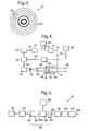
- Figure 5 shows a diode-pumped neodymium:YLF laser 12'.
- This laser 12' is operated at the third harmonic of the 1.064 ⁇ m laser transition to produce ultra-violet light 30 with a wavelength of 355 nm. This produces a large amount of Rayleigh backscatter from air molecules at all operational altitudes.
- the laser 12' comprises a neodymium:YLF crystal 80 with a high reflectivity coating 82 forming a mirror at one end.
- This coating 82 is optimised to reflect most strongly around 1.064 ⁇ m.
- a partially-reflective concave output mirror 84 is provided a short distance from the non-coated end of the crystal 80a, with an electro-optic Q-switch 86 interposed therebetween.
- the two mirrors 82, 84 are aligned to produce a laser cavity 88 on the axis of the crystal 80. It is convenient to make the overall length of the laser cavity 88 as short as possible so that the laser pulses are of a short duration (a few nanoseconds) with high peak power.
- the laser 12' is pumped by a continuous high power laser diode array 90 operating to produce light of a wavelength of approximately 810 nm that is focused by a lens system 92 into the crystal 80 through the end mirror 82.
- the end mirror 82 is designed to have a high transmission at 810 nm in addition to being optimised to reflect at 1.064 ⁇ m.
- the Q-switch 86 is operated by a regular sequence of short electrical pulses supplied by a pulse generator 94 causing the laser 12' to generate pulses of light at approximately 1.064 ⁇ m.
- the pulses typically have a peak power of several kilowatts and a pulse repetition frequency of 10,000 to 50,000 pulses per second.
- the beam 96 that emerges from the partially-reflective mirror 84 is focused by a lens 98 into a non-linear crystal 100 that produces the second and third harmonics of the input wavelength.
- a filter 102 is used to select the third harmonic at 355 nm, whilst discarding the other wavelengths.
- a pulsed beam 104 with a mean power of about 100 mW is produced with a narrow frequency spectrum centred on a wavelength of 355 nm.
- the pulses 104 have a pulse repetition frequency to match that of the pulse generator 94, a pulse duration of a few nanoseconds and a peak power of about 1 kW. These pulses 104 are passed to the plane mirror to be reflected so as to illuminate the flowing airstream 14.
- Each of the frequencies will produce its own interference pattern 54 of concentric rings 56 and these will combine to form a pattern in the plane of the spatial filter 20 that has no regular ring patterns. Accordingly, there will be no frequency-dependent variation in light intensity incident on the photodetector 22 resulting from scanning of the Fabry-Perot interferometer 18.
- the present invention is not restricted to application in aircraft only, but can be employed in any situation where a determination of the velocity of a gas is required.
- the ground-based sensor that measures air-velocities in the atmosphere described in the introduction could benefit from many features of the present invention.
- the present invention is not restricted to a measurement of air velocities but can be used to measure the velocity of any number of gases.
- backscattering from the gas is required so the wavelength of the light used to illuminate the gas is best adjusted for optimal scattering strength. Where a gas does not scatter light strongly, particles may be introduced into the gas flow that do scatter light strongly.
- the adjustable Fabry-Perot interferometer 18 embodiment described above merely scans the spacing d of the Fabry-Perot interferometer 18 to identify the Doppler shift of the backscattered light 36.
- an active feedback loop could be used such that the computer 68 controls the spacing d of the semi-reflective mirrors 46, 48 to ensure a peak light intensity is measured by the voltmeter 24.
- the computer 68 may systematically increase or decrease the spacing d of the semi-reflective mirrors 46, 48 to maximise the voltage read by the voltmeter 24.
- the frequency of the backscattered light 36, and hence the velocity of the airstream 14 can then be inferred from the voltage set on the actuators 66 that produces the peak voltmeter reading.
- a feedback loop may be used such that the output of the voltmeter 24 is maintained at a constant level that is a fixed fraction of the peak value. Maintaining a voltage equal to one half of the peak voltage has been found to be advantageous because plotting a graph of the voltage produced by the voltmeter 24 against Doppler shift produces a curve with a maximum gradient around half the peak voltage. Operating in this region of high gradient means enhanced accuracy of measurement.
- This mode of operation may be implemented as follows.
- the computer 68 produces a sequence of voltage step increments 72 for the actuators 66 thereby altering the spacing of the mirrors 46, 48 by stepped increments.
- the voltmeter's output 76 is measured by the computer 68 as a function of the drive voltage set on the actuators 66 to plot a curve of light intensity as a function of Doppler frequency.
- the computer 68 identifies the peak value of the curve and adjusts the mirror spacing d until the voltmeter signal 76 is equal to one half of the peak value.
- the computer 68 then continually adjusts the voltage 72 passed to the actuators to maintain the same value on the voltmeter signal 76.
- the voltage 72 is proportional to the Doppler shift in frequency and hence the air velocity, and hence the computer 68 can determine the air velocity.
- the computer 68 is programmed to resample the peak voltmeter signal 76 periodically. This is because the intensity of backscattered light 36 passing through the air velocity sensor 10 slowly changes due partly to changes in the output power of the laser 12 and partly due to changes in air density (e.g. because of a change in altitude).
- the embodiment of Figure 5 uses a second pulse generator 94 to operate the Q-switch 86.
- the other pulse generator 28 could uf course be used to operate the Q-switch 86 through its signal 62 in addition to operating the gate 26, thereby removing the need for a second pulse generator.
- the computer 68 could fulfil the role of the pulse generators 28, 94, i.e. the computer 68 could be used to generate the pulsed timing signal 62.
Landscapes
- Physics & Mathematics (AREA)
- Engineering & Computer Science (AREA)
- Electromagnetism (AREA)
- General Physics & Mathematics (AREA)
- Computer Networks & Wireless Communication (AREA)
- Radar, Positioning & Navigation (AREA)
- Remote Sensing (AREA)
- Multimedia (AREA)
- Aviation & Aerospace Engineering (AREA)
- Investigating Or Analysing Materials By Optical Means (AREA)
- Optical Radar Systems And Details Thereof (AREA)
- Investigating Or Analyzing Materials By The Use Of Fluid Adsorption Or Reactions (AREA)
Applications Claiming Priority (3)
| Application Number | Priority Date | Filing Date | Title |
|---|---|---|---|
| GBGB0304344.5A GB0304344D0 (en) | 2003-02-26 | 2003-02-26 | Gas velocity sensor |
| GB0304344 | 2003-02-26 | ||
| PCT/GB2004/000714 WO2004077067A1 (en) | 2003-02-26 | 2004-02-24 | Gas velocity sensor |
Publications (2)
| Publication Number | Publication Date |
|---|---|
| EP1597591A1 EP1597591A1 (en) | 2005-11-23 |
| EP1597591B1 true EP1597591B1 (en) | 2008-08-20 |
Family
ID=9953669
Family Applications (1)
| Application Number | Title | Priority Date | Filing Date |
|---|---|---|---|
| EP04713943A Expired - Lifetime EP1597591B1 (en) | 2003-02-26 | 2004-02-24 | Gas velocity sensor |
Country Status (8)
| Country | Link |
|---|---|
| US (1) | US7301610B2 (enExample) |
| EP (1) | EP1597591B1 (enExample) |
| JP (1) | JP4540604B2 (enExample) |
| AT (1) | ATE405843T1 (enExample) |
| DE (1) | DE602004015939D1 (enExample) |
| ES (1) | ES2310285T3 (enExample) |
| GB (1) | GB0304344D0 (enExample) |
| WO (1) | WO2004077067A1 (enExample) |
Families Citing this family (13)
| Publication number | Priority date | Publication date | Assignee | Title |
|---|---|---|---|---|
| US7564539B2 (en) * | 2002-08-02 | 2009-07-21 | Ophir Corporation | Optical air data systems and methods |
| US8072584B2 (en) * | 2002-08-02 | 2011-12-06 | Ophir Corporation | Optical air data systems and methods |
| ATE361472T1 (de) | 2002-08-02 | 2007-05-15 | Ophir Corp | System und verfahren zum optischen messen von luftdaten |
| JP5332103B2 (ja) * | 2004-09-15 | 2013-11-06 | 三菱電機株式会社 | 光波レーダ装置 |
| US8227735B1 (en) * | 2007-07-24 | 2012-07-24 | Lockheed Martin Coherent Technologies, Inc. | Combined active and passive imaging system with radiation source unit and detector |
| WO2009034370A1 (en) * | 2007-09-11 | 2009-03-19 | Bae Systems Plc | Gas velocity sensor |
| DE102008031681A1 (de) * | 2008-07-04 | 2010-01-14 | Eads Deutschland Gmbh | LIDAR-Verfahren zur Messung von Geschwindigkeiten und LIDAR-Vorrichtung mit zeitgesteuerter Detektion |
| ITMI20090400A1 (it) * | 2009-03-16 | 2010-09-17 | Datamed Srl | Metodo di misurazione della velocita' di un fluido e relativa apparecchiatura. |
| US8797550B2 (en) | 2009-04-21 | 2014-08-05 | Michigan Aerospace Corporation | Atmospheric measurement system |
| WO2011016892A2 (en) * | 2009-05-15 | 2011-02-10 | Michigan Aerospace Corporation | Range imaging lidar |
| US10598769B2 (en) | 2013-05-06 | 2020-03-24 | Danmarks Tekniske Universitet | Coaxial direct-detection LIDAR-system |
| US9933514B1 (en) * | 2015-03-12 | 2018-04-03 | The Boeing Company | LADAR systems with dynamic receiver filters |
| FR3150871B1 (fr) | 2023-07-07 | 2025-06-20 | Office National Detudes Rech Aerospatiales | Systeme lidar a detection directe |
Family Cites Families (13)
| Publication number | Priority date | Publication date | Assignee | Title |
|---|---|---|---|---|
| US4195931A (en) * | 1978-05-18 | 1980-04-01 | The United States Of America As Represented By The Secretary Of The Army | Clear air turbulence detector |
| DE2841499C2 (de) * | 1978-09-23 | 1984-04-12 | Messerschmitt-Bölkow-Blohm GmbH, 8000 München | Laser-Luftwerte-Sensor |
| US4400975A (en) * | 1981-05-27 | 1983-08-30 | Atlantic Richfield Company | Apparatus for monitoring liquid flow rates |
| EP0227911A3 (en) | 1981-12-08 | 1988-08-24 | Lockheed Corporation | Optical air data measurement system |
| US4818101A (en) * | 1986-12-02 | 1989-04-04 | The Boeing Company | Laser-doppler velocimetry |
| FR2648915B1 (fr) * | 1989-06-26 | 1991-09-27 | Centre Nat Rech Scient | Dispositif de mesure de la vitesse du vent a moyenne altitude |
| FR2659452B1 (fr) * | 1990-03-08 | 1992-07-03 | Sextant Avionique | Systeme a laser, de mesure de l'angle d'incidence d'un aeronef. |
| FR2688592B1 (fr) * | 1992-03-16 | 1994-06-10 | Seso | Dispositif de mesure de vitesse axiale de gaz. |
| US5317376A (en) * | 1992-12-03 | 1994-05-31 | Litton Systems, Inc. | Solid state pulsed coherent laser radar for short range velocimetry applications |
| KR960701362A (ko) * | 1993-03-05 | 1996-02-24 | 알 더블유 벡크함 | 가스 검출 장치(Gas detection devices) |
| US5642194A (en) * | 1996-02-05 | 1997-06-24 | The Regents Of The University Of California | White light velocity interferometer |
| FR2750215B1 (fr) * | 1996-06-25 | 1998-09-11 | Sextant Avionique | Sonde velocimetrique optique |
| US6313908B1 (en) * | 1998-07-02 | 2001-11-06 | The United States Of America As Represented By The Administrator Of The National Aeronautics And Space Administration | Apparatus and method using a holographic optical element for converting a spectral distribution to image points |
-
2003
- 2003-02-26 GB GBGB0304344.5A patent/GB0304344D0/en not_active Ceased
-
2004
- 2004-02-24 DE DE602004015939T patent/DE602004015939D1/de not_active Expired - Lifetime
- 2004-02-24 WO PCT/GB2004/000714 patent/WO2004077067A1/en not_active Ceased
- 2004-02-24 JP JP2005501717A patent/JP4540604B2/ja not_active Expired - Fee Related
- 2004-02-24 ES ES04713943T patent/ES2310285T3/es not_active Expired - Lifetime
- 2004-02-24 US US10/490,863 patent/US7301610B2/en not_active Expired - Lifetime
- 2004-02-24 AT AT04713943T patent/ATE405843T1/de not_active IP Right Cessation
- 2004-02-24 EP EP04713943A patent/EP1597591B1/en not_active Expired - Lifetime
Also Published As
| Publication number | Publication date |
|---|---|
| ATE405843T1 (de) | 2008-09-15 |
| JP2006512584A (ja) | 2006-04-13 |
| DE602004015939D1 (de) | 2008-10-02 |
| US7301610B2 (en) | 2007-11-27 |
| JP4540604B2 (ja) | 2010-09-08 |
| EP1597591A1 (en) | 2005-11-23 |
| US20040263826A1 (en) | 2004-12-30 |
| WO2004077067A1 (en) | 2004-09-10 |
| GB0304344D0 (en) | 2003-04-02 |
| ES2310285T3 (es) | 2009-01-01 |
Similar Documents
| Publication | Publication Date | Title |
|---|---|---|
| EP1597591B1 (en) | Gas velocity sensor | |
| US7518736B2 (en) | Optical air data system | |
| US7463341B2 (en) | Method and apparatus for detecting wind velocities by means of a doppler-lidar system | |
| EP2705350B1 (en) | Remote measurement of shallow depths in semi-transparent media | |
| US20110188029A1 (en) | Direct detection doppler lidar method and direction detection doppler lidar device | |
| US4995720A (en) | Pulsed coherent Doppler laser radar | |
| US20100163733A1 (en) | Airborne tunable mid-ir laser gas-correlation sensor | |
| US7705971B2 (en) | System and method for determining crosswinds | |
| US6813020B2 (en) | Device for determining the values of at least one parameter of particles, especially of water droplets | |
| EP2191281B1 (en) | Gas velocity sensor | |
| CA2108961A1 (en) | Spectrocopic imaging system with ultrasonic detection of absorption of modulated electromagnetic radiation | |
| US5313263A (en) | System for, and method of, determining the speed of an airborne vehicle | |
| US7450222B1 (en) | Correlated-intensity velocimeter for arbitrary reflector | |
| US7616294B2 (en) | Laser anemometry with improved eye safety | |
| US5285260A (en) | Spectroscopic imaging system with ultrasonic detection of absorption of modulated electromagnetic radiation | |
| EP2679984A1 (en) | Method and arrangement for carrying out time-domain measurements | |
| US8896836B1 (en) | Fluid properties measurements using wavelength modulation spectroscopy with first harmonic detection | |
| EP2333564A1 (fr) | Sonde anémométrique bi-statique asservie | |
| GB2075787A (en) | Measuring velocity by doppler shift of laser radiation | |
| Wise | A Microresonator-Based Laser Doppler Velocity Sensor For Interplanetary Atmospheric Re-Entry | |
| Salameh et al. | Flow Speed Sensor Based on Optical Microresonators | |
| Schall | Recent Developments In Laser Doppler Anemometry At The German-French Research Institute Saint-Louis (ISL) | |
| Rahm et al. | Airborne cw Doppler lidar (ADOLAR) | |
| Köpp | Doppler Lidar for Atmospheric Remote Sensing and Aircraft Safety Operations | |
| Morbieu et al. | Airspeed Measurement With A CO [sub] 2 [/sub] Lidar |
Legal Events
| Date | Code | Title | Description |
|---|---|---|---|
| PUAI | Public reference made under article 153(3) epc to a published international application that has entered the european phase |
Free format text: ORIGINAL CODE: 0009012 |
|
| 17P | Request for examination filed |
Effective date: 20050915 |
|
| AK | Designated contracting states |
Kind code of ref document: A1 Designated state(s): AT BE BG CH CY CZ DE DK EE ES FI FR GB GR HU IE IT LI LU MC NL PT RO SE SI SK TR |
|
| AX | Request for extension of the european patent |
Extension state: AL LT LV MK |
|
| DAX | Request for extension of the european patent (deleted) | ||
| GRAP | Despatch of communication of intention to grant a patent |
Free format text: ORIGINAL CODE: EPIDOSNIGR1 |
|
| GRAS | Grant fee paid |
Free format text: ORIGINAL CODE: EPIDOSNIGR3 |
|
| GRAA | (expected) grant |
Free format text: ORIGINAL CODE: 0009210 |
|
| AK | Designated contracting states |
Kind code of ref document: B1 Designated state(s): AT BE BG CH CY CZ DE DK EE ES FI FR GB GR HU IE IT LI LU MC NL PT RO SE SI SK TR |
|
| REG | Reference to a national code |
Ref country code: GB Ref legal event code: FG4D |
|
| REG | Reference to a national code |
Ref country code: CH Ref legal event code: EP |
|
| REG | Reference to a national code |
Ref country code: IE Ref legal event code: FG4D |
|
| REF | Corresponds to: |
Ref document number: 602004015939 Country of ref document: DE Date of ref document: 20081002 Kind code of ref document: P |
|
| REG | Reference to a national code |
Ref country code: SE Ref legal event code: TRGR |
|
| REG | Reference to a national code |
Ref country code: ES Ref legal event code: FG2A Ref document number: 2310285 Country of ref document: ES Kind code of ref document: T3 |
|
| PG25 | Lapsed in a contracting state [announced via postgrant information from national office to epo] |
Ref country code: NL Free format text: LAPSE BECAUSE OF FAILURE TO SUBMIT A TRANSLATION OF THE DESCRIPTION OR TO PAY THE FEE WITHIN THE PRESCRIBED TIME-LIMIT Effective date: 20080820 |
|
| PG25 | Lapsed in a contracting state [announced via postgrant information from national office to epo] |
Ref country code: SI Free format text: LAPSE BECAUSE OF FAILURE TO SUBMIT A TRANSLATION OF THE DESCRIPTION OR TO PAY THE FEE WITHIN THE PRESCRIBED TIME-LIMIT Effective date: 20080820 Ref country code: FI Free format text: LAPSE BECAUSE OF FAILURE TO SUBMIT A TRANSLATION OF THE DESCRIPTION OR TO PAY THE FEE WITHIN THE PRESCRIBED TIME-LIMIT Effective date: 20080820 Ref country code: AT Free format text: LAPSE BECAUSE OF FAILURE TO SUBMIT A TRANSLATION OF THE DESCRIPTION OR TO PAY THE FEE WITHIN THE PRESCRIBED TIME-LIMIT Effective date: 20080820 |
|
| PG25 | Lapsed in a contracting state [announced via postgrant information from national office to epo] |
Ref country code: BE Free format text: LAPSE BECAUSE OF FAILURE TO SUBMIT A TRANSLATION OF THE DESCRIPTION OR TO PAY THE FEE WITHIN THE PRESCRIBED TIME-LIMIT Effective date: 20080820 |
|
| PG25 | Lapsed in a contracting state [announced via postgrant information from national office to epo] |
Ref country code: BG Free format text: LAPSE BECAUSE OF FAILURE TO SUBMIT A TRANSLATION OF THE DESCRIPTION OR TO PAY THE FEE WITHIN THE PRESCRIBED TIME-LIMIT Effective date: 20081120 Ref country code: DK Free format text: LAPSE BECAUSE OF FAILURE TO SUBMIT A TRANSLATION OF THE DESCRIPTION OR TO PAY THE FEE WITHIN THE PRESCRIBED TIME-LIMIT Effective date: 20080820 |
|
| PG25 | Lapsed in a contracting state [announced via postgrant information from national office to epo] |
Ref country code: RO Free format text: LAPSE BECAUSE OF FAILURE TO SUBMIT A TRANSLATION OF THE DESCRIPTION OR TO PAY THE FEE WITHIN THE PRESCRIBED TIME-LIMIT Effective date: 20080820 Ref country code: SK Free format text: LAPSE BECAUSE OF FAILURE TO SUBMIT A TRANSLATION OF THE DESCRIPTION OR TO PAY THE FEE WITHIN THE PRESCRIBED TIME-LIMIT Effective date: 20080820 Ref country code: CZ Free format text: LAPSE BECAUSE OF FAILURE TO SUBMIT A TRANSLATION OF THE DESCRIPTION OR TO PAY THE FEE WITHIN THE PRESCRIBED TIME-LIMIT Effective date: 20080820 Ref country code: PT Free format text: LAPSE BECAUSE OF FAILURE TO SUBMIT A TRANSLATION OF THE DESCRIPTION OR TO PAY THE FEE WITHIN THE PRESCRIBED TIME-LIMIT Effective date: 20090120 |
|
| PLBE | No opposition filed within time limit |
Free format text: ORIGINAL CODE: 0009261 |
|
| STAA | Information on the status of an ep patent application or granted ep patent |
Free format text: STATUS: NO OPPOSITION FILED WITHIN TIME LIMIT |
|
| 26N | No opposition filed |
Effective date: 20090525 |
|
| PG25 | Lapsed in a contracting state [announced via postgrant information from national office to epo] |
Ref country code: EE Free format text: LAPSE BECAUSE OF FAILURE TO SUBMIT A TRANSLATION OF THE DESCRIPTION OR TO PAY THE FEE WITHIN THE PRESCRIBED TIME-LIMIT Effective date: 20080820 |
|
| PG25 | Lapsed in a contracting state [announced via postgrant information from national office to epo] |
Ref country code: MC Free format text: LAPSE BECAUSE OF NON-PAYMENT OF DUE FEES Effective date: 20090228 |
|
| REG | Reference to a national code |
Ref country code: CH Ref legal event code: PL |
|
| EUG | Se: european patent has lapsed | ||
| PG25 | Lapsed in a contracting state [announced via postgrant information from national office to epo] |
Ref country code: CH Free format text: LAPSE BECAUSE OF NON-PAYMENT OF DUE FEES Effective date: 20090228 Ref country code: LI Free format text: LAPSE BECAUSE OF NON-PAYMENT OF DUE FEES Effective date: 20090228 |
|
| REG | Reference to a national code |
Ref country code: IE Ref legal event code: MM4A |
|
| REG | Reference to a national code |
Ref country code: FR Ref legal event code: ST Effective date: 20091030 |
|
| PG25 | Lapsed in a contracting state [announced via postgrant information from national office to epo] |
Ref country code: IE Free format text: LAPSE BECAUSE OF NON-PAYMENT OF DUE FEES Effective date: 20090224 |
|
| REG | Reference to a national code |
Ref country code: FR Ref legal event code: RN |
|
| PG25 | Lapsed in a contracting state [announced via postgrant information from national office to epo] |
Ref country code: FR Free format text: LAPSE BECAUSE OF NON-PAYMENT OF DUE FEES Effective date: 20090302 |
|
| REG | Reference to a national code |
Ref country code: FR Ref legal event code: FC |
|
| REG | Reference to a national code |
Ref country code: FR Ref legal event code: FC |
|
| PG25 | Lapsed in a contracting state [announced via postgrant information from national office to epo] |
Ref country code: GR Free format text: LAPSE BECAUSE OF FAILURE TO SUBMIT A TRANSLATION OF THE DESCRIPTION OR TO PAY THE FEE WITHIN THE PRESCRIBED TIME-LIMIT Effective date: 20081121 |
|
| PGRI | Patent reinstated in contracting state [announced from national office to epo] |
Ref country code: FR Effective date: 20100929 |
|
| PG25 | Lapsed in a contracting state [announced via postgrant information from national office to epo] |
Ref country code: IT Free format text: LAPSE BECAUSE OF NON-PAYMENT OF DUE FEES Effective date: 20090224 |
|
| PG25 | Lapsed in a contracting state [announced via postgrant information from national office to epo] |
Ref country code: LU Free format text: LAPSE BECAUSE OF NON-PAYMENT OF DUE FEES Effective date: 20090224 |
|
| PG25 | Lapsed in a contracting state [announced via postgrant information from national office to epo] |
Ref country code: SE Free format text: LAPSE BECAUSE OF NON-PAYMENT OF DUE FEES Effective date: 20090225 |
|
| PG25 | Lapsed in a contracting state [announced via postgrant information from national office to epo] |
Ref country code: HU Free format text: LAPSE BECAUSE OF FAILURE TO SUBMIT A TRANSLATION OF THE DESCRIPTION OR TO PAY THE FEE WITHIN THE PRESCRIBED TIME-LIMIT Effective date: 20090221 |
|
| PGFP | Annual fee paid to national office [announced via postgrant information from national office to epo] |
Ref country code: IT Payment date: 20100215 Year of fee payment: 6 |
|
| PGRI | Patent reinstated in contracting state [announced from national office to epo] |
Ref country code: IT Effective date: 20110616 |
|
| PG25 | Lapsed in a contracting state [announced via postgrant information from national office to epo] |
Ref country code: TR Free format text: LAPSE BECAUSE OF FAILURE TO SUBMIT A TRANSLATION OF THE DESCRIPTION OR TO PAY THE FEE WITHIN THE PRESCRIBED TIME-LIMIT Effective date: 20080820 |
|
| PG25 | Lapsed in a contracting state [announced via postgrant information from national office to epo] |
Ref country code: CY Free format text: LAPSE BECAUSE OF FAILURE TO SUBMIT A TRANSLATION OF THE DESCRIPTION OR TO PAY THE FEE WITHIN THE PRESCRIBED TIME-LIMIT Effective date: 20080820 |
|
| PGRI | Patent reinstated in contracting state [announced from national office to epo] |
Ref country code: SE Effective date: 20100420 |
|
| PGRI | Patent reinstated in contracting state [announced from national office to epo] |
Ref country code: IT Effective date: 20110616 |
|
| REG | Reference to a national code |
Ref country code: FR Ref legal event code: PLFP Year of fee payment: 13 |
|
| REG | Reference to a national code |
Ref country code: FR Ref legal event code: PLFP Year of fee payment: 14 |
|
| REG | Reference to a national code |
Ref country code: FR Ref legal event code: PLFP Year of fee payment: 15 |
|
| PGFP | Annual fee paid to national office [announced via postgrant information from national office to epo] |
Ref country code: ES Payment date: 20200323 Year of fee payment: 17 |
|
| PGFP | Annual fee paid to national office [announced via postgrant information from national office to epo] |
Ref country code: FR Payment date: 20210223 Year of fee payment: 18 |
|
| PGFP | Annual fee paid to national office [announced via postgrant information from national office to epo] |
Ref country code: DE Payment date: 20210225 Year of fee payment: 18 Ref country code: SE Payment date: 20210219 Year of fee payment: 18 |
|
| REG | Reference to a national code |
Ref country code: ES Ref legal event code: FD2A Effective date: 20220513 |
|
| PG25 | Lapsed in a contracting state [announced via postgrant information from national office to epo] |
Ref country code: ES Free format text: LAPSE BECAUSE OF NON-PAYMENT OF DUE FEES Effective date: 20210225 |
|
| REG | Reference to a national code |
Ref country code: DE Ref legal event code: R119 Ref document number: 602004015939 Country of ref document: DE |
|
| REG | Reference to a national code |
Ref country code: SE Ref legal event code: EUG |
|
| PG25 | Lapsed in a contracting state [announced via postgrant information from national office to epo] |
Ref country code: SE Free format text: LAPSE BECAUSE OF NON-PAYMENT OF DUE FEES Effective date: 20220225 |
|
| PG25 | Lapsed in a contracting state [announced via postgrant information from national office to epo] |
Ref country code: FR Free format text: LAPSE BECAUSE OF NON-PAYMENT OF DUE FEES Effective date: 20220228 |
|
| PG25 | Lapsed in a contracting state [announced via postgrant information from national office to epo] |
Ref country code: DE Free format text: LAPSE BECAUSE OF NON-PAYMENT OF DUE FEES Effective date: 20220901 |
|
| PGFP | Annual fee paid to national office [announced via postgrant information from national office to epo] |
Ref country code: GB Payment date: 20230121 Year of fee payment: 20 |
|
| REG | Reference to a national code |
Ref country code: GB Ref legal event code: PE20 Expiry date: 20240223 |
|
| PG25 | Lapsed in a contracting state [announced via postgrant information from national office to epo] |
Ref country code: GB Free format text: LAPSE BECAUSE OF EXPIRATION OF PROTECTION Effective date: 20240223 |