EP1597548B1 - Method for determining optimum grating parameters for producing a diffraction grating for a vuv spectrometer - Google Patents
Method for determining optimum grating parameters for producing a diffraction grating for a vuv spectrometer Download PDFInfo
- Publication number
- EP1597548B1 EP1597548B1 EP04703091.1A EP04703091A EP1597548B1 EP 1597548 B1 EP1597548 B1 EP 1597548B1 EP 04703091 A EP04703091 A EP 04703091A EP 1597548 B1 EP1597548 B1 EP 1597548B1
- Authority
- EP
- European Patent Office
- Prior art keywords
- grating
- toroidal
- detector
- holographic
- origin
- Prior art date
- Legal status (The legal status is an assumption and is not a legal conclusion. Google has not performed a legal analysis and makes no representation as to the accuracy of the status listed.)
- Expired - Lifetime
Links
- 238000000034 method Methods 0.000 title claims description 34
- 239000000758 substrate Substances 0.000 claims description 29
- 238000005286 illumination Methods 0.000 claims description 27
- 230000005855 radiation Effects 0.000 claims description 20
- 238000004519 manufacturing process Methods 0.000 claims description 13
- 238000005259 measurement Methods 0.000 claims description 6
- 238000004590 computer program Methods 0.000 claims 2
- 210000002381 plasma Anatomy 0.000 description 22
- 238000013461 design Methods 0.000 description 17
- 230000003595 spectral effect Effects 0.000 description 13
- 230000003287 optical effect Effects 0.000 description 12
- 238000005516 engineering process Methods 0.000 description 10
- 230000004075 alteration Effects 0.000 description 9
- 230000004927 fusion Effects 0.000 description 8
- 238000011161 development Methods 0.000 description 7
- 230000018109 developmental process Effects 0.000 description 7
- 238000002474 experimental method Methods 0.000 description 6
- 239000000243 solution Substances 0.000 description 6
- 230000005540 biological transmission Effects 0.000 description 5
- 238000002310 reflectometry Methods 0.000 description 5
- 238000004364 calculation method Methods 0.000 description 4
- 239000000356 contaminant Substances 0.000 description 4
- 238000001514 detection method Methods 0.000 description 4
- 238000003384 imaging method Methods 0.000 description 4
- 150000002500 ions Chemical class 0.000 description 4
- 238000009304 pastoral farming Methods 0.000 description 4
- 238000001228 spectrum Methods 0.000 description 4
- 238000001072 vacuum ultraviolet spectrophotometry Methods 0.000 description 4
- 230000001419 dependent effect Effects 0.000 description 3
- 238000010586 diagram Methods 0.000 description 3
- 238000009826 distribution Methods 0.000 description 3
- 229910052739 hydrogen Inorganic materials 0.000 description 3
- 239000001257 hydrogen Substances 0.000 description 3
- 238000009434 installation Methods 0.000 description 3
- 241001136792 Alle Species 0.000 description 2
- UFHFLCQGNIYNRP-UHFFFAOYSA-N Hydrogen Chemical compound [H][H] UFHFLCQGNIYNRP-UHFFFAOYSA-N 0.000 description 2
- 238000004458 analytical method Methods 0.000 description 2
- 201000009310 astigmatism Diseases 0.000 description 2
- 238000011109 contamination Methods 0.000 description 2
- 230000007423 decrease Effects 0.000 description 2
- 239000012535 impurity Substances 0.000 description 2
- 238000005457 optimization Methods 0.000 description 2
- 239000002245 particle Substances 0.000 description 2
- BASFCYQUMIYNBI-UHFFFAOYSA-N platinum Chemical compound [Pt] BASFCYQUMIYNBI-UHFFFAOYSA-N 0.000 description 2
- 239000007787 solid Substances 0.000 description 2
- OAICVXFJPJFONN-UHFFFAOYSA-N Phosphorus Chemical compound [P] OAICVXFJPJFONN-UHFFFAOYSA-N 0.000 description 1
- 238000010521 absorption reaction Methods 0.000 description 1
- 230000002411 adverse Effects 0.000 description 1
- 238000003491 array Methods 0.000 description 1
- 238000003339 best practice Methods 0.000 description 1
- 229910052729 chemical element Inorganic materials 0.000 description 1
- 239000011248 coating agent Substances 0.000 description 1
- 238000000576 coating method Methods 0.000 description 1
- 238000010276 construction Methods 0.000 description 1
- 238000001816 cooling Methods 0.000 description 1
- 238000000354 decomposition reaction Methods 0.000 description 1
- 229910003460 diamond Inorganic materials 0.000 description 1
- 239000010432 diamond Substances 0.000 description 1
- 230000009977 dual effect Effects 0.000 description 1
- 239000003574 free electron Substances 0.000 description 1
- 239000000446 fuel Substances 0.000 description 1
- 238000007429 general method Methods 0.000 description 1
- PCHJSUWPFVWCPO-UHFFFAOYSA-N gold Chemical compound [Au] PCHJSUWPFVWCPO-UHFFFAOYSA-N 0.000 description 1
- 239000010931 gold Substances 0.000 description 1
- 229910052737 gold Inorganic materials 0.000 description 1
- -1 hydrogen ions Chemical class 0.000 description 1
- 238000011835 investigation Methods 0.000 description 1
- 238000002955 isolation Methods 0.000 description 1
- 239000000463 material Substances 0.000 description 1
- 238000012634 optical imaging Methods 0.000 description 1
- 230000035515 penetration Effects 0.000 description 1
- 238000000053 physical method Methods 0.000 description 1
- 229910052697 platinum Inorganic materials 0.000 description 1
- 230000008092 positive effect Effects 0.000 description 1
- 230000035945 sensitivity Effects 0.000 description 1
- 238000004611 spectroscopical analysis Methods 0.000 description 1
- 238000000992 sputter etching Methods 0.000 description 1
- 230000001052 transient effect Effects 0.000 description 1
Images

Classifications
-
- G—PHYSICS
- G02—OPTICS
- G02B—OPTICAL ELEMENTS, SYSTEMS OR APPARATUS
- G02B5/00—Optical elements other than lenses
- G02B5/18—Diffraction gratings
- G02B5/1847—Manufacturing methods
- G02B5/1857—Manufacturing methods using exposure or etching means, e.g. holography, photolithography, exposure to electron or ion beams
-
- G—PHYSICS
- G01—MEASURING; TESTING
- G01J—MEASUREMENT OF INTENSITY, VELOCITY, SPECTRAL CONTENT, POLARISATION, PHASE OR PULSE CHARACTERISTICS OF INFRARED, VISIBLE OR ULTRAVIOLET LIGHT; COLORIMETRY; RADIATION PYROMETRY
- G01J3/00—Spectrometry; Spectrophotometry; Monochromators; Measuring colours
- G01J3/12—Generating the spectrum; Monochromators
- G01J3/18—Generating the spectrum; Monochromators using diffraction elements, e.g. grating
-
- Y—GENERAL TAGGING OF NEW TECHNOLOGICAL DEVELOPMENTS; GENERAL TAGGING OF CROSS-SECTIONAL TECHNOLOGIES SPANNING OVER SEVERAL SECTIONS OF THE IPC; TECHNICAL SUBJECTS COVERED BY FORMER USPC CROSS-REFERENCE ART COLLECTIONS [XRACs] AND DIGESTS
- Y10—TECHNICAL SUBJECTS COVERED BY FORMER USPC
- Y10S—TECHNICAL SUBJECTS COVERED BY FORMER USPC CROSS-REFERENCE ART COLLECTIONS [XRACs] AND DIGESTS
- Y10S359/00—Optical: systems and elements
- Y10S359/90—Methods
Definitions
- the invention relates to a method for determining the optimum grating parameters for a holographic diffraction grating, in particular for a diffraction grating for a VUV spectrometer with a planar detector.
- MCP detectors have finite spatial resolution, ie. H. Each primary-side single-electron event leads at the detector output to a light spot of finite size, which has approximately a spatial intensity distribution in the form of a Gaussian bell of the width of about 50-80 ⁇ m.
- the object of the invention is achieved on the one hand by a method for the determination of lattice parameters for the holographic production of a toroidal diffraction grating according to the main claim.
- the object of the invention is further achieved by a method for producing a diffraction grating according to the subsidiary claims, whose production parameters are determined by the aforementioned method.
- Advantageous embodiments, both of the method and of the diffraction grating can be found in the correspondingly dependent claims again.
Description
Die Erfindung betrifft ein Verfahren zur Bestimmung der optimalen Gitterparameter für ein holographisches Beugungsgitter, insbesondere für ein Beugungsgitter für ein VUV-Spektrometer mit einem ebenen Detektor.The invention relates to a method for determining the optimum grating parameters for a holographic diffraction grating, in particular for a diffraction grating for a VUV spectrometer with a planar detector.
Alle Elemente und ihre (nicht vollständig ionisierten) Ionen können anhand ihrer charakteristischen Linienstrahlung eindeutig identifiziert und unterschieden werden. Zur Messung dieser Strahlung verwendet man heute üblicherweise Spektrometer, die die Strahlung durch Beugung an einem Beugungsgitter spektral zerlegen und die auf einem Detektor abgebildeten Spektren (Intensität als Funktion der Wellenlänge) aufzeichnen.All elements and their (not fully ionized) ions can be uniquely identified and distinguished by their characteristic line radiation. Today, spectrometers are used to measure this radiation, which spectrally disperse the radiation by diffraction on a diffraction grating and record the spectra (intensity as a function of wavelength) imaged on a detector.
Die intensivsten Resonanzlinien der meisten Elemente und praktisch aller Ionen liegen im Vakuum-Ultravioletten Wellenlängenbereich (VUV, etwa 1 nm bis etwa 200 nm). Die Strahlung wird in diesem Wellenlängenbereich von Materie absorbiert, ferner nimmt die Reflektivität aller Materialien in diesem Bereich mit der Wellenlänge stark ab. Deshalb müssen Spektrometer im VUV-Bereich unter Vakuum betrieben werden und müssen mit nur einem einzigen optischen Bauteil auskommen, um eine ausreichende Transmission/Effizienz zum Nachweis der Strahlung zu gewährleisten. Die Entwicklung der Detektortechnik (MCP- Detektoren, lineare Arrays oder CCD-Chips) gibt zudem vor, dass das aufzuzeichnende Spektrum auf einer ebenen Fläche einer Größe von typischerweise 25-40 mm Breite scharf abgebildet werden muss.The most intense resonance lines of most elements and virtually all ions are in the vacuum ultraviolet wavelength range (VUV, about 1 nm to about 200 nm). The radiation is absorbed in this wavelength range of matter, also decreases the reflectivity of all materials in this area with the wavelength sharply. Therefore, spectrometers must be in the VUV range be operated under vacuum and have to make do with only a single optical component, in order to ensure sufficient transmission / efficiency to detect the radiation. The development of detector technology (MCP detectors, linear arrays or CCD chips) also states that the spectrum to be recorded must be sharply imaged on a flat surface of a size typically 25-40 mm wide.
VUV-Spektrometer bestehen daher heute üblicherweise aus den drei optischen Elementen Eintrittsspalt (ein länglicher Schlitz mit zwei scharfen und präzisen Kanten im Abstand von einigen 10 µm), abbildendes Beugungsgitter und (ebener) Detektor. Für die zweifache Aufgabenstellung der spektralen Zerlegung sowie der optischen Abbildung auf den Detektor gelangen Beugungsgitter als Reflexionsgitter mit konkaven oder toroidalen Oberflächen zum Einsatz. Zur Herstellung dieser Gitter gibt es zwei bewährte Verfahren:
- A) Mechanisches Einritzen der Gitterstriche in das Substrat mittels einer Diamant-Spitze.
- B) Holographische Beleuchtung einer dünnen Schicht eines Photo-Resists auf dem Substrat mittels Laserlicht von zwei Punkten aus. Die Gitterstriche entstehen als Interferenzmuster auf dem Substrat und werden nach der Belichtung nasschemisch sowie durch Ionen-Ätztechnik weiter ausgearbeitet.
- A) Mechanical scoring of the grating lines in the substrate by means of a diamond tip.
- B) Holographic illumination of a thin layer of a photo-resist on the substrate by means of laser light from two points. The grating lines arise as an interference pattern on the substrate and are processed wet-chemically and by ion etching after exposure.
Bei der Verwendung von abbildenden Beugungsgittern im VUV-Bereich treten Abbildungsfehler auf, d. h. ein Punkt im Eintrittsspalt wird durch das Gitter auf ein mehr oder weniger großes Gebiet (und nicht auf einen Punkt) am Detektor abgebildet. Hierdurch verschlechtern sich das Auflösungsvermögen und die Effizienz des Spektrometers. Der Stand der Technik hierzu ist wie folgt:
Bis etwa zum Jahre 1970 konnten Gitter nur nach Methode A) und mit konkaven Substraten hergestellt werden, mit geraden und parallelen Gitterstrichen (klassisches Rowland-Gitter). Dies führt z. B. zu Spektrometerkonfigurationen, bei denen das Spektrum entlang eines Kreises (auf dem "Rowland-Kreis ") entsteht. Die Verwendung ebener Detektoren führt daher zu Unschärfen in der Abbildung. Ferner treten erhebliche Lichtverluste (typischer Faktor 2-10) durch den Astigmatismus der Abbildung auf. Geritzte Gitter haben außerdem einen hohen Level an Streulicht wegen der nicht perfekt gleichmäßig ausgebildeten Gitterstriche. Zur Beschreibung eines Rowland-Gitters genügt die Angabe zweier Zahlen: Der Krümmungsradius des Substrates und die "Gitterkonstante" (Anzahl der Striche pro mm).When using imaging diffraction gratings in the VUV range aberrations occur, ie a point in the entrance slit is on through the grid on more or less large area (and not to a point) imaged on the detector. This degrades the resolution and efficiency of the spectrometer. The state of the art for this is as follows:
Until around 1970, grids could only be produced by method A) and with concave substrates, with straight and parallel grating lines (classical Rowland grating). This leads z. For example, to spectrometer configurations in which the spectrum is created along a circle (on the "Rowland circle"). The use of planar detectors therefore leads to blurring in the image. Furthermore, significant light losses (typical factor 2-10) occur due to the astigmatism of the image. Scratched grids also have a high level of stray light because of the not perfectly uniform grating lines. To describe a Rowland grating, it is sufficient to specify two numbers: the radius of curvature of the substrate and the "lattice constant" (number of lines per mm).
Seit etwa 1970 wird zunehmend Technik B) verwendet. Ein Verfahren zur Herstellung von Beugungsgittern ist beispielsweise aus
Verschiedene Konzepte zur Minimierung der Abbildungsfehler wurden seit etwa 1970 entwickelt und z. B. als "type 1" bis "type 4" aberration-corrected bezeichnet (Firma Jobin- Yvon). Die Methode kann bei konkaven und toroidalen Substraten angewendet werden. Der Streulicht-Level ist gering. Ein solches korrigiertes Gitter kann jedoch nur für eine bestimmte Spektrometerkonfiguration (Abstände, Winkel, Wellenlängenbereich) verwendet werden.Various concepts for minimizing the aberrations have been developed since about 1970 and z. B. as "
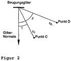
Ein holographisches Gitter wird in der Regel durch 7 Zahlenwerte (holographische Gitterparameter) beschrieben: Die beiden Krümmungsradien des Substrates ρ und R, die verwendete Laserwellenlänge λL und je 2 Koordinaten zur Beschreibung der Lage der beiden Lichtpunkte (z. B. Abstände rC, rD und Einfallswinkel γ und δ).A holographic lattice is usually described by 7 numerical values (holographic lattice parameters): the two radii of curvature of the substrate ρ and R, the laser wavelength λ L used and 2 coordinates each to describe the position of the two light points (eg distances r C , r D and angle of incidence γ and δ ).
In den 80er Jahren wurden Versuche mit computergesteuerten Ritzmaschinen durchgeführt, bei denen mechanisch geritzte Gitter mit gekrümmten Gitterstrichen variablen Abstands hergestellt wurden. Diese Technik hat sich jedoch, bedingt durch hohe Kosten sowie das Streulichtproblem dieser Gitter, nicht durchgesetzt.In the 1980's, computer-controlled scoring machines were used to produce mechanically scribed grids with variable pitch, curved grids. However, this technique has not enforced due to high cost and the stray light problem of these grids.
Da die VUV-Spektroskopie technisch aufwendig ist und nur bei speziellen Fragestellungen eingesetzt wird, gibt es folglich weltweit nur eine kleine Anzahl von Firmen, die auf dem Gebiet arbeiten, ferner gibt es nur eine sehr begrenzte Anzahl von standardmäßig lieferbaren Gittern und Spektrometern sowie einen ebenfalls sehr begrenzten Markt an Sonderentwicklungen.Since VUV spectroscopy is technically complex and used only for specific issues, there are consequently only a small number of companies operating in the field worldwide, and there are only a very limited number of standard grids and spectrometers available, as well as one very limited market of special developments.
Die Technologie zur Herstellung holographischer Gitter ist bei mindestens zwei Firmen (Jobin-Yvon und Zeiss) vorhanden. Für die Detektion der Strahlung bei Spektrometern im VUV-Bereich werden heute meist offene MCP-Detektoren eingesetzt. Diese wandeln die VUV-Photonen in freie Elektronen um, verstärken diese und wandeln die Elektronenpulse schließlich an einem Phosphor-Screen in sichtbares Licht um, welches dann mit einem geeigneten Kamerasystem aufgezeichnet werden kann. MCP-Detektoren verfügen über eine endliche Ortsauflösung, d. h. jedes primärseitige Einzelelektronenereignis führt am Detektorausgang zu einem Lichtfleck endlicher Größe, der näherungsweise eine räumliche Intensitätsverteilung in Form einer Gauss-Glocke der Breite von etwa 50-80 µm hat.The technology for producing holographic gratings is available from at least two companies (Jobin-Yvon and Zeiss). For the detection of radiation in spectrometers in the VUV range today mostly open MCP detectors are used. These convert the VUV photons into free electrons, amplify them and finally convert the electron pulses on a phosphor screen into visible light, which can then be recorded with a suitable camera system. MCP detectors have finite spatial resolution, ie. H. Each primary-side single-electron event leads at the detector output to a light spot of finite size, which has approximately a spatial intensity distribution in the form of a Gaussian bell of the width of about 50-80 μm.
Neuere Präzisionsmessungen zu den MCP-Eigenschaften, die im Rahmen der Entwicklung von spektroskopischen Instrumenten für Satelliten durchgeführt wurden, erlauben jetzt eine weitergehende Optimierung der Effizienz des Gesamtsystems VUV-Spektrometer. Hierzu wird der Einbauwinkel der MCP im Spektrometer so gewählt, dass der lokale Einfallswinkel der VUV-Strahlung auf die MCP-Oberfläche gerade im Maximum der winkelabhängigen Nachweiseffizienz des Detektors liegt. Lage und Einbauwinkel des Detektors gehören zu den Spektrometerparametern und müssen als Eingangsgrößen bei der Bestimmung des Gitterdesigns berücksichtigt werden.Recent precision measurements of the MCP properties made in the development of satellite spectroscopic instruments now allow further optimization of the overall system VUV spectrometer efficiency. For this purpose, the installation angle of the MCP in the spectrometer is selected so that the local angle of incidence of the VUV radiation on the MCP surface is just at the maximum of the angle-dependent detection efficiency of the detector. Location and installation angle of the detector belong to the spectrometer parameters and must be taken into account as input variables in the determination of the grid design.
Die VUV-Spektrometer sollen eine hohe Effizienz aufweisen, um Untersuchungen mit hoher Zeitauflösung zu ermöglichen, gleichzeitig aber eine gute Wellenlängenauflösung besitzen, damit viele Spektrallinien gleichzeitig isoliert beobachtet werden können. Die Effizienz ergibt sich aus dem Produkt aus effektiver Etendue und Gittereffizienz (dies ist der Bruchteil des einfallenden Lichts, der in die erste Beugungsordnung abgelenkt wird). Die effektive Etendue ist das Produkt dreier Größen: Ausgeleuchtete Fläche des Eintrittsspalts; ausgeleuchteter Raumwinkel; Anteil der vom Gitter kommenden Strahlen, die den Detektor innerhalb seiner sensitiven Fläche treffen.The VUV spectrometers are said to be highly efficient to enable high-time-resolution studies, but at the same time have good wavelength resolution, so that many spectral lines can be observed simultaneously in isolation. Efficiency results from the product of effective etendue and lattice efficiency (this is the fraction of incident light that is deflected into the first diffraction order). The effective etendue is the product of three sizes: illuminated area of the entrance slit; illuminated solid angle; Proportion of rays coming from the grating that hit the detector within its sensitive area.
Technische Anwendung findet die VUV-Spektroskopie im Rahmen von Fusionsexperimenten. Auf dem Weg zur kommerziellen Nutzung der Kernfusion werden weltweit Experimente mit magnetisch eingeschlossenen Wasserstoffplasmen durchgeführt, mit dem Ziel, das Produkt aus Teilchendichte, Temperatur und Einschlusszeit zu maximieren. In diesen heißen Plasmen mit Dichten oberhalb von 1019 m-3 und Temperaturen im Bereich von einigen keV treten stets neben den Wasserstoffisotopen auch andere Elemente (Plasmaverunreinigungen) mit Konzentrationen im Promille- oder Prozent-Bereich auf, die z. B. als Wandbestandteile durch den unvermeidlichen Plasma-Wand-Kontakt freigesetzt werden und ins Plasma gelangen. Die Plasmaverunreinigungen können die Plasmaeigenschaften wesentlich beeinflussen: Einerseits verdrängen sie die Wasserstoffionen aus dem (quasineutralen) Plasma und "verdünnen" damit den "Fusionsbrennstoff", andererseits strahlen sie große Leistungsdichten ab und führen so zu einer Abkühlung des Plasmas, welche im Plasmazentrum unerwünscht ist, jedoch am Plasmarand zu positiven Effekten (z. B. gleichmäßigere Leistungsauskopplung) führen kann. Für die Optimierung des Fusionsplasmas ist daher eine genaue Kenntnis des Verunreinigungsgehaltes im Plasma sowie des Transportverhaltens der Plasmaverunreinigungen erforderlich.Technical application finds the VUV spectroscopy in the context of fusion experiments. On the way to the commercial use of nuclear fusion, experiments are being conducted worldwide with magnetically confined hydrogen plasmas, with the aim of maximizing the product of particle density, temperature and entrapment time. In these hot plasmas with densities above 10 19 m -3 and temperatures in the range of a few keV always occur in addition to the hydrogen isotopes other elements (plasma contaminants) with concentrations in the per thousand or per cent range, the z. B. be released as wall components by the inevitable plasma-wall contact and enter the plasma. The Plasma impurities can significantly influence the plasma properties: On the one hand they displace the hydrogen ions from the (quasineutralen) plasma and thus "dilute" the "fusion fuel", on the other hand they emit high power densities and lead to a cooling of the plasma, which is undesirable in the plasma center, however at plasma rim can lead to positive effects (eg more even power decoupling). For the optimization of the fusion plasma, therefore, a precise knowledge of the contamination content in the plasma and the transport behavior of the plasma contaminants is required.
Eine wichtige Diagnostik zur Identifizierung der Plasmaverunreinigungen ist die Spektroskopie, denn alle chemischen Elemente und ihre (nicht vollständig ionisierten) Ionen können anhand ihrer charakteristischen Linienstrahlung eindeutig unterschieden werden. Unter den oben genannten Plasmabedingungen an magnetisch eingeschlossenen Fusionsplasmen liegen die intensivsten Resonanzlinien der meisten Elemente und praktisch aller Ionen im vakuumultravioletten Wellenlängenbereich (VUV, etwa 1 nm bis etwa 200 nm). Um alle relevanten Plasmaverunreinigungen sicher erkennen zu können, ist eine permanente und umfassende Beobachtung eines großen Wellenlängenbereiches mit guter Wellenlängenauflösung erforderlich, um möglichst viele verschiedene Spektrallinien gleichzeitig messen und unterscheiden zu können.An important diagnostic tool for the identification of plasma contaminants is spectroscopy, since all chemical elements and their (not fully ionized) ions can be clearly distinguished by their characteristic line radiation. Under the abovementioned plasma conditions on magnetically confined fusion plasmas, the most intense resonance lines of most elements and virtually all ions are in the vacuum ultraviolet wavelength range (VUV, about 1 nm to about 200 nm). In order to reliably detect all relevant plasma impurities, a permanent and comprehensive observation of a large wavelength range with good wavelength resolution is required in order to be able to measure and distinguish as many different spectral lines as possible simultaneously.
Zur Bestimmung des Transportverhaltens der Plasmaverunreinigungen werden üblicherweise transiente Experimente durchgeführt, bei denen ein zeitlich kurzer Puls einer Plasmaverunreinigung zusätzlich ins Plasma eingebracht wird und das Vordringen der Teilchen vom Plasmarand zum Plasmazentrum spektroskopisch beobachtet wird. Für solche Untersuchungen werden Spektrometer benötigt, die eine hohe Zeitauflösung aufweisen. Dies stellt einerseits Anforderungen an die Detektortechnik, andererseits werden effiziente Spektrometer benötigt, welche eine genügende Anzahl von Photonen pro Spektrallinie und pro Zeitschritt erfassen und somit eine ausreichende Messgenauigkeit (abhängig von Zahl der erfassten Photonen, z. B. Poisson-Statistik) erreichen.To determine the transport behavior of the plasma contaminants, transient experiments are usually carried out in which a temporally short pulse of plasma contamination is additionally introduced into the plasma and the penetration of the particles from the plasma edge to the plasma center is observed spectroscopically. For such investigations spectrometers are required, which have a high time resolution. On the one hand, this makes demands on the detector technology, on the other hand, efficient spectrometers are needed which detect a sufficient number of photons per spectral line and per time step and thus achieve a sufficient measuring accuracy (depending on the number of detected photons, eg Poisson statistics).
In "
In "
S. Singh beschreibt in "
In "
Aufgabe der Erfindung ist es, ein holographisches Beugungsgitter zu schaffen, welches in einem VUV-Spektrometer mit einem ebenen Detektor eingesetzt, für einen vorgegebenen Wellenlängenbereich, insbesondere von 2,5 nm bis 160 nm, eine minimale Linienbreite am Detektor bei hoher Etendue erzielt.The object of the invention is to provide a holographic diffraction grating, which is used in a VUV spectrometer with a planar detector, for a given wavelength range, in particular from 2.5 nm to 160 nm, achieved a minimum line width at the detector at high Etendue.
Die Aufgabe der Erfindung wird einerseits gelöst durch ein Verfahren zur Bestimmung von Gitterparametern für die holographische Herstellung eines toroidalen Beugungsgitters gemäß Hauptanspruch. Die Aufgabe der Erfindung wird weiter durch ein Verfahren zur Herstellung eines Beugungsgitter gemäß den Nebenansprüchen gelöst, dessen Herstellungsparameter durch das vorgenannte Verfahren ermittelt werden. Vorteilhafte Ausführungsformen, sowohl des Verfahrens als auch des Beugungsgitters finden sich in den entsprechend rückbezogenen Ansprüchen wieder.The object of the invention is achieved on the one hand by a method for the determination of lattice parameters for the holographic production of a toroidal diffraction grating according to the main claim. The object of the invention is further achieved by a method for producing a diffraction grating according to the subsidiary claims, whose production parameters are determined by the aforementioned method. Advantageous embodiments, both of the method and of the diffraction grating can be found in the correspondingly dependent claims again.
Gegenstand der Erfindung ist insbesondere ein Verfahren zur Ermittlung und Bestimmung von Gitterparametern, mit dessen Hilfe vorteilhafte Beugungsgitter für ein VUV-Spektrometer mit einem ebenen Detektor und vorgegebenen Spektrometerparametern hergestellt werden können, die gegenüber dem Stand der Technik deutlich verbesserte, insbesondere minimale Linienbreiten am Detektor bei einer hohen Etendue aufweisen.The invention particularly relates to a method for determining and determining lattice parameters, with the aid of which advantageous diffraction gratings for a VUV spectrometer with a planar detector and predetermined spectrometer parameters can be produced, which compared to the prior art significantly improved, in particular minimum linewidths at the detector have a high etendue.
Es wurde im Rahmen der Erfindung gefunden, dass zur Lösung der Aufgabe die mittlere Linienbreite der 11Spektrallinien" auf der Detektorebene zu minimieren ist. Die Variablen, bezüglich derer das Minimum gesucht wird, sind die folgenden sieben Gitterparameter: Kleiner und großer Radius des toroidalen Gittersubstrates, die Abstände der holographischen Beleuchtungspunkte vom Gitterursprung, die Winkelstellung der holographischen Beleuchtungspunkte zur Gitternormalen und die vorgegebenen Laserwellenlänge für die holographische Beleuchtung. Als Randbedingungen werden sogenannte Spektrometerparameter,wie beispielsweise Abmessungen des Eintrittsspaltes und des Detektors, Abstände des Eintrittsspaltes und des Detektors vom Gittermittelpunkt, Ein- und Ausfallswinkel der Strahlung zur Gitternormalen und der zu untersuchende Wellenlängenbereich zunächst vorgegeben. Diese werden im weiteren Verfahren jedoch innerhalb entsprechender Bandbreiten, die sich aus mechanischen und/oder physikalischen Gegebenheiten herleiten lassen, ebenfalls leicht variiert.It has been found within the scope of the invention that to solve the problem, the mean linewidth of the 11 spectral lines is to be minimized at the detector level The variables with respect to which the minimum is sought are the following seven lattice parameters: Small and large radius of the toroidal lattice substrate The distances between the holographic illumination points from the grating origin, the angular position of the holographic illumination points to the grating normal and the predetermined laser wavelength for the holographic illumination are constrained as so-called spectrometer parameters, such as dimensions of the entrance slit and the detector, distances of the entrance slit and the detector from the grating center, Ein and the angle of reflection of the radiation to the lattice normal and the wavelength range to be examined are initially specified, but these are in the further process within appropriate bandwidths, which consist of mechanical and / or physical can be deduced depending on the circumstances, also varies slightly.
Zur Lösung der Aufgabe, für einen vorgegebenen Wellenlängenbereich, welcher in der Regel durch eine physikalische Messaufgabe bestimmt ist, ein VUV-Spektrometer mit MCP-Detektor zu schaffen, ist zunächst das Design des Beugungsgitters-Spektrometers zur Verfügung zu stellen, das für einen bestimmten Wellenlängenbereich eine minimale Linienbreite bei gleichzeitig maximaler Gesamteffizienz erreicht. Die benötigte Gesamteffizienz ergibt sich beispielsweise aus der erwarteten Strahlungsintensität des Messobjektes Fusionsplasma und der angestrebten Messgenauigkeit.To solve the problem, for a given wavelength range, which is usually by a physical To provide a VUV spectrometer with MCP detector is to provide the design of the diffraction grating spectrometer first, which achieves a minimum line width for a certain wavelength range with maximum overall efficiency. The required overall efficiency results, for example, from the expected radiation intensity of the measurement object fusion plasma and the desired measurement accuracy.
Die zu lösenden Teilaufgaben sind erstens die Bestimmung eines optimalen Gitterdesigns, zweitens die Bestimmung der optimalen Winkelstellung des Detektors und drittens die Bestimmung der zugehörigen Gesamtanordnung (Spektrometerparameter). Da die zweite Teilaufgabe von der Lösung der ersten und dritten abhängt, wird die Gesamtaufgabe iterativ gelöst.The subtasks to be solved are first the determination of an optimal grid design, secondly the determination of the optimal angular position of the detector and thirdly the determination of the associated overall arrangement (spectrometer parameters). Since the second subtask depends on the solution of the first and third, the overall task is solved iteratively.
- I) Einerseits sollte die Strichdichte des Beugungsgitters einen Wert von 2000-2500 pro mm nicht überschreiten, da dies bislang die technische Grenze des Herstellungsprozesses ist. Andererseits sollte ein Wert von einigen hundert auch nicht unterschritten werden, da andernfalls die physikalischen Grenzen des Beugungsvorgangs erreicht werden.I) On the one hand, the line density of the diffraction grating should not exceed a value of 2000-2500 per mm, since this is the technical limit of the manufacturing process so far. On the other hand, a value of a few hundred should not be undershot, otherwise the physical limits of the diffraction process will be reached.
-
II) Es gibt mehrere Randbedingungen für die Wahl des Einfallswinkels α der Strahlung auf das Beugungsgitter:
- Die Reflektivität der Gitteroberfläche und damit die Beugungseffizienz des Gitters sind winkel- und wellenlängenabhängig. Die untere Grenzwellenlänge, unterhalb derer die Reflektivität verschwindet und völlige Absorption auftritt, ist etwa proportional zum Cosinus des Einfallswinkels α zur Gitternormalen:
λGrenz ≈ λP x cos (α) mit λP ≈ 15 nm für Gold oder Platin.
Zur Erzielung einer ausreichend großen Reflektivität am unteren Rand des gewählten Wellenlängenbereiches muss praktisch ein Einfallswinkel gewählt werden, dessen zugehörige Grenzwellenlänge mindestens einen Faktor 2,5 kleiner als die minimale Wellenlänge λmin des Spektrometers ist. - Gleichzeitig nimmt aber die Etendue und damit die Effizienz des Spektrometers bei streifendem Lichteinfall (wachsendem Winkel α) ab, ebenfalls etwa proportional zum Cosinus des Einfalls-Winkels zur Gitternormalen. Aufgrund von Bedingung a) und b) werden für die hier beschriebenen Spektrometer Einfallswinkel gewählt, für die die Bedingung

- Einfallswinkel von mehr als 87 Grad führen zu extremen Krümmungsradien des Gittersubstrates und damit nachteilig zu vermehrten Abbildungsfehlern und wachsendem Streulicht. Dieser Winkelbereich wird daher von vorn herein ausgeschlossen. Damit ergibt sich insbesondere, dass der sinnvolle Anwendungsbereich dieses Spektrometerkonzepts auf Wellenlängen oberhalb von etwa 2 nm beschränkt ist.
- The reflectivity of the grating surface and thus the diffraction efficiency of the grating are dependent on angle and wavelength. The lower limit wavelength, below which the reflectivity disappears and complete absorption occurs, is approximately proportional to the cosine of the angle of incidence α to the lattice normal:
λ limit ≈ λ P x cos (α) with λ P ≈ 15 nm for gold or platinum.
To achieve a sufficiently large reflectivity at the lower edge of the selected wavelength range practically an angle of incidence must be chosen, whose associated cutoff wavelength is at least a factor of 2.5 smaller than the minimum wavelength λ min of the spectrometer. - At the same time, however, the etendue and thus the efficiency of the spectrometer decreases with grazing incidence of light (increasing angle α), also approximately proportional to the cosine of the angle of incidence to the grating normal. Due to conditions a) and b), angles of incidence are chosen for the spectrometers described here for which the condition
- Incidence angles greater than 87 degrees lead to extreme radii of curvature of the grating substrate and thus disadvantageous to increased aberrations and increasing stray light. This angular range is therefore excluded from the outset. This results in particular in that the useful scope of this spectrometer concept is limited to wavelengths above about 2 nm.
- Die Reflektivität der Gitteroberfläche und damit die Beugungseffizienz des Gitters sind winkel- und wellenlängenabhängig. Die untere Grenzwellenlänge, unterhalb derer die Reflektivität verschwindet und völlige Absorption auftritt, ist etwa proportional zum Cosinus des Einfallswinkels α zur Gitternormalen:
- III) Die Baugröße des Spektrometers soll möglichst begrenzt bleiben (Kostenfrage, mechanische Stabilität, Platzbedarf). Dies führt bei vorgegebenem Wellenlängenbereich über die Gittergleichung zu einer möglichst kurzen "Armlänge" (d. h. Abstand zwischen Gitter und Detektor) sowie zu einer hohen Strichdichte des Gitters. Hierbei ist aber Randbedingung I) zu beachten.III) The size of the spectrometer should remain as limited as possible (cost issue, mechanical stability, space requirements). For a given wavelength range, this leads to the shortest possible "arm length" (that is to say the distance between the grid and the detector) via the grid equation and to a high line density of the grid. Here, however, boundary condition I) is to be observed.
- IV) Der Einbauwinkel des Detektors im Spektrometer sollte so gewählt werden, dass der lokale Einfallswinkel des gebeugten Lichts auf den Detektor dem Maximum der Nachweiseffizienz des MCP-Detektors entspricht.IV) The installation angle of the detector in the spectrometer should be chosen so that the local angle of incidence of the diffracted light on the detector corresponds to the maximum of the detection efficiency of the MCP detector.
- V) Für den Belichtungsvorgang zur Herstellung eines holographischen Gitters werden optische Tische endlicher Größe verwendet, ferner haben die optischen Halterungen der Lochblenden, die als Punktlichtquellen bei der Belichtung zum Einsatz kommen, eine endliche Größe. Zudem kann eine gleichmäßige Ausleuchtung des Gittersubstrats nur erreicht werden, wenn der Einfallswinkel auf das Gitter nicht zu streifend gewählt wird. Aus diesen drei Bedingungen ergeben sich technische Grenzen für Mindest- und Maximalabstände sowie Maximalwinkel der Lochblendenpositionen bei der holographischen Belichtung.V) Optical tables of finite size are used for the exposure process for producing a holographic grating, and the optical holders of the pinholes used as point light sources in the exposure have a finite size. In addition, a uniform Illumination of the lattice substrate can only be achieved if the angle of incidence on the grid is not selected to be grazing. These three conditions result in technical limits for minimum and maximum distances as well as maximum angles of the pinhole positions in the holographic exposure.
Für die Entwicklung und Herstellung eines Beugungsgitters für ein Spektrometer ist die Ermittlung der Gitterparameter und die Randbedingungen nur jeweils Teilschritte. Das gesamte Verfahren kann dabei wie folgt dargestellt werden.
- A) Vorgabe des zu beobachtenden Wellenlängenbereichs (minimale und maximale Wellenlänge in nm) sowie der Detektorgröße (Breite).
- B) Wahl der Winkelstellung des Detektors. Randbedingung: Bei den im VUV-Bereich häufig verwendeten offenen MCP-Detektoren hängt die Detektoreffizienz stark von Wellenlänge und Einfallswinkel der Strahlung auf die Detektoroberfläche ab.
- C) Wahl des Einfallswinkels der Strahlung auf das Beugungsgitter. Physikalische Randbedingungen:
- Die Reflektivität der Gitterbeschichtung hängt von Wellenlänge und Einfallswinkel ab.
- Ein stark streifender Einfall mit Einfallswinkeln von mehr als 87 Grad zur Gitternormalen führt zu extremen Krümmungsradien und ist daher für toroidale Gittersubstrate unüblich.
- D) Wahl der "Armlängen" des Spektrometers (Abstand vom Eintrittsspalt zum Gittermittelpunkt sowie Abstand vom Gittermittelpunkt zum meridionalen Fokus nullter Ordnung).
- E) Randbedingungen: Aus den Schritten A bis C sowie der Armlänge ergibt sich die Strichdichte des Gitters, hierbei darf ein Wert von 2000-2500 Strichen pro mm nicht überschritten werden. Eine große Armlänge führt zu einer kleineren Strichdichte, verteuert allerdings den mechanischen Aufbau des Spektrometers.
- F) Numerische Erstellung eines Gitterdesigns (Bestimmung der sieben holographischen Gitterparameter). Dieser Punkt wird nachfolgend noch in den Absätzen zu F.1 bis F.8 ausführlicher beschrieben.
- G) Numerische Analyse der Gittereigenschaften durch Ray-Tracing Berechnungen (Spot-Diagramme, Bestimmung von effektiver Etendue und Linienbreite). Für den so bestimmten Satz der sieben Gitterparameter und das damit festgelegte Spektrometer wird nun die Gesamt-Performance numerisch simuliert. Hierzu werden, wie unter Absatz F.7 beschrieben, zahlreiche Strahlengänge numerisch simuliert, diesmal allerdings für mehrere, insbesondere mindestens fünf verschiedene Wellenlängen bei homogener Ausleuchtung von Eintrittsspalt und Gitter mit beispielsweise je 50000 Einzelstrahlen. Hieraus ergeben sich die sogenannten Spotdiagramme am Detektor (Spaltbilder erster Ordnung) einschließlich der verbliebenen Abbildungsfehler sowie die Apparateprofile der Spektrallinien. Als Ergebnis erhält man die mittlere Linienbreite des Spektrometers sowie die effektive Etendue.
- H) Wiederholung der Schritte (C bis G) für verschiedene Gitter- und Spaltabmessungen (Variation der Etendue) zur Bestimmung einer Konfiguration mit optimaler Linienbreite bei gegebener Etendue.
- I) Gegebenenfalls Wiederholung der Schritte (C bis G) einschließlich F.3 bis F.8 für verschiedene Armlängen zur Bestimmung einer Konfiguration mit optimaler Linienbreite bei gegebener Etendue.
- J) Berechnung der Gittereffizienz als Funktion der Wellenlänge durch einen Gitterhersteller (dies ist mit der hier entwickelten Software nicht möglich).
- K) Gegebenenfalls Wiederholung der Schritte F.1c bis F.1g einschließlich (C bis G) für verschiedene Einfallswinkel zur Bestimmung einer Konfiguration mit optimaler Linienbreite bei gegebener Etendue.
- L) Auswahl einer für die gegebene Anwendung optimalen Konfiguration, bestehend aus den 7 holographischen Gitterparametern sowie den Spektrometerparametern (Armlängen, Einfallswinkel, Gittergröße, Spaltgrösse, Detektorgröße)
- A) Specification of the wavelength range to be observed (minimum and maximum wavelength in nm) and the detector size (width).
- B) Selection of the angular position of the detector. Boundary condition: In the open MCP detectors commonly used in the VUV sector, the detector efficiency depends strongly on the wavelength and angle of incidence of the radiation on the detector surface.
- C) Choice of the angle of incidence of the radiation on the diffraction grating. Physical boundary conditions:
- The reflectivity of the grid coating depends on the wavelength and angle of incidence.
- A strong grazing incidence with angles of incidence of more than 87 degrees to the grating normal leads to extreme radii of curvature and is therefore unusual for toroidal grating substrates.
- D) Choice of "arm lengths" of the spectrometer (distance from entrance slit to lattice center and distance from lattice center to zero-order meridional focus).
- E) Boundary conditions: From steps A to C and the arm length, the line density of the grid is obtained, in which case a value of 2000-2500 lines per mm must not be exceeded. A large arm length leads to a smaller line density, but makes the mechanical structure of the spectrometer more expensive.
- F) Numerical creation of a grid design (determination of the seven holographic grid parameters). This point will be described in more detail later in the paragraphs to F.1 to F.8.
- G) Numerical analysis of the lattice properties by ray tracing calculations (spot diagrams, determination of effective etendue and line width). For the set of seven grid parameters and the spectrometer determined in this way, the overall performance is now numerically simulated. For this purpose, as described in paragraph F.7, numerous beam paths numerically simulated, but this time for several, in particular at least five different wavelengths with homogeneous illumination of entrance slit and grid with, for example, every 50,000 individual beams. This results in the so-called spot diagrams at the detector (slit images first order) including the remaining aberrations and the apparatus profiles of the spectral lines. The result is the mean line width of the spectrometer as well as the effective etendue.
- H) Repetition of steps (C to G) for different grid and gap dimensions (variation of etendue) to determine optimal linewidth configuration for given etendue.
- I) If necessary, repeating steps (C to G) including F.3 to F.8 for different arm lengths to determine an optimal linewidth configuration for a given etendue.
- J) Calculation of the lattice efficiency as a function of the wavelength by a lattice manufacturer (this is not possible with the software developed here).
- K) if necessary, repeating steps F.1c to F.1g including (C to G) for different angles of incidence to determine an optimal linewidth configuration for a given etendue.
- L) Selection of an optimal configuration for the given application, consisting of the 7 holographic lattice parameters and the spectrometer parameters (arm lengths, angle of incidence, lattice size, gap size, detector size)
Der vorgenannte Punkt F, die numerische Bestimmung des Gitterdesigns ist, mathematisch gesehen, eine Minimierungsaufgabe. Als 11 Randbedingungen11 werden zunächst Anfangswerte der Spektrometerparameter (Abmessungen, Abstände, Winkel, Wellenlängenbereich) und die Laserwellenlänge vorgegeben. Zu minimieren ist die mittlere Linienbreite der "Spektrallinien" auf der Detektorebene. Die Variablen, bezüglich derer das Minimum gesucht wird, sind die sieben vorgenannten Gitterparameter. Nach der Bestimmung der Gitterparameter wird das Gesamtsystem (VUV-Spektrometer) hinsichtlich der erreichten Linienbreite und Effizienz mittels Ray-Tracing Berechnungen numerisch untersucht und die Einhaltung aller technischen Randbedingungen sowie deren optimale Ausnutzung überprüft. Dabei fließen auch Daten zur Beugungseffizienz des Gitters ein, welche u. a. von dem Gitterhersteller berechnet werden können. Die mehrfache Wiederholung des Vorgangs für unterschiedlich gewählte Spektrometerparameter führt schließlich für die gestellte Problematik (z. B. vorgegebener Wellenlängenbereich und/oder weitere geometrische Vorgaben) zu einer optimalen Lösung.The aforementioned point F, the numerical determination of the lattice design, is mathematically a minimization task. As boundary conditions 11 11 initial values of the spectrometer parameters (dimensions, spacing, angle, wavelength range) and the laser wavelength are first defined. Minimize the mean linewidth of the "spectral lines" at the detector level. The variables with respect to which the minimum is sought are the seven aforementioned lattice parameters. After determining the lattice parameters, the overall system (VUV spectrometer) is numerically examined with respect to the achieved line width and efficiency by means of ray-tracing calculations, and the compliance with all technical boundary conditions and their optimal utilization are checked. In the process, data on the diffraction efficiency of the grating also flow in, which can be calculated by the grating manufacturer, among others. The repeated repetition of the process for differently selected spectrometer parameters finally leads to an optimal solution for the problem posed (eg predetermined wavelength range and / or further geometric specifications).
Für eine vorgegebene Problematik lassen sich die einzelnen Verfahrensschritte für die Ermittlung der sieben dafür optimalen Gitterparameter (Punkt F) vorzugsweise wie folgt beschreiben.
- F.1) Vorgabe der Spektrometerparameter, soweit nicht durch die Punkte A bis D schon vorgegeben, insbesondere:
- F.1)a) Vorgabe des zu beobachtenden Wellenlängenbereichs (minimale und maximale Wellenlänge in nm, die auf den Detektor abgebildet werden soll), die aufgrund der physikalischen Messaufgabe vorgegeben ist.
- F.1)b) Vorgabe der Höhe und Breite des Detektors (z. B. Standardgrößen). Diese Vorgabe erfolgt beispielsweise anhand der verfügbaren Detektortechnik.
- F.1)c) Vorgabe des Einfallswinkels α des Lichts bezogen auf die Gitternormale: Dabei ist insbesondere die Randbedingung II zu beachten.
- F.1)d) Winkelstellung ("MCP angle") des Detektors: Siehe Randbedingung IV. Die Winkelstellung des Detektors wird vorzugsweise iterativ bestimmt, da der genaue Einfallswinkel der Strahlung auf den Detektor auch von den Gitterparametern abhängt.
- F.1)e) Vorgabe des Abstands LA vom Eintrittsspalt zum Gittermittelpunkt und des Abstands rS0 vom Gittermittelpunkt zum meridionalen Fokus nullter Ordnung: Beide Abstände sind frei wählbar, solange Randbedingungen I und III eingehalten werden. Jedoch sollen beide Abstände vorteilhaft etwa gleich gewählt werden, um eine symmetrische Abbildung und minimale Abbildungsfehler zu erreichen.
- F.1)f) Vorgabe der Breite und Höhe des Eintrittsspalts: Diese Werte sind im Prinzip frei wählbar. Bei Vergrößerung nimmt die Etendue zu und die Linienbreite verschlechtert (d. h. vergrößert) sich.
- F.1)g) Vorgabe der Breite und Höhe des Beugungsgitters: Bei Vergrößerung des Beugungsgitters nimmt die Etendue zu, die Linienbreite verschlechtert (vergrößert) sich jedoch nachteilig und die Herstellungskosten steigen.
- F.2) Es folgt die Vorgabe der Laserwellenlänge λL für die holographische Belichtung des Gittersubstrates. Dieser Wert wird von Seiten des Gitterherstellers geliefert. Er ergibt sich aus der verfügbaren Lasertechnik und der Sensitivität des verwendeten Photo-Resists. Die Anzahl der noch zu suchenden Variablen reduziert sich damit auf 6.
- F.3) Es wird der große Krümmungsradius R des Gittersubstrats aus der meridionalen Fokussierungsbedingung nullter Ordnung bestimmt. Die Anzahl der noch zu suchenden Variablen reduziert sich damit auf 5.
- F.4) Es folgt die iterative Bestimmung der folgenden Größen:
Kleiner Krümmungsradius ρ des Gittersubstrats, Strichdichte G am Gittermittelpunkt und Wellenlänge am Detektormittelpunkt. Verwendet werden die Gittergleichung sowie die saggitale Fokussierungsbedingung erster Ordnung. Die Anzahl der noch zu suchenden Variablen reduziert sich damit auf 4. - F.5) Weitere Vorgaben der Spektrometer sind die Lage und Winkelstellung des Detektors. Die Lage des Detektors lässt sich aus einer Geradengleichung bestimmen. Die Winkel lässt sich aus der Gittergleichung bestimmen, wobei das Licht erster Ordnung vom Gitter auf den Detektor fällt.
- F. 6) Von den verbleibenden 4 Variablen (Abstände der beiden holographischen Belichtungspunkte vom Gittermittelpunkt sowie deren Winkelstellungen zur Gitternormalen) lässt sich einer der beiden Winkel (hier: Υ) über die Kenntnis der mittleren Strichzahl des Gitters eliminieren .
Zur Lösung der Minimierungsaufgabe muss also ein Minimum einer Funktion von den drei verbleibenden Variablen (Abstände rc, rD und Winkel δ) bestimmt werden . - F. 7) Zur Lösung der Minimierungsaufgabe wird das Spektrometer in der Näherung geometrischer Optik numerisch simuliert. Für einen gegebenen Satz von rc, rD und δ wird der Strahlenverlauf im Spektrometer für eine Anzahl von 5 Wellenlängen und hier jeweils für eine große Anzahl (mindestens einige 1000) von unterschiedlichen Strahlverläufen Verschiedene Startpunkte am Eintrittsspalt sowie jeweils verschiedene Auftreffpunkte auf das Gitter) numerisch verfolgt. Fur jeden Einzelstrahl wird der Auftreffpunkt am Detektor durch Anwendung des Fermatschen-Prinzips (Minimierung des Lichtwegs) bestimmt. Die zu minimierende GröBe ist die Linienbreite Δλ am Detektor (gemittelt über alle Wellenlängen), die von der Lage aller berechneten Auftreffpunkte und von der Ortsauflösung des verwendeten Detektors abhängt. Zur Bestimmung der ausgangsseitigen Linienbreite wird für jeden Auftreffpunkt am Detektor eine Gauss'sche-Glockenkurve aufsummiert, deren Breite der Detektorauflösung entspricht. Durch Überlagerung aller Gausskurven ergibt sich die resultierende Intensitätsverteilung der Spektrallinien, die als Plot dargestellt werden kann. Die Linienbreite für eine Wellenlänge ergibt sich dann aus der Breite dieser Kurven am halben Maximalwert. Die zu minimierende Größe Δλ ist der Mittelwert der Linienbreite über alle betrachteten Wellenlängen. Bei der Aufzeichnung der Spektren mit einer Kamera mit diskreten Pixeln ergeben sich diskrete Messwerte, die ebenfalls in die Plots eingetragen sind.
- F. 8) Mittels einer iterativen Suchstrategie wird das gesamte Gebiet der drei Variablen (rC, rD und δ) nach einem Minimum der Größe Δλ abgesucht. Dabei wird auf einem Raster vorgegebener Schrittweite auf der Ebene (rC, rD) für jedes Wertepaar (rC, rD) ein absolutes Minimum der Größe Δλ hinsichtlich der Variablen δ bestimmt. Diese Minimumsbestimmung hinsichtlich δ an jeder Stelle (rC, rD) erfolgt so, dass zuerst der gesamte erlaubte Winkelbereich mit einem groben Raster abgesucht wird, um anschließend eine Feinbestimmung der genauen Minimumsposition mittels eines Newton-Verfahrens durchzuführen. Zur Begrenzung der Rechenzeit wird die gesamte Suche auf der Ebene (rC, rD) zuerst mit einem Grobraster (Schrittweite z. B. 20 mm) und dann in einem sukzessiv verkleinerten Suchgebiet mit einem Feinraster (z.
B. feinste Schrittweite 1 mm) durchgeführt.
- F.1) specification of the spectrometer parameters, if not already specified by the points A to D, in particular:
- F.1) a) Specification of the wavelength range to be observed (minimum and maximum wavelength in nm to be imaged on the detector), which is specified on the basis of the physical measurement task.
- F.1) b) Specification of the height and width of the detector (eg standard sizes). This specification is made, for example, on the basis of the available detector technology.
- F.1) c) Specification of the angle of incidence α of the light with respect to the lattice normal: In this case, in particular the boundary condition II must be observed.
- F.1) d) Angular position ("MCP angle") of the detector: See boundary condition IV. The angular position of the detector is preferably determined iteratively, since the exact angle of incidence of the radiation on the detector also depends on the lattice parameters.
- F.1) e) Specification of the distance L A from the entrance slit to the grid center and the distance r S0 from the grid center to the meridional focus of zero order: Both distances are freely selectable, as long as boundary conditions I and III are met. However, both distances should advantageously be chosen to be approximately equal to achieve symmetric imaging and minimal aberrations.
- F.1) f) Specification of the width and height of the entrance slit: These values are in principle freely selectable. When enlarged, the etendue increases and the line width deteriorates (ie increases).
- F.1) g) Specification of the width and height of the diffraction grating: As the diffraction grating is enlarged, the etendue increases but the line width deteriorates (increases) disadvantageously and the manufacturing costs increase.
- F.2) It follows the specification of the laser wavelength λ L for the holographic exposure of the grating substrate. This value is provided by the grid manufacturer. It results from the available laser technology and the sensitivity of the photo-resist used. The number of variables still to be found is thus reduced to 6.
- F.3) The large radius of curvature R of the grating substrate is determined from the zero-order meridional focusing condition. The number of variables still to be searched thus reduced to 5.
- F.4) Following is the iterative determination of the following quantities:
Small radius of curvature ρ of the grating substrate, line density G at the grating center and wavelength at the detector center point. The grid equation and the sagittal focusing condition of the first order are used. The number of variables still to be searched is reduced with it on 4. - F.5) Further specifications of the spectrometers are the position and angular position of the detector. The position of the detector can be determined from a straight line equation. The angles can be determined from the grid equation, with the first order light falling from the grid onto the detector.
- F. 6) Of the remaining 4 variables (distances of the two holographic exposure points from the grid center and their angular positions to the lattice normal), one of the two angles (here: Υ) can be eliminated by knowing the mean number of lattices of the lattice.
To solve the minimization task, a minimum of one function must be determined by the three remaining variables (distances r c , r D and angle δ). - F. 7) To solve the minimization task, the spectrometer is numerically simulated in the approximation of geometric optics. For a given set of r c , r D and δ, the beam trajectory in the spectrometer for a number of 5 wavelengths and here for a large number (at least some 1000) of different beam paths different starting points at the entrance slit and different impact points on the grid tracked numerically. For each individual beam, the impact point at the detector is determined by applying the Fermatschen principle (minimization of the light path). The size to be minimized is the line width Δλ at the detector (averaged over all wavelengths), which depends on the position of all calculated points of impact and on the spatial resolution of the detector used. To determine the output-side line width, a Gaussian bell curve is added up for each impact point at the detector, whose width corresponds to the detector resolution. Superimposing all Gaussian curves results in the resulting intensity distribution of the spectral lines, which can be represented as a plot. The line width for a wavelength then results from the width of these curves at half the maximum value. The quantity Δλ to be minimized is the mean value of the line width over all wavelengths considered. When recording the spectra with a camera with discrete pixels, discrete measured values are obtained, which are also entered in the plots.
- F. 8) Using an iterative search strategy, the entire domain of the three variables (r C , r D and δ) is searched for a minimum of the size Δλ. In this case, an absolute minimum of the quantity Δλ with respect to the variable δ is determined on a grid of predetermined step size on the plane (r C , r D ) for each value pair (r C , r D ). This minimum determination with respect to δ at each location (r C , r D ) is performed such that first the entire permitted angular range is searched with a coarse grid in order then to fine-determine the exact minimum position using a Newton method. To limit the computation time, the entire search on the plane (r C , r D ) is performed first with a coarse grid (step size eg 20 mm) and then in a successively smaller search area with a fine grid (eg
finest step size 1 mm ) carried out.
Am Ende wird der Satz von Variablen rC, rD und δ als Lösung angesehen, für den Δλ ein absolutes Minimum annimmt.Finally, the set of variables r C , r D, and δ is considered to be the solution for which Δλ assumes an absolute minimum.
Nachfolgend wird der Gegenstand der Erfindung anhand von 7 Figuren, vier Ausführungsbeispielen sowie 5 Tabellen näher erläutert, ohne dass der Gegenstand der Erfindung dadurch beschränkt wird.The subject matter of the invention will be explained in more detail below on the basis of 7 figures, four exemplary embodiments and 5 tables, without the subject matter of the invention being restricted thereby.
Es zeigen:
- Figur 1:
- Aufbau eines Spektrometers (von oben).
- Figur 2:
- Skizze zur holographischen Gitterbelichtung (von oben).
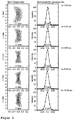
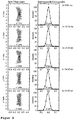
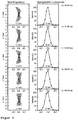
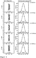
- Figuren 3-6:
- Simulierte Spektralverteilungen (Spot-Diagramme) und entsprechende instrumentelle Profile für vier verschiedene Wellenlängenbereiche sowie dazu korrespondierende Sätze an Gitterparametern.
- FIG. 1:
- Construction of a spectrometer (from above).
- FIG. 2:
- Sketch of the holographic grid exposure (from above).
- Figures 3-6:
- Simulated spectral distributions (spot diagrams) and corresponding instrumental profiles for four different wavelength ranges as well as corresponding sets of lattice parameters.
Die Forschungszentrum Jülich GmbH beteiligt sich seit 1999 an der Entwicklung von Diagnostik für das neue Plasmaexperiment W7-X, das ca. 2008 in Greifswald in Betrieb gehen wird. Im Bereich der VUV -Spektroskopie sollten dabei Spektrometer entwickelt werden, die insgesamt den Wellenlängenbereich von 2,5 nm bis 160 nm lückenlos abdecken sollen.Since 1999, Forschungszentrum Jülich GmbH has participated in the development of diagnostics for the new plasma experiment W7-X, which will be commissioned in Greifswald around 2008. In the field of VUV spectroscopy, spectrometers were to be developed which should cover the entire wavelength range from 2.5 nm to 160 nm without gaps.
Im Rahmen der hier verwendeten Technologie lässt sich eine weitere Vergrößerung des beobachteten Wellenlängenbereiches (bis etwa 1 nm bzw. bis etwa 200 nm) und/oder eine Steigerung der Auflösung grundsätzlich durch eine Vermehrung der Anzahl der Geräte bei entsprechend anderer Wahl der Wellenlängensegmente erreichen. Für den vorliegenden Fall stellte die Anzahl von 4 Spektrometern einen vertretbaren Kompromiss zwischen verfügbarem Budget und den an W7-X verfügbaren U-10 Beobachtungsstutzen dar.In the context of the technology used here, a further enlargement of the observed wavelength range (up to about 1 nm or up to about 200 nm) and / or an increase in resolution can be achieved basically by an increase in the number of devices with a correspondingly different selection of the wavelength segments. For the present case, the number of 4 spectrometers represented a reasonable compromise between available budget and the U-10 observation ports available on W7-X.
Im Rahmen dieser Erfindung wurden folgende vier Spektrometer mit optimierten Beugungsgittern für vier gering überlappende Wellenlängenbereiche entwickelt:
Bei der Festlegung der Wellenlängenbereiche wurden die spektrale Lage wichtiger Spektrallinien sowie die Verfügbarkeit von Kalibriermethoden und -lichtquellen berücksichtigt. Die neuen Spektrometer sollen eine hohe Effizienz aufweisen, um Untersuchungen mit hoher Zeitauflösung zu ermöglichen, gleichzeitig aber eine gute Wellenlängenauflösung besitzen, damit viele Spektrallinien gleichzeitig isoliert beobachtet werden können. Die Gesamteffizienz des Spektrometers ergibt sich aus dem Produkt aus effektiver Etendue, Gittereffizienz (dies ist der Bruchteil des einfallenden Lichts, der in die erste Beugungsordnung abgelenkt wird) und der Nachweiseffizienz des Detektors. Die effektive Etendue ist das Produkt dreier Größen: Ausgeleuchtete Fläche des Eintrittsspalts; ausgeleuchteter Raumwinkel; Anteil der vom Gitter kommenden Strahlen, die den Detektor innerhalb seiner sensitiven Fläche treffen.When determining the wavelength ranges, the spectral position of important spectral lines as well as the availability of calibration methods and light sources were taken into account. The new spectrometers should have a high Have efficiency to allow studies with high time resolution, but at the same time have a good wavelength resolution, so that many spectral lines can be observed simultaneously isolated. The overall efficiency of the spectrometer results from the product of effective etendue, lattice efficiency (this is the fraction of incident light that is deflected into the first order of diffraction) and the detection efficiency of the detector. The effective etendue is the product of three sizes: illuminated area of the entrance slit; illuminated solid angle; Proportion of rays coming from the grating that hit the detector within its sensitive area.
Derzeit existieren für eine solche Anwendung keine geeigneten Standardgitter. Gitterhersteller wie Jobin-Yvon/Horiba (führender Hersteller holographischer Gitter) oder Zeiss (Spezialist für verschiedene Sonderanfertigungen bei Optik, auch holographische Gitter) verfügen jedoch über die Technologie zur Herstellung holographischer Gitter, sofern die dazu erforderlichen Gitterparameter vorgegeben werden.At present, no suitable standard gratings exist for such an application. However, lattice manufacturers such as Jobin-Yvon / Horiba (leading manufacturer of holographic gratings) or Zeiss (specialist for various special designs in optics, including holographic gratings) have the technology for producing holographic gratings, as long as the required grating parameters are specified.
Dazu ist jedoch zunächst die Bestimmung der sieben Parameter eines holographischen Beugungsgitters für ein entsprechendes VUV-Spektrometer mit ebenem Detektor notwendig, so dass bei vorgegebenen Spektrometerparametern (Abmessungen, Abstände, Winkel, Wellenlängenbereich) eine minimale Linienbreite am Detektor (gemittelt über den Wellenlängenbereich) bei hoher Etendue (Lichtstärke) erzielt wird.For this purpose, however, first the determination of the seven parameters of a holographic diffraction grating for a corresponding VUV spectrometer with level detector is necessary, so that at given Spektrometerparametern (dimensions, distances, angles, wavelength range) a minimum line width at the detector (averaged over the wavelength range) at high Etendue (light intensity) is achieved.
Geeignete Designs holographischer korrigierter Gitter für die zu entwickelnden Spektrometer stehen bei den Gitterherstellern regelmäßig nicht zur Verfügung.Suitable designs of holographic corrected gratings for the spectrometers to be developed are regularly not available from the lattice manufacturers.
Rowlandgitter für die genannten Wellenlängenbereiche sind teilweise verfügbar. Eine Verwendung solcher Gitter führt nachteilig zu Spektrometern, die eine erheblich geringere Etendue (Faktor 2 - 10) und eine schlechtere Auflösung aufweisen, als es mit korrigierten holographischen Gittern erreicht werden kann.Rowland gratings for the mentioned wavelength ranges are partially available. Use of such gratings adversely results in spectrometers that have a significantly lower etendue (factor 2-10) and poorer resolution than can be achieved with corrected holographic gratings.
Es wurde im Rahmen der Erfindung gefunden, dass zur Lösung der Aufgabe die mittlere Linienbreite der "Spektrallinien" auf der Detektorebene zu minimieren ist. Die Variablen, bezüglich derer das Minimum gesucht wird, sind die sieben Gitterparameter. Als Randbedingungen werden die Spektrometerparameter, wie beispielsweise Abmessungen, Abstände, Winkel und Wellenlängenbereich zunächst vorgegeben. Diese werden im weiteren Verfahren jedoch innerhalb entsprechender Bandbreiten, die sich aus mechanischen und/oder physikalischen Gegebenheiten herleiten lassen, ebenfalls variiert.It has been found within the scope of the invention that to solve the problem, the mean line width of the "spectral lines" at the detector level is to be minimized. The variables with respect to which the minimum is sought are the seven grid parameters. As boundary conditions, the spectrometer parameters, such as dimensions, distances, angles and wavelength range are initially specified. However, these are also varied in the further process within corresponding bandwidths, which can be derived from mechanical and / or physical conditions.
Nachfolgend werden die Ergebnisse von 4 Ausführungsbeispielen für neue Gitterdesigns dargestellt. Dabei gelten folgende Bezeichnungen:The results of 4 embodiments for new grid designs are shown below. The following designations apply:
- R:R:
- Großer Radius des toroidalen GittersubstratesLarge radius of the toroidal lattice substrate
- ρ:ρ:
- Kleiner Radius des toroidalen GittersubstratesSmall radius of the toroidal lattice substrate
- rc, rd:r c , r d :
- Abstände der holographischen Beleuchtungspunkte vom GitterursprungDistances of the holographic illumination points from the grid origin
- γ, δ:γ, δ:
- Winkelstellung der holographischen Beleuchtungspunkte zur GitternormalenAngular position of the holographic illumination points to the lattice normal
- λL:λ L :
- LaserwellenlängeLaser wavelength
- LA :L A :
- Abstand Eintrittsspalt -GittermittelpunktDistance between entrance slit - grid center
- rso:r like this :
- Abstand vom Gitterursprung zum meridionalen Fokus nullter OrdnungDistance from the grid origin to the zero-order meridional focus
- LB:L B :
- Abstand Gittermittelpunkt -DetektorDistance grid center detector
- α:α:
- Einfallswinkel der Strahlung zur GitternormalenAngle of incidence of the radiation to the lattice normal
- β:β:
- Ausfallswinkel der Strahlung zur GitternormalenFailure angle of the radiation to the lattice normal
- λ :λ:
- Wellenlänge der Strahlung innerhalb eines zuvor definierten WellenlängenbereichsWavelength of the radiation within a previously defined wavelength range
- G:G:
- Strichdichte im GitterursprungLine density in the grid origin
- MCP angle:MCP angle:
- Anstellwinkel des Detektors relativ zur GittertangenteIncident angle of the detector relative to the grating tangent
- TH:TH:
- Anteil der ausfallenden Strahlen, die den Detektor innerhalb eines vertikalen Bereichs vorgegebener Höhe treffenProportion of failing beams hitting the detector within a vertical range of given height
Design 1 ist für ein Spektrometer im Wellenlängenbereich von 2,5 nm bis 10,5 nm, Design 2 ist für ein Spektrometer im Wellenlängenbereich von 9,0 nm bis 24,0 nm, Design 3 ist für ein Spektrometer im Wellenlängenvon 20 nm bis 66 nm und Design 4 ist für ein Spektrometer im Wellenlängenbereich von 60 nm bis 160 nm bestimmt worden, wobei alle vier neuen Designs am Fusionsexperiment W7-X eingesetzt werden soll. In der nachfolgenden Beschreibung der vier
Claims (10)
- Method for determining a set of grating parameters for the holographic production of a diffraction grating which has a toroidal grating substrate, for a VUV spectrometer configuration,
in which- the wavelength range to be observed and- the detector measurement are specified,and wherein the set of grating parameters comprises, in addition to the specified laser wavelength λL for the holographic illumination,- the small radius and the large radius of the toroidal grating substrate (ρ and R),- the two distances of the two holographic illumination points from the grating origin (re and rd), and- the angular position of the holographic illumination points relative to the grating normal (γ and δ),and wherein the following spectrometer parameters are firstly specified as boundary conditionsi. the measurements of the inlet gap,ii. the distance LA of the inlet gap from the grating origin,iii. distance Rso from the grating origin to the meridional focus of zero order, wherein the line density of the grating does not exceed 2500 per mm,iv. the incident angle and the angle of reflection of the radiation relative to the grating normal,v. the position and angular position of the detector, wherein light of the first order from the grating falls upon the detector,vi. width and height of the diffraction grating,whereina) the large radius R of the toroidal grating substrate is determined from the meridional focus condition of zero order,b) the small radius ρ of the toroidal grating substrate, the line density G at the grating centre point and the wavelength λm at the detector centre point are iteratively determined using the grating equation and using the sagittal focus condition for the first diffraction order,c) of the remaining four variables, namely the distances of the two holographic illumination points from the grating origin (re and rd) and their angular positions relative to the grating normal (γ and δ), one of the two angles (γ) is eliminated based upon the mean line count of the grating,d) the minimum of the value Δλ, the mean line width at the detector over all wavelengths of the wavelength range to be observed, is determined iteratively as a function of the three remaining variables (distances rc, rD and angle δ), wherein the set of variables rc, rD and δ is considered a solution for which Δλ takes an absolute minimum. - Method according to claim 1, in which, on the basis of the grating parameters obtained and the boundary conditions of the spectrometer specified in this case, the mean line width and effective etendue are obtained.
- Method according to any of claims 1 to 2, in which the steps a) to d) are repeated for at least ten different configurations of grating and/or gap measurements and/or arm lengths, corresponding to the points i. to iii. in claim 1.
- Computer program which can be loaded into a memory of a digital computer and has a software code for carrying out a method according to any of claims 1 to 3.
- Computer system having a computer program according to the preceding claim.
- Method according to any of claims 1 to 3, in which the grating parameters obtained are used to produce a diffraction grating.
- Method for producing a diffraction grating- in which the laser wavelength for the holographic illumination is established at (λL) = 487,98 nm,- in which the wavelength range determined is from 2,5 to 10,5 nm, and- in which the following grating parameters obtained using a method according to claim 1 to 3 are used:large radius of the toroidal grating substrate (R) = 6451 mm,small radius of the toroidal grating substrate (ρ) = 52,0 mm,distances of the illumination points from the grating origin (rc) = 328 mm, (rd) = 1000 mm,angular position of the illumination points relative to the grating origin (γ) = 4,74 and (δ) = 75,0.
- Method for producing a diffraction grating- in which the laser wavelength for the holographic illumination is established at (λL) = 487,98 nm,- in which the wavelength range determined is from 9 to 24 nm, and- in which the following grating parameters obtained using a method according to claim 1 to 3 are used:large radius of the toroidal grating substrate (R) = 1860 mm,small radius of the toroidal grating substrate (ρ) = 132,8 mm,distances of the illumination points from the grating origin (rc) = 327 mm, (rd) = 1000 mm,angular position of the illumination points relative to the grating normal (γ) = -2,65 and (δ) = 75,0.
- Method for producing a diffraction grating- in which the laser wavelength for the holographic illumination is established at (λL) = 487,98 nm.- in which the wavelength range determined is from 20 to 66 nm, and- in which the following grating parameters obtained using a method according to claim 1 to 3 are used:large radius of the toroidal grating substrate (R) = 828,2 mm,small radius of the toroidal grating substrate (ρ) = 165,7 mm,distances of the illumination points from the grating origin (rc) = 337 mm, (rd) = 1000 mm,angular position of the illumination points relative to the grating origin (γ) = 19,6 and (δ) = 75,0.
- Method for producing a diffraction grating- in which the laser wavelength for the holographic illumination is established at (λL) = 487,98 nm,- in which the wavelength range determined is from 60 to 160 nm, and- in which the following grating parameters obtained using a method according to claim 1 to 3 are used:large radius of the toroidal grating substrate (R) = 495 mm,small radius of the toroidal grating substrate (ρ) = 164,2 mm,distances of the illumination points from the grating origin (rc) = 362 mm, (rd) = 1000 mm,angular position of the illumination points relative to the grating normal (γ) = 32,6 and (δ) = 75,0.
Applications Claiming Priority (3)
| Application Number | Priority Date | Filing Date | Title |
|---|---|---|---|
| DE10307884A DE10307884A1 (en) | 2003-02-25 | 2003-02-25 | Method for determining optimal grating parameters for the production of a diffraction grating for a VUV spectrometer |
| DE10307884 | 2003-02-25 | ||
| PCT/DE2004/000058 WO2004076996A1 (en) | 2003-02-25 | 2004-01-17 | Method for determining optimum grating parameters for producing a diffraction grating for a vuv spectrometer |
Publications (2)
| Publication Number | Publication Date |
|---|---|
| EP1597548A1 EP1597548A1 (en) | 2005-11-23 |
| EP1597548B1 true EP1597548B1 (en) | 2019-11-20 |
Family
ID=32841840
Family Applications (1)
| Application Number | Title | Priority Date | Filing Date |
|---|---|---|---|
| EP04703091.1A Expired - Lifetime EP1597548B1 (en) | 2003-02-25 | 2004-01-17 | Method for determining optimum grating parameters for producing a diffraction grating for a vuv spectrometer |
Country Status (6)
| Country | Link |
|---|---|
| US (1) | US7420736B2 (en) |
| EP (1) | EP1597548B1 (en) |
| JP (1) | JP2006518865A (en) |
| DE (1) | DE10307884A1 (en) |
| ES (1) | ES2764753T3 (en) |
| WO (1) | WO2004076996A1 (en) |
Families Citing this family (5)
| Publication number | Priority date | Publication date | Assignee | Title |
|---|---|---|---|---|
| DE102008012635A1 (en) * | 2008-03-05 | 2009-09-10 | Carl Zeiss Microlmaging Gmbh | Method and arrangement for time-resolved spectroscopy |
| JP5440110B2 (en) | 2009-03-30 | 2014-03-12 | 株式会社リコー | Spectral characteristic acquisition apparatus, spectral characteristic acquisition method, image evaluation apparatus, and image forming apparatus |
| KR101446902B1 (en) * | 2011-08-19 | 2014-10-07 | 한국전자통신연구원 | Method and apparatus for user interraction |
| RU2661742C1 (en) * | 2017-07-18 | 2018-07-19 | Общество с ограниченной ответственностью "РнД-ИСАН" | Compact wide range vuv spectrometer |
| CN114815024B (en) * | 2022-05-19 | 2023-08-08 | 南京工业职业技术大学 | Exposure area calculation method for batch preparation of holographic diffraction waveguides and application thereof |
Family Cites Families (3)
| Publication number | Priority date | Publication date | Assignee | Title |
|---|---|---|---|---|
| FR2309844A1 (en) * | 1975-04-28 | 1976-11-26 | Instruments Sa | SINGLE ROTATION MONOCHROMATOR OF THE NETWORK FOR USE IN THE ULTRAVIOLET |
| US4241999A (en) * | 1978-08-24 | 1980-12-30 | Agence Nationale De Valorisation De La Recherche (Anvar) | Monochromators |
| US5052766A (en) * | 1986-12-11 | 1991-10-01 | Shimadzu Corporation | Halographic grating and optical device incorporating the same |
-
2003
- 2003-02-25 DE DE10307884A patent/DE10307884A1/en not_active Withdrawn
-
2004
- 2004-01-17 ES ES04703091T patent/ES2764753T3/en not_active Expired - Lifetime
- 2004-01-17 JP JP2006501463A patent/JP2006518865A/en active Pending
- 2004-01-17 EP EP04703091.1A patent/EP1597548B1/en not_active Expired - Lifetime
- 2004-01-17 US US10/547,145 patent/US7420736B2/en not_active Expired - Fee Related
- 2004-01-17 WO PCT/DE2004/000058 patent/WO2004076996A1/en active Application Filing
Non-Patent Citations (1)
| Title |
|---|
| None * |
Also Published As
| Publication number | Publication date |
|---|---|
| US7420736B2 (en) | 2008-09-02 |
| DE10307884A1 (en) | 2004-09-09 |
| WO2004076996A1 (en) | 2004-09-10 |
| US20060146344A1 (en) | 2006-07-06 |
| EP1597548A1 (en) | 2005-11-23 |
| JP2006518865A (en) | 2006-08-17 |
| ES2764753T3 (en) | 2020-06-04 |
Similar Documents
| Publication | Publication Date | Title |
|---|---|---|
| EP3098581B1 (en) | Method for correcting background signals in a spectrum | |
| DE112017005271T5 (en) | ENTIRE METROLOGY FOR X-RAY SCATTEROMETRY SYSTEMS | |
| DE102015100395B4 (en) | Spectrometer and fluid analysis system | |
| DE102009003413B4 (en) | Echelle spectrometer arrangement with internal pre-dispersion | |
| EP2793056B1 (en) | Device and method for determining the energetic composition of electromagnetic waves | |
| DE112020004109T5 (en) | Methods and systems for semiconductor metrology based on soft X-ray reflectometry with wavelength resolution | |
| EP1647840B1 (en) | X-ray-optical or neutron-optical analyser comprising a stripdetector having variable light-transmission | |
| DE19955556A1 (en) | Measurement arrangement for parallel read-out of surface plasmon resonance sensors passes waveguide's output light to CCD chip via optics, derives intensity | |
| DE112021002841T5 (en) | System and method for X-ray absorption spectroscopy using a crystal analyzer and multiple detector elements | |
| DE112017000464T5 (en) | Single wavelength ellipsometry with improved spot size capability | |
| DE112016001974B4 (en) | Method for measuring the angle of rotation using a Fabry-Pérot etalon | |
| DE102016206088A1 (en) | Method for determining the thickness of a contaminating layer and / or the type of contaminating material, optical element and EUV lithography system | |
| EP1597548B1 (en) | Method for determining optimum grating parameters for producing a diffraction grating for a vuv spectrometer | |
| WO2010127872A1 (en) | Device and method for angularly resolved scattered light measurement | |
| DE112017008083T5 (en) | REMOTE INFRARED LIGHT SOURCE AND REMOTE INFRARED SPECTROMETER | |
| DE102015108818A1 (en) | Arrangement for spectroscopy and method for producing the arrangement | |
| DE102013008486B4 (en) | Low-noise optical element for detecting radiation by measuring electrical signals and using the same to set a reflection condition | |
| DE1909841C3 (en) | spectrometer | |
| WO2009083164A1 (en) | Grating mirror for the online monitoring of a laser beam, and monitoring device comprising the same | |
| EP3977074A1 (en) | Method, device and system for detecting raman scattered light | |
| DE102018119712A1 (en) | DEVICE FOR CONDUCTING RADIATION, A PHOTODETECTOR ARRANGEMENT AND A METHOD FOR LOCALLY RESOLVED SPECTRAL ANALYSIS | |
| EP1403634A1 (en) | Arrangement for the determination of the spectral reflectivity of an object | |
| DE19542679A1 (en) | X=ray spectrograph optics | |
| DE102013108587A1 (en) | An electron beam detector, electron beam working apparatus and method of manufacturing an electron beam detector | |
| DE102018133042B4 (en) | Method and device for calibrating spectrometers |
Legal Events
| Date | Code | Title | Description |
|---|---|---|---|
| PUAI | Public reference made under article 153(3) epc to a published international application that has entered the european phase |
Free format text: ORIGINAL CODE: 0009012 |
|
| 17P | Request for examination filed |
Effective date: 20050714 |
|
| AK | Designated contracting states |
Kind code of ref document: A1 Designated state(s): AT BE BG CH CY CZ DE DK EE ES FI FR GB GR HU IE IT LI LU MC NL PT RO SE SI SK TR |
|
| AX | Request for extension of the european patent |
Extension state: AL LT LV MK |
|
| DAX | Request for extension of the european patent (deleted) | ||
| 17Q | First examination report despatched |
Effective date: 20061005 |
|
| RAP1 | Party data changed (applicant data changed or rights of an application transferred) |
Owner name: THE EUROPEAN ATOMIC ENERGY COMMUNITY (EURATOM), RE Owner name: FORSCHUNGSZENTRUM JUELICH GMBH |
|
| RAP1 | Party data changed (applicant data changed or rights of an application transferred) |
Owner name: THE EUROPEAN ATOMIC ENERGY COMMUNITY (EURATOM), RE |
|
| STAA | Information on the status of an ep patent application or granted ep patent |
Free format text: STATUS: EXAMINATION IS IN PROGRESS |
|
| GRAP | Despatch of communication of intention to grant a patent |
Free format text: ORIGINAL CODE: EPIDOSNIGR1 |
|
| STAA | Information on the status of an ep patent application or granted ep patent |
Free format text: STATUS: GRANT OF PATENT IS INTENDED |
|
| INTG | Intention to grant announced |
Effective date: 20190614 |
|
| GRAS | Grant fee paid |
Free format text: ORIGINAL CODE: EPIDOSNIGR3 |
|
| GRAA | (expected) grant |
Free format text: ORIGINAL CODE: 0009210 |
|
| STAA | Information on the status of an ep patent application or granted ep patent |
Free format text: STATUS: THE PATENT HAS BEEN GRANTED |
|
| AK | Designated contracting states |
Kind code of ref document: B1 Designated state(s): AT BE BG CH CY CZ DE DK EE ES FI FR GB GR HU IE IT LI LU MC NL PT RO SE SI SK TR |
|
| REG | Reference to a national code |
Ref country code: GB Ref legal event code: FG4D Free format text: NOT ENGLISH |
|
| REG | Reference to a national code |
Ref country code: CH Ref legal event code: EP |
|
| REG | Reference to a national code |
Ref country code: DE Ref legal event code: R096 Ref document number: 502004015840 Country of ref document: DE |
|
| REG | Reference to a national code |
Ref country code: IE Ref legal event code: FG4D Free format text: LANGUAGE OF EP DOCUMENT: GERMAN |
|
| REG | Reference to a national code |
Ref country code: AT Ref legal event code: REF Ref document number: 1204712 Country of ref document: AT Kind code of ref document: T Effective date: 20191215 |
|
| REG | Reference to a national code |
Ref country code: NL Ref legal event code: MP Effective date: 20191120 |
|
| PG25 | Lapsed in a contracting state [announced via postgrant information from national office to epo] |
Ref country code: BG Free format text: LAPSE BECAUSE OF FAILURE TO SUBMIT A TRANSLATION OF THE DESCRIPTION OR TO PAY THE FEE WITHIN THE PRESCRIBED TIME-LIMIT Effective date: 20200220 Ref country code: FI Free format text: LAPSE BECAUSE OF FAILURE TO SUBMIT A TRANSLATION OF THE DESCRIPTION OR TO PAY THE FEE WITHIN THE PRESCRIBED TIME-LIMIT Effective date: 20191120 Ref country code: GR Free format text: LAPSE BECAUSE OF FAILURE TO SUBMIT A TRANSLATION OF THE DESCRIPTION OR TO PAY THE FEE WITHIN THE PRESCRIBED TIME-LIMIT Effective date: 20200221 Ref country code: SE Free format text: LAPSE BECAUSE OF FAILURE TO SUBMIT A TRANSLATION OF THE DESCRIPTION OR TO PAY THE FEE WITHIN THE PRESCRIBED TIME-LIMIT Effective date: 20191120 Ref country code: NL Free format text: LAPSE BECAUSE OF FAILURE TO SUBMIT A TRANSLATION OF THE DESCRIPTION OR TO PAY THE FEE WITHIN THE PRESCRIBED TIME-LIMIT Effective date: 20191120 |
|
| REG | Reference to a national code |
Ref country code: ES Ref legal event code: FG2A Ref document number: 2764753 Country of ref document: ES Kind code of ref document: T3 Effective date: 20200604 |
|
| PG25 | Lapsed in a contracting state [announced via postgrant information from national office to epo] |
Ref country code: PT Free format text: LAPSE BECAUSE OF FAILURE TO SUBMIT A TRANSLATION OF THE DESCRIPTION OR TO PAY THE FEE WITHIN THE PRESCRIBED TIME-LIMIT Effective date: 20200412 Ref country code: EE Free format text: LAPSE BECAUSE OF FAILURE TO SUBMIT A TRANSLATION OF THE DESCRIPTION OR TO PAY THE FEE WITHIN THE PRESCRIBED TIME-LIMIT Effective date: 20191120 Ref country code: DK Free format text: LAPSE BECAUSE OF FAILURE TO SUBMIT A TRANSLATION OF THE DESCRIPTION OR TO PAY THE FEE WITHIN THE PRESCRIBED TIME-LIMIT Effective date: 20191120 Ref country code: RO Free format text: LAPSE BECAUSE OF FAILURE TO SUBMIT A TRANSLATION OF THE DESCRIPTION OR TO PAY THE FEE WITHIN THE PRESCRIBED TIME-LIMIT Effective date: 20191120 Ref country code: CZ Free format text: LAPSE BECAUSE OF FAILURE TO SUBMIT A TRANSLATION OF THE DESCRIPTION OR TO PAY THE FEE WITHIN THE PRESCRIBED TIME-LIMIT Effective date: 20191120 |
|
| REG | Reference to a national code |
Ref country code: DE Ref legal event code: R097 Ref document number: 502004015840 Country of ref document: DE |
|
| PG25 | Lapsed in a contracting state [announced via postgrant information from national office to epo] |
Ref country code: MC Free format text: LAPSE BECAUSE OF FAILURE TO SUBMIT A TRANSLATION OF THE DESCRIPTION OR TO PAY THE FEE WITHIN THE PRESCRIBED TIME-LIMIT Effective date: 20191120 Ref country code: SK Free format text: LAPSE BECAUSE OF FAILURE TO SUBMIT A TRANSLATION OF THE DESCRIPTION OR TO PAY THE FEE WITHIN THE PRESCRIBED TIME-LIMIT Effective date: 20191120 |
|
| REG | Reference to a national code |
Ref country code: CH Ref legal event code: PL |
|
| PLBE | No opposition filed within time limit |
Free format text: ORIGINAL CODE: 0009261 |
|
| STAA | Information on the status of an ep patent application or granted ep patent |
Free format text: STATUS: NO OPPOSITION FILED WITHIN TIME LIMIT |
|
| REG | Reference to a national code |
Ref country code: BE Ref legal event code: MM Effective date: 20200131 |
|
| 26N | No opposition filed |
Effective date: 20200821 |
|
| PG25 | Lapsed in a contracting state [announced via postgrant information from national office to epo] |
Ref country code: LU Free format text: LAPSE BECAUSE OF NON-PAYMENT OF DUE FEES Effective date: 20200117 |
|
| PG25 | Lapsed in a contracting state [announced via postgrant information from national office to epo] |
Ref country code: CH Free format text: LAPSE BECAUSE OF NON-PAYMENT OF DUE FEES Effective date: 20200131 Ref country code: BE Free format text: LAPSE BECAUSE OF NON-PAYMENT OF DUE FEES Effective date: 20200131 Ref country code: SI Free format text: LAPSE BECAUSE OF FAILURE TO SUBMIT A TRANSLATION OF THE DESCRIPTION OR TO PAY THE FEE WITHIN THE PRESCRIBED TIME-LIMIT Effective date: 20191120 Ref country code: LI Free format text: LAPSE BECAUSE OF NON-PAYMENT OF DUE FEES Effective date: 20200131 |
|
| PG25 | Lapsed in a contracting state [announced via postgrant information from national office to epo] |
Ref country code: IE Free format text: LAPSE BECAUSE OF NON-PAYMENT OF DUE FEES Effective date: 20200117 |
|
| REG | Reference to a national code |
Ref country code: AT Ref legal event code: MM01 Ref document number: 1204712 Country of ref document: AT Kind code of ref document: T Effective date: 20200117 |
|
| PG25 | Lapsed in a contracting state [announced via postgrant information from national office to epo] |
Ref country code: AT Free format text: LAPSE BECAUSE OF NON-PAYMENT OF DUE FEES Effective date: 20200117 |
|
| PGFP | Annual fee paid to national office [announced via postgrant information from national office to epo] |
Ref country code: FR Payment date: 20211201 Year of fee payment: 19 |
|
| PGFP | Annual fee paid to national office [announced via postgrant information from national office to epo] |
Ref country code: GB Payment date: 20220118 Year of fee payment: 19 Ref country code: DE Payment date: 20220127 Year of fee payment: 19 |
|
| PG25 | Lapsed in a contracting state [announced via postgrant information from national office to epo] |
Ref country code: TR Free format text: LAPSE BECAUSE OF FAILURE TO SUBMIT A TRANSLATION OF THE DESCRIPTION OR TO PAY THE FEE WITHIN THE PRESCRIBED TIME-LIMIT Effective date: 20191120 Ref country code: CY Free format text: LAPSE BECAUSE OF FAILURE TO SUBMIT A TRANSLATION OF THE DESCRIPTION OR TO PAY THE FEE WITHIN THE PRESCRIBED TIME-LIMIT Effective date: 20191120 |
|
| PGFP | Annual fee paid to national office [announced via postgrant information from national office to epo] |
Ref country code: IT Payment date: 20220119 Year of fee payment: 19 Ref country code: ES Payment date: 20220211 Year of fee payment: 19 |
|
| REG | Reference to a national code |
Ref country code: DE Ref legal event code: R119 Ref document number: 502004015840 Country of ref document: DE |
|
| GBPC | Gb: european patent ceased through non-payment of renewal fee |
Effective date: 20230117 |
|
| PG25 | Lapsed in a contracting state [announced via postgrant information from national office to epo] |
Ref country code: GB Free format text: LAPSE BECAUSE OF NON-PAYMENT OF DUE FEES Effective date: 20230117 Ref country code: DE Free format text: LAPSE BECAUSE OF NON-PAYMENT OF DUE FEES Effective date: 20230801 |
|
| PG25 | Lapsed in a contracting state [announced via postgrant information from national office to epo] |
Ref country code: FR Free format text: LAPSE BECAUSE OF NON-PAYMENT OF DUE FEES Effective date: 20230131 |
|
| PG25 | Lapsed in a contracting state [announced via postgrant information from national office to epo] |
Ref country code: IT Free format text: LAPSE BECAUSE OF NON-PAYMENT OF DUE FEES Effective date: 20230117 |
|
| REG | Reference to a national code |
Ref country code: ES Ref legal event code: FD2A Effective date: 20240327 |
|
| PG25 | Lapsed in a contracting state [announced via postgrant information from national office to epo] |
Ref country code: ES Free format text: LAPSE BECAUSE OF NON-PAYMENT OF DUE FEES Effective date: 20230118 |