EP1597109B9 - Method of forming a seat system - Google Patents
Method of forming a seat system Download PDFInfo
- Publication number
- EP1597109B9 EP1597109B9 EP20040709933 EP04709933A EP1597109B9 EP 1597109 B9 EP1597109 B9 EP 1597109B9 EP 20040709933 EP20040709933 EP 20040709933 EP 04709933 A EP04709933 A EP 04709933A EP 1597109 B9 EP1597109 B9 EP 1597109B9
- Authority
- EP
- European Patent Office
- Prior art keywords
- reinforcement
- panel
- amine
- adhesive
- corresponding surface
- Prior art date
- Legal status (The legal status is an assumption and is not a legal conclusion. Google has not performed a legal analysis and makes no representation as to the accuracy of the status listed.)
- Expired - Lifetime
Links
- 238000000034 method Methods 0.000 title claims description 34
- 230000002787 reinforcement Effects 0.000 claims abstract description 119
- 239000004033 plastic Substances 0.000 claims abstract description 26
- 229920003023 plastic Polymers 0.000 claims abstract description 26
- 239000000463 material Substances 0.000 claims description 57
- 239000000853 adhesive Substances 0.000 claims description 44
- 230000001070 adhesive effect Effects 0.000 claims description 44
- 150000001412 amines Chemical class 0.000 claims description 39
- -1 polybutylene Polymers 0.000 claims description 29
- 150000001875 compounds Chemical class 0.000 claims description 20
- 239000004743 Polypropylene Substances 0.000 claims description 15
- 229920001155 polypropylene Polymers 0.000 claims description 15
- 239000001257 hydrogen Substances 0.000 claims description 14
- 229910052739 hydrogen Inorganic materials 0.000 claims description 14
- IJGRMHOSHXDMSA-UHFFFAOYSA-N Atomic nitrogen Chemical compound N#N IJGRMHOSHXDMSA-UHFFFAOYSA-N 0.000 claims description 12
- 239000003365 glass fiber Substances 0.000 claims description 11
- UORVGPXVDQYIDP-UHFFFAOYSA-N borane Chemical compound B UORVGPXVDQYIDP-UHFFFAOYSA-N 0.000 claims description 10
- 239000000835 fiber Substances 0.000 claims description 10
- 229920000642 polymer Polymers 0.000 claims description 10
- 239000004952 Polyamide Substances 0.000 claims description 9
- 239000011521 glass Substances 0.000 claims description 9
- 150000002466 imines Chemical class 0.000 claims description 9
- 229910052751 metal Inorganic materials 0.000 claims description 9
- 239000002184 metal Substances 0.000 claims description 9
- 229920002647 polyamide Polymers 0.000 claims description 9
- 150000003141 primary amines Chemical class 0.000 claims description 9
- 150000001409 amidines Chemical class 0.000 claims description 7
- 229910000085 borane Inorganic materials 0.000 claims description 7
- 239000000956 alloy Substances 0.000 claims description 6
- 229910045601 alloy Inorganic materials 0.000 claims description 6
- 125000000623 heterocyclic group Chemical group 0.000 claims description 6
- 229910052757 nitrogen Inorganic materials 0.000 claims description 6
- 238000006116 polymerization reaction Methods 0.000 claims description 6
- 229910000831 Steel Inorganic materials 0.000 claims description 5
- 239000010959 steel Substances 0.000 claims description 5
- RTZKZFJDLAIYFH-UHFFFAOYSA-N Diethyl ether Chemical compound CCOCC RTZKZFJDLAIYFH-UHFFFAOYSA-N 0.000 claims description 4
- 239000004793 Polystyrene Substances 0.000 claims description 4
- 239000004676 acrylonitrile butadiene styrene Substances 0.000 claims description 4
- 125000004432 carbon atom Chemical group C* 0.000 claims description 4
- 238000001746 injection moulding Methods 0.000 claims description 4
- 239000000178 monomer Substances 0.000 claims description 4
- 229920002223 polystyrene Polymers 0.000 claims description 4
- 229920000122 acrylonitrile butadiene styrene Polymers 0.000 claims description 3
- 229910052782 aluminium Inorganic materials 0.000 claims description 3
- XAGFODPZIPBFFR-UHFFFAOYSA-N aluminium Chemical compound [Al] XAGFODPZIPBFFR-UHFFFAOYSA-N 0.000 claims description 3
- 230000015572 biosynthetic process Effects 0.000 claims description 3
- 150000002170 ethers Chemical class 0.000 claims description 3
- ASUDFOJKTJLAIK-UHFFFAOYSA-N 2-methoxyethanamine Chemical compound COCCN ASUDFOJKTJLAIK-UHFFFAOYSA-N 0.000 claims description 2
- RNLHGQLZWXBQNY-UHFFFAOYSA-N 3-(aminomethyl)-3,5,5-trimethylcyclohexan-1-amine Chemical compound CC1(C)CC(N)CC(C)(CN)C1 RNLHGQLZWXBQNY-UHFFFAOYSA-N 0.000 claims description 2
- SOYBEXQHNURCGE-UHFFFAOYSA-N 3-ethoxypropan-1-amine Chemical compound CCOCCCN SOYBEXQHNURCGE-UHFFFAOYSA-N 0.000 claims description 2
- FAXDZWQIWUSWJH-UHFFFAOYSA-N 3-methoxypropan-1-amine Chemical compound COCCCN FAXDZWQIWUSWJH-UHFFFAOYSA-N 0.000 claims description 2
- UIKUBYKUYUSRSM-UHFFFAOYSA-N 3-morpholinopropylamine Chemical compound NCCCN1CCOCC1 UIKUBYKUYUSRSM-UHFFFAOYSA-N 0.000 claims description 2
- UTOXFQVLOTVLSD-UHFFFAOYSA-N 3-propoxypropan-1-amine Chemical compound CCCOCCCN UTOXFQVLOTVLSD-UHFFFAOYSA-N 0.000 claims description 2
- ZJCCRDAZUWHFQH-UHFFFAOYSA-N Trimethylolpropane Chemical compound CCC(CO)(CO)CO ZJCCRDAZUWHFQH-UHFFFAOYSA-N 0.000 claims description 2
- XECAHXYUAAWDEL-UHFFFAOYSA-N acrylonitrile butadiene styrene Chemical compound C=CC=C.C=CC#N.C=CC1=CC=CC=C1 XECAHXYUAAWDEL-UHFFFAOYSA-N 0.000 claims description 2
- 239000004411 aluminium Substances 0.000 claims description 2
- 238000000748 compression moulding Methods 0.000 claims description 2
- IUNMPGNGSSIWFP-UHFFFAOYSA-N dimethylaminopropylamine Chemical group CN(C)CCCN IUNMPGNGSSIWFP-UHFFFAOYSA-N 0.000 claims description 2
- IZOKYNNJMLYHSO-UHFFFAOYSA-N hexane-1,4,4-triamine Chemical compound CCC(N)(N)CCCN IZOKYNNJMLYHSO-UHFFFAOYSA-N 0.000 claims description 2
- GCOWZPRIMFGIDQ-UHFFFAOYSA-N n',n'-dimethylbutane-1,4-diamine Chemical compound CN(C)CCCCN GCOWZPRIMFGIDQ-UHFFFAOYSA-N 0.000 claims description 2
- DILRJUIACXKSQE-UHFFFAOYSA-N n',n'-dimethylethane-1,2-diamine Chemical compound CN(C)CCN DILRJUIACXKSQE-UHFFFAOYSA-N 0.000 claims description 2
- 229920001281 polyalkylene Polymers 0.000 claims description 2
- 239000004417 polycarbonate Substances 0.000 claims description 2
- 229920000515 polycarbonate Polymers 0.000 claims description 2
- 229920000098 polyolefin Polymers 0.000 claims description 2
- 230000008569 process Effects 0.000 claims description 2
- 238000010526 radical polymerization reaction Methods 0.000 claims description 2
- 238000011282 treatment Methods 0.000 claims description 2
- 238000010102 injection blow moulding Methods 0.000 claims 1
- XNGIFLGASWRNHJ-UHFFFAOYSA-L phthalate(2-) Chemical compound [O-]C(=O)C1=CC=CC=C1C([O-])=O XNGIFLGASWRNHJ-UHFFFAOYSA-L 0.000 claims 1
- 229920001748 polybutylene Polymers 0.000 claims 1
- 125000002924 primary amino group Chemical group [H]N([H])* 0.000 claims 1
- 230000037452 priming Effects 0.000 claims 1
- 239000000203 mixture Substances 0.000 description 19
- 150000004985 diamines Chemical class 0.000 description 8
- 238000004519 manufacturing process Methods 0.000 description 7
- 238000013461 design Methods 0.000 description 6
- 125000000008 (C1-C10) alkyl group Chemical group 0.000 description 5
- UFHFLCQGNIYNRP-UHFFFAOYSA-N Hydrogen Chemical compound [H][H] UFHFLCQGNIYNRP-UHFFFAOYSA-N 0.000 description 5
- 238000000465 moulding Methods 0.000 description 5
- 125000004178 (C1-C4) alkyl group Chemical group 0.000 description 4
- 125000006376 (C3-C10) cycloalkyl group Chemical group 0.000 description 4
- 239000004721 Polyphenylene oxide Substances 0.000 description 4
- 238000005452 bending Methods 0.000 description 4
- 230000013011 mating Effects 0.000 description 4
- 229920006380 polyphenylene oxide Polymers 0.000 description 4
- 230000003014 reinforcing effect Effects 0.000 description 4
- 150000003335 secondary amines Chemical class 0.000 description 4
- XFNJVJPLKCPIBV-UHFFFAOYSA-N trimethylenediamine Chemical compound NCCCN XFNJVJPLKCPIBV-UHFFFAOYSA-N 0.000 description 4
- 230000001133 acceleration Effects 0.000 description 3
- 239000002253 acid Substances 0.000 description 3
- NIXOWILDQLNWCW-UHFFFAOYSA-M acrylate group Chemical group C(C=C)(=O)[O-] NIXOWILDQLNWCW-UHFFFAOYSA-M 0.000 description 3
- 125000000217 alkyl group Chemical group 0.000 description 3
- 230000008901 benefit Effects 0.000 description 3
- 239000007795 chemical reaction product Substances 0.000 description 3
- 239000007789 gas Substances 0.000 description 3
- 229920000768 polyamine Polymers 0.000 description 3
- PYSRRFNXTXNWCD-UHFFFAOYSA-N 3-(2-phenylethenyl)furan-2,5-dione Chemical compound O=C1OC(=O)C(C=CC=2C=CC=CC=2)=C1 PYSRRFNXTXNWCD-UHFFFAOYSA-N 0.000 description 2
- VHYFNPMBLIVWCW-UHFFFAOYSA-N 4-Dimethylaminopyridine Chemical compound CN(C)C1=CC=NC=C1 VHYFNPMBLIVWCW-UHFFFAOYSA-N 0.000 description 2
- QGZKDVFQNNGYKY-UHFFFAOYSA-N Ammonia Chemical compound N QGZKDVFQNNGYKY-UHFFFAOYSA-N 0.000 description 2
- SOGAXMICEFXMKE-UHFFFAOYSA-N Butylmethacrylate Chemical compound CCCCOC(=O)C(C)=C SOGAXMICEFXMKE-UHFFFAOYSA-N 0.000 description 2
- RPNUMPOLZDHAAY-UHFFFAOYSA-N Diethylenetriamine Chemical compound NCCNCCN RPNUMPOLZDHAAY-UHFFFAOYSA-N 0.000 description 2
- JOYRKODLDBILNP-UHFFFAOYSA-N Ethyl urethane Chemical compound CCOC(N)=O JOYRKODLDBILNP-UHFFFAOYSA-N 0.000 description 2
- XEEYBQQBJWHFJM-UHFFFAOYSA-N Iron Chemical compound [Fe] XEEYBQQBJWHFJM-UHFFFAOYSA-N 0.000 description 2
- VVQNEPGJFQJSBK-UHFFFAOYSA-N Methyl methacrylate Chemical compound COC(=O)C(C)=C VVQNEPGJFQJSBK-UHFFFAOYSA-N 0.000 description 2
- YNAVUWVOSKDBBP-UHFFFAOYSA-N Morpholine Chemical compound C1COCCN1 YNAVUWVOSKDBBP-UHFFFAOYSA-N 0.000 description 2
- GLUUGHFHXGJENI-UHFFFAOYSA-N Piperazine Chemical compound C1CNCCN1 GLUUGHFHXGJENI-UHFFFAOYSA-N 0.000 description 2
- NQRYJNQNLNOLGT-UHFFFAOYSA-N Piperidine Chemical compound C1CCNCC1 NQRYJNQNLNOLGT-UHFFFAOYSA-N 0.000 description 2
- 229920000147 Styrene maleic anhydride Polymers 0.000 description 2
- NINIDFKCEFEMDL-UHFFFAOYSA-N Sulfur Chemical group [S] NINIDFKCEFEMDL-UHFFFAOYSA-N 0.000 description 2
- 150000007513 acids Chemical class 0.000 description 2
- 239000000654 additive Substances 0.000 description 2
- 150000001299 aldehydes Chemical class 0.000 description 2
- 230000000712 assembly Effects 0.000 description 2
- 238000000429 assembly Methods 0.000 description 2
- VHRGRCVQAFMJIZ-UHFFFAOYSA-N cadaverine Chemical compound NCCCCCN VHRGRCVQAFMJIZ-UHFFFAOYSA-N 0.000 description 2
- 239000003795 chemical substances by application Substances 0.000 description 2
- 125000004122 cyclic group Chemical group 0.000 description 2
- JQVDAXLFBXTEQA-UHFFFAOYSA-N dibutylamine Chemical compound CCCCNCCCC JQVDAXLFBXTEQA-UHFFFAOYSA-N 0.000 description 2
- 238000013467 fragmentation Methods 0.000 description 2
- 238000006062 fragmentation reaction Methods 0.000 description 2
- 229910052736 halogen Inorganic materials 0.000 description 2
- 150000002367 halogens Chemical class 0.000 description 2
- 150000002391 heterocyclic compounds Chemical class 0.000 description 2
- 150000002739 metals Chemical class 0.000 description 2
- 125000002496 methyl group Chemical group [H]C([H])([H])* 0.000 description 2
- 229920001707 polybutylene terephthalate Polymers 0.000 description 2
- 229920001451 polypropylene glycol Polymers 0.000 description 2
- 239000000243 solution Substances 0.000 description 2
- 238000005382 thermal cycling Methods 0.000 description 2
- IMNIMPAHZVJRPE-UHFFFAOYSA-N triethylenediamine Chemical compound C1CN2CCN1CC2 IMNIMPAHZVJRPE-UHFFFAOYSA-N 0.000 description 2
- 238000003466 welding Methods 0.000 description 2
- KYVBNYUBXIEUFW-UHFFFAOYSA-N 1,1,3,3-tetramethylguanidine Chemical compound CN(C)C(=N)N(C)C KYVBNYUBXIEUFW-UHFFFAOYSA-N 0.000 description 1
- OTPDWCMLUKMQNO-UHFFFAOYSA-N 1,2,3,4-tetrahydropyrimidine Chemical compound C1NCC=CN1 OTPDWCMLUKMQNO-UHFFFAOYSA-N 0.000 description 1
- OGYGFUAIIOPWQD-UHFFFAOYSA-N 1,3-thiazolidine Chemical compound C1CSCN1 OGYGFUAIIOPWQD-UHFFFAOYSA-N 0.000 description 1
- FQUYSHZXSKYCSY-UHFFFAOYSA-N 1,4-diazepane Chemical compound C1CNCCNC1 FQUYSHZXSKYCSY-UHFFFAOYSA-N 0.000 description 1
- VILCJCGEZXAXTO-UHFFFAOYSA-N 2,2,2-tetramine Chemical compound NCCNCCNCCN VILCJCGEZXAXTO-UHFFFAOYSA-N 0.000 description 1
- SMZOUWXMTYCWNB-UHFFFAOYSA-N 2-(2-methoxy-5-methylphenyl)ethanamine Chemical compound COC1=CC=C(C)C=C1CCN SMZOUWXMTYCWNB-UHFFFAOYSA-N 0.000 description 1
- NIXOWILDQLNWCW-UHFFFAOYSA-N 2-Propenoic acid Natural products OC(=O)C=C NIXOWILDQLNWCW-UHFFFAOYSA-N 0.000 description 1
- NHFHIOZDNXRYFF-UHFFFAOYSA-N 2-[2-(2-hydroxyethoxy)ethoxy]ethanol;prop-1-ene Chemical group CC=C.OCCOCCOCCO NHFHIOZDNXRYFF-UHFFFAOYSA-N 0.000 description 1
- VWSLLSXLURJCDF-UHFFFAOYSA-N 2-methyl-4,5-dihydro-1h-imidazole Chemical compound CC1=NCCN1 VWSLLSXLURJCDF-UHFFFAOYSA-N 0.000 description 1
- JZUHIOJYCPIVLQ-UHFFFAOYSA-N 2-methylpentane-1,5-diamine Chemical compound NCC(C)CCCN JZUHIOJYCPIVLQ-UHFFFAOYSA-N 0.000 description 1
- FRAKHUZTNLUGPB-UHFFFAOYSA-N 3,3,5-trimethyl-7-azabicyclo[3.2.1]octane Chemical compound C1C2NCC1(C)CC(C)(C)C2 FRAKHUZTNLUGPB-UHFFFAOYSA-N 0.000 description 1
- CXOSLKWXWSIHIO-UHFFFAOYSA-N 3-imino-1-n,1-n,2-n,2-n-tetramethylcyclopropene-1,2-diamine Chemical compound CN(C)C1=C(N(C)C)C1=N CXOSLKWXWSIHIO-UHFFFAOYSA-N 0.000 description 1
- FJSUFIIJYXMJQO-UHFFFAOYSA-N 3-methylpentane-1,5-diamine Chemical compound NCCC(C)CCN FJSUFIIJYXMJQO-UHFFFAOYSA-N 0.000 description 1
- JVQIKJMSUIMUDI-UHFFFAOYSA-N 3-pyrroline Chemical compound C1NCC=C1 JVQIKJMSUIMUDI-UHFFFAOYSA-N 0.000 description 1
- RJWLLQWLBMJCFD-UHFFFAOYSA-N 4-methylpiperazin-1-amine Chemical compound CN1CCN(N)CC1 RJWLLQWLBMJCFD-UHFFFAOYSA-N 0.000 description 1
- NOWKCMXCCJGMRR-UHFFFAOYSA-N Aziridine Chemical compound C1CN1 NOWKCMXCCJGMRR-UHFFFAOYSA-N 0.000 description 1
- ZOXJGFHDIHLPTG-UHFFFAOYSA-N Boron Chemical group [B] ZOXJGFHDIHLPTG-UHFFFAOYSA-N 0.000 description 1
- 239000007848 Bronsted acid Substances 0.000 description 1
- 229920000049 Carbon (fiber) Polymers 0.000 description 1
- RYGMFSIKBFXOCR-UHFFFAOYSA-N Copper Chemical compound [Cu] RYGMFSIKBFXOCR-UHFFFAOYSA-N 0.000 description 1
- 239000004593 Epoxy Substances 0.000 description 1
- PIICEJLVQHRZGT-UHFFFAOYSA-N Ethylenediamine Chemical compound NCCN PIICEJLVQHRZGT-UHFFFAOYSA-N 0.000 description 1
- 239000004609 Impact Modifier Substances 0.000 description 1
- 239000002841 Lewis acid Substances 0.000 description 1
- 229910001209 Low-carbon steel Inorganic materials 0.000 description 1
- FYYHWMGAXLPEAU-UHFFFAOYSA-N Magnesium Chemical compound [Mg] FYYHWMGAXLPEAU-UHFFFAOYSA-N 0.000 description 1
- CERQOIWHTDAKMF-UHFFFAOYSA-M Methacrylate Chemical compound CC(=C)C([O-])=O CERQOIWHTDAKMF-UHFFFAOYSA-M 0.000 description 1
- CERQOIWHTDAKMF-UHFFFAOYSA-N Methacrylic acid Chemical compound CC(=C)C(O)=O CERQOIWHTDAKMF-UHFFFAOYSA-N 0.000 description 1
- 229920003171 Poly (ethylene oxide) Polymers 0.000 description 1
- 229920001283 Polyalkylene terephthalate Polymers 0.000 description 1
- RWRDLPDLKQPQOW-UHFFFAOYSA-N Pyrrolidine Chemical compound C1CCNC1 RWRDLPDLKQPQOW-UHFFFAOYSA-N 0.000 description 1
- BLRPTPMANUNPDV-UHFFFAOYSA-N Silane Chemical compound [SiH4] BLRPTPMANUNPDV-UHFFFAOYSA-N 0.000 description 1
- LINDOXZENKYESA-UHFFFAOYSA-N TMG Natural products CNC(N)=NC LINDOXZENKYESA-UHFFFAOYSA-N 0.000 description 1
- LCXXNKZQVOXMEH-UHFFFAOYSA-N Tetrahydrofurfuryl methacrylate Chemical compound CC(=C)C(=O)OCC1CCCO1 LCXXNKZQVOXMEH-UHFFFAOYSA-N 0.000 description 1
- ATJFFYVFTNAWJD-UHFFFAOYSA-N Tin Chemical compound [Sn] ATJFFYVFTNAWJD-UHFFFAOYSA-N 0.000 description 1
- RTAQQCXQSZGOHL-UHFFFAOYSA-N Titanium Chemical compound [Ti] RTAQQCXQSZGOHL-UHFFFAOYSA-N 0.000 description 1
- 239000007983 Tris buffer Substances 0.000 description 1
- HCHKCACWOHOZIP-UHFFFAOYSA-N Zinc Chemical compound [Zn] HCHKCACWOHOZIP-UHFFFAOYSA-N 0.000 description 1
- IAXXETNIOYFMLW-COPLHBTASA-N [(1s,3s,4s)-4,7,7-trimethyl-3-bicyclo[2.2.1]heptanyl] 2-methylprop-2-enoate Chemical compound C1C[C@]2(C)[C@@H](OC(=O)C(=C)C)C[C@H]1C2(C)C IAXXETNIOYFMLW-COPLHBTASA-N 0.000 description 1
- 239000003522 acrylic cement Substances 0.000 description 1
- 229920006397 acrylic thermoplastic Polymers 0.000 description 1
- 150000001298 alcohols Chemical class 0.000 description 1
- 125000001931 aliphatic group Chemical group 0.000 description 1
- 229910021529 ammonia Inorganic materials 0.000 description 1
- 239000004760 aramid Substances 0.000 description 1
- 229920003235 aromatic polyamide Polymers 0.000 description 1
- 125000003118 aryl group Chemical group 0.000 description 1
- QVGXLLKOCUKJST-UHFFFAOYSA-N atomic oxygen Chemical compound [O] QVGXLLKOCUKJST-UHFFFAOYSA-N 0.000 description 1
- 238000000071 blow moulding Methods 0.000 description 1
- UORVGPXVDQYIDP-BJUDXGSMSA-N borane Chemical class [10BH3] UORVGPXVDQYIDP-BJUDXGSMSA-N 0.000 description 1
- 229910052796 boron Inorganic materials 0.000 description 1
- 239000004917 carbon fiber Substances 0.000 description 1
- 150000001733 carboxylic acid esters Chemical class 0.000 description 1
- 150000001735 carboxylic acids Chemical class 0.000 description 1
- 150000001805 chlorine compounds Chemical class 0.000 description 1
- 239000002131 composite material Substances 0.000 description 1
- 229920001577 copolymer Polymers 0.000 description 1
- 229910052802 copper Inorganic materials 0.000 description 1
- 239000010949 copper Substances 0.000 description 1
- 230000001351 cycling effect Effects 0.000 description 1
- UUZLJPRHSPEASP-UHFFFAOYSA-N cyclohexylmethyl 2-methylprop-2-enoate Chemical compound CC(=C)C(=O)OCC1CCCCC1 UUZLJPRHSPEASP-UHFFFAOYSA-N 0.000 description 1
- 239000012973 diazabicyclooctane Substances 0.000 description 1
- HPNMFZURTQLUMO-UHFFFAOYSA-N diethylamine Chemical compound CCNCC HPNMFZURTQLUMO-UHFFFAOYSA-N 0.000 description 1
- 238000006073 displacement reaction Methods 0.000 description 1
- QFTYSVGGYOXFRQ-UHFFFAOYSA-N dodecane-1,12-diamine Chemical compound NCCCCCCCCCCCCN QFTYSVGGYOXFRQ-UHFFFAOYSA-N 0.000 description 1
- 230000000694 effects Effects 0.000 description 1
- 229920001971 elastomer Polymers 0.000 description 1
- 239000000806 elastomer Substances 0.000 description 1
- 150000002118 epoxides Chemical class 0.000 description 1
- 239000006260 foam Substances 0.000 description 1
- 238000013007 heat curing Methods 0.000 description 1
- SWFMWXHHVGHUFO-UHFFFAOYSA-N hexane-1,6-diamine Chemical compound NCCCCCCN.NCCCCCCN SWFMWXHHVGHUFO-UHFFFAOYSA-N 0.000 description 1
- 229920001519 homopolymer Polymers 0.000 description 1
- 125000004435 hydrogen atom Chemical group [H]* 0.000 description 1
- 229910052500 inorganic mineral Inorganic materials 0.000 description 1
- 238000003780 insertion Methods 0.000 description 1
- 230000037431 insertion Effects 0.000 description 1
- 230000010354 integration Effects 0.000 description 1
- 230000009878 intermolecular interaction Effects 0.000 description 1
- 230000008863 intramolecular interaction Effects 0.000 description 1
- 229910052742 iron Inorganic materials 0.000 description 1
- 229940119545 isobornyl methacrylate Drugs 0.000 description 1
- 239000012948 isocyanate Substances 0.000 description 1
- 150000002513 isocyanates Chemical class 0.000 description 1
- 150000007517 lewis acids Chemical class 0.000 description 1
- 239000011777 magnesium Substances 0.000 description 1
- 229910052749 magnesium Inorganic materials 0.000 description 1
- 150000002734 metacrylic acid derivatives Chemical class 0.000 description 1
- VNWKTOKETHGBQD-UHFFFAOYSA-N methane Chemical compound C VNWKTOKETHGBQD-UHFFFAOYSA-N 0.000 description 1
- 239000011707 mineral Substances 0.000 description 1
- 238000012986 modification Methods 0.000 description 1
- 230000004048 modification Effects 0.000 description 1
- 239000003607 modifier Substances 0.000 description 1
- 238000013008 moisture curing Methods 0.000 description 1
- 238000010137 moulding (plastic) Methods 0.000 description 1
- 125000004433 nitrogen atom Chemical group N* 0.000 description 1
- IOQPZZOEVPZRBK-UHFFFAOYSA-N octan-1-amine Chemical compound CCCCCCCCN IOQPZZOEVPZRBK-UHFFFAOYSA-N 0.000 description 1
- KCAMXZBMXVIIQN-UHFFFAOYSA-N octan-3-yl 2-methylprop-2-enoate Chemical compound CCCCCC(CC)OC(=O)C(C)=C KCAMXZBMXVIIQN-UHFFFAOYSA-N 0.000 description 1
- 229910052760 oxygen Inorganic materials 0.000 description 1
- 239000001301 oxygen Substances 0.000 description 1
- 125000004430 oxygen atom Chemical group O* 0.000 description 1
- 230000002093 peripheral effect Effects 0.000 description 1
- 229920003229 poly(methyl methacrylate) Polymers 0.000 description 1
- 229920000570 polyether Polymers 0.000 description 1
- 229920013637 polyphenylene oxide polymer Polymers 0.000 description 1
- 229920002635 polyurethane Polymers 0.000 description 1
- 239000004814 polyurethane Substances 0.000 description 1
- 238000012545 processing Methods 0.000 description 1
- AOHJOMMDDJHIJH-UHFFFAOYSA-N propylenediamine Chemical compound CC(N)CN AOHJOMMDDJHIJH-UHFFFAOYSA-N 0.000 description 1
- ROSDSFDQCJNGOL-UHFFFAOYSA-N protonated dimethyl amine Natural products CNC ROSDSFDQCJNGOL-UHFFFAOYSA-N 0.000 description 1
- 238000001175 rotational moulding Methods 0.000 description 1
- 229920006395 saturated elastomer Polymers 0.000 description 1
- 229910000077 silane Inorganic materials 0.000 description 1
- 239000013464 silicone adhesive Substances 0.000 description 1
- 239000007787 solid Substances 0.000 description 1
- 239000000126 substance Substances 0.000 description 1
- 239000000758 substrate Substances 0.000 description 1
- 239000011593 sulfur Substances 0.000 description 1
- 229910052717 sulfur Inorganic materials 0.000 description 1
- YBBRCQOCSYXUOC-UHFFFAOYSA-N sulfuryl dichloride Chemical class ClS(Cl)(=O)=O YBBRCQOCSYXUOC-UHFFFAOYSA-N 0.000 description 1
- 238000004381 surface treatment Methods 0.000 description 1
- 239000000454 talc Substances 0.000 description 1
- 229910052623 talc Inorganic materials 0.000 description 1
- ISXSCDLOGDJUNJ-UHFFFAOYSA-N tert-butyl prop-2-enoate Chemical compound CC(C)(C)OC(=O)C=C ISXSCDLOGDJUNJ-UHFFFAOYSA-N 0.000 description 1
- 150000003512 tertiary amines Chemical class 0.000 description 1
- 238000003856 thermoforming Methods 0.000 description 1
- 229920001169 thermoplastic Polymers 0.000 description 1
- 229920001187 thermosetting polymer Polymers 0.000 description 1
- 239000004416 thermosoftening plastic Substances 0.000 description 1
- 229910052718 tin Inorganic materials 0.000 description 1
- 239000011135 tin Substances 0.000 description 1
- 239000010936 titanium Substances 0.000 description 1
- 229910052719 titanium Inorganic materials 0.000 description 1
- ZTKBVWUYLHTIBB-UHFFFAOYSA-N tri(propan-2-yl)borane Chemical compound CC(C)B(C(C)C)C(C)C ZTKBVWUYLHTIBB-UHFFFAOYSA-N 0.000 description 1
- CMHHITPYCHHOGT-UHFFFAOYSA-N tributylborane Chemical compound CCCCB(CCCC)CCCC CMHHITPYCHHOGT-UHFFFAOYSA-N 0.000 description 1
- LALRXNPLTWZJIJ-UHFFFAOYSA-N triethylborane Chemical compound CCB(CC)CC LALRXNPLTWZJIJ-UHFFFAOYSA-N 0.000 description 1
- WFKWXMTUELFFGS-UHFFFAOYSA-N tungsten Chemical compound [W] WFKWXMTUELFFGS-UHFFFAOYSA-N 0.000 description 1
- 229910052721 tungsten Inorganic materials 0.000 description 1
- 239000010937 tungsten Substances 0.000 description 1
- JABYJIQOLGWMQW-UHFFFAOYSA-N undec-4-ene Chemical compound CCCCCCC=CCCC JABYJIQOLGWMQW-UHFFFAOYSA-N 0.000 description 1
- 238000007666 vacuum forming Methods 0.000 description 1
- 229910052725 zinc Inorganic materials 0.000 description 1
- 239000011701 zinc Substances 0.000 description 1
Images
Classifications
-
- B—PERFORMING OPERATIONS; TRANSPORTING
- B60—VEHICLES IN GENERAL
- B60N—SEATS SPECIALLY ADAPTED FOR VEHICLES; VEHICLE PASSENGER ACCOMMODATION NOT OTHERWISE PROVIDED FOR
- B60N2/00—Seats specially adapted for vehicles; Arrangement or mounting of seats in vehicles
- B60N2/64—Back-rests or cushions
-
- B—PERFORMING OPERATIONS; TRANSPORTING
- B60—VEHICLES IN GENERAL
- B60N—SEATS SPECIALLY ADAPTED FOR VEHICLES; VEHICLE PASSENGER ACCOMMODATION NOT OTHERWISE PROVIDED FOR
- B60N2/00—Seats specially adapted for vehicles; Arrangement or mounting of seats in vehicles
- B60N2/68—Seat frames
- B60N2/686—Panel like structures
-
- B—PERFORMING OPERATIONS; TRANSPORTING
- B29—WORKING OF PLASTICS; WORKING OF SUBSTANCES IN A PLASTIC STATE IN GENERAL
- B29C—SHAPING OR JOINING OF PLASTICS; SHAPING OF MATERIAL IN A PLASTIC STATE, NOT OTHERWISE PROVIDED FOR; AFTER-TREATMENT OF THE SHAPED PRODUCTS, e.g. REPAIRING
- B29C65/00—Joining or sealing of preformed parts, e.g. welding of plastics materials; Apparatus therefor
- B29C65/48—Joining or sealing of preformed parts, e.g. welding of plastics materials; Apparatus therefor using adhesives, i.e. using supplementary joining material; solvent bonding
-
- B—PERFORMING OPERATIONS; TRANSPORTING
- B32—LAYERED PRODUCTS
- B32B—LAYERED PRODUCTS, i.e. PRODUCTS BUILT-UP OF STRATA OF FLAT OR NON-FLAT, e.g. CELLULAR OR HONEYCOMB, FORM
- B32B3/00—Layered products comprising a layer with external or internal discontinuities or unevennesses, or a layer of non-planar form; Layered products having particular features of form
- B32B3/02—Layered products comprising a layer with external or internal discontinuities or unevennesses, or a layer of non-planar form; Layered products having particular features of form characterised by features of form at particular places, e.g. in edge regions
- B32B3/08—Layered products comprising a layer with external or internal discontinuities or unevennesses, or a layer of non-planar form; Layered products having particular features of form characterised by features of form at particular places, e.g. in edge regions characterised by added members at particular parts
-
- Y—GENERAL TAGGING OF NEW TECHNOLOGICAL DEVELOPMENTS; GENERAL TAGGING OF CROSS-SECTIONAL TECHNOLOGIES SPANNING OVER SEVERAL SECTIONS OF THE IPC; TECHNICAL SUBJECTS COVERED BY FORMER USPC CROSS-REFERENCE ART COLLECTIONS [XRACs] AND DIGESTS
- Y10—TECHNICAL SUBJECTS COVERED BY FORMER USPC
- Y10T—TECHNICAL SUBJECTS COVERED BY FORMER US CLASSIFICATION
- Y10T428/00—Stock material or miscellaneous articles
- Y10T428/24—Structurally defined web or sheet [e.g., overall dimension, etc.]
- Y10T428/24479—Structurally defined web or sheet [e.g., overall dimension, etc.] including variation in thickness
- Y10T428/24521—Structurally defined web or sheet [e.g., overall dimension, etc.] including variation in thickness with component conforming to contour of nonplanar surface
- Y10T428/24537—Parallel ribs and/or grooves
-
- Y—GENERAL TAGGING OF NEW TECHNOLOGICAL DEVELOPMENTS; GENERAL TAGGING OF CROSS-SECTIONAL TECHNOLOGIES SPANNING OVER SEVERAL SECTIONS OF THE IPC; TECHNICAL SUBJECTS COVERED BY FORMER USPC CROSS-REFERENCE ART COLLECTIONS [XRACs] AND DIGESTS
- Y10—TECHNICAL SUBJECTS COVERED BY FORMER USPC
- Y10T—TECHNICAL SUBJECTS COVERED BY FORMER US CLASSIFICATION
- Y10T428/00—Stock material or miscellaneous articles
- Y10T428/24—Structurally defined web or sheet [e.g., overall dimension, etc.]
- Y10T428/24479—Structurally defined web or sheet [e.g., overall dimension, etc.] including variation in thickness
- Y10T428/24521—Structurally defined web or sheet [e.g., overall dimension, etc.] including variation in thickness with component conforming to contour of nonplanar surface
- Y10T428/24545—Containing metal or metal compound
-
- Y—GENERAL TAGGING OF NEW TECHNOLOGICAL DEVELOPMENTS; GENERAL TAGGING OF CROSS-SECTIONAL TECHNOLOGIES SPANNING OVER SEVERAL SECTIONS OF THE IPC; TECHNICAL SUBJECTS COVERED BY FORMER USPC CROSS-REFERENCE ART COLLECTIONS [XRACs] AND DIGESTS
- Y10—TECHNICAL SUBJECTS COVERED BY FORMER USPC
- Y10T—TECHNICAL SUBJECTS COVERED BY FORMER US CLASSIFICATION
- Y10T428/00—Stock material or miscellaneous articles
- Y10T428/24—Structurally defined web or sheet [e.g., overall dimension, etc.]
- Y10T428/24628—Nonplanar uniform thickness material
- Y10T428/24669—Aligned or parallel nonplanarities
- Y10T428/24694—Parallel corrugations
- Y10T428/24711—Plural corrugated components
-
- Y—GENERAL TAGGING OF NEW TECHNOLOGICAL DEVELOPMENTS; GENERAL TAGGING OF CROSS-SECTIONAL TECHNOLOGIES SPANNING OVER SEVERAL SECTIONS OF THE IPC; TECHNICAL SUBJECTS COVERED BY FORMER USPC CROSS-REFERENCE ART COLLECTIONS [XRACs] AND DIGESTS
- Y10—TECHNICAL SUBJECTS COVERED BY FORMER USPC
- Y10T—TECHNICAL SUBJECTS COVERED BY FORMER US CLASSIFICATION
- Y10T428/00—Stock material or miscellaneous articles
- Y10T428/249921—Web or sheet containing structurally defined element or component
- Y10T428/249924—Noninterengaged fiber-containing paper-free web or sheet which is not of specified porosity
- Y10T428/24994—Fiber embedded in or on the surface of a polymeric matrix
- Y10T428/249942—Fibers are aligned substantially parallel
- Y10T428/249946—Glass fiber
-
- Y—GENERAL TAGGING OF NEW TECHNOLOGICAL DEVELOPMENTS; GENERAL TAGGING OF CROSS-SECTIONAL TECHNOLOGIES SPANNING OVER SEVERAL SECTIONS OF THE IPC; TECHNICAL SUBJECTS COVERED BY FORMER USPC CROSS-REFERENCE ART COLLECTIONS [XRACs] AND DIGESTS
- Y10—TECHNICAL SUBJECTS COVERED BY FORMER USPC
- Y10T—TECHNICAL SUBJECTS COVERED BY FORMER US CLASSIFICATION
- Y10T428/00—Stock material or miscellaneous articles
- Y10T428/249921—Web or sheet containing structurally defined element or component
- Y10T428/249924—Noninterengaged fiber-containing paper-free web or sheet which is not of specified porosity
- Y10T428/24994—Fiber embedded in or on the surface of a polymeric matrix
- Y10T428/24995—Two or more layers
- Y10T428/249951—Including a free metal or alloy constituent
-
- Y—GENERAL TAGGING OF NEW TECHNOLOGICAL DEVELOPMENTS; GENERAL TAGGING OF CROSS-SECTIONAL TECHNOLOGIES SPANNING OVER SEVERAL SECTIONS OF THE IPC; TECHNICAL SUBJECTS COVERED BY FORMER USPC CROSS-REFERENCE ART COLLECTIONS [XRACs] AND DIGESTS
- Y10—TECHNICAL SUBJECTS COVERED BY FORMER USPC
- Y10T—TECHNICAL SUBJECTS COVERED BY FORMER US CLASSIFICATION
- Y10T428/00—Stock material or miscellaneous articles
- Y10T428/31504—Composite [nonstructural laminate]
- Y10T428/31678—Of metal
Definitions
- the present invention relates to an improved seating system, and more particularly to an improved system for automotive vehicle seating.
- the present invention also relates to improved automotive vehicle interior systems.
- one or more reinforcements may be applied thereto.
- certain embodiments of the present invention may seek to reinforce the seating system with lower cost reinforcements, which may be applied according to techniques which can lower assembly cycle times, equipment costs, labor costs or the like.
- U.S. Patent No. 6,491,346 discloses a seating system that includes a seat back assembly (10) fabricated to include a seat back (12) with first and second wall portions (14,16), and which may include an integrated reinforcement structure (18).
- the seating system is capable of either or both of withstanding without rupture at least about 11000 Newtons in the direction in which the seat back (12) faces in a plane, parallel to the longitudinal center line of the vehicle or, upon rapid acceleration up to at least about 20 g, substantially no fragmentation of the seat back with at least a 30 kg mass placed behind the seat back.
- Advantageous improved systems for seating are also disclosed in US-A-6491346 (Application Serial No.
- the present invention is method of forming an automotive seatback system, comprising:
- the reinforcement may be formed of a variety of secondary materials, one preferred material is metal and one particularly preferred material is steel.
- the panel of the seat back is preferably formed in a molding process.
- the reinforcement is attached to the seat back with an adhesive.
- the seat back may be formed of a variety of materials, but is preferably formed of plastic, more preferably formed of polypropylene and even more preferably formed of glass fiber reinforced polypropylene.
- the seating system displays no fragmentation upon rapid acceleration up to about 20 to about 30 g, with at least a 36 kg mass placed behind the seat back.
- the system is easy to manufacture and includes an easily attached reinforcement such that cost of forming the seat back may be reduced.
- a seat back system having at least one reinforcement structure having at least one reinforcement structure, and particularly, a seat back having one or more reinforcement structures that include a reinforcement formed of a secondary material.
- the reinforcement extends along a main wall of the seat back panel.
- a reinforcement of one desirable material e.g., metal
- the seat back system 20 typically includes one or more panels 22 (e.g., a 60/40 split, a full seat or the like) that span a lateral distance of the seat back system 20.
- each of the one or more panels 22 include a main wall 26 and, preferably, only one main wall 26 as will be further described below.
- Each of the one or more panels of the seat back will include, one or more reinforcement structures (e.g., reinforcements, ribs, combinations thereof or the like) attached to and extending at least partially away from the wall.
- the main wall of each panel spans substantially continuously between an entire periphery of the panel with the reinforcement structures extending substantially along the wall.
- the reinforcement structures include at least one reinforcement that is formed of a secondary material different than the wall. It is contemplated however that such a reinforcement may be formed of a similar or same material as the wall or seat back.
- a secondary material refers to a material or combination of materials that is at least slightly compositionally different from the material of the seat back.
- the panels of the seat back may be formed of any suitable material, including but not limited to metal, plastic (including reinforced or unreinforced plastic), other composite material or otherwise.
- at least one of the panels is plastic. More preferably, all of the panels are plastic (e.g., thermoplastic, thermoset or combination thereof).
- a reinforcement structure according to the present invention may include one or more separately formed reinforcements of a material that differs in composition or form from the panels.
- microcellular foam plastics are also contemplated within the scope of the present invention.
- a gas/polymer solution is formed, and the solution is rendered thermodynamically unstable in order to nucleate microvoids.
- the growth of nuclei is then controlled as desired.
- the panels may be formed, molded, machined or otherwise configured to the desired shape.
- the panels are plastic
- any suitable plastic fabrication technique including, without limitation, injection molding (including but not limited to external or internal gas injection molding), blow molding, compression molding, rotational molding, thermoforming, extruding, vacuum forming, foaming-in-place, or otherwise.
- One or more other fabrication techniques can also be employed such as insert molding, over-molding or a combination thereof.
- hybrid seat assemblies can be fabricated, thereby taking advantage of the benefits of different respective materials and different respective fabrication techniques, and also advantageously permitting for the ability to design additional features.
- the present invention contemplates the use of the reinforcement structures for imparting additional rigidity, toughness or impact resistance to a seat back assembly, or otherwise locally modifying the bending moment of a structure.
- Examples of structures or patterns for reinforcement structures may include, without limitation, the "C” shape, “D” shape, “H” shape, “I” shape, “J” shape, “L” shape, “M” shape, “N” shape, “O” shape, “S” shape, “T” shape, “U” shape, “V” shape, “W” shape, “X” shape, “Y” shape, “Z” shape, curves (e.g. sinusoidal curves), zig zags, "+” shape, or the like.
- the reinforcement structures of the panels are reinforcements formed of a secondary material and attached to the seat back.
- the reinforcements of the panels for the seat back may be configured as desired for reinforcing the main wall of the seat back and such configuration may depend upon the design (e.g., shape, size, strength requirements or the like) of the seat back for any particular vehicle.
- the reinforcements may be substantially planar or contoured and may be large or small and short or long depending upon the design of the seat back.
- the reinforcement structures may include one or more reinforcements such as ribs formed of an integral material.
- such ribs may be provided as solid or channel forming structures that are attached to the main wall of the seat back.
- ribs are formed by gas assist injection molding as describe in commonly owned patent application serial number 60/414,040 (filed September 27, 2002 ); the teachings of which are hereby expressly incorporated by reference herein for all purposes
- the seat back system 20 includes at least one reinforcement structure 30 having a reinforcement 32 attached to the panel 22 of the system 20.
- the reinforcement 32 is at least partially formed of a secondary material.
- the reinforcement 32 may be formed in a variety of shapes and configurations.
- the reinforcement 32 may be flat or contoured, elongated or stout, geometric or otherwise shaped depending upon the desired manner of applying the reinforcement 32 to the seat back system 20 and the manner of reinforcing desired.
- the reinforcement 32 is provided as an elongate contoured strip having a length (L), a width (W) and a thickness (T). While the length, width and thickness are illustrated as substantially constant, these dimensions may be varied for different reinforcements and the dimensions may vary for a single reinforcement.
- the numerical values for the dimensions of the reinforcement 32 are not narrowly critical and can depend upon the distance or area over which a reinforcement 32 is to span. However, it is typically desirable to maintain smaller dimensions and particularly a smaller thickness for maintaining lower weight for the reinforcement 32. Accordingly, the thickness is preferably less than about 5 mm, more preferably less than about 2 mm and even more preferably less than about 1 mm. It may also be preferable to form the reinforcement 32 with one or a plurality of voids (e.g., through-holes) for lowering the weight of the reinforcement 32. In such an embodiment, the reinforcement 32 may be substantially skeletal such that the voids defined in the reinforcement 32 occupy a greater volume that the secondary material of the reinforcement 32.
- the reinforcement 32 preferably includes a mating or corresponding surface 36 that corresponds to (e.g., mirrors) a mating or corresponding surface 40 of the panel 22 of the seat back system 20, although not required.
- the reinforcement 22 in Figs. 1-2B includes a pair of ribs 50 extending along the length (L) of the reinforcement 32 and a web 52 interconnecting the ribs 50 thereby forming the surface 36 to include a planar portion 54 and a pair of channels 56.
- mating surface 40 of the panel 22 of the seat back system 20 defines a pair of reinforcements 60 shown as ribs configured to extend into the channels 52 and a planar portion 64 configured to fit substantially flush against the planar portion 54 of the reinforcement 32.
- the secondary material of the reinforcement 32 may be selected from a variety of materials such as polymers, glass, metals, fiber-based materials (e.g., glass, carbon fiber, aramid metal or otherwise), woven materials, unwoven materials, combinations thereof or the like.
- the secondary material is at least partially or substantially entirely formed of one or more metals such as aluminum, iron, tungsten, magnesium, steel, tin, copper, titanium, combinations thereof or the like.
- the secondary material of the reinforcement is substantially entirely low carbon steel.
- the reinforcement 32 may be formed using a variety of techniques.
- the reinforcement 32 may be roll formed, cast, stamped or the like.
- the reinforcement may also be molded, extruded or the like.
- the panel can comprise a plastic molding.
- the plastics material preferably comprises a homopolymer, for example a polyolefin, a polyamide, a polyphenylene oxide and polystyrene, or a copolymer, for example a polyalkylene terephthalate, having a low surface energy although higher surface energies are also possible.
- plastics materials include polypropylene, polyamide, polyamide alloys, polyphenylene oxide polymers, polyphenylene oxide alloys, polystyrene polymers, polystyrene alloys, polybutylene terephthalate polymers and polybutylene terephthalate alloys.
- the plastics material may contain fibre, for example short glass fibre, long glass fibre, short natural fibre or long natural fibre.
- plastics materials include short glass fibre filled polypropylene, long glass fibre filled polypropylene, glass filled polyamide and glass filled polyamide alloys.
- --Plastics materials which are especially preferred for use in bumper systems as the EAU include unfilled polypropylene, talc filled polypropylene, mineral filled polypropylene]
- the polymeric materials may include fibers for additional strength.
- fibers for additional strength.
- fibers of various sizes e.g., lengths
- a polymeric material such as ABS, PCABS, polypropylene, SMA (styrene maleic anhydride), PPO (polyphenylene oxide) or another suitable plastic is filled with glass fibers having an average length of approximately greater than 2 mm, more preferably greater than about 4mm even more preferably greater than about 6 mm and most preferably between about 8 mm and 20 mm.
- the reinforcement 32 may be attached to or integrated with the rest of the seat back system 20 using a variety of integration or attachment techniques for forming the reinforcement structure 30.
- mechanical fasteners such as screws, clips, rivets combinations thereof or the like may be employed.
- the reinforcement 32 may be integrated with the seat back system 20 by molding at least a portion of the seat back system 20 about the reinforcement 32 according to one of the molding techniques described herein.
- heat staking, vibrational welding, sonic welding, combinations thereof or the like may be used to attach the reinforcement 32 to the panel 22.
- the reinforcement 32 is adhered to the panel 22 of the seat back system 20 with an adhesive 66.
- the adhesive 66 is applied to one or both of the mating surfaces 40, 36 respectively of the panel 22 and the reinforcement 32. Thereafter, the surfaces 40, 36 are pressured toward each other such that the surfaces 40, 36 and, thus, the reinforcement 32 and the panel 22 are attached to each other.
- the adhesive 66 may be applied to any surfaces of the reinforcement 32 or the seat back system 20 for adhering the reinforcement 32 to the seat back system 20.
- the adhesive 66 is compatible with (i.e., capable of adhering to) the material of the panel 22 and the secondary material of the reinforcement 32. If, however, the adhesive 66 is incompatible with one of these materials, it may be desirable to treat the surface[s] of the panel 22 or the reinforcement 32 formed of the incompatible material. Exemplary treatments include the application of primer, exposure to plasma, combinations thereof or the like.
- the adhesive is a urethane based adhesive, and more preferably a urethane adhesive (e.g., a polyurethane adhesive).
- the adhesive may include a functional component selected from methyl methacrylate (MMA), acrylonitrile butadiene styrene (ABS), polycarbonate (PC), or a mixture thereof (e.g. PC-ABS).
- the adhesive is a silane adhesive, a silicone adhesive or a mixture thereof.
- the adhesive is an acrylic adhesive.
- the adhesive may also be epoxy based. It may include polyolefinics, styrenics, acrylics or mixtures thereof.
- a preferred adhesive includes alkyl borane.
- Suitable adhesives are disclosed in commonly owned U.S. Patent No. 09/466,321 (filed December 17, 1999 ) and patent publication numbers 20020058764 and 20030001410 expressly incorporated herein by reference for all purposes. Any such adhesive may include suitable performance modifiers including art disclosed tackifiers, elastomers, impact modifiers, or the like.
- a two part, organoborane/amine complex adhesive or other adhesive is employed for adhesively securing the reinforcement 32 to the panel portion 22.
- the adhesive is compatible with metal (e.g., steel) and plastic, particularly polypropylene.
- the adhesive may be used for attaching the reinforcement 32, when formed of metal, to the seat back system 20, when formed of plastic or polypropylene, without having to treat any surfaces of the reinforcement 32 or seat back system 20 prior to adhesion.
- An especially preferred embodiment of the invention provides a panel made of a molded glass filled polypropylene and/or glass filled polyamide having a surface energy of less than 45 mJ/m 2 , and a reinforcement made from steel, zinc and/or aluminium.
- the adhesive which is preferably capable of bonding to a substrate having a surface energy of less than 45 mJ/m 2 is disposed between at least part of the corresponding surfaces so as to bond them together, the adhesive being derived from a polymerizable composition comprising
- Additional especially preferred aspects of the invention are a method of making the automobile assembly referred to in the preceding paragraph and use of an adhesive described in that paragraph in fabricating the assembly described in it.
- Adhesives and polymerizable compositions disclosed in International Patent Application No. PCT/US00/33806 are especially preferred for use in the present invention to bond the structural member and reinforcing member together.
- the amines used to complex the organoborane compound can be any amines which complex the organoborane and which can be decomplexed when exposed to a decomplexing agent.
- Preferred amines include the primary or secondary amines or polyamines containing primary or secondary amine groups, or ammonia, as disclosed in Zharov U.S. Pat. No. 5,539,070 at column 5 lines 41 to 53, incorporated herein by reference, Skoultchi U.S. Pat. No. 5,106,928 at column 2 line 29 to 58 incorporated herein by reference, and Pocius U.S. Pat. No.
- the preferred diprimary amines include alkyl diprimary amines, aryl diprimary amines, alkyaryl diprimary amines and polyoxyalkylene diamines; and compounds reactive with amines include compounds which contain two or more groups of carboxylic acids, carboxylic acid esters, carboxylic acid halides, aldehydes, epoxides, alcohols and acrylate groups.
- Preferred amines include n-octylamine, 1,6-diaminohexane (1,6-hexane diamine), diethylamine, dibutyl amine, diethylene triamine, dipropylene diamine, 1,3-propylene diamine (1,3-propane diamine), 1,2-propylene diamine, 1,2-ethane diamine, 1,5-pentane diamine, 1,12-dodecanediamine, 2-methyl-1,5-pentane diamine, 3-methyl-1,5-pentane diamine, triethylene tetraamine, diethylene triamine.
- Preferred polyoxyalkylene polyamines include polyethyleneoxide diamine, polypropyleneoxide diamine, triethylene glycol propylene diamine, polytetramethyleneoxide diamine and polyethyleneoxidecopolypropyleneoxide diamine.
- the amine in the organoborane/amine complex is suitably selected from the group of amines having an amidine structural component; aliphatic heterocycles having at least one nitrogen in the heterocyclic ring wherein the heterocyclic compound may also contain one or more nitrogen atoms, oxygen atoms, sulphur atoms, or double bonds in the heterocycle; primary amines which in addition have one or more hydrogen bond accepting groups wherein there are at least two carbon atoms, preferably at least three carbon atoms, between the primary amine and the hydrogen bond accepting group, such that due to inter- or intramolecular interactions within the complex the strength of the B--N bond is increased; and conjugated imines.
- Preferred hydrogen bond accepting groups include the following: primary amines, secondary amines, tertiary amines, ethers, halogens, polyethers or polyamines.
- Heterocycle as used herein refers to a compound having one or more aliphatic cyclic rings of which one of the rings contains nitrogen.
- the amidines or conjugated imines may be straight or branched chain or cyclic.
- the organoborane used in the complex is a trialkyl borane or an alkyl cycloalkyl borane.
- this borane corresponds to Formula 1: B--(R 1 ) 3 Formula 1 wherein B represents boron; and R 1 is separately in each occurrence a C 1-10 alkyl, C 3-10 cycloalkyl, or two or more of R 1 may combine to form a cycloaliphatic ring.
- R 1 is C 1-4 alkyl, even more preferably C 2-4 alkyl and most preferably C 3-4 alkyl.
- preferred organoboranes are tri-ethyl borane, triisopropyl borane and tri-n-butylborane.
- the amine part of the complex comprises a compound having a primary amine and one or more hydrogen bond accepting groups, wherein there are at least two carbon atoms, preferably at least about three, between the primary amine and hydrogen bond accepting groups.
- the amine corresponds to Formula 2: NH 2 (CH 2 ) b (C(R 2 ) 2 ) aX (2) wherein R 2 is separately in each occurrence hydrogen or a C 1-10 alkyl or C 3-10 cycloalkyl; X is hydrogen bond accepting moiety; a is an integer of 1 to 10; and b is separately in each occurrence an integer of 0 to 1, and the sum of a and b is from 2 to 10.
- R 2 is hydrogen or methyl.
- X is separately in each occurrence a hydrogen accepting moiety and, when the hydrogen accepting moiety is an amine, it is preferably a tertiary or a secondary amine. More preferably X is separately in each occurrence --N(R 2 ) e , --OR 10 , or a halogen wherein R 8 is separately in each occurrence C 1-10 alkyl, C 3-10 cycloalkyl or --(C(R 2 ) 2 ) d --W; R 10 is separately in each occurrence, C 1-10 alkyl, C 3-10 cycloalkyl, or --(C(R 2 ) 2 ) d --W; and e is 0, 1, or 2. More preferably X is--N(R 8 ) 2 or --OR 10 .
- R 8 and R 10 are C 1-4 alkyl or --(C(R 1 ) 2 ) d --W, more preferably C 1-4 alkyl and most preferably methyl.
- W is separately in each occurrence hydrogen or C 1-10 alkyl or X and more preferably hydrogen or C 1-4 alkyl.
- a is about 1 or greater and more preferably 2 or greater.
- a is about 6 or less, and most preferably about 4 or less.
- b is about 1.
- the sum of a and b is an integer about 2 or greater and most preferably about 3 or greater.
- the sum of a and b are about 6 or less and more preferably about 4 or less.
- d is separately in each occurrence an integer of 1 to 4, more preferably 2 to 4, and most preferably 2 to 3.
- amines corresponding to Formula 2 are dimethylaminopropyl amine, methoxypropyl amine, dimethylaminoethylamine, dimethylaminobutylamine, methoxybutyl amine, methoxyethyl amine, ethoxypropylamine, propoxypropylamine, amine terminated polyalkylene ethers (such as trimethylolpropane tris(poly(propyleneglycol), amine terminated)ether), aminopropylmorpholine, isophoronediamine, and aminopropylpropanediamine.
- the amine may be an aliphatic heterocycle having at least one nitrogen in the heterocycle.
- the heterocyclic compound may also contain one or more of nitrogen, oxygen, sulfur or double bonds.
- the heterocycle may comprise multiple rings wherein at least one of the rings has a nitrogen in the ring.
- Preferred compounds of this type include morpholine, piperidine, pyrolidine, piperazine, 1,3,3 trimethyl 6-azabicyclo[3,2,1] octane, thiazolidine, homopiperazine, aziridine, 1,4-diazabicylo[2.2.2]octane (DABCO), 1-amino-4-methylpiperazine, and 3-pyrroline.
- the amine which is suitably complexed with the organoborane is an amidine.
- Any compound with amidine structure wherein the amidine has sufficient binding energy as described hereinbefore with the organoborane may be used.
- preferred amidines are 1,8 diazabicyclo[5,4]undec-7-ene; tetrahydropyrimidine; 2-methyl-2-imidazoline; and 1,1,3,3-tetramethylguanidine.
- the amine which is complexed with the organoborane is suitably a conjugated imine.
- a conjugated imine Any compound with a conjugated imine structure, wherein the imine has sufficient binding energy with the organoborane as described in International Patent Application No. PCT/US00/33806 may be used.
- the conjugated imine can be a straight or branched chain imine or a cyclic imine.
- preferred conjugated imines are 4-dimethylaminopyridine; 2,3-bis(dimethylamino)cyclopropeneimine; 3-(dimethylamine)acroleinimine; 3-(dimethylamino)methacrole- inimine.
- the molar ratio of amine compound to organoborane compound is from 1.0:1.0 to 3.0:1.0. Below the ratio of about 1.0:1.0 there may be problems with polymerization, stability of the complex and adhesion. Greater than about a 3.0:1.0 ratio may be used although there may not be additional benefit from using a ratio greater than about 3.0:1.0. If too much amine is present, this may negatively impact the stability of the adhesive or polymer compositions.
- the molar ratio of amine compound to organoborane compound is from 2.0:1.0 to 1.0:1.0.
- the organoborane amine complex may be readily prepared using known techniques, for example as described or referred to in International Patent Application No. PCT/US00/33806 .
- the polymerizable material comprises acrylate and/or methacrylate based compounds.
- acrylate and methacrylate compounds include methylmethacrylate, butylmethacrylate, ethylhexylmethacrylate, isobornylmethacrylate, tetrahydrofurfuryl methacrylate, and cyclohexylmethylmethacrylate.
- the polymerizable composition may further comprise an effective amount of a compound that is reactive with an amine so as to liberate the organoborane so as to initiate polymerization (a disassociating agent).
- a disassociating agent a compound that is reactive with an amine so as to liberate the organoborane so as to initiate polymerization
- Desirable amine reactive compounds are those materials that can readily form reaction products with amines at or below and more preferably at room temperature so as to provide a composition that can be generally easily used and cured under ambient conditions. General classes of these compounds include acids, aldehydes, isocyanates, acid chlorides, sulphonyl chlorides, mixtures thereof and the like.
- Preferred amine reactive compounds are acids, especially Bronsted and Lewis acids and those described in U.S. Pat. No. 5,718,977 and, more desirably acrylic acid and methacrylic acid.
- the polymerizable composition suitably at least 20% by weight, preferably at least 30% by weight and especially at least 40% by weight of the composition comprises the polymerizable component.
- the polymerizable component is suitably present at a level not exceeding 95%, preferably not exceeding 90% and especially not exceeding 85% by weight of the composition.
- the organoborane/amine complex is present at a level of at least 0.2%, preferably at least 1% and more preferably at least 2% by weight of the composition.
- the complex is suitably present at a level not exceeding 8%, preferably not exceeding 6% and especially not exceeding 4% by weight of the composition.
- the disassociating compound is present at a level of at least 1%, preferably at least 1.5% and more preferably at least 2% by weight of the composition. Independently, the disassociating compound is suitably present at a level not exceeding 8%, preferably not exceeding 6% and especially not exceeding 4% by weight of the composition.
- the adhesive to be employed in the present invention suitably is capable of providing a bond between a 30% glass filled polypropylene structural member and the reinforcing member without the structural member having been subjected to any surface treatment when tested in accordance with the procedure set out in ASTM D1002.
- the adhesive provides a bond when tested under this regime including in addition being subjected to thermal cycling and high humidity.
- Thermal cycling in this context suitably includes cycling over a range from -40.degree. C. to greater than 120.degree. C.
- Humidity levels can vary from dry to fully saturated.
- the adhesive may be used in the manner set out in International Patent Application No. PCT/US00/33806 .
- further components may be included as additives in the composition. Suitable additives include those set out in International Patent Application No. PCT/US00/33806 .
- the assembly suitably is able to withstand exposure to heat at a temperature of 100°C. and suitably at up to 120°C. or more. Further, the assembly desirably should also be able to withstand loads applied during production and also imposed in use, for example by slamming the bonnet, application of load to the bonnet latch and vibration and fatigue during use due to displacement from the road surface.
- the amount and location of adhesive is suitably selected having regard to the design and structure of the automobile to which the application applies.
- the adhesive 66 will typically require some amount of time to cure (e.g., part cure, full cure, cure on demand, air cure, heat cure, moisture cure, chemical cure, light cure, or the like) for securing the reinforcement 32 to the panel 26.
- the adhesive cures at about room temperature (e.g., between about 20 °C to about 30 °C), but may be exposed to elevated or lowered temperatures for accelerating or slowing cure times.
- fasteners e.g., push-pins, clips or the like
- Such fasteners may be removable or may be intended to assist in securing the reinforcement 32 to the seat back system 20 during use of the seat back system 20 as well.
- the adhesive exhibits a reasonable amount of post-cure ductility.
- the adhesive exhibits ductility that is as high as the ductility of material that forms the reinforcement 32 or the material that forms the seat back system 20 or panel 22, whichever ductility is lower.
- the adhesive 66 exhibits ductility that is as high as the ductility of material that forms the reinforcement 32 or the material that forms the seat back system 20, whichever ductility is higher.
- these seat back systems can be formed with cycle times of less than a minute, more preferably less than about 40 seconds, even more preferably less than about 30 seconds and still more preferably less than about 20 seconds.
- the reinforcement 32 is attached to a back side of the seat back system 20 (i.e., a side intended to face away from a passenger being supported by the seat back).
- one or more reinforcement structures having a reinforcement such as that shown may be located in a variety of locations on or within the seat back system.
- One or more additional of these reinforcement structures may be located on the back side of a seat back panel.
- One or more of these reinforcements may be located on the front side or may be integrated within a seat back panel.
- one or more these reinforcements may extend along the peripheral edges of the seat back panel. It is also contemplated that one or more of these reinforcements may extend across the seat back panel either laterally, longitudinally, horizontally, vertically, diagonally or combinations thereof.
- the reinforcement 32 is attached to the integral reinforcement of the seat back system 20.
- reinforcements such as the reinforcement 32 shown may also be placed within openings (e.g., cavities or through-holes) or upon substantially planar surfaces.
- a seat back panel, a reinforcement or both according to the present invention may include one or more protrusions for assisting in locating the reinforcement relative to the seat back, for assisting in attaching the reinforcement to the seat back panel.
- protrusions are configured to be inserted in corresponding openings (e.g., cavities or through-holes), which may be formed in either the reinforcement, the seat back panel or both.
- openings e.g., cavities or through-holes
- a plurality of protrusions 70 extend from the ribs 60 and the protrusions 70 are configured for insertion into through-holes 72 formed in the reinforcement 32.
- each reinforcement structure or pattern fabricated in the seat back may be optimized for each individual application, taking into account some or all of the following criteria.
- the specific reinforcement structure employed is configured to help minimize the bending or hinge effect caused by loads resulting from rapid deceleration or acceleration of a vehicle in the presence of a passenger or cargo behind a seat (e.g., that which experienced by a top mounted center shoulder belt, top mounted child seat anchors, and luggage intrusion).
- the reinforcement structure and pattern selected generally is one that will position a portion of the reinforcement structure having a higher bending moment in a position generally perpendicular to the torsional bending diagonal plane.
- the seat back system of the present invention may be employed in a front seat, a rear seat, a folding seat or the like. It is also contemplated the system may be configured to accommodate a child safety seat tether, a rear center shoulder belt or the like. Moreover, the system may be configured to meet predetermined standards (e.g., strength standards). A further discussion of such seats, tethers, belt and standards can be found in U.S. Patent Application Serial No. 60/414,040 , already incorporated herein by reference.
- the seating system of the present invention has been described in relation to automotive seating, the system may also be used for other seats such as airplane and bus seats or auditorium and stadium seats.
Abstract
Description
- The present invention relates to an improved seating system, and more particularly to an improved system for automotive vehicle seating. The present invention also relates to improved automotive vehicle interior systems.
- There is an ever-growing need for improved seating systems in automotive vehicles. The surge in popularity of hatchbacks, sport utility vehicles and minivans, has posed unique design challenges, in view of the need for seating to be adjustable and in many instances to restrain cargo carried toward the rear of the vehicle. In light of the increased consumer usage of these vehicles for stowage and transport of cargo along with passengers (particularly passengers in rear seats), manufacturers have turned their attention to improving the ability of the seating systems to withstand large loads.
- For increasing the load bearing ability of the seating systems, one or more reinforcements may be applied thereto. In addition to having load bearing characteristics, it may be desirable to maintain lower costs for the seating system by using lower cost materials and streamlined processing. Thus, certain embodiments of the present invention may seek to reinforce the seating system with lower cost reinforcements, which may be applied according to techniques which can lower assembly cycle times, equipment costs, labor costs or the like.
- Examples of advantageous improved systems for seating are disclosed in
U.S. Patent No. 6,491,346 which discloses a seating system that includes a seat back assembly (10) fabricated to include a seat back (12) with first and second wall portions (14,16), and which may include an integrated reinforcement structure (18). The seating system is capable of either or both of withstanding without rupture at least about 11000 Newtons in the direction in which the seat back (12) faces in a plane, parallel to the longitudinal center line of the vehicle or, upon rapid acceleration up to at least about 20 g, substantially no fragmentation of the seat back with at least a 30 kg mass placed behind the seat back. Advantageous improved systems for seating are also disclosed inUS-A-6491346 (Application Serial No.09/766,792 US-A-6739673 (Application Serial No 60/312,874 US-A-6491346 (Application Serial No09/766,792 US-A-6739673 (Application Serial No10/216,970 US-A-7128373 (Application Serial No 60/414,040 - The needs in the art are met by the present invention, which is method of forming an automotive seatback system, comprising:
- providing a first panel configured to extend laterally across at least a portion of an automotive vehicle, the first panel being defined by an outer periphery and having a main wall that substantially continuously spans between the entirety of the periphery;
- providing a reinforcement positioned upon the first panel wherein:
- i) the first panel is formed of a plastic material, the first panel having at least one corresponding surface; and
- ii) the reinforcement is formed of a secondary material, different from the plastic material of the first panel, the reinforcement having at least one corresponding surface;
- adhering the corresponding surface of the reinforcement to the corresponding surface of the first panel with an adhesive, such that the reinforcement extends substantially along the main wall laterally, vertically, or both.
- While the reinforcement may be formed of a variety of secondary materials, one preferred material is metal and one particularly preferred material is steel.
- Although other methods of formation are contemplated, the panel of the seat back is preferably formed in a molding process. Moreover, in one highly preferred embodiment, the reinforcement is attached to the seat back with an adhesive. In the highly preferred embodiment, the seat back may be formed of a variety of materials, but is preferably formed of plastic, more preferably formed of polypropylene and even more preferably formed of glass fiber reinforced polypropylene.
- Advantageously, the seating system displays no fragmentation upon rapid acceleration up to about 20 to about 30 g, with at least a 36 kg mass placed behind the seat back. The system is easy to manufacture and includes an easily attached reinforcement such that cost of forming the seat back may be reduced.
-
-
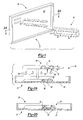
FIG. 1 is a perspective view of a seat back during application of a reinforcement; -
FIG. 2A illustrates a sectional view of the seat back ofFIG. 1 during application of the reinforcement; -
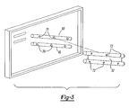
FIG. 2B illustrates a sectional view of the seat back ofFIG. 1 after application of the reinforcement; and -
FIG. 3 is a perspective view of an alternative seat back during application of an alternative reinforcement. - According to one aspect of the present invention, a seat back system having at least one reinforcement structure is provided, and particularly, a seat back having one or more reinforcement structures that include a reinforcement formed of a secondary material. Preferably, the reinforcement extends along a main wall of the seat back panel. Advantageously, according to the present invention, a reinforcement of one desirable material (e.g., metal) may be easily attached (e.g., adhered) to seat backs of another different desirable material where attachments of such first and second materials may have previously been much more difficult.
- Referring to
Figs. 1, 2A and 2B , there is illustrated an improvedseat back system 20. Theseat back system 20 typically includes one or more panels 22 (e.g., a 60/40 split, a full seat or the like) that span a lateral distance of theseat back system 20. Preferably, each of the one ormore panels 22 include amain wall 26 and, preferably, only onemain wall 26 as will be further described below. - Each of the one or more panels of the seat back will include, one or more reinforcement structures (e.g., reinforcements, ribs, combinations thereof or the like) attached to and extending at least partially away from the wall. Preferably, the main wall of each panel spans substantially continuously between an entire periphery of the panel with the reinforcement structures extending substantially along the wall. It is preferable that the reinforcement structures include at least one reinforcement that is formed of a secondary material different than the wall. It is contemplated however that such a reinforcement may be formed of a similar or same material as the wall or seat back. As used herein, a secondary material refers to a material or combination of materials that is at least slightly compositionally different from the material of the seat back.
- The panels of the seat back may be formed of any suitable material, including but not limited to metal, plastic (including reinforced or unreinforced plastic), other composite material or otherwise. Preferably, at least one of the panels is plastic. More preferably, all of the panels are plastic (e.g., thermoplastic, thermoset or combination thereof).
- It is contemplated that a reinforcement structure according to the present invention may include one or more separately formed reinforcements of a material that differs in composition or form from the panels.
- The employment of microcellular foam plastics is also contemplated within the scope of the present invention. In accordance therewith, a gas/polymer solution is formed, and the solution is rendered thermodynamically unstable in order to nucleate microvoids. The growth of nuclei is then controlled as desired.
- It is possible to make seat back panels using art-disclosed techniques for the fabrication of the material selected. Thus, for example, the panels may be formed, molded, machined or otherwise configured to the desired shape. Where the panels are plastic, it is possible to use any suitable plastic fabrication technique including, without limitation, injection molding (including but not limited to external or internal gas injection molding), blow molding, compression molding, rotational molding, thermoforming, extruding, vacuum forming, foaming-in-place, or otherwise. One or more other fabrication techniques can also be employed such as insert molding, over-molding or a combination thereof. Accordingly, as can be appreciated, in one embodiment, hybrid seat assemblies can be fabricated, thereby taking advantage of the benefits of different respective materials and different respective fabrication techniques, and also advantageously permitting for the ability to design additional features.
- The present invention contemplates the use of the reinforcement structures for imparting additional rigidity, toughness or impact resistance to a seat back assembly, or otherwise locally modifying the bending moment of a structure.
- Examples of structures or patterns for reinforcement structures may include, without limitation, the "C" shape, "D" shape, "H" shape, "I" shape, "J" shape, "L" shape, "M" shape, "N" shape, "O" shape, "S" shape, "T" shape, "U" shape, "V" shape, "W" shape, "X" shape, "Y" shape, "Z" shape, curves (e.g. sinusoidal curves), zig zags, "+" shape, or the like.
- In one preferred embodiment, the reinforcement structures of the panels are reinforcements formed of a secondary material and attached to the seat back. The reinforcements of the panels for the seat back may be configured as desired for reinforcing the main wall of the seat back and such configuration may depend upon the design (e.g., shape, size, strength requirements or the like) of the seat back for any particular vehicle. For example, the reinforcements may be substantially planar or contoured and may be large or small and short or long depending upon the design of the seat back. Moreover, there may be as many or as few reinforcements as required or desired.
- In one highly preferred embodiment, the reinforcement structures may include one or more reinforcements such as ribs formed of an integral material. As an example, such ribs may be provided as solid or channel forming structures that are attached to the main wall of the seat back. Preferably, for channel forming ribs, such ribs are formed by gas assist injection molding as describe in commonly owned patent
application serial number 60/414,040 (filed September 27, 2002 - Referring again to
Figs. 1, 2A and 2B , there is illustrated theseat back system 20 includes at least onereinforcement structure 30 having areinforcement 32 attached to thepanel 22 of thesystem 20. Preferably, thereinforcement 32 is at least partially formed of a secondary material. - It is contemplated that the
reinforcement 32 may be formed in a variety of shapes and configurations. For example, thereinforcement 32 may be flat or contoured, elongated or stout, geometric or otherwise shaped depending upon the desired manner of applying thereinforcement 32 to the seat backsystem 20 and the manner of reinforcing desired. In the particular embodiment illustrated, thereinforcement 32 is provided as an elongate contoured strip having a length (L), a width (W) and a thickness (T). While the length, width and thickness are illustrated as substantially constant, these dimensions may be varied for different reinforcements and the dimensions may vary for a single reinforcement. - Generally, the numerical values for the dimensions of the
reinforcement 32 are not narrowly critical and can depend upon the distance or area over which areinforcement 32 is to span. However, it is typically desirable to maintain smaller dimensions and particularly a smaller thickness for maintaining lower weight for thereinforcement 32. Accordingly, the thickness is preferably less than about 5 mm, more preferably less than about 2 mm and even more preferably less than about 1 mm. It may also be preferable to form thereinforcement 32 with one or a plurality of voids (e.g., through-holes) for lowering the weight of thereinforcement 32. In such an embodiment, thereinforcement 32 may be substantially skeletal such that the voids defined in thereinforcement 32 occupy a greater volume that the secondary material of thereinforcement 32. - The
reinforcement 32 preferably includes a mating or correspondingsurface 36 that corresponds to (e.g., mirrors) a mating or correspondingsurface 40 of thepanel 22 of the seat backsystem 20, although not required. Thereinforcement 22 inFigs. 1-2B includes a pair ofribs 50 extending along the length (L) of thereinforcement 32 and aweb 52 interconnecting theribs 50 thereby forming thesurface 36 to include aplanar portion 54 and a pair ofchannels 56. For correspondence,mating surface 40 of thepanel 22 of the seat backsystem 20 defines a pair ofreinforcements 60 shown as ribs configured to extend into thechannels 52 and aplanar portion 64 configured to fit substantially flush against theplanar portion 54 of thereinforcement 32. - The secondary material of the
reinforcement 32 may be selected from a variety of materials such as polymers, glass, metals, fiber-based materials (e.g., glass, carbon fiber, aramid metal or otherwise), woven materials, unwoven materials, combinations thereof or the like. In one preferred embodiment, the secondary material is at least partially or substantially entirely formed of one or more metals such as aluminum, iron, tungsten, magnesium, steel, tin, copper, titanium, combinations thereof or the like. According to one preferred embodiment, the secondary material of the reinforcement is substantially entirely low carbon steel. - The
reinforcement 32 may be formed using a variety of techniques. For example, thereinforcement 32 may be roll formed, cast, stamped or the like. The reinforcement may also be molded, extruded or the like. - Suitably the panel can comprise a plastic molding. The plastics material preferably comprises a homopolymer, for example a polyolefin, a polyamide, a polyphenylene oxide and polystyrene, or a copolymer, for example a polyalkylene terephthalate, having a low surface energy although higher surface energies are also possible.
- Preferred plastics materials include polypropylene, polyamide, polyamide alloys, polyphenylene oxide polymers, polyphenylene oxide alloys, polystyrene polymers, polystyrene alloys, polybutylene terephthalate polymers and polybutylene terephthalate alloys. The plastics material may contain fibre, for example short glass fibre, long glass fibre, short natural fibre or long natural fibre.
- Especially preferred plastics materials include short glass fibre filled polypropylene, long glass fibre filled polypropylene, glass filled polyamide and glass filled polyamide alloys.--Plastics materials which are especially preferred for use in bumper systems as the EAU include unfilled polypropylene, talc filled polypropylene, mineral filled polypropylene]
- In certain preferred embodiments, the polymeric materials may include fibers for additional strength. Although it is contemplated that fibers of various sizes (e.g., lengths) may be employed, advantageously, it has been found that relatively long glass fibers add a relatively high degree of strength. Thus, in preferred embodiments, a polymeric material such as ABS, PCABS, polypropylene, SMA (styrene maleic anhydride), PPO (polyphenylene oxide) or another suitable plastic is filled with glass fibers having an average length of approximately greater than 2 mm, more preferably greater than about 4mm even more preferably greater than about 6 mm and most preferably between about 8 mm and 20 mm.
- The
reinforcement 32 may be attached to or integrated with the rest of the seat backsystem 20 using a variety of integration or attachment techniques for forming thereinforcement structure 30. For example, mechanical fasteners such as screws, clips, rivets combinations thereof or the like may be employed. Alternatively, thereinforcement 32 may be integrated with the seat backsystem 20 by molding at least a portion of the seat backsystem 20 about thereinforcement 32 according to one of the molding techniques described herein. As other alternatives heat staking, vibrational welding, sonic welding, combinations thereof or the like may be used to attach thereinforcement 32 to thepanel 22. - In one embodiment, the
reinforcement 32 is adhered to thepanel 22 of the seat backsystem 20 with an adhesive 66. Preferably, the adhesive 66 is applied to one or both of the mating surfaces 40, 36 respectively of thepanel 22 and thereinforcement 32. Thereafter, thesurfaces surfaces reinforcement 32 and thepanel 22 are attached to each other. Of course, it is contemplated that the adhesive 66 may be applied to any surfaces of thereinforcement 32 or the seat backsystem 20 for adhering thereinforcement 32 to the seat backsystem 20. - Any suitable adhesive may be employed in the present invention. Preferably, the adhesive 66 is compatible with (i.e., capable of adhering to) the material of the
panel 22 and the secondary material of thereinforcement 32. If, however, the adhesive 66 is incompatible with one of these materials, it may be desirable to treat the surface[s] of thepanel 22 or thereinforcement 32 formed of the incompatible material. Exemplary treatments include the application of primer, exposure to plasma, combinations thereof or the like. - In one embodiment, the adhesive is a urethane based adhesive, and more preferably a urethane adhesive (e.g., a polyurethane adhesive). Alternatively, the adhesive may include a functional component selected from methyl methacrylate (MMA), acrylonitrile butadiene styrene (ABS), polycarbonate (PC), or a mixture thereof (e.g. PC-ABS). In a further alternative embodiment the adhesive is a silane adhesive, a silicone adhesive or a mixture thereof. In yet another embodiment, the adhesive is an acrylic adhesive. The adhesive may also be epoxy based. It may include polyolefinics, styrenics, acrylics or mixtures thereof. In yet another embodiment, a preferred adhesive includes alkyl borane. Examples of suitable adhesives are disclosed in commonly owned
U.S. Patent No. 09/466,321 (filed December 17, 1999 20020058764 and20030001410 expressly incorporated herein by reference for all purposes. Any such adhesive may include suitable performance modifiers including art disclosed tackifiers, elastomers, impact modifiers, or the like. - In one highly preferred embodiment, a two part, organoborane/amine complex adhesive or other adhesive is employed for adhesively securing the
reinforcement 32 to thepanel portion 22. Advantageously, it has been found that the adhesive is compatible with metal (e.g., steel) and plastic, particularly polypropylene. As such, the adhesive may be used for attaching thereinforcement 32, when formed of metal, to the seat backsystem 20, when formed of plastic or polypropylene, without having to treat any surfaces of thereinforcement 32 or seat backsystem 20 prior to adhesion. - An especially preferred embodiment of the invention provides a panel made of a molded glass filled polypropylene and/or glass filled polyamide having a surface energy of less than 45 mJ/m2, and a reinforcement made from steel, zinc and/or aluminium. As such, the adhesive which is preferably capable of bonding to a substrate having a surface energy of less than 45 mJ/m2 is disposed between at least part of the corresponding surfaces so as to bond them together, the adhesive being derived from a polymerizable composition comprising
- i) an organoborane/amine complex;
- ii) one or more of monomers, oligomers or polymers having olefinic unsaturation which is capable of polymerization by free radical polymerization; and, optionally
- iii) a compound which causes the said complex to disassociate so as to release the borane to initiate polymerization of one or more of monomers, oligomers or polymers having olefinic unsaturation.
- Additional especially preferred aspects of the invention are a method of making the automobile assembly referred to in the preceding paragraph and use of an adhesive described in that paragraph in fabricating the assembly described in it.
- Adhesives and polymerizable compositions disclosed in
International Patent Application No. PCT/US00/33806 are especially preferred for use in the present invention to bond the structural member and reinforcing member together. - The amines used to complex the organoborane compound can be any amines which complex the organoborane and which can be decomplexed when exposed to a decomplexing agent. Preferred amines include the primary or secondary amines or polyamines containing primary or secondary amine groups, or ammonia, as disclosed in
Zharov U.S. Pat. No. 5,539,070 at column 5 lines 41 to 53, incorporated herein by reference,Skoultchi U.S. Pat. No. 5,106,928 at column 2 line 29 to 58 incorporated herein by reference, andPocius U.S. Pat. No. 5,686,544 column 7, line 29 to Column 10line 36 incorporated herein by reference; moroethanolamine, secondary dialkyl diamines or polyoxyalkylenepolyamines; and amine terminated reaction products of diamines and compounds having two or more groups reactive with amines as disclosed inDeviny U.S. Pat. No. 5,883,208 at column 7line 30 to column 8line 56, incorporated herein by reference. With respect to the reaction products described in Deviny the preferred diprimary amines include alkyl diprimary amines, aryl diprimary amines, alkyaryl diprimary amines and polyoxyalkylene diamines; and compounds reactive with amines include compounds which contain two or more groups of carboxylic acids, carboxylic acid esters, carboxylic acid halides, aldehydes, epoxides, alcohols and acrylate groups. Preferred amines include n-octylamine, 1,6-diaminohexane (1,6-hexane diamine), diethylamine, dibutyl amine, diethylene triamine, dipropylene diamine, 1,3-propylene diamine (1,3-propane diamine), 1,2-propylene diamine, 1,2-ethane diamine, 1,5-pentane diamine, 1,12-dodecanediamine, 2-methyl-1,5-pentane diamine, 3-methyl-1,5-pentane diamine, triethylene tetraamine, diethylene triamine. Preferred polyoxyalkylene polyamines include polyethyleneoxide diamine, polypropyleneoxide diamine, triethylene glycol propylene diamine, polytetramethyleneoxide diamine and polyethyleneoxidecopolypropyleneoxide diamine. - In particular, the amine in the organoborane/amine complex is suitably selected from the group of amines having an amidine structural component; aliphatic heterocycles having at least one nitrogen in the heterocyclic ring wherein the heterocyclic compound may also contain one or more nitrogen atoms, oxygen atoms, sulphur atoms, or double bonds in the heterocycle; primary amines which in addition have one or more hydrogen bond accepting groups wherein there are at least two carbon atoms, preferably at least three carbon atoms, between the primary amine and the hydrogen bond accepting group, such that due to inter- or intramolecular interactions within the complex the strength of the B--N bond is increased; and conjugated imines.
- Preferred hydrogen bond accepting groups include the following: primary amines, secondary amines, tertiary amines, ethers, halogens, polyethers or polyamines. Heterocycle as used herein refers to a compound having one or more aliphatic cyclic rings of which one of the rings contains nitrogen. The amidines or conjugated imines may be straight or branched chain or cyclic.
- Desirably, the organoborane used in the complex is a trialkyl borane or an alkyl cycloalkyl borane. Preferably this borane corresponds to Formula 1:
B--(R1)3 Formula 1
wherein B represents boron; and R1 is separately in each occurrence a C1-10 alkyl, C3-10 cycloalkyl, or two or more of R1 may combine to form a cycloaliphatic ring. - Preferably R1 is C1-4 alkyl, even more preferably C2-4 alkyl and most preferably C3-4 alkyl. Among preferred organoboranes are tri-ethyl borane, triisopropyl borane and tri-n-butylborane.
- In a preferred embodiment, the amine part of the complex comprises a compound having a primary amine and one or more hydrogen bond accepting groups, wherein there are at least two carbon atoms, preferably at least about three, between the primary amine and hydrogen bond accepting groups.
- Preferably, the amine corresponds to Formula 2:
NH2(CH2)b(C(R2)2)aX (2)
wherein R2 is separately in each occurrence hydrogen or a C1-10 alkyl or C3-10 cycloalkyl; X is hydrogen bond accepting moiety; a is an integer of 1 to 10; and b is separately in each occurrence an integer of 0 to 1, and the sum of a and b is from 2 to 10. - Preferably R2 is hydrogen or methyl.
- Preferably X is separately in each occurrence a hydrogen accepting moiety and, when the hydrogen accepting moiety is an amine, it is preferably a tertiary or a secondary amine. More preferably X is separately in each occurrence --N(R2)e, --OR10, or a halogen wherein R8 is separately in each occurrence C1-10 alkyl, C3-10 cycloalkyl or --(C(R2)2)d--W; R10 is separately in each occurrence, C1-10 alkyl, C3-10 cycloalkyl, or --(C(R2)2)d--W; and e is 0, 1, or 2. More preferably X is--N(R8)2 or --OR10.
- Preferably, R8 and R10 are C1-4 alkyl or --(C(R1)2)d--W, more preferably C1-4 alkyl and most preferably methyl. W is separately in each occurrence hydrogen or C1-10 alkyl or X and more preferably hydrogen or C1-4 alkyl.
- Preferably, a is about 1 or greater and more preferably 2 or greater. Preferably a is about 6 or less, and most preferably about 4 or less. Preferably, b is about 1. Preferably, the sum of a and b is an integer about 2 or greater and most preferably about 3 or greater. Preferably the sum of a and b are about 6 or less and more preferably about 4 or less. Preferably d is separately in each occurrence an integer of 1 to 4, more preferably 2 to 4, and most preferably 2 to 3.
- Among preferred amines corresponding to Formula 2 are dimethylaminopropyl amine, methoxypropyl amine, dimethylaminoethylamine, dimethylaminobutylamine, methoxybutyl amine, methoxyethyl amine, ethoxypropylamine, propoxypropylamine, amine terminated polyalkylene ethers (such as trimethylolpropane tris(poly(propyleneglycol), amine terminated)ether), aminopropylmorpholine, isophoronediamine, and aminopropylpropanediamine.
- In another embodiment, the amine may be an aliphatic heterocycle having at least one nitrogen in the heterocycle. The heterocyclic compound may also contain one or more of nitrogen, oxygen, sulfur or double bonds. In addition, the heterocycle may comprise multiple rings wherein at least one of the rings has a nitrogen in the ring. Preferred compounds of this type include morpholine, piperidine, pyrolidine, piperazine, 1,3,3 trimethyl 6-azabicyclo[3,2,1] octane, thiazolidine, homopiperazine, aziridine, 1,4-diazabicylo[2.2.2]octane (DABCO), 1-amino-4-methylpiperazine, and 3-pyrroline.
- In yet another embodiment, the amine which is suitably complexed with the organoborane is an amidine. Any compound with amidine structure wherein the amidine has sufficient binding energy as described hereinbefore with the organoborane, may be used. Among preferred amidines are 1,8 diazabicyclo[5,4]undec-7-ene; tetrahydropyrimidine; 2-methyl-2-imidazoline; and 1,1,3,3-tetramethylguanidine.
- In a further embodiment, the amine which is complexed with the organoborane is suitably a conjugated imine. Any compound with a conjugated imine structure, wherein the imine has sufficient binding energy with the organoborane as described in
International Patent Application No. PCT/US00/33806 may be used. The conjugated imine can be a straight or branched chain imine or a cyclic imine. Among preferred conjugated imines are 4-dimethylaminopyridine; 2,3-bis(dimethylamino)cyclopropeneimine; 3-(dimethylamine)acroleinimine; 3-(dimethylamino)methacrole- inimine. - Preferably the molar ratio of amine compound to organoborane compound is from 1.0:1.0 to 3.0:1.0. Below the ratio of about 1.0:1.0 there may be problems with polymerization, stability of the complex and adhesion. Greater than about a 3.0:1.0 ratio may be used although there may not be additional benefit from using a ratio greater than about 3.0:1.0. If too much amine is present, this may negatively impact the stability of the adhesive or polymer compositions. Preferably the molar ratio of amine compound to organoborane compound is from 2.0:1.0 to 1.0:1.0.
- The organoborane amine complex may be readily prepared using known techniques, for example as described or referred to in International Patent Application No.
PCT/US00/33806 . - Preferably, the polymerizable material comprises acrylate and/or methacrylate based compounds. Especially preferred acrylate and methacrylate compounds include methylmethacrylate, butylmethacrylate, ethylhexylmethacrylate, isobornylmethacrylate, tetrahydrofurfuryl methacrylate, and cyclohexylmethylmethacrylate.
- The polymerizable composition may further comprise an effective amount of a compound that is reactive with an amine so as to liberate the organoborane so as to initiate polymerization (a disassociating agent). Desirable amine reactive compounds are those materials that can readily form reaction products with amines at or below and more preferably at room temperature so as to provide a composition that can be generally easily used and cured under ambient conditions. General classes of these compounds include acids, aldehydes, isocyanates, acid chlorides, sulphonyl chlorides, mixtures thereof and the like. Preferred amine reactive compounds are acids, especially Bronsted and Lewis acids and those described in
U.S. Pat. No. 5,718,977 and, more desirably acrylic acid and methacrylic acid. - In the polymerizable composition, suitably at least 20% by weight, preferably at least 30% by weight and especially at least 40% by weight of the composition comprises the polymerizable component. Independently, the polymerizable component is suitably present at a level not exceeding 95%, preferably not exceeding 90% and especially not exceeding 85% by weight of the composition.
- Suitably, the organoborane/amine complex is present at a level of at least 0.2%, preferably at least 1% and more preferably at least 2% by weight of the composition. Independently, the complex is suitably present at a level not exceeding 8%, preferably not exceeding 6% and especially not exceeding 4% by weight of the composition.
- If present, the disassociating compound is present at a level of at least 1%, preferably at least 1.5% and more preferably at least 2% by weight of the composition. Independently, the disassociating compound is suitably present at a level not exceeding 8%, preferably not exceeding 6% and especially not exceeding 4% by weight of the composition.
- The adhesive to be employed in the present invention suitably is capable of providing a bond between a 30% glass filled polypropylene structural member and the reinforcing member without the structural member having been subjected to any surface treatment when tested in accordance with the procedure set out in ASTM D1002. Preferably, the adhesive provides a bond when tested under this regime including in addition being subjected to thermal cycling and high humidity. Thermal cycling in this context suitably includes cycling over a range from -40.degree. C. to greater than 120.degree. C. Humidity levels can vary from dry to fully saturated.
- The adhesive may be used in the manner set out in
International Patent Application No. PCT/US00/33806 . Optionally, further components may be included as additives in the composition. Suitable additives include those set out in International Patent Application No.PCT/US00/33806 . - The assembly suitably is able to withstand exposure to heat at a temperature of 100°C. and suitably at up to 120°C. or more. Further, the assembly desirably should also be able to withstand loads applied during production and also imposed in use, for example by slamming the bonnet, application of load to the bonnet latch and vibration and fatigue during use due to displacement from the road surface. The amount and location of adhesive is suitably selected having regard to the design and structure of the automobile to which the application applies.
- Once the adhesive 66 and the
reinforcement 32 have been applied to the seat backsystem 20, the adhesive 66 will typically require some amount of time to cure (e.g., part cure, full cure, cure on demand, air cure, heat cure, moisture cure, chemical cure, light cure, or the like) for securing thereinforcement 32 to thepanel 26. Preferably, the adhesive cures at about room temperature (e.g., between about 20 °C to about 30 °C), but may be exposed to elevated or lowered temperatures for accelerating or slowing cure times. During cure, it may be desirable to apply fasteners (e.g., push-pins, clips or the like) to thereinforcement 32 for securing thereinforcement 32 to the seat backsystem 20. Such fasteners may be removable or may be intended to assist in securing thereinforcement 32 to the seat backsystem 20 during use of the seat backsystem 20 as well. - Generally, it is desirable for the adhesive to exhibit a reasonable amount of post-cure ductility. Preferably, the adhesive exhibits ductility that is as high as the ductility of material that forms the
reinforcement 32 or the material that forms the seat backsystem 20 orpanel 22, whichever ductility is lower. More preferably, however, the adhesive 66 exhibits ductility that is as high as the ductility of material that forms thereinforcement 32 or the material that forms the seat backsystem 20, whichever ductility is higher. - Advantageously, it has been found that lower cycle times for forming seat backs with reinforcement structure have a reinforcement formed of secondary material can be achieved according to the present invention. For example, these seat back systems can be formed with cycle times of less than a minute, more preferably less than about 40 seconds, even more preferably less than about 30 seconds and still more preferably less than about 20 seconds.
- In the embodiment depicted in
Figs. 1-2B , thereinforcement 32 is attached to a back side of the seat back system 20 (i.e., a side intended to face away from a passenger being supported by the seat back). However, one or more reinforcement structures having a reinforcement such as that shown may be located in a variety of locations on or within the seat back system. One or more additional of these reinforcement structures may be located on the back side of a seat back panel. One or more of these reinforcements may be located on the front side or may be integrated within a seat back panel. As another alternative, one or more these reinforcements may extend along the peripheral edges of the seat back panel. It is also contemplated that one or more of these reinforcements may extend across the seat back panel either laterally, longitudinally, horizontally, vertically, diagonally or combinations thereof. - In the embodiment depicted, the
reinforcement 32 is attached to the integral reinforcement of the seat backsystem 20. However, reinforcements such as thereinforcement 32 shown may also be placed within openings (e.g., cavities or through-holes) or upon substantially planar surfaces. - A seat back panel, a reinforcement or both according to the present invention may include one or more protrusions for assisting in locating the reinforcement relative to the seat back, for assisting in attaching the reinforcement to the seat back panel. Preferably, such protrusions are configured to be inserted in corresponding openings (e.g., cavities or through-holes), which may be formed in either the reinforcement, the seat back panel or both. In
Fig. 3 , a plurality ofprotrusions 70 extend from theribs 60 and theprotrusions 70 are configured for insertion into through-holes 72 formed in thereinforcement 32. - The design and location of each reinforcement structure or pattern fabricated in the seat back may be optimized for each individual application, taking into account some or all of the following criteria. For each application, the skilled artisan will appreciate that the specific reinforcement structure employed is configured to help minimize the bending or hinge effect caused by loads resulting from rapid deceleration or acceleration of a vehicle in the presence of a passenger or cargo behind a seat (e.g., that which experienced by a top mounted center shoulder belt, top mounted child seat anchors, and luggage intrusion). For instance, in one preferred embodiment, the reinforcement structure and pattern selected generally is one that will position a portion of the reinforcement structure having a higher bending moment in a position generally perpendicular to the torsional bending diagonal plane.
- In addition to the foregoing, it is contemplated the seat back system of the present invention may be employed in a front seat, a rear seat, a folding seat or the like. It is also contemplated the system may be configured to accommodate a child safety seat tether, a rear center shoulder belt or the like. Moreover, the system may be configured to meet predetermined standards (e.g., strength standards). A further discussion of such seats, tethers, belt and standards can be found in
U.S. Patent Application Serial No. 60/414,040 , already incorporated herein by reference. - The skilled artisan will recognize that although the seating system of the present invention has been described in relation to automotive seating, the system may also be used for other seats such as airplane and bus seats or auditorium and stadium seats.
- The foregoing discussion discloses and describes merely exemplary embodiments of the present invention. One skilled in the art will readily recognize from such discussion and from the accompanying drawings and claims, that various changes, modifications and variations can be made therein without departing from the scope of the following claims. In particular regard to the various functions performed by the above described components, assemblies, devices, compositions, etc., the terms used to describe such items are intended to correspond, unless otherwise indicated, to any item that performs the specified function of the described item, even though not necessarily structurally equivalent to the disclosed structure. In addition, while a particular feature of the invention may have been described above with respect to only one of the embodiments, such feature may be combined with one or more other features of other illustrated embodiments.
Claims (19)
- A method of forming an automotive seatback system (20), comprising:providing a first panel (22), configured to extend laterally across at least a portion of an automotive vehicle, the first panel being defined by an outer periphery and having a main wall that substantially continuously spans between the entirety of the periphery;providing a reinforcement (32) positioned upon the first panel (22) wherein:i) the first panel (22) is formed of a plastic material, the first panel having at least one corresponding surface;ii) the reinforcement (32) is formed of a secondary material different from the plastic material of the first panel (22), the reinforcement having at least one corresponding surface; and adhering the corresponding surface of the reinforcement (32) to the corresponding surface of the first panel (22) with an adhesive, such that the reinforcement (32) extends substantially along the main wall laterally, vertically or both.
- A method according to claim 1 wherein the at least one corresponding surface of the reinforcement or the at least one corresponding surface of the first panel is a low energy surface and wherein the adhesive is capable of bonding to a low energy surface.
- A method according to claim 2 wherein the low energy surface is a plastic having a surface energy of less than 45 mJ/m2.
- A method according to claim 1 or 2 in which the plastic material comprises a polymer selected from a polyolefin, a polystyrene, a polyamide, a polybutylene tare phthalate, an acrylonitrile butadiene styrene, a polycarbonate or a combination thereof.
- A method according to claim 4 in which the plastics material comprises a fibre.
- A method according to claim 5 in which the fibre is selected from short glass fibre, long glass fibre, short natural fibre or long natural fibre.
- A method according to claims 1, 2 or 3 in which the plastics material is selected from short glass fibre filled polypropylene, long glass fibre filled polypropylene, glass filled polyamide and glass filled polyamide alloys.
- A method according to any of claims 1-7 wherein the reinforcement and it corresponding surface is made of a metal selected from steel, aluminium or a combination thereof.
- A method according to any of daims 1-8 further comprising applying the adhesive directly to the corresponding surface of the panel without treatment or priming of the said corresponding surface of the panel.
- A method according to any of claims 1-9 wherein the adhesive comprises an organoborane/amine complex and one or more of monomers, oligomers or polymers having olefinic unsaturation which is capable of polymerization by free radical polymerization.
- A method according to claim 10 In which the adhesive further comprises a compound which causes the complex to disassociate so as to release the organoborane to initiate polymerization of one or more of monomers, oligomers or polymers having olefinic unsaturation.
- A method according to claim 10 wherein the amine part of the organoborane/amine complex is selected from the group of amines having an amidine structural component; aliphatic heterocycles having at least one nitrogen in the heterocyclic ring; primary amines which in addition have one or more hydrogen bond accepting groups wherein there are at least two carbon atoms between the primary amine and the hydrogen bond accepting group; and conjugated imines.
- A method according to claim 10 wherein the amine is selected from dimethylaminopropyl amine, methoxypropyl amine, dimethylaminoethylamine, dimethylaminobutylamine, methoxybutyl amine, methoxyethyl amine, ethoxypropylamine, propoxypropylamine, amino terminated polyalkylene ethers (such as trimethylolpropane trls(poly(propylenegiycol), amine terminated)ether), aminopropylmorpholine, isophoronediamine, and aminopropylpropanediamine.
- A method according to claim 10 wherein the organoborane part of the organoborane/amine complex is selected from a trialkyl borane and an alkyl cycloalkyl borane.
- A method according to any of claims 1-14 wherein the at least one corresponding surface of the reinforcement defines one or more contours corresponding to one or more contours defined by the at least one corresponding surface of the panel.
- A method according to claim 15 wherein the one or more contours of the reinforcement are at least partially defined by ribs or cavities and the one or more contours of the panel are defined by ribs or cavities.
- A method according to any of claims 1-16 wherein the panel is formed by a process selected from compression molding, injection molding or blow molding.
- A method according to any of claims 1-17 wherein the cycle time for formation of the seatback system is less than 40 seconds.
- A method according to any of claims 1-18 wherein the cycle time for formation of the seatback system is less than 30 seconds.
Applications Claiming Priority (5)
| Application Number | Priority Date | Filing Date | Title |
|---|---|---|---|
| US755897 | 1991-09-06 | ||
| US44711803P | 2003-02-13 | 2003-02-13 | |
| US447118P | 2003-02-13 | ||
| US10/755,897 US7250091B2 (en) | 2003-02-13 | 2004-01-13 | Method of forming a seating system |
| PCT/US2004/003940 WO2004074036A1 (en) | 2003-02-13 | 2004-02-10 | Seating system and method of forming same |
Publications (3)
| Publication Number | Publication Date |
|---|---|
| EP1597109A1 EP1597109A1 (en) | 2005-11-23 |
| EP1597109B1 EP1597109B1 (en) | 2008-07-02 |
| EP1597109B9 true EP1597109B9 (en) | 2008-11-05 |
Family
ID=32912251
Family Applications (1)
| Application Number | Title | Priority Date | Filing Date |
|---|---|---|---|
| EP20040709933 Expired - Lifetime EP1597109B9 (en) | 2003-02-13 | 2004-02-10 | Method of forming a seat system |
Country Status (10)
| Country | Link |
|---|---|
| US (2) | US7250091B2 (en) |
| EP (1) | EP1597109B9 (en) |
| JP (1) | JP2006520215A (en) |
| KR (1) | KR101059341B1 (en) |
| AT (1) | ATE399676T1 (en) |
| BR (1) | BRPI0407231A (en) |
| CA (1) | CA2513118A1 (en) |
| DE (1) | DE602004014730D1 (en) |
| ES (1) | ES2309498T3 (en) |
| WO (1) | WO2004074036A1 (en) |
Families Citing this family (31)
| Publication number | Priority date | Publication date | Assignee | Title |
|---|---|---|---|---|
| KR100733134B1 (en) * | 2005-04-29 | 2007-06-28 | 주식회사 엘지화학 | Frame panel |
| DE102006033156A1 (en) * | 2006-07-18 | 2008-01-24 | Keiper Gmbh & Co.Kg | Structure of a vehicle seat |
| US7842146B2 (en) | 2007-01-26 | 2010-11-30 | Dow Global Technologies Inc. | Ultrasonic energy for adhesive bonding |
| KR100900568B1 (en) * | 2007-10-15 | 2009-06-02 | 주식회사 케이디에스인텍 | Wood mold having airventchannel and airhole |
| DE102008036646A1 (en) * | 2007-10-26 | 2009-04-30 | C. Rob. Hammerstein Gmbh & Co. Kg | Frame side part of a vehicle seat |
| US20090189321A1 (en) | 2008-01-29 | 2009-07-30 | Dow Global Technologies Inc. | Thermoplastic composition and use for large parison blow molding applications |
| JP5632294B2 (en) | 2008-02-08 | 2014-11-26 | スリーエム イノベイティブ プロパティズ カンパニー | Composite material |
| US8742050B2 (en) | 2008-03-28 | 2014-06-03 | Henkel US IP LLC | Two part hybrid adhesive |
| US9217066B2 (en) * | 2008-03-31 | 2015-12-22 | Ford Global Technologies, Llc | Structural polymer insert and method of making the same |
| DE102008020290B4 (en) * | 2008-04-22 | 2015-02-19 | Johnson Controls Gmbh | Structural part and vehicle seat with a backrest |
| EP2296938B1 (en) * | 2008-05-28 | 2013-08-28 | Styron Europe GmbH | Improved vehicular seat back assembly |
| WO2010024817A1 (en) | 2008-08-29 | 2010-03-04 | Lear Corporation | Vehicle seat frame and method of making |
| DE102008055103A1 (en) | 2008-12-22 | 2010-07-01 | Sitech Sitztechnik Gmbh | seat structure |
| CN103097189A (en) | 2010-06-07 | 2013-05-08 | 思迪隆欧洲有限公司 | Seating assembly with a blow molded seat back |
| US9180791B2 (en) | 2010-12-01 | 2015-11-10 | Salflex Polymers Limited | Seat-back with anchorage bar |
| KR20130142190A (en) | 2011-04-15 | 2013-12-27 | 존슨 컨트롤스 게엠베하 | Reinforced structural element made of plastic, in particular in the vehicle interior design field |
| EP2911911A4 (en) | 2012-10-23 | 2016-10-12 | Lear Corp | Thoracic region comfort seating system |
| US9004606B2 (en) | 2013-04-17 | 2015-04-14 | H.O. Bostrom Company, Inc. | Emergency vehicle seat with integrated seat belt and height adjustable webbing guide |
| KR101529246B1 (en) * | 2013-11-20 | 2015-06-16 | 한화첨단소재 주식회사 | Rod enhanced type seat back frame |
| KR101537862B1 (en) * | 2013-11-27 | 2015-07-17 | 롯데케미칼 주식회사 | Hybrid seat frame for vehicle |
| US9757898B2 (en) | 2014-08-18 | 2017-09-12 | Lord Corporation | Method for low temperature bonding of elastomers |
| US11259637B2 (en) | 2015-04-13 | 2022-03-01 | Steelcase Inc. | Seating arrangement |
| WO2016168185A1 (en) | 2015-04-13 | 2016-10-20 | Steelcase Inc. | Seating arrangement |
| US10194750B2 (en) | 2015-04-13 | 2019-02-05 | Steelcase Inc. | Seating arrangement |
| US10259353B2 (en) | 2015-04-23 | 2019-04-16 | Syntec Seating Solutions, Llc | School bus seat |
| CN105266450A (en) * | 2015-10-23 | 2016-01-27 | 珠海世锠金属有限公司 | Barstool manufacturing method |
| US10966527B2 (en) | 2017-06-09 | 2021-04-06 | Steelcase Inc. | Seating arrangement and method of construction |
| US10308203B2 (en) * | 2017-06-20 | 2019-06-04 | Ford Global Technologies, Llc | Stab proof back panel for law enforcement vehicle |
| US11109683B2 (en) | 2019-02-21 | 2021-09-07 | Steelcase Inc. | Body support assembly and method for the use and assembly thereof |
| US11424105B2 (en) * | 2019-08-05 | 2022-08-23 | Hitachi High-Tech Corporation | Plasma processing apparatus |
| US11357329B2 (en) | 2019-12-13 | 2022-06-14 | Steelcase Inc. | Body support assembly and methods for the use and assembly thereof |
Family Cites Families (106)
| Publication number | Priority date | Publication date | Assignee | Title |
|---|---|---|---|---|
| US2657739A (en) * | 1949-12-12 | 1953-11-03 | Thad B Mccarty | Basic structure for auxiliary seats or the like |
| US3054643A (en) * | 1960-07-18 | 1962-09-18 | Finkel Outdoor Prod | Chairs with snap-on slats and such slats |
| US3171691A (en) * | 1963-07-17 | 1965-03-02 | Ford Motor Co | Seat construction |
| US3245715A (en) * | 1964-09-08 | 1966-04-12 | Jules C Gits | Molded articles and methods of making same |
| US3523710A (en) * | 1968-07-11 | 1970-08-11 | American Seating Co | Safety vehicle seat |
| US3638997A (en) * | 1970-03-04 | 1972-02-01 | Scott N Shapiro | Temporary seat supported by spaced-apart chairs |
| US3712614A (en) * | 1970-07-17 | 1973-01-23 | Cambridge Res & Dev Group | Swing seat |
| US3647260A (en) * | 1970-08-13 | 1972-03-07 | Gen Tire & Rubber Co | Replaceable seat insert and process of making |
| US3669496A (en) * | 1970-12-03 | 1972-06-13 | American Desk Mfg Co | Chair and seat and back unit therefor |
| US3797887A (en) * | 1971-06-28 | 1974-03-19 | American Seating Co | Seat for urban mass transit vehicles |
| US3942836A (en) * | 1974-04-22 | 1976-03-09 | Steelcase Inc. | Chair |
| US4123105A (en) * | 1975-10-29 | 1978-10-31 | Interroyal Corporation | Chair construction |
| US4065182A (en) * | 1976-08-30 | 1977-12-27 | General Motors Corporation | Cushion retention for a vehicle seat |
| US4088367A (en) * | 1977-06-20 | 1978-05-09 | Rohr Industries, Inc. | Vehicle seat assembly |
| US4133579A (en) * | 1977-08-29 | 1979-01-09 | American Desk Manufacturing Co. | Stadium, gymnasium or like chair |
| US4246734A (en) * | 1978-10-18 | 1981-01-27 | K & M Plastics Inc. | Fold down multi-purpose vehicle seat back core with inmolded metal reenforcing member |
| US4142757A (en) * | 1977-10-27 | 1979-03-06 | K & M Plastics, Inc. | Fold down multi-purpose vehicle seat back core or the like automotive structural member |
| FR2420424A1 (en) | 1978-03-21 | 1979-10-19 | Permali Sa | Timber-reinforced moulded fibreboard panels for vehicle bench seats - minimise wt. and acoustic drumming c.f. use of pressed steel panels |
| JPS55150348A (en) * | 1979-05-11 | 1980-11-22 | Mitsui Petrochemical Ind | Seat |
| JPS56120319A (en) * | 1980-02-27 | 1981-09-21 | Showa Denko Kk | Core material of synthetic resin for sheet of vehicle and its manufacture |
| JPS58145410A (en) * | 1982-02-22 | 1983-08-30 | Aida Eng Ltd | Forming method of plastic material by mechanical press |
| JPS58168252U (en) * | 1982-05-06 | 1983-11-09 | トヨタ自動車株式会社 | car rear seat |
| DE3222505C2 (en) * | 1982-06-16 | 1986-04-10 | Keiper Recaro GmbH & Co, 7312 Kirchheim | Backrest for vehicle seats |
| JPS6024917A (en) | 1983-07-20 | 1985-02-07 | Tokyo Seat Kk | Manufacture of head rest cover |
| JPS6024918A (en) | 1983-07-20 | 1985-02-07 | Tokyo Seat Kk | Manufacture of head rest cover |
| DE3337910A1 (en) * | 1983-10-19 | 1985-05-09 | Keiper Recaro GmbH & Co, 5630 Remscheid | VEHICLE SEAT |
| JPS61114835A (en) | 1984-11-09 | 1986-06-02 | Nissan Shatai Co Ltd | Blow molding apparatus |
| JPH03118Y2 (en) * | 1985-02-13 | 1991-01-07 | ||
| DE3513807A1 (en) * | 1985-04-17 | 1986-10-23 | Adam Opel AG, 6090 Rüsselsheim | STORAGE OR LOCKING DEVICE, IN PARTICULAR FOR PIVOTING MOTOR VEHICLE SEATS |
| DE3609591A1 (en) * | 1986-03-21 | 1988-01-21 | Grammer Sitzsysteme Gmbh | SEAT |
| FR2602654B1 (en) * | 1986-08-14 | 1988-11-25 | Peugeot Cycles | SEAT STRUCTURE, PARTICULARLY FOR SEAT WITH ADJUSTABLE BACK |
| CA1243930A (en) * | 1987-08-07 | 1988-11-01 | Roland Leblanc | Collapsible infant seat |
| DE3841532A1 (en) * | 1988-12-09 | 1990-06-13 | Bayer Ag | BACKREST SUPPORT STRUCTURE FOR A VEHICLE SEAT AND VEHICLE SEAT BACKREST WITH THIS BACKREST SUPPORT STRUCTURE |
| JPH02197435A (en) * | 1989-01-27 | 1990-08-06 | Kuraray Co Ltd | Seat shell |
| JPH0347728A (en) | 1989-07-14 | 1991-02-28 | Mazda Motor Corp | Blow molding method of resin molded item |
| DE3936418C1 (en) * | 1989-11-02 | 1990-10-31 | Keiper Recaro Gmbh & Co, 5630 Remscheid, De | |
| JP2526693Y2 (en) * | 1989-11-15 | 1997-02-19 | 株式会社東洋シート | Seat frame structure of vehicle seat |
| US5441331A (en) * | 1990-04-19 | 1995-08-15 | Concept Seating, Inc. | Seating assembly |
| JPH04317607A (en) * | 1991-04-16 | 1992-11-09 | Nhk Spring Co Ltd | Seat frame |
| US5106928A (en) * | 1991-04-29 | 1992-04-21 | National Starch And Chemical Investment Holding Corporation | Acrylic adhesive composition and organoboron initiator system |
| US5224756A (en) * | 1991-05-14 | 1993-07-06 | The United States Of America As Represented By The Director Of The National Security Agency | Integrated child seat for vehicle |
| US5253924A (en) * | 1991-06-11 | 1993-10-19 | Concept Analysis Corporation | Blow molded seat back with integral reinforcing member |
| US5133588A (en) * | 1991-06-14 | 1992-07-28 | Deere & Company | Seat assembly with integral fuel tank |
| US5282667A (en) * | 1991-12-20 | 1994-02-01 | Hoover Universal, Inc. | Vehicle seat assembly with integral child seat |
| DE4208150A1 (en) | 1992-03-13 | 1993-09-16 | Bayerische Motoren Werke Ag | Backrest frame for vehicle seat - uses crosspiece and diagonal strut to distribute effects of side loads. |
| US5855706A (en) * | 1992-04-21 | 1999-01-05 | Branson Ultrasonics Corporation | Simultaneous amplitude and force profiling during ultrasonic welding of thermoplastic workpieces |
| US5658408A (en) * | 1992-04-21 | 1997-08-19 | Branson Ultrasonics Corporation | Method for processing workpieces by ultrasonic energy |
| US5375914A (en) * | 1992-05-12 | 1994-12-27 | J. G. Furniture Systems, Inc. | Public seating chair |
| US5540479A (en) * | 1992-05-22 | 1996-07-30 | Thomas; Alan V. | Vehicle seats |
| US5280995A (en) * | 1992-11-13 | 1994-01-25 | Hoover Universal, Inc. | Vehicle seat assembly with rotating seat pack panel and integral child seat |
| FR2698832B1 (en) | 1992-12-08 | 1995-02-24 | Peugeot | Modular seat structure for a motor vehicle. |
| US5298587A (en) * | 1992-12-21 | 1994-03-29 | The Dow Chemical Company | Protective film for articles and method |
| US5433786A (en) * | 1993-08-27 | 1995-07-18 | The Dow Chemical Company | Apparatus for plasma enhanced chemical vapor deposition comprising shower head electrode with magnet disposed therein |
| US5437498A (en) * | 1994-02-22 | 1995-08-01 | Hoover Universal, Inc. | Vehicle seat with side bolster reinforcement |
| DE69427411T2 (en) * | 1994-02-22 | 2002-06-06 | Minnesota Mining & Mfg | POLYMERIZABLE COMPOSITION CONTAINS POLYMERIZATION INITIATOR SYSTEMS BASED ON ORGANOBORAN AMINE COMPLEXES |
| US5597205A (en) * | 1994-02-25 | 1997-01-28 | Concept Analysis Corporation | Energy absorbing restraint seat back recliner for application on a restraint safety seat |
| US5575533A (en) * | 1994-02-25 | 1996-11-19 | Concept Analysis Corp. | Blow molded seat frame with integral reinforcement |
| US5499859A (en) * | 1994-05-04 | 1996-03-19 | Steelcase, Inc. | Upholstery attachment device and upholstered article using same |
| JPH0838306A (en) * | 1994-07-29 | 1996-02-13 | Itoki Crebio Corp | Mounting device for outer shell frame for backrest of chair |
| SE503705C2 (en) * | 1994-10-25 | 1996-08-05 | Volvo Ab | Load-bearing structure for use in a vehicle body |
| US5704685A (en) * | 1994-12-27 | 1998-01-06 | Nhk Spring Co., Ltd. | Vehicle rear seat provided with child seat |
| US5621143A (en) * | 1995-04-14 | 1997-04-15 | Minnesota Mining And Manufacturing Company | Organoborane polyoxyalkylenepolyamine complexes and adhesive compositions made therewith |
| US5601334A (en) * | 1995-07-14 | 1997-02-11 | Hoover Universal, Inc. | Integrated child seat with detachable booster seat |
| US5686544A (en) | 1995-08-11 | 1997-11-11 | Minnesota Mining And Manufacturing Company | Organoborane polyamine complex initiator systems and polymerizable compositions made therewith |
| US5968431A (en) * | 1995-08-31 | 1999-10-19 | Chrysler Corporation | Soft touch cover and method of manufacture |
| DE19532412C2 (en) * | 1995-09-01 | 1999-09-30 | Agrodyn Hochspannungstechnik G | Device for surface pretreatment of workpieces |
| US5603550A (en) * | 1995-10-18 | 1997-02-18 | Douglas & Lomason Company | Vehicle seat interlock system |
| CN1106411C (en) * | 1995-11-07 | 2003-04-23 | 美国3M公司 | Initiator system and adhesive composition made therewith |
| US5984419A (en) * | 1995-11-27 | 1999-11-16 | Lear Corporation | Automotive seat back |
| US6027171A (en) * | 1995-11-27 | 2000-02-22 | Lear Corporation | Automotive modular seat frame assembly |
| US5840070A (en) * | 1996-02-20 | 1998-11-24 | Kriton Medical, Inc. | Sealless rotary blood pump |
| US5700054A (en) * | 1996-04-23 | 1997-12-23 | Lear Corporation | Vehicle seat assembly including integral child restraint seat |
| US5743593A (en) * | 1996-08-09 | 1998-04-28 | Lear Corporation | Vehicle seat with integral child seat |
| US5722732A (en) * | 1996-08-26 | 1998-03-03 | General Motors Corporation | Shoulder belt retractor with headrest support |
| US5713634A (en) * | 1996-09-30 | 1998-02-03 | Koike; Toshihisa | Seat back structure of vehicle seat |
| JP3314914B2 (en) | 1997-01-20 | 2002-08-19 | スズキ株式会社 | Automotive seat structure |
| US6059369A (en) * | 1997-05-01 | 2000-05-09 | Lear Corporation | Composite vehicle seat back frame and method of manufacturing thereof |
| US5895096A (en) * | 1997-04-10 | 1999-04-20 | Lear Corporation | Vehicle seat back assembly and method of making a vehicle seat back assembly |
| DE19728052A1 (en) | 1997-07-01 | 1999-01-07 | Basf Ag | Vehicle seat |
| US5951110A (en) * | 1997-10-17 | 1999-09-14 | Irwin Seating Company | Contoured plastic seat back |
| JP3290940B2 (en) | 1997-12-03 | 2002-06-10 | 本田技研工業株式会社 | Body frames for motorcycles, etc. |
| DE19800071A1 (en) * | 1998-01-02 | 1999-07-08 | Volkswagen Ag | Restraint with a seat belt |
| US6074004A (en) * | 1998-02-19 | 2000-06-13 | Carmichael; Donald Edwin | Seat back frame for absorbing energy |
| US6062649A (en) * | 1998-03-03 | 2000-05-16 | Steelcase Development Inc. | Chair back construction |
| JP2002511350A (en) | 1998-04-15 | 2002-04-16 | アールシーシー リージョナル コンパクト カー アーゲー | Structural components made of fiber reinforced thermoplastic |
| JP2000023777A (en) * | 1998-07-16 | 2000-01-25 | Daihatsu Motor Co Ltd | Seat back structure for automobile |
| US6149683A (en) * | 1998-10-05 | 2000-11-21 | Kriton Medical, Inc. | Power system for an implantable heart pump |
| US6079781A (en) * | 1998-10-13 | 2000-06-27 | Tilley; Jay M. | Ventilated child restraint seat |
| US6158984A (en) * | 1998-12-28 | 2000-12-12 | Kriton Medical, Inc. | Rotary blood pump with ceramic members |
| US6234772B1 (en) * | 1999-04-28 | 2001-05-22 | Kriton Medical, Inc. | Rotary blood pump |
| US6536844B2 (en) * | 1999-11-18 | 2003-03-25 | Moeller Marine Products | Blow-molded seat assembly and method of making same |
| US6286902B1 (en) * | 1999-12-10 | 2001-09-11 | Tachi-S Co. Ltd. | Seat back framework of seat |
| US6806330B1 (en) * | 1999-12-17 | 2004-10-19 | Dow Global Technologies Inc. | Amine organoborane complex polymerization initiators and polymerizable compositions |
| US6565152B2 (en) * | 1999-12-23 | 2003-05-20 | Transportation Seating, Inc. | Lightweight seat assembly for public transportation vehicle |
| US6328386B1 (en) * | 2000-01-11 | 2001-12-11 | Takata Seat Belts Inc. | Seat belt system |
| US6491346B1 (en) * | 2000-06-01 | 2002-12-10 | Dow Global Technologies, Inc. | Seating system and method for making the same |
| US20050168041A1 (en) * | 2000-10-04 | 2005-08-04 | Glance Patrick M. | Thin, double-wall molded seat frame system |
| FR2816262B1 (en) | 2000-11-09 | 2003-01-31 | Cera | PROCESS FOR THE PRODUCTION OF A TRIM ELEMENT |
| US20020144808A1 (en) * | 2001-04-04 | 2002-10-10 | Jones Bart R. | Adhesively bonded radiator assembly |
| US6543404B2 (en) * | 2001-04-04 | 2003-04-08 | Dow Global Technologies, Inc. | Adhesively bonded engine intake manifold assembly |
| GB0114684D0 (en) * | 2001-06-15 | 2001-08-08 | Dow Chemical Co | Automobile assembly |
| US6679558B2 (en) * | 2001-07-26 | 2004-01-20 | Lear Corporation | Integral blow-molded, steel reinforced automotive seating structure |
| US6733064B2 (en) * | 2001-08-10 | 2004-05-11 | Lear Corporation | Impact absorbing assembly for vehicle interior systems and seat backs |
| US6557929B2 (en) * | 2001-08-10 | 2003-05-06 | Lear Corporation | Impact absorbing assembly for automobile interior systems |
| CA2455500C (en) | 2001-08-15 | 2011-09-27 | Dow Global Technologies Inc. | Improved seating system |
| US6783184B2 (en) * | 2002-01-17 | 2004-08-31 | Bayer Polymers Llc | Molded article having a rigid support and a flexible hollow member |
-
2004
- 2004-01-13 US US10/755,897 patent/US7250091B2/en not_active Expired - Fee Related
- 2004-02-10 EP EP20040709933 patent/EP1597109B9/en not_active Expired - Lifetime
- 2004-02-10 DE DE200460014730 patent/DE602004014730D1/de not_active Expired - Lifetime
- 2004-02-10 BR BRPI0407231 patent/BRPI0407231A/en not_active IP Right Cessation
- 2004-02-10 ES ES04709933T patent/ES2309498T3/en not_active Expired - Lifetime
- 2004-02-10 CA CA 2513118 patent/CA2513118A1/en not_active Abandoned
- 2004-02-10 KR KR1020057014775A patent/KR101059341B1/en not_active IP Right Cessation
- 2004-02-10 AT AT04709933T patent/ATE399676T1/en not_active IP Right Cessation
- 2004-02-10 JP JP2006503473A patent/JP2006520215A/en active Pending
- 2004-02-10 WO PCT/US2004/003940 patent/WO2004074036A1/en active Application Filing
-
2007
- 2007-07-25 US US11/782,803 patent/US20080011429A1/en not_active Abandoned
Also Published As
| Publication number | Publication date |
|---|---|
| US20080011429A1 (en) | 2008-01-17 |
| US20040194877A1 (en) | 2004-10-07 |
| WO2004074036A1 (en) | 2004-09-02 |
| DE602004014730D1 (en) | 2008-08-14 |
| JP2006520215A (en) | 2006-09-07 |
| ATE399676T1 (en) | 2008-07-15 |
| CA2513118A1 (en) | 2004-09-02 |
| KR101059341B1 (en) | 2011-08-24 |
| EP1597109A1 (en) | 2005-11-23 |
| ES2309498T3 (en) | 2008-12-16 |
| EP1597109B1 (en) | 2008-07-02 |
| KR20050093864A (en) | 2005-09-23 |
| BRPI0407231A (en) | 2006-01-31 |
| US7250091B2 (en) | 2007-07-31 |
Similar Documents
| Publication | Publication Date | Title |
|---|---|---|
| EP1597109B9 (en) | Method of forming a seat system | |
| US20070295453A1 (en) | Instrument Panel Assembly and Method of Forming Same | |
| CA2450647C (en) | Automobile assembly | |
| KR100923359B1 (en) | Improved seating system | |
| US20070284076A1 (en) | Modular assembly for a vehicle | |
| EP1564067A1 (en) | Improved seating system | |
| WO2008121754A1 (en) | Foam reinforced vehicular seating system | |
| US20040238114A1 (en) | Air bag system and method of forming the same | |
| US20100270846A1 (en) | Seating | |
| WO2009006142A1 (en) | Vehicle bumper fascia applique system | |
| CN100427336C (en) | Seating system and method of forming same |
Legal Events
| Date | Code | Title | Description |
|---|---|---|---|
| PUAI | Public reference made under article 153(3) epc to a published international application that has entered the european phase |
Free format text: ORIGINAL CODE: 0009012 |
|
| 17P | Request for examination filed |
Effective date: 20050913 |
|
| AK | Designated contracting states |
Kind code of ref document: A1 Designated state(s): AT BE BG CH CY CZ DE DK EE ES FI FR GB GR HU IE IT LI LU MC NL PT RO SE SI SK TR |
|
| AX | Request for extension of the european patent |
Extension state: AL LT LV MK |
|
| DAX | Request for extension of the european patent (deleted) | ||
| 17Q | First examination report despatched |
Effective date: 20061130 |
|
| 17Q | First examination report despatched |
Effective date: 20061130 |
|
| GRAP | Despatch of communication of intention to grant a patent |
Free format text: ORIGINAL CODE: EPIDOSNIGR1 |
|
| RTI1 | Title (correction) |
Free format text: METHOD OF FORMING A SEAT SYSTEM |
|
| GRAS | Grant fee paid |
Free format text: ORIGINAL CODE: EPIDOSNIGR3 |
|
| GRAA | (expected) grant |
Free format text: ORIGINAL CODE: 0009210 |
|
| AK | Designated contracting states |
Kind code of ref document: B1 Designated state(s): AT BE BG CH CY CZ DE DK EE ES FI FR GB GR HU IE IT LI LU MC NL PT RO SE SI SK TR |
|
| REG | Reference to a national code |
Ref country code: GB Ref legal event code: FG4D |
|
| REG | Reference to a national code |
Ref country code: CH Ref legal event code: EP |
|
| REF | Corresponds to: |
Ref document number: 602004014730 Country of ref document: DE Date of ref document: 20080814 Kind code of ref document: P |
|
| REG | Reference to a national code |
Ref country code: IE Ref legal event code: FG4D |
|
| REG | Reference to a national code |
Ref country code: SE Ref legal event code: TRGR |
|
| PG25 | Lapsed in a contracting state [announced via postgrant information from national office to epo] |
Ref country code: SI Free format text: LAPSE BECAUSE OF FAILURE TO SUBMIT A TRANSLATION OF THE DESCRIPTION OR TO PAY THE FEE WITHIN THE PRESCRIBED TIME-LIMIT Effective date: 20080702 |
|
| PG25 | Lapsed in a contracting state [announced via postgrant information from national office to epo] |
Ref country code: NL Free format text: LAPSE BECAUSE OF FAILURE TO SUBMIT A TRANSLATION OF THE DESCRIPTION OR TO PAY THE FEE WITHIN THE PRESCRIBED TIME-LIMIT Effective date: 20080702 |
|
| REG | Reference to a national code |
Ref country code: ES Ref legal event code: FG2A Ref document number: 2309498 Country of ref document: ES Kind code of ref document: T3 |
|
| NLV1 | Nl: lapsed or annulled due to failure to fulfill the requirements of art. 29p and 29m of the patents act | ||
| PG25 | Lapsed in a contracting state [announced via postgrant information from national office to epo] |
Ref country code: PT Free format text: LAPSE BECAUSE OF FAILURE TO SUBMIT A TRANSLATION OF THE DESCRIPTION OR TO PAY THE FEE WITHIN THE PRESCRIBED TIME-LIMIT Effective date: 20081202 |
|
| PG25 | Lapsed in a contracting state [announced via postgrant information from national office to epo] |
Ref country code: BG Free format text: LAPSE BECAUSE OF FAILURE TO SUBMIT A TRANSLATION OF THE DESCRIPTION OR TO PAY THE FEE WITHIN THE PRESCRIBED TIME-LIMIT Effective date: 20081002 Ref country code: FI Free format text: LAPSE BECAUSE OF FAILURE TO SUBMIT A TRANSLATION OF THE DESCRIPTION OR TO PAY THE FEE WITHIN THE PRESCRIBED TIME-LIMIT Effective date: 20080702 Ref country code: AT Free format text: LAPSE BECAUSE OF FAILURE TO SUBMIT A TRANSLATION OF THE DESCRIPTION OR TO PAY THE FEE WITHIN THE PRESCRIBED TIME-LIMIT Effective date: 20080702 |
|
| PG25 | Lapsed in a contracting state [announced via postgrant information from national office to epo] |
Ref country code: EE Free format text: LAPSE BECAUSE OF FAILURE TO SUBMIT A TRANSLATION OF THE DESCRIPTION OR TO PAY THE FEE WITHIN THE PRESCRIBED TIME-LIMIT Effective date: 20080702 Ref country code: DK Free format text: LAPSE BECAUSE OF FAILURE TO SUBMIT A TRANSLATION OF THE DESCRIPTION OR TO PAY THE FEE WITHIN THE PRESCRIBED TIME-LIMIT Effective date: 20080702 |
|
| PLBE | No opposition filed within time limit |
Free format text: ORIGINAL CODE: 0009261 |
|
| STAA | Information on the status of an ep patent application or granted ep patent |
Free format text: STATUS: NO OPPOSITION FILED WITHIN TIME LIMIT |
|
| PG25 | Lapsed in a contracting state [announced via postgrant information from national office to epo] |
Ref country code: RO Free format text: LAPSE BECAUSE OF FAILURE TO SUBMIT A TRANSLATION OF THE DESCRIPTION OR TO PAY THE FEE WITHIN THE PRESCRIBED TIME-LIMIT Effective date: 20080702 |
|
| 26N | No opposition filed |
Effective date: 20090403 |
|
| PG25 | Lapsed in a contracting state [announced via postgrant information from national office to epo] |
Ref country code: MC Free format text: LAPSE BECAUSE OF NON-PAYMENT OF DUE FEES Effective date: 20090228 |
|
| REG | Reference to a national code |
Ref country code: CH Ref legal event code: PL |
|
| PG25 | Lapsed in a contracting state [announced via postgrant information from national office to epo] |
Ref country code: CH Free format text: LAPSE BECAUSE OF NON-PAYMENT OF DUE FEES Effective date: 20090228 Ref country code: LI Free format text: LAPSE BECAUSE OF NON-PAYMENT OF DUE FEES Effective date: 20090228 |
|
| PG25 | Lapsed in a contracting state [announced via postgrant information from national office to epo] |
Ref country code: IE Free format text: LAPSE BECAUSE OF NON-PAYMENT OF DUE FEES Effective date: 20090210 |
|
| PG25 | Lapsed in a contracting state [announced via postgrant information from national office to epo] |
Ref country code: GR Free format text: LAPSE BECAUSE OF FAILURE TO SUBMIT A TRANSLATION OF THE DESCRIPTION OR TO PAY THE FEE WITHIN THE PRESCRIBED TIME-LIMIT Effective date: 20081003 |
|
| PG25 | Lapsed in a contracting state [announced via postgrant information from national office to epo] |
Ref country code: LU Free format text: LAPSE BECAUSE OF NON-PAYMENT OF DUE FEES Effective date: 20090210 |
|
| PGFP | Annual fee paid to national office [announced via postgrant information from national office to epo] |
Ref country code: CZ Payment date: 20110208 Year of fee payment: 8 Ref country code: SE Payment date: 20110107 Year of fee payment: 8 Ref country code: SK Payment date: 20110204 Year of fee payment: 8 |
|
| PG25 | Lapsed in a contracting state [announced via postgrant information from national office to epo] |
Ref country code: HU Free format text: LAPSE BECAUSE OF FAILURE TO SUBMIT A TRANSLATION OF THE DESCRIPTION OR TO PAY THE FEE WITHIN THE PRESCRIBED TIME-LIMIT Effective date: 20090103 |
|
| PGFP | Annual fee paid to national office [announced via postgrant information from national office to epo] |
Ref country code: BE Payment date: 20110221 Year of fee payment: 8 |
|
| REG | Reference to a national code |
Ref country code: GB Ref legal event code: 732E Free format text: REGISTERED BETWEEN 20110728 AND 20110803 |
|
| PG25 | Lapsed in a contracting state [announced via postgrant information from national office to epo] |
Ref country code: CY Free format text: LAPSE BECAUSE OF FAILURE TO SUBMIT A TRANSLATION OF THE DESCRIPTION OR TO PAY THE FEE WITHIN THE PRESCRIBED TIME-LIMIT Effective date: 20080702 |
|
| REG | Reference to a national code |
Ref country code: SK Ref legal event code: PC4A Ref document number: E 4936 Country of ref document: SK Owner name: STYRON EUROPE GMBH, HORGEN, CH Free format text: FORMER OWNER: STYRON LLC, MIDLAND, MICHIGAN, US Effective date: 20110316 Ref country code: SK Ref legal event code: PC4A Ref document number: E 4936 Country of ref document: SK Owner name: STYRON LLC, MIDLAND, MICHIGAN, US Free format text: FORMER OWNER: DOW GLOBAL TECHNOLOGIES INC., MIDLAND, MI, US Effective date: 20110316 |
|
| REG | Reference to a national code |
Ref country code: FR Ref legal event code: CA Effective date: 20111010 Ref country code: FR Ref legal event code: TP Owner name: STYRON EUROPE GMBH, CH Effective date: 20111010 |
|
| REG | Reference to a national code |
Ref country code: ES Ref legal event code: PC2A Owner name: STYRON LLC Effective date: 20120412 |
|
| REG | Reference to a national code |
Ref country code: FR Ref legal event code: GC Effective date: 20120423 |
|
| PGFP | Annual fee paid to national office [announced via postgrant information from national office to epo] |
Ref country code: TR Payment date: 20120126 Year of fee payment: 9 |
|
| REG | Reference to a national code |
Ref country code: ES Ref legal event code: PC2A Owner name: STYRON EUROPE GMBH Effective date: 20120522 |
|
| REG | Reference to a national code |
Ref country code: GB Ref legal event code: 732E Free format text: REGISTERED BETWEEN 20120531 AND 20120606 |
|
| PGFP | Annual fee paid to national office [announced via postgrant information from national office to epo] |
Ref country code: GB Payment date: 20120224 Year of fee payment: 9 Ref country code: IT Payment date: 20120223 Year of fee payment: 9 |
|
| BERE | Be: lapsed |
Owner name: STYRON EUROPE G.M.B.H. Effective date: 20120228 |
|
| PG25 | Lapsed in a contracting state [announced via postgrant information from national office to epo] |
Ref country code: SE Free format text: LAPSE BECAUSE OF NON-PAYMENT OF DUE FEES Effective date: 20120211 |
|
| PG25 | Lapsed in a contracting state [announced via postgrant information from national office to epo] |
Ref country code: BE Free format text: LAPSE BECAUSE OF NON-PAYMENT OF DUE FEES Effective date: 20120228 |
|
| PGFP | Annual fee paid to national office [announced via postgrant information from national office to epo] |
Ref country code: ES Payment date: 20120227 Year of fee payment: 9 |
|
| GBPC | Gb: european patent ceased through non-payment of renewal fee |
Effective date: 20130210 |
|
| PG25 | Lapsed in a contracting state [announced via postgrant information from national office to epo] |
Ref country code: SK Free format text: LAPSE BECAUSE OF NON-PAYMENT OF DUE FEES Effective date: 20130210 Ref country code: CZ Free format text: LAPSE BECAUSE OF NON-PAYMENT OF DUE FEES Effective date: 20130210 |
|
| REG | Reference to a national code |
Ref country code: SK Ref legal event code: MM4A Ref document number: E 4936 Country of ref document: SK Effective date: 20130210 |
|
| PG25 | Lapsed in a contracting state [announced via postgrant information from national office to epo] |
Ref country code: IT Free format text: LAPSE BECAUSE OF NON-PAYMENT OF DUE FEES Effective date: 20130210 |
|
| PG25 | Lapsed in a contracting state [announced via postgrant information from national office to epo] |
Ref country code: GB Free format text: LAPSE BECAUSE OF NON-PAYMENT OF DUE FEES Effective date: 20130210 |
|
| REG | Reference to a national code |
Ref country code: ES Ref legal event code: FD2A Effective date: 20140509 |
|
| PGFP | Annual fee paid to national office [announced via postgrant information from national office to epo] |
Ref country code: FR Payment date: 20140220 Year of fee payment: 11 |
|
| PG25 | Lapsed in a contracting state [announced via postgrant information from national office to epo] |
Ref country code: ES Free format text: LAPSE BECAUSE OF NON-PAYMENT OF DUE FEES Effective date: 20130211 |
|
| PGFP | Annual fee paid to national office [announced via postgrant information from national office to epo] |
Ref country code: DE Payment date: 20150226 Year of fee payment: 12 |
|
| REG | Reference to a national code |
Ref country code: DE Ref legal event code: R081 Ref document number: 602004014730 Country of ref document: DE Owner name: TRINSEO EUROPE GMBH, CH Free format text: FORMER OWNER: STYRON EUROPE GMBH, HORGEN, CH Ref country code: DE Ref legal event code: R081 Ref document number: 602004014730 Country of ref document: DE Owner name: TRINSEO EUROPE GMBH, CH Free format text: FORMER OWNER: DOW GLOBAL TECHNOLOGIES, INC., MIDLAND, MICH., US |
|
| PG25 | Lapsed in a contracting state [announced via postgrant information from national office to epo] |
Ref country code: TR Free format text: LAPSE BECAUSE OF NON-PAYMENT OF DUE FEES Effective date: 20130210 |
|
| REG | Reference to a national code |
Ref country code: FR Ref legal event code: ST Effective date: 20151030 |
|
| REG | Reference to a national code |
Ref country code: FR Ref legal event code: CD Owner name: TRINSEO EUROPE GMBH, CH Effective date: 20160118 Ref country code: FR Ref legal event code: CA Effective date: 20160118 |
|
| PG25 | Lapsed in a contracting state [announced via postgrant information from national office to epo] |
Ref country code: FR Free format text: LAPSE BECAUSE OF NON-PAYMENT OF DUE FEES Effective date: 20150302 |
|
| REG | Reference to a national code |
Ref country code: FR Ref legal event code: RG Effective date: 20160531 |
|
| REG | Reference to a national code |
Ref country code: DE Ref legal event code: R119 Ref document number: 602004014730 Country of ref document: DE |
|
| PG25 | Lapsed in a contracting state [announced via postgrant information from national office to epo] |
Ref country code: DE Free format text: LAPSE BECAUSE OF NON-PAYMENT OF DUE FEES Effective date: 20160901 |