EP1597003B1 - Method for producing miniature bodies or microstructured bodies - Google Patents
Method for producing miniature bodies or microstructured bodies Download PDFInfo
- Publication number
- EP1597003B1 EP1597003B1 EP04714738A EP04714738A EP1597003B1 EP 1597003 B1 EP1597003 B1 EP 1597003B1 EP 04714738 A EP04714738 A EP 04714738A EP 04714738 A EP04714738 A EP 04714738A EP 1597003 B1 EP1597003 B1 EP 1597003B1
- Authority
- EP
- European Patent Office
- Prior art keywords
- bodies
- miniature
- microstructured
- particles
- spacer
- Prior art date
- Legal status (The legal status is an assumption and is not a legal conclusion. Google has not performed a legal analysis and makes no representation as to the accuracy of the status listed.)
- Expired - Lifetime
Links
- 238000004519 manufacturing process Methods 0.000 title claims description 16
- 239000000463 material Substances 0.000 claims abstract description 12
- 125000006850 spacer group Chemical group 0.000 claims description 47
- 239000002245 particle Substances 0.000 claims description 32
- 238000000034 method Methods 0.000 claims description 23
- 238000005245 sintering Methods 0.000 claims description 13
- 238000002604 ultrasonography Methods 0.000 claims description 12
- 230000003068 static effect Effects 0.000 claims description 8
- 230000001681 protective effect Effects 0.000 claims description 5
- 238000010008 shearing Methods 0.000 claims description 5
- 239000011230 binding agent Substances 0.000 claims description 4
- 238000010438 heat treatment Methods 0.000 claims description 3
- 239000003086 colorant Substances 0.000 claims description 2
- 238000007639 printing Methods 0.000 claims description 2
- 238000005507 spraying Methods 0.000 claims description 2
- RYGMFSIKBFXOCR-UHFFFAOYSA-N Copper Chemical compound [Cu] RYGMFSIKBFXOCR-UHFFFAOYSA-N 0.000 abstract description 5
- 229910052802 copper Inorganic materials 0.000 abstract description 5
- 239000010949 copper Substances 0.000 abstract description 5
- 229910052709 silver Inorganic materials 0.000 abstract description 5
- 239000004332 silver Substances 0.000 abstract description 5
- 238000005452 bending Methods 0.000 abstract 1
- 239000002131 composite material Substances 0.000 abstract 1
- 239000004020 conductor Substances 0.000 abstract 1
- 230000001747 exhibiting effect Effects 0.000 abstract 1
- WFKWXMTUELFFGS-UHFFFAOYSA-N tungsten Chemical compound [W] WFKWXMTUELFFGS-UHFFFAOYSA-N 0.000 description 16
- 229910052721 tungsten Inorganic materials 0.000 description 16
- 239000010937 tungsten Substances 0.000 description 16
- 238000003860 storage Methods 0.000 description 14
- 239000000843 powder Substances 0.000 description 10
- 239000002105 nanoparticle Substances 0.000 description 9
- 238000000926 separation method Methods 0.000 description 8
- 239000000499 gel Substances 0.000 description 6
- 239000011858 nanopowder Substances 0.000 description 6
- 238000004140 cleaning Methods 0.000 description 5
- 239000007789 gas Substances 0.000 description 5
- 239000011859 microparticle Substances 0.000 description 5
- 239000000203 mixture Substances 0.000 description 5
- XKRFYHLGVUSROY-UHFFFAOYSA-N Argon Chemical compound [Ar] XKRFYHLGVUSROY-UHFFFAOYSA-N 0.000 description 4
- BQCADISMDOOEFD-UHFFFAOYSA-N Silver Chemical compound [Ag] BQCADISMDOOEFD-UHFFFAOYSA-N 0.000 description 4
- RTAQQCXQSZGOHL-UHFFFAOYSA-N Titanium Chemical compound [Ti] RTAQQCXQSZGOHL-UHFFFAOYSA-N 0.000 description 4
- 229910052782 aluminium Inorganic materials 0.000 description 4
- XAGFODPZIPBFFR-UHFFFAOYSA-N aluminium Chemical compound [Al] XAGFODPZIPBFFR-UHFFFAOYSA-N 0.000 description 4
- 239000010936 titanium Substances 0.000 description 4
- 229910052719 titanium Inorganic materials 0.000 description 4
- 230000006378 damage Effects 0.000 description 3
- 238000009434 installation Methods 0.000 description 3
- 229910052786 argon Inorganic materials 0.000 description 2
- 238000010276 construction Methods 0.000 description 2
- 230000008878 coupling Effects 0.000 description 2
- 238000010168 coupling process Methods 0.000 description 2
- 238000005859 coupling reaction Methods 0.000 description 2
- 239000001307 helium Substances 0.000 description 2
- 229910052734 helium Inorganic materials 0.000 description 2
- SWQJXJOGLNCZEY-UHFFFAOYSA-N helium atom Chemical compound [He] SWQJXJOGLNCZEY-UHFFFAOYSA-N 0.000 description 2
- 230000001678 irradiating effect Effects 0.000 description 2
- 238000007711 solidification Methods 0.000 description 2
- 230000008023 solidification Effects 0.000 description 2
- 241001295925 Gegenes Species 0.000 description 1
- 230000015572 biosynthetic process Effects 0.000 description 1
- 238000011437 continuous method Methods 0.000 description 1
- 238000009826 distribution Methods 0.000 description 1
- 229910052751 metal Inorganic materials 0.000 description 1
- 239000002184 metal Substances 0.000 description 1
- 230000005486 microgravity Effects 0.000 description 1
- 238000007493 shaping process Methods 0.000 description 1
- 239000007787 solid Substances 0.000 description 1
Images
Classifications
-
- B—PERFORMING OPERATIONS; TRANSPORTING
- B22—CASTING; POWDER METALLURGY
- B22F—WORKING METALLIC POWDER; MANUFACTURE OF ARTICLES FROM METALLIC POWDER; MAKING METALLIC POWDER; APPARATUS OR DEVICES SPECIALLY ADAPTED FOR METALLIC POWDER
- B22F3/00—Manufacture of workpieces or articles from metallic powder characterised by the manner of compacting or sintering; Apparatus specially adapted therefor ; Presses and furnaces
- B22F3/10—Sintering only
- B22F3/105—Sintering only by using electric current other than for infrared radiant energy, laser radiation or plasma ; by ultrasonic bonding
-
- B—PERFORMING OPERATIONS; TRANSPORTING
- B22—CASTING; POWDER METALLURGY
- B22F—WORKING METALLIC POWDER; MANUFACTURE OF ARTICLES FROM METALLIC POWDER; MAKING METALLIC POWDER; APPARATUS OR DEVICES SPECIALLY ADAPTED FOR METALLIC POWDER
- B22F5/00—Manufacture of workpieces or articles from metallic powder characterised by the special shape of the product
- B22F5/003—Articles made for being fractured or separated into parts
-
- B—PERFORMING OPERATIONS; TRANSPORTING
- B22—CASTING; POWDER METALLURGY
- B22F—WORKING METALLIC POWDER; MANUFACTURE OF ARTICLES FROM METALLIC POWDER; MAKING METALLIC POWDER; APPARATUS OR DEVICES SPECIALLY ADAPTED FOR METALLIC POWDER
- B22F10/00—Additive manufacturing of workpieces or articles from metallic powder
- B22F10/60—Treatment of workpieces or articles after build-up
- B22F10/66—Treatment of workpieces or articles after build-up by mechanical means
-
- B—PERFORMING OPERATIONS; TRANSPORTING
- B22—CASTING; POWDER METALLURGY
- B22F—WORKING METALLIC POWDER; MANUFACTURE OF ARTICLES FROM METALLIC POWDER; MAKING METALLIC POWDER; APPARATUS OR DEVICES SPECIALLY ADAPTED FOR METALLIC POWDER
- B22F12/00—Apparatus or devices specially adapted for additive manufacturing; Auxiliary means for additive manufacturing; Combinations of additive manufacturing apparatus or devices with other processing apparatus or devices
- B22F12/30—Platforms or substrates
-
- B—PERFORMING OPERATIONS; TRANSPORTING
- B29—WORKING OF PLASTICS; WORKING OF SUBSTANCES IN A PLASTIC STATE IN GENERAL
- B29C—SHAPING OR JOINING OF PLASTICS; SHAPING OF MATERIAL IN A PLASTIC STATE, NOT OTHERWISE PROVIDED FOR; AFTER-TREATMENT OF THE SHAPED PRODUCTS, e.g. REPAIRING
- B29C64/00—Additive manufacturing, i.e. manufacturing of three-dimensional [3D] objects by additive deposition, additive agglomeration or additive layering, e.g. by 3D printing, stereolithography or selective laser sintering
- B29C64/10—Processes of additive manufacturing
- B29C64/141—Processes of additive manufacturing using only solid materials
- B29C64/153—Processes of additive manufacturing using only solid materials using layers of powder being selectively joined, e.g. by selective laser sintering or melting
-
- B—PERFORMING OPERATIONS; TRANSPORTING
- B29—WORKING OF PLASTICS; WORKING OF SUBSTANCES IN A PLASTIC STATE IN GENERAL
- B29C—SHAPING OR JOINING OF PLASTICS; SHAPING OF MATERIAL IN A PLASTIC STATE, NOT OTHERWISE PROVIDED FOR; AFTER-TREATMENT OF THE SHAPED PRODUCTS, e.g. REPAIRING
- B29C67/00—Shaping techniques not covered by groups B29C39/00 - B29C65/00, B29C70/00 or B29C73/00
-
- B—PERFORMING OPERATIONS; TRANSPORTING
- B33—ADDITIVE MANUFACTURING TECHNOLOGY
- B33Y—ADDITIVE MANUFACTURING, i.e. MANUFACTURING OF THREE-DIMENSIONAL [3-D] OBJECTS BY ADDITIVE DEPOSITION, ADDITIVE AGGLOMERATION OR ADDITIVE LAYERING, e.g. BY 3-D PRINTING, STEREOLITHOGRAPHY OR SELECTIVE LASER SINTERING
- B33Y30/00—Apparatus for additive manufacturing; Details thereof or accessories therefor
-
- B—PERFORMING OPERATIONS; TRANSPORTING
- B33—ADDITIVE MANUFACTURING TECHNOLOGY
- B33Y—ADDITIVE MANUFACTURING, i.e. MANUFACTURING OF THREE-DIMENSIONAL [3-D] OBJECTS BY ADDITIVE DEPOSITION, ADDITIVE AGGLOMERATION OR ADDITIVE LAYERING, e.g. BY 3-D PRINTING, STEREOLITHOGRAPHY OR SELECTIVE LASER SINTERING
- B33Y40/00—Auxiliary operations or equipment, e.g. for material handling
- B33Y40/20—Post-treatment, e.g. curing, coating or polishing
-
- B—PERFORMING OPERATIONS; TRANSPORTING
- B22—CASTING; POWDER METALLURGY
- B22F—WORKING METALLIC POWDER; MANUFACTURE OF ARTICLES FROM METALLIC POWDER; MAKING METALLIC POWDER; APPARATUS OR DEVICES SPECIALLY ADAPTED FOR METALLIC POWDER
- B22F10/00—Additive manufacturing of workpieces or articles from metallic powder
- B22F10/10—Formation of a green body
-
- B—PERFORMING OPERATIONS; TRANSPORTING
- B22—CASTING; POWDER METALLURGY
- B22F—WORKING METALLIC POWDER; MANUFACTURE OF ARTICLES FROM METALLIC POWDER; MAKING METALLIC POWDER; APPARATUS OR DEVICES SPECIALLY ADAPTED FOR METALLIC POWDER
- B22F10/00—Additive manufacturing of workpieces or articles from metallic powder
- B22F10/20—Direct sintering or melting
- B22F10/28—Powder bed fusion, e.g. selective laser melting [SLM] or electron beam melting [EBM]
-
- B—PERFORMING OPERATIONS; TRANSPORTING
- B22—CASTING; POWDER METALLURGY
- B22F—WORKING METALLIC POWDER; MANUFACTURE OF ARTICLES FROM METALLIC POWDER; MAKING METALLIC POWDER; APPARATUS OR DEVICES SPECIALLY ADAPTED FOR METALLIC POWDER
- B22F10/00—Additive manufacturing of workpieces or articles from metallic powder
- B22F10/30—Process control
- B22F10/36—Process control of energy beam parameters
-
- B—PERFORMING OPERATIONS; TRANSPORTING
- B22—CASTING; POWDER METALLURGY
- B22F—WORKING METALLIC POWDER; MANUFACTURE OF ARTICLES FROM METALLIC POWDER; MAKING METALLIC POWDER; APPARATUS OR DEVICES SPECIALLY ADAPTED FOR METALLIC POWDER
- B22F12/00—Apparatus or devices specially adapted for additive manufacturing; Auxiliary means for additive manufacturing; Combinations of additive manufacturing apparatus or devices with other processing apparatus or devices
- B22F12/22—Driving means
- B22F12/224—Driving means for motion along a direction within the plane of a layer
-
- B—PERFORMING OPERATIONS; TRANSPORTING
- B22—CASTING; POWDER METALLURGY
- B22F—WORKING METALLIC POWDER; MANUFACTURE OF ARTICLES FROM METALLIC POWDER; MAKING METALLIC POWDER; APPARATUS OR DEVICES SPECIALLY ADAPTED FOR METALLIC POWDER
- B22F12/00—Apparatus or devices specially adapted for additive manufacturing; Auxiliary means for additive manufacturing; Combinations of additive manufacturing apparatus or devices with other processing apparatus or devices
- B22F12/22—Driving means
- B22F12/226—Driving means for rotary motion
-
- B—PERFORMING OPERATIONS; TRANSPORTING
- B22—CASTING; POWDER METALLURGY
- B22F—WORKING METALLIC POWDER; MANUFACTURE OF ARTICLES FROM METALLIC POWDER; MAKING METALLIC POWDER; APPARATUS OR DEVICES SPECIALLY ADAPTED FOR METALLIC POWDER
- B22F12/00—Apparatus or devices specially adapted for additive manufacturing; Auxiliary means for additive manufacturing; Combinations of additive manufacturing apparatus or devices with other processing apparatus or devices
- B22F12/40—Radiation means
- B22F12/41—Radiation means characterised by the type, e.g. laser or electron beam
- B22F12/43—Radiation means characterised by the type, e.g. laser or electron beam pulsed; frequency modulated
-
- B—PERFORMING OPERATIONS; TRANSPORTING
- B22—CASTING; POWDER METALLURGY
- B22F—WORKING METALLIC POWDER; MANUFACTURE OF ARTICLES FROM METALLIC POWDER; MAKING METALLIC POWDER; APPARATUS OR DEVICES SPECIALLY ADAPTED FOR METALLIC POWDER
- B22F12/00—Apparatus or devices specially adapted for additive manufacturing; Auxiliary means for additive manufacturing; Combinations of additive manufacturing apparatus or devices with other processing apparatus or devices
- B22F12/60—Planarisation devices; Compression devices
- B22F12/67—Blades
-
- B—PERFORMING OPERATIONS; TRANSPORTING
- B22—CASTING; POWDER METALLURGY
- B22F—WORKING METALLIC POWDER; MANUFACTURE OF ARTICLES FROM METALLIC POWDER; MAKING METALLIC POWDER; APPARATUS OR DEVICES SPECIALLY ADAPTED FOR METALLIC POWDER
- B22F2999/00—Aspects linked to processes or compositions used in powder metallurgy
-
- Y—GENERAL TAGGING OF NEW TECHNOLOGICAL DEVELOPMENTS; GENERAL TAGGING OF CROSS-SECTIONAL TECHNOLOGIES SPANNING OVER SEVERAL SECTIONS OF THE IPC; TECHNICAL SUBJECTS COVERED BY FORMER USPC CROSS-REFERENCE ART COLLECTIONS [XRACs] AND DIGESTS
- Y02—TECHNOLOGIES OR APPLICATIONS FOR MITIGATION OR ADAPTATION AGAINST CLIMATE CHANGE
- Y02P—CLIMATE CHANGE MITIGATION TECHNOLOGIES IN THE PRODUCTION OR PROCESSING OF GOODS
- Y02P10/00—Technologies related to metal processing
- Y02P10/25—Process efficiency
Definitions
- the invention relates to a method for producing miniature bodies or microstructured bodies on a support in a processing chamber with laser beams of at least one laser in vacuum or under protective gas.
- the object to be manufactured is provided with a three-dimensional supporting structure of an inner core portion and an outer enveloping portion.
- the core region is preferably exposed twice, so that a strong solidification is achieved, while the envelope region is exposed only once.
- the envelope area is located wholly between the object and the supporting structure.
- the envelope region is soft, so that a separation of the object from the support structure should be carried out with the least expenditure of force and tools.
- the thickness of the envelope region to ensure the function as a support structure is very low.
- difficulties arise in the separation of very small or microstructured objects from the support structure which can be easily destroyed during separation.
- there must be attack surfaces for the tools In the case of several objects on a support, such a separation is difficult to realize without destruction, so that such support structures are not suitable for producing a plurality of miniature bodies or microstructured bodies on a support.
- the object of the invention is to produce miniature bodies or microstructured bodies on a carrier in such a way that they can subsequently be easily detached from the carrier and / or separated from one another.
- the advantages achieved by the invention are in particular that both miniature body and microstructured body are easy to produce.
- the miniature bodies and the microstructured bodies are realized from layers applied particles. Between the carrier and the miniature bodies or microstructured bodies are spacer bodies, which likewise consist of layers applied in layers.
- the particular advantage consists in that these spacer bodies are produced with the irradiation by laser beams in such a way that particles partially flat, flat or linear in the relevant plane have too small contact area structures and voids, therefore destructible and consequently of the carrier and consequently of the miniature bodies or sinter microstructured bodies separable spacers. Such blanks can also be related.
- spacer bodies form with a static strength, so that a secure positioning of the miniature body or microstructured body on the carrier and / or in the powder bed is given against each other. At the same time these spacers are resistant to shearing forces low, so that by such forces, a slight detachment of the miniature body or microstructured body can be done.
- the miniature bodies or microstructured bodies and the spacer bodies are made of the same material. In this case, both the miniature body or microstructured body and the spacer body when irradiating a layer with the laser beams can be realized. Projecting miniature bodies or microstructured bodies with projections are thus easy to manufacture and subsequently easily separable.
- Both the realization of the separable spacer body and the generation of the miniature body or microstructured body is carried out in layers by applying and selective sintering of the particles with the laser beams of a laser.
- the processing parameters for the separable spacer bodies are chosen so that particles partially flat, flat or linear in the relevant plane to small contact area structures and voids have, therefore destructible and thus sintered separable from the carrier and the either miniature bodies or microstructured bodies spacer bodies, creating a static Solidification of a defined volume of material is achieved. This results in homogeneous separable spacer body with constant over the entire cross-section parameters, the entire interface has contact with the miniature bodies or microstructured bodies, and yet is completely removable.
- the miniature bodies or microstructured bodies are realized by selective irradiation with laser beams of one or the laser, for which purpose the parameters are selected such that a shear-resistant sintering of particles is produced.
- ultrasound After the realization of the miniature body or microstructured body on the support this is subjected to ultrasound, which are separated from both the carrier and the separable spacer bodies without other aids.
- the carrier is coupled to a device for generating ultrasound. Damage to the miniature body or microstructured body and the carrier are avoided in the separation, so that the carrier without aftertreatment can be used several times for the production of miniature bodies or microstructured bodies.
- An advantageous transport device for a layered application of particles to the carrier is at least one annular doctor blade with a self-contained blade, which is at least in one plane parallel to the support either rotatably mounted on at least one structural element coupled to a drive or in x- and y-direction via coupled drives is movable.
- the annular blade can be pivoted or moved at least either over the storage space or a surface next to the carrier and the carrier, wherein layered particles are applied either from a separate pantry or the ring doctor as a reservoir in the doctor blade on the carrier.
- a further development of the invention additionally leads to separable spacers between the miniature bodies or microstructured bodies. This also allows high miniature bodies or microstructured bodies be prepared on a support. The separable spacer body prevent tilting of such miniature body or microstructured body.
- a further development of the invention leads to separable spacers between the miniature bodies or microstructured bodies.
- These consist of at least one prefabricated body on which at least one miniature body or microstructured body is firmly connected, so that a miniature body or microstructured body is realized with the prefabricated body as a component.
- microstructures can thus be applied to prefabricated bodies and fixedly connected to them so that a microstructured body can be produced.
- a further development of the invention wherein the pulse rate and the travel speed of the laser for generating the miniature body or microstructured body and the spacer body is equal and the laser power in the production of the spacer body is smaller than that in the production of the miniature body or microstructured body, leads to a continuous Method. Repeated irradiation of individual areas of the respective layer is avoided. By maintaining the laser power and increasing the pulse frequency and the travel speed, the production can be carried out in an economically advantageous shorter time.
- the layers of particles are advantageously applied by a printing technique, by spraying or with at least one doctor.
- a further development of the invention wherein the application of ultrasound to the support and / or the doctor blade and / or the horizontal rotation of the doctor blade compacts the respective applied layer before irradiation with laser beams, advantageously leads to a dense miniature body or microstructured body.
- Another advantage is the application of ultrasound to the carrier in that the device coupled to the carrier for generating the ultrasound is used both for compacting the particles and for separating the miniature bodies or microstructured bodies from both the separable spacer bodies and the carrier.
- the layers can be applied evenly from pastes evenly and without destruction, which would be caused by an opposite direction crossing.
- a further development of the invention allows the generation of homogeneous on micrometre material mixtures and / or vertical material or property gradients and material or property limits in the miniature bodies or microstructured bodies or the production of completely new materials. Metal mixtures, which otherwise can only be produced under conditions of microgravity, can thus be realized. At the same time, the use of different colored materials results in a variety of designs according to applications or uses.
- a layered dithering method leads to the possibility of realizing color gradients in the external view of the miniature bodies or microstructured bodies in the vertical direction.
- miniature bodies of copper and tungsten / copper are produced using either a powder of copper microparticles or a mixture of copper micro- and tungsten nanoparticles.
- the lowering of the carrier 2 takes place in steps of about 2 microns.
- Silver and tungsten / silver miniature bodies with the use of either a silver microparticle powder or a mixture of silver micro- and tungsten nanoparticles may be produced in another embodiment.
- the lowering of the carrier 2 takes place in steps of about 2 microns.
- Titanium miniature bodies can be produced in a further embodiment with the use of a powder of titanium micro- and / or nanoparticles.
- the lowering of the carrier 2 takes place in steps of about 2 microns.
- Aluminum miniature bodies may be made in another embodiment using aluminum microparticle powder.
- the sintering process is carried out with a smaller laser power of 0.8 W and to generate the separable spacer body, a power of 0.25 W is used.
- aluminum / titanium miniature bodies may be produced using a mixture of aluminum and titanium micro- and / or nanoparticles.
- the sintering process is performed with a laser power of 0.8 W and to generate the separable spacer body, a power of 0.25 W is used.
- the layer consists of a paste with the tungsten nanoparticles and is predried in vacuo at a pressure immediately above the vapor pressure of the binder and debind by heating by means of laser beams 3.
- the annular doctor blade 6 is raised before the return movement and then moved over a cleaning device in the form of a rubber lip 15 and thus cleaned (shown in the Fig. 3 ).
- a method and an apparatus for producing microstructured bodies in the form of dental inlays with laser beams 3 of at least one laser in vacuum or under protective gas on a carrier 2 in a processing chamber 1 are explained in more detail below.
- the device substantially corresponds to that of the first embodiment. However, the process is carried out only under protective gas.
- the layer is made of paste or gel.
- the predrying and debinding of the layer is done by fast scanning of the laser beam 3 over the entire layer.
- the layer thickness is ⁇ 5 ⁇ m and ⁇ 20 ⁇ m.
- the laser operates in multimode mode, producing a larger beam spot diameter.
- the laser power is preferably 3 W for sintering the microstructured body and preferably 1 W for sintering the separable spacer body.
- the doctor blade is preferably an annular doctor blade 6. After the application process, the annular doctor blade 6 is raised via the drive system 9 and onto a rubber lip 15 as Cleaning led.
- the annular doctor blade 6 is again placed over the storage space 4 a and can be refilled.
- different pastes or gels preferably white and grayish yellow, are present with regard to coloration after sintering.
- all colors can be produced between white and grayish yellow. This allows optimal color matching of the inlay to the tooth.
- two circularly movable annular doctor blade 6, which simultaneously serve as a storage space are used.
- the loading of the annular blade 6 is effected by the hinged configured coupling window 13 for the laser beams 3 from above.
- the advantage of this variant is that the annular doctor blade 6 only has to be moved in one direction and thus no running over of the newly applied layer takes place. A lifting of the squeegee is not necessary. For cleaning, the annular doctor blade 6 are guided past a scraper.
- a miniature body or a microstructured body can be realized with a prefabricated body as a component.
- the prefabricated body is arranged on the support 2. During the first squeegee, the space around the prefabricated body and above the support 2 is completely filled with powder. This creates a sufficient fixation of the prefabricated body on the support 2.
- the respective layer with laser beams 3 both in accordance with the contours of the miniature body or microstructured body in this plane so that particles as a wall and inner area of the miniature body or microstructured body to be produced in this plane are continuously connected to the prefabricated body by sintering together in the first layer and thus a miniature body or microstructured body is formed and that too small contact area structures are partially planar, planar or linear in this plane and having vacancies and thus separable spacers are sintered, both a static strength arises as well as a low resistance to shear forces.
- the separation of the miniature body or the microstructured body and the spacer body is advantageously carried out with the application of ultrasound. There is no strong bond between carrier 2 and the miniature body or microstructured body, so that separation is easily possible.
Abstract
Description
Die Erfindung betrifft ein Verfahren zur Herstellung von Miniaturkörpern oder mikrostrukturierten Körpern auf einem Träger in einer Bearbeitungskammer mit Laserstrahlen mindestens eines Lasers im Vakuum oder unter Schutzgas.The invention relates to a method for producing miniature bodies or microstructured bodies on a support in a processing chamber with laser beams of at least one laser in vacuum or under protective gas.
In der
Der Erfindung liegt die Aufgabe zugrunde, Miniaturkörper oder mikrostrukturierte Körper auf einem Träger so herzustellen, dass diese anschließend leicht vom Träger gelöst und/oder auch voneinander separiert werden können.The object of the invention is to produce miniature bodies or microstructured bodies on a carrier in such a way that they can subsequently be easily detached from the carrier and / or separated from one another.
Diese Aufgabe wird mit den in Patentanspruch 1 aufgeführten Merkmalen gelöst.
Die mit der Erfindung erzielten Vorteile bestehen insbesondere darin, dass sowohl Miniaturkörper als auch mikrostrukturierte Körper leicht herstellbar sind. Die Miniaturkörper und die mikrostrukturierten Körper werden dabei aus schichtweise aufgebrachten Partikeln realisiert. Zwischen dem Träger und den Miniaturkörpern oder mikrostrukturierten Körpern befinden sich Abstandskörper, die gleichfalls aus schichtweise aufgebrachten Partikeln bestehen. Der besondere Vorteil besteht dabei darin, dass diese Abstandskörper mit dem Bestrahlen durch Laserstrahlen so hergestellt werden, dass Partikel partiell flächig, flächig oder linienförmig in der betreffenden Ebene zu kleine Kontaktbereichsstrukturen und Leerstellen aufweisenden, deshalb zerstörbaren und folglich von dem Träger und folglich von den Miniaturkörpern oder mikrostrukturierten Körpern separierbaren Abstandskörpern sintern. Derartige Leerstellen können auch zusammenhängen. Dabei bilden sich Abstandskörper mit einer statischen Festigkeit aus, so dass eine sichere Positionierung der Miniaturkörper oder mikrostrukturierten Körper auf dem Träger und/oder im Pulverbett gegeneinander gegeben ist. Gleichzeitig sind diese Abstandskörper gegen Scherkräfte gering beständig, so dass durch derartige Kräfte eine leichte Ablösung der Miniaturkörper oder mikrostrukturierten Körper erfolgen kann. Ein weiterer Vorteil besteht darin, dass die Miniaturkörper oder mikrostrukturierten Körper und die Abstandskörper aus dem gleichen Material bestehen. Dabei können sowohl die Miniaturkörper oder mikrostrukturierten Körper als auch die Abstandskörper beim Bestrahlen einer Schicht mit den Laserstrahlen realisiert werden. Auskragende Miniaturkörper oder mikrostrukturierte Körper mit Auskragungen sind damit leicht herstellbar und nachfolgend leicht separierbar. Sowohl die Realisierung der separierbaren Abstandskörper als auch die Generierung der Miniaturkörper oder mikrostrukturierten Körper erfolgt dabei schichtweise durch Auftragen und selektives Sintern der Partikel mit den Laserstrahlen eines Lasers. Die Bearbeitungsparameter für die separierbaren Abstandskörper werden so gewählt, dass Partikel partiell flächig, flächig oder linienförmig in der betreffenden Ebene zu kleine Kontaktbereichsstrukturen und Leerstellen aufweisenden, deshalb zerstörbaren und folglich von dem Träger und den entweder Miniaturkörpern oder mikrostrukturierten Körpern separierbaren Abstandskörpern sintern, wodurch eine statische Verfestigung eines definierten Materialvolumens erreicht wird. Dabei entstehen homogene separierbare Abstandskörper mit über den gesamten Querschnitt konstanten Parametern, wobei die ganze Grenzfläche Kontakt mit den Miniaturkörpern oder mikrostrukturierten Körpern hat, und dennoch vollständig ablösbar ist. Auf und in diesen separierbaren Abstandskörper werden aus demselben Material die Miniaturkörper oder mikrostrukturierten Körper durch selektive Bestrahlung mit Laserstrahlen eines oder des Lasers realisiert, wobei hierzu die Parameter so gewählt werden, dass eine scherbeständige Sinterung von Partikeln erzeugt wird. Nach der Realisierung der Miniaturkörper oder mikrostrukturierten Körper auf dem Träger wird dieser mit Ultraschall beaufschlagt, wobei diese sowohl vom Träger als auch von den separierbaren Abstandskörpern ohne andere Hilfsmittel getrennt werden. Dazu wird der Träger mit einer Einrichtung zur Erzeugung von Ultraschall gekoppelt. Beschädigungen der Miniaturkörper oder mikrostrukturierten Körper und des Trägers werden beim Trennen vermieden, so dass auch der Träger ohne Nachbehandlung mehrmals zur Herstellung von Miniaturkörpern oder mikrostrukturierten Körpern verwendet werden kann. Eine vorteilhafte Transportvorrichtung für ein schichtweises Aufbringen von Partikeln auf den Träger ist wenigstens eine Ringrakel mit einer in sich geschlossenen Klinge, die über mindestens ein Konstruktionselement wenigstens in einer Ebene parallel zum Träger entweder sowohl drehbar gelagert als auch mit einem Antrieb gekoppelt ist oder in x- und y-Richtung über gekoppelte Antriebe bewegbar ist. Mit einer derartigen Realisierung kann die Ringrakel mindestens entweder über den Vorratsraum oder eine Fläche neben dem Träger und den Träger geschwenkt oder bewegt werden, wobei schichtweise Partikel entweder aus einem separaten Vorratsraum oder der Ringrakel als Vorratsbehälter in der Ringrakel auf dem Träger aufgebracht werden. Durch das Bestrahlen mit Laserstrahlen des mindestens einen Lasers werden Partikel innerhalb derselben Schicht und von Schicht zu Schicht durch Sintern verbunden, wobei sowohl separierbare Abstandskörper als auch Miniaturkörper oder mikrostrukturierte Körper nach- und/oder nebeneinander entstehen. Dabei können auch vorteilhafterweise mindestens zwei Vorratsräume mit Partikeln verschiedener Materialien zur Anwendung kommen. Dadurch können Schichten aus unterschiedlichen Materialien zu Miniaturkörpern oder mikrostrukturierten Körpern mit vertikalen Eigenschaftsgradienten erzeugt werden. Die Ringrakel gewährleistet ein gleichmäßiges Auftragen von Schichten aus allen Richtungen. Damit ist ein homogener Schichtauftrag gegeben.This object is achieved with the features listed in
The advantages achieved by the invention are in particular that both miniature body and microstructured body are easy to produce. The miniature bodies and the microstructured bodies are realized from layers applied particles. Between the carrier and the miniature bodies or microstructured bodies are spacer bodies, which likewise consist of layers applied in layers. The particular advantage consists in that these spacer bodies are produced with the irradiation by laser beams in such a way that particles partially flat, flat or linear in the relevant plane have too small contact area structures and voids, therefore destructible and consequently of the carrier and consequently of the miniature bodies or sinter microstructured bodies separable spacers. Such blanks can also be related. In this case, spacer bodies form with a static strength, so that a secure positioning of the miniature body or microstructured body on the carrier and / or in the powder bed is given against each other. At the same time these spacers are resistant to shearing forces low, so that by such forces, a slight detachment of the miniature body or microstructured body can be done. Another advantage is that the miniature bodies or microstructured bodies and the spacer bodies are made of the same material. In this case, both the miniature body or microstructured body and the spacer body when irradiating a layer with the laser beams can be realized. Projecting miniature bodies or microstructured bodies with projections are thus easy to manufacture and subsequently easily separable. Both the realization of the separable spacer body and the generation of the miniature body or microstructured body is carried out in layers by applying and selective sintering of the particles with the laser beams of a laser. The processing parameters for the separable spacer bodies are chosen so that particles partially flat, flat or linear in the relevant plane to small contact area structures and voids have, therefore destructible and thus sintered separable from the carrier and the either miniature bodies or microstructured bodies spacer bodies, creating a static Solidification of a defined volume of material is achieved. This results in homogeneous separable spacer body with constant over the entire cross-section parameters, the entire interface has contact with the miniature bodies or microstructured bodies, and yet is completely removable. On and in this separable spacer body are made of the same material the miniature bodies or microstructured bodies are realized by selective irradiation with laser beams of one or the laser, for which purpose the parameters are selected such that a shear-resistant sintering of particles is produced. After the realization of the miniature body or microstructured body on the support this is subjected to ultrasound, which are separated from both the carrier and the separable spacer bodies without other aids. For this purpose, the carrier is coupled to a device for generating ultrasound. Damage to the miniature body or microstructured body and the carrier are avoided in the separation, so that the carrier without aftertreatment can be used several times for the production of miniature bodies or microstructured bodies. An advantageous transport device for a layered application of particles to the carrier is at least one annular doctor blade with a self-contained blade, which is at least in one plane parallel to the support either rotatably mounted on at least one structural element coupled to a drive or in x- and y-direction via coupled drives is movable. With such an implementation, the annular blade can be pivoted or moved at least either over the storage space or a surface next to the carrier and the carrier, wherein layered particles are applied either from a separate pantry or the ring doctor as a reservoir in the doctor blade on the carrier. By irradiating with laser beams of the at least one laser, particles within the same layer and from layer to layer are connected by sintering, whereby separable spacer bodies as well as miniature bodies or microstructured bodies are created after and / or next to one another. Advantageously, at least two storage rooms with particles of different materials can also be used. As a result, layers of different materials to miniature bodies or microstructured bodies with vertical property gradients can be generated. The squeegee ensures a uniform application of layers from all directions. This gives a homogeneous layer application.
Vorteilhafte Ausgestaltungen der Erfindung sind in den Patentansprüchen 2 bis 10 angegeben.Advantageous embodiments of the invention are specified in the
Eine Weiterbildung der Erfindung führt in Ergänzung zusätzlich auch zu separierbaren Abstandskörpern zwischen den Miniaturkörpern oder mikrostrukturierten Körpern. Dadurch können auch hohe Miniaturkörper oder mikrostrukturierte Körper auf einem Träger hergestellt werden. Die separierbaren Abstandskörper verhindern ein Abkippen derartiger Miniaturkörper oder mikrostrukturierter Körper.A further development of the invention additionally leads to separable spacers between the miniature bodies or microstructured bodies. This also allows high miniature bodies or microstructured bodies be prepared on a support. The separable spacer body prevent tilting of such miniature body or microstructured body.
Eine weitere Weiterbildung der Erfindung führt zu separierbaren Abstandskörpern zwischen den Miniaturkörpern oder mikrostrukturierten Körpern. Diese bestehen aus wenigstens einem vorgefertigten Körper auf dem wenigstens ein Miniaturkörper oder mikrostrukturierter Körper fest angebunden wird, so dass ein Miniaturkörper oder mikrostrukturierter Körper mit dem vorgefertigten Körper als Bestandteil realisiert wird. Vorteilhafterweise können damit Mikrostrukturen auf vorgefertigte Körper aufgebracht und mit diesen fest verbunden werden, so dass ein mikrostrukturierter Körper hergestellt werden kann.A further development of the invention leads to separable spacers between the miniature bodies or microstructured bodies. These consist of at least one prefabricated body on which at least one miniature body or microstructured body is firmly connected, so that a miniature body or microstructured body is realized with the prefabricated body as a component. Advantageously, microstructures can thus be applied to prefabricated bodies and fixedly connected to them so that a microstructured body can be produced.
Eine weitere Weiterbildung der Erfindung, wobei die Pulsfrequenz und die Verfahrgeschwindigkeit des Lasers zur Erzeugung der Miniaturkörper oder mikrostrukturierten Körper und der Abstandskörper gleich und die Laserleistung bei der Herstellung der Abstandskörper kleiner als die bei der Herstellung der Miniaturkörper oder mikrostrukturierten Körper ist, führt zu einem durchgängigem Verfahren. Mehrmaliges Bestrahlen einzelner Bereiche der jeweiligen Schicht wird vermieden. Durch die Beibehaltung der Laserleistung und die Erhöhung der Pulsfrequenz und der Verfahrgeschwindigkeit kann die Herstellung in ökonomisch vorteilhaft kürzerer Zeit erfolgen.A further development of the invention, wherein the pulse rate and the travel speed of the laser for generating the miniature body or microstructured body and the spacer body is equal and the laser power in the production of the spacer body is smaller than that in the production of the miniature body or microstructured body, leads to a continuous Method. Repeated irradiation of individual areas of the respective layer is avoided. By maintaining the laser power and increasing the pulse frequency and the travel speed, the production can be carried out in an economically advantageous shorter time.
Nach einer weiteren Weiterbildung der Erfindung werden die Schichten aus Partikeln vorteilhafterweise mit einer Drucktechnik, durch Sprühen oder mit wenigstens einer Rakel aufgetragen.According to a further development of the invention, the layers of particles are advantageously applied by a printing technique, by spraying or with at least one doctor.
Mit der Maßnahme einer weiteren Weiterbildung der Erfindung 6, wobei die Schicht aus einer Paste mit den Partikeln im Vakuum mit einem Druck unmittelbar über dem Dampfdruck des Binders beaufschlagt und durch Erwärmung mittels Laserstrahlen entbindert werden, erfolgt vorteilhafterweise eine Trennung des Binders von den Partikeln.With the measure of a further development of the
Eine weitere Weiterbildung der Erfindung, wobei über das Beaufschlagen des Trägers und/oder der Rakel mit Ultraschall und/oder das horizontale Drehen der Rakel die jeweilige aufgetragene Schicht vor dem Bestrahlen mit Laserstrahlen verdichtet wird, führt vorteilhafterweise zu einem dichten Miniaturkörper oder mikrostrukturierten Körper. Ein weiterer Vorteil besteht beim Beaufschlagen des Trägers mit Ultraschall darin, dass die mit dem Träger gekoppelte Einrichtung zur Erzeugung des Ultraschalls sowohl zum Verdichten der Partikel als auch zur Trennung der Miniaturkörper oder mikrostrukturierten Körper sowohl von den separierbaren Abstandskörpern als auch dem Träger verwendet wird.A further development of the invention, wherein the application of ultrasound to the support and / or the doctor blade and / or the horizontal rotation of the doctor blade compacts the respective applied layer before irradiation with laser beams, advantageously leads to a dense miniature body or microstructured body. Another advantage is the application of ultrasound to the carrier in that the device coupled to the carrier for generating the ultrasound is used both for compacting the particles and for separating the miniature bodies or microstructured bodies from both the separable spacer bodies and the carrier.
Durch die eine weitere Weiterbildung der Erfindung können vorteilhafterweise die Schichten insbesondere aus Pasten gleichmäßig und ohne Zerstörung, welche durch eine entgegen gerichtete Überfahrt hervorgerufen würde, aufgebracht werden.By a further development of the invention advantageously the layers can be applied evenly from pastes evenly and without destruction, which would be caused by an opposite direction crossing.
Eine weitere Weiterbildung der Erfindung erlaubt die Erzeugung von im Mikrometermaßstab homogenen Materialmischungen und/oder vertikalen Material- oder Eigenschaftsgradienten und Material- oder Eigenschaftsgrenzen in den Miniaturkörpern oder mikrostrukturierten Körpern oder die Erzeugung von völlig neuartigen Materialien. Metallmischungen, die sonst nur unter Bedingungen der Mikrogravitation erzeugt werden können, sind somit realisierbar. Gleichzeitig ergeben sich durch die Verwendung von Materialien mit unterschiedlichen Farben die verschiedensten Ausgestaltungen entsprechend der Anwendungen oder Verwendungen.A further development of the invention allows the generation of homogeneous on micrometre material mixtures and / or vertical material or property gradients and material or property limits in the miniature bodies or microstructured bodies or the production of completely new materials. Metal mixtures, which otherwise can only be produced under conditions of microgravity, can thus be realized. At the same time, the use of different colored materials results in a variety of designs according to applications or uses.
Ein schichtweises Dithering-Verfahren nach einer weiteren Weiterbildung der Erfindung führt zur Möglichkeit der Realisierung von Farbverläufen in der Außenansicht der Miniaturkörper oder mikrostrukturierten Körper in vertikaler Richtung.A layered dithering method according to a further development of the invention leads to the possibility of realizing color gradients in the external view of the miniature bodies or microstructured bodies in the vertical direction.
Ausführungsbeispiele der Erfindung sind in den Zeichnungen dargestellt und werden im Folgenden näher beschrieben. Es zeigen jeweils in einer prinzipiellen Darstellung:
- Fig. 1
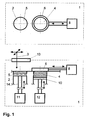
- eine Vorrichtung zur Herstellung von Miniaturkörpern oder mikrostrukturierten Körpern auf einem Träger in einer Bearbeitungskammer mit Laserstrahlen mit einer Ringrakel und einem Vorratsraum in einer Drauf und einer Seitenansicht,
- Fig. 2
- eine Vorrichtung mit zwei Ringrakeln und zwei Vorratsräumen in einer Drauf- und einer Seitenansicht,
- Fig. 3
- eine Vorrichtung mit dem Bauraum im Mittelpunkt und mehreren schwenkbaren Ringrakeln und
- Fig. 4
- eine Vorrichtung mit einer Ringrakel, einem Vorratsraum für eine Paste oder ein Gel mit den Partikeln und einem Abstreifer zur Reinigung der Ringrakel.
- Fig. 1
- a device for producing miniature bodies or microstructured bodies on a carrier in a processing chamber with laser beams with a ring doctor and a storage space in a top view and a side view,
- Fig. 2
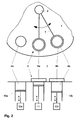
- a device with two ring doctor blades and two pantries in a top view and a side view,
- Fig. 3
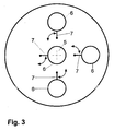
- a device with the installation space in the center and several pivotable ring doctor blades and
- Fig. 4
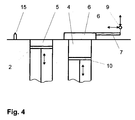
- a device with a ring doctor, a storage space for a paste or a gel with the particles and a scraper for cleaning the ring doctor.
Verfahren und Vorrichtungen zur Herstellung von Miniaturkörpern oder mikrostrukturierten Körpern auf einem Träger 2 in einer Bearbeitungskammer 1 mit Laserstrahlen 3 mindestens eines Lasers im Vakuum oder unter Schutzgas werden nachfolgend in den Ausführungsbeispielen zusammen näher erläutert.Methods and apparatus for the production of miniature bodies or microstructured bodies on a
Mit der Anwendung des Verfahrens werden Miniaturkörper aus Wolfram mit einer Auflösung < 50 µm hergestellt. Dazu befindet sich in der Bearbeitungskammer 1 ein Träger 2 in einem Bauraum 5 für die Miniaturkörper, ein Vorratsraum 4 für Partikel als Pulver bestehend aus Wolfram-Nanopulver und eine Transportvorrichtung für Partikel von dem Vorratsraum 4 zu dem Bauraum 5 und Träger 2. Die Partikel des Wolfram-Nanopulvers haben vorzugsweise eine Größe von 300 nm. Die Transportvorrichtung ist eine Ringrakel 6 mit einer in sich geschlossenen Klinge. Eine kreisförmig ausgebildete Ringrakel 6 befindet sich an mindestens einem Konstruktionselement, welches weiterhin mit wenigstens einem Antrieb 8 gekoppelt ist. Ein Konstruktionselement ist im einfachsten Fall ein stangenförmiger Körper 7, der mit der Ringrakel 6 an einem translatorischen oder rotatorischen Antrieb 8 befestigt ist. Im letzteren Fall vollführt die Ringrakel 6 eine kreisförmige Bewegung, wobei in der Bewegungsbahn wenigstens ein Bauraum 5 mit einem Träger 2 und mindestens ein Vorratsraum 4 angeordnet sind. Die
- an einer in seiner Länge veränderbaren und einstellbaren Einrichtung, zum Beispiel zwei ineinander geführten teleskopartigen Körpern, befestigt und mit einem rotatorischen Antrieb gekoppelt,
- an einer in seiner Länge veränderbaren und einstellbaren Einrichtung befestigt, wobei diese mit einem translatorischen Antrieb so gekoppelt ist, dass die Ringrakel in einer x- und y-Ebene bewegbar ist, oder
- an einem ebenen Drehgelenkgetriebe befestigt sein.
- attached to a length adjustable and adjustable device, for example two telescoping bodies, and coupled to a rotary drive,
- attached to a changeable in its length and adjustable device, which is coupled to a translational drive so that the annular blade is movable in an x and y plane, or
- be attached to a flat pivot gear.
In einer weiteren Ausführungsform werden Miniaturkörper aus Kupfer und Wolfram/Kupfer mit der Verwendung entweder eines Pulvers aus Kupfer-Mikropartikeln oder eines Gemisches aus Kupfermikro- und Wolfram-Nanopartikeln erzeugt. Die Absenkung des Trägers 2 erfolgt in Schritten von ca. 2 µm.In another embodiment, miniature bodies of copper and tungsten / copper are produced using either a powder of copper microparticles or a mixture of copper micro- and tungsten nanoparticles. The lowering of the
Miniaturkörper aus Silber und Wolfram/Silber mit der Verwendung entweder eines Pulvers aus Silber-Mikropatikeln oder eines Gemisches aus Silbermikro- und Wolfram-Nanopartikeln können in einer weiteren Ausführungsform erzeugt werden. Die Absenkung des Trägers 2 erfolgt in Schritten von ca. 2 µm.Silver and tungsten / silver miniature bodies with the use of either a silver microparticle powder or a mixture of silver micro- and tungsten nanoparticles may be produced in another embodiment. The lowering of the
Miniaturkörper aus Titan können in einer weiteren Ausführungsform mit der Verwendung eines Pulvers aus Titan-Mikro- und/oder Nanopartikeln erzeugt werden. Die Absenkung des Trägers 2 erfolgt in Schritten von ca. 2 µm.Titanium miniature bodies can be produced in a further embodiment with the use of a powder of titanium micro- and / or nanoparticles. The lowering of the
Miniaturkörper aus Aluminium können in einer weiteren Ausführungsform unter Verwendung von Pulver aus Aluminium-Mikropartikeln hergestellt werden. Der Sintervorgang erfolgt mit kleinerer Laserleistung von 0,8 W und zur Generierung der separierbaren Abstandskörper wird eine Leistung von 0,25 W verwendet.Aluminum miniature bodies may be made in another embodiment using aluminum microparticle powder. The sintering process is carried out with a smaller laser power of 0.8 W and to generate the separable spacer body, a power of 0.25 W is used.
In einer weiteren Ausführungsform können Miniaturkörper aus Aluminium/Titan mit der Verwendung eines Gemisches aus Aluminium- und Titan-Mikro- und/oder Nanopartikeln erzeugt werden. Der Sintervorgang erfolgt mit einer Laserleistung von 0,8 W und zur Generierung der separierbaren Abstandskörper wird eine Leistung von 0,25 W verwendet.In another embodiment, aluminum / titanium miniature bodies may be produced using a mixture of aluminum and titanium micro- and / or nanoparticles. The sintering process is performed with a laser power of 0.8 W and to generate the separable spacer body, a power of 0.25 W is used.
In einer weiteren Ausführungsform besteht die Schicht aus einer Paste mit den Wolfram-Nanopartikeln und wird im Vakuum mit einem Druck unmittelbar über dem Dampfdruck des Binders vorgetrocknet und durch Erwärmung mittels Laserstrahlen 3 entbindert. Die Ringrakel 6 wird vor der Rückbewegung angehoben und anschließend über eine Reinigungseinrichtung in Form einer Gummilippe 15 bewegt und somit gereinigt (Darstellung in der
Ein Verfahren und eine Vorrichtung zur Herstellung von mikrostrukturierten Körpern in Form von Zahninlays mit Laserstrahlen 3 mindestens eines Lasers im Vakuum oder unter Schutzgas auf einem Träger 2 in einer Bearbeitungskammer 1 werden nachfolgend näher erläutert.A method and an apparatus for producing microstructured bodies in the form of dental inlays with laser beams 3 of at least one laser in vacuum or under protective gas on a
Die Vorrichtung entspricht im Wesentlichen denen des ersten Ausführungsbeispiels. Das Verfahren wird jedoch nur unter Schutzgas durchgeführt. Die Schicht wird aus Paste oder Gel erzeugt. Die Vortrocknung und Entbinderung der Schicht geschieht durch schnelles Scannen des Laserstrahls 3 über die gesamte Schicht. Die Schichtdicke ist ≥ 5 µm und ≤ 20 µm. Der Laser arbeitet im Multimode-Betrieb, wodurch ein größerer Strahlfleckdurchmesser erzeugt wird. Die Laserleistung beträgt vorzugsweise 3 W zum Sintern der mikrostrukturierten Körper und vorzugsweise 1 W zum Sintern der separierbaren Abstandskörper. Die Rakel ist vorzugsweise eine Ringrakel 6. Nach dem Auftragvorgang wird die Ringrakel 6 über das Antriebssystem 9 angehoben und auf eine Gummilippe 15 als Reinigung geführt. Nach dem Reinigungsvorgang wird die Ringrakel 6 wieder über dem Vorratsraum 4a platziert und kann neu befüllt werden. Zusätzlich befindet sich in der Vorrichtung mindestens ein weiterer Vorratsraum 4b für Paste oder Gel. In den mindestens zwei Vorratsräumen 4a, 4b befinden sich hinsichtlich einer Färbung nach dem Sintern unterschiedliche Pasten oder Gele, vorzugsweise weiß und graugelb. Bei der Herstellung können durch Anwendung eines Dithering-Verfahrens in Form von sich entsprechend wechselnden Schichten aus den unterschiedlichen Pasten oder Gelen alle Farben zwischen weiß und graugelb erzeugt werden. Dadurch ist eine optimale farbliche Anpassung des Inlays an den Zahn möglich. Alternativ dazu werden zwei kreisförmig bewegbare Ringrakel 6, die gleichzeitig als Vorratsraum dienen, eingesetzt. Die Beschickung der Ringrakel 6 erfolgt durch das aufklappbar ausgestaltete Einkoppelfenster 13 für die Laserstrahlen 3 von oben. Der Vorteil dieser Variante besteht darin, dass die Ringrakel 6 nur in eine Richtung bewegt werden muss und damit kein Überfahren der neu aufgebrachten Schicht erfolgt. Ein Anheben der Ringrakel ist nicht notwendig. Zur Reinigung werden die Ringrakel 6 an einem Abstreifer vorbeigeführt.The device substantially corresponds to that of the first embodiment. However, the process is carried out only under protective gas. The layer is made of paste or gel. The predrying and debinding of the layer is done by fast scanning of the laser beam 3 over the entire layer. The layer thickness is ≥ 5 μm and ≤ 20 μm. The laser operates in multimode mode, producing a larger beam spot diameter. The laser power is preferably 3 W for sintering the microstructured body and preferably 1 W for sintering the separable spacer body. The doctor blade is preferably an
In weiteren Ausführungsformen der Ausführungsbeispiele kann ein Miniaturkörper oder ein mikrostrukturierter Körper mit einem vorgefertigten Körper als Bestandteil realisiert werden. Der vorgefertigte Körper ist dabei auf dem Träger 2 angeordnet. Beim ersten Rakeln wird der Raum um den vorgefertigten Körper und über dem Träger 2 vollständig mit Pulver aufgefüllt. Dies schafft eine ausreichende Fixierung des vorgefertigten Körpers auf dem Träger 2. Anschließend werden Schichten mit oder aus Partikeln aufgetragen und nach jedem Auftrag die jeweilige Schicht mit Laserstrahlen 3 sowohl entsprechend den Konturen des Miniaturkörpers oder mikrostrukturierten Körpers in dieser Ebene so bestrahlt, dass Partikel als Wandung und Innenbereich des zu fertigenden Miniaturkörpers oder mikrostrukturierten Körpers in dieser Ebene durchgehend durch Sintern miteinander in der ersten Schicht zusätzlich mit dem vorgefertigten Körper verbunden werden und damit ein Miniaturkörper oder mikrostrukturierter Körper entsteht und dass auch partiell flächig, flächig oder linienförmig in dieser Ebene zu kleine Kontaktbereichsstrukturen und Leerstellen aufweisenden und damit separierbaren Abstandskörpern gesintert werden, wobei sowohl eine statische Festigkeit entsteht als auch eine geringe Beständigkeit gegen Scherkräfte besteht. Die Vereinzelung des Miniaturkörpers oder des mikrostrukturierten Körpers und der Abstandskörper erfolgt vorteilhafterweise mit dem Beaufschlagen von Ultraschall. Zwischen Träger 2 und dem Miniaturkörper oder mikrostrukturierten Körper besteht keine feste Bindung, so dass eine Trennung leicht möglich ist.In further embodiments of the embodiments, a miniature body or a microstructured body can be realized with a prefabricated body as a component. The prefabricated body is arranged on the
Claims (10)
- Method for producing miniature bodies or microstructured bodies on a support in a processing chamber by laser beams of at least one laser in a vacuum or protective gas atmosphere, characterized in that layers comprising or consisting of particles are applied and, after each application, the respective layer is irradiated with laser beams (3) in such a way that particles are sintered in a partially planar, planar or linear manner on the corresponding plane to form spacer bodies that have small contact area structures and voids and can thus be separated, thereby producing both static stability and a low resistance to shearing forces, in that layers comprising or consisting of particles are applied and, after each application, the respective layer is irradiated at least in accordance with the contours of the miniature bodies or microstructured bodies in this plane in such a way that particles are bonded together by sintering throughout as the wall and inner region of the miniature bodies or microstructured bodies in this plane and in this way the miniature bodies or microstructured bodies are produced, and in that the support (2) with the miniature bodies or microstructured bodies and the separable spacer bodies is subjected to ultrasound to separate the miniature bodies or microstructured bodies from the support (2) and from the separable spacer bodies.
- Method according to Patent Claim 1, characterized in that layers comprising or consisting of particles are applied and, after each application, the respective layer is irradiated with laser beams (3) in such a way that particles are sintered in a partially planar, planar or linear manner on the corresponding plane to form spacer bodies that have small contact area structures and voids and can thus be separated, thereby producing both static stability and a low resistance to shearing forces, in that layers comprising or consisting of particles are applied and, after each application, the respective layer is both irradiated with laser beams (3) in accordance with the contours of the miniature bodies or microstructured bodies in this plane in such a way that particles are bonded together by sintering throughout as the wall and inner region of the miniature bodies or microstructured bodies in this plane and in this way the miniature bodies or microstructured bodies are produced, and sintered in a partially planar, planar or linear manner in this plane to form spacer bodies that have small contact area structures and voids and can thus be separated, thereby producing both static stability and a low resistance to shearing forces, and in that the support (2) with the miniature bodies or microstructured bodies and the separable spacer bodies is subjected to ultrasound to separate the miniature bodies or microstructured bodies from the support (2) and from the separable spacer bodies.
- Method according to Patent Claim 1, characterized in that layers comprising or consisting of particles are applied to at least one prefabricated body arranged on the support (2) and surrounded by layers comprising or consisting of particles and, after each application, the respective layer is irradiated with laser beams (3) in accordance with the contour or contours of the miniature bodies or microstructured bodies in this plane in such a way that particles are bonded together by sintering throughout as the wall and inner region of the miniature bodies or microstructured bodies in this plane, in the first layer additionally bonded with the prefabricated body, and in this way the miniature bodies or microstructured bodies are produced, and sintered in a partially planar, planar or linear manner in this plane to form spacer bodies that have small contact area structures and voids and can thus be separated, thereby producing both static stability and a low resistance to shearing forces, and in that the support (2) with the miniature bodies or microstructured bodies and the separable spacer bodies is subjected to ultrasound to separate the miniature bodies or microstructured bodies from the separable spacer bodies.
- Method according to one of Patent Claims 1, 2 and 3, characterized in that the pulse frequency and the speed with which the laser beams (3) are made to pass over the layer to generate the miniature bodies or microstructured bodies and the spacer bodies are the same and in that the laser power is less during the production of the spacer bodies than during the production of the miniature bodies or microstructured bodies or in that the laser power for generating the miniature bodies or microstructured bodies and the spacer bodies is the same and in that the pulse frequency and the speed with which the laser beams (3) are made to pass over the layer are greater during the production of the spacer bodies than during the production of the miniature bodies or microstructured bodies.
- Method according to one of Patent Claims 1, 2, 3 and 4, characterized in that the layers comprising or consisting of the particles are applied by a printing technique, by spraying or by at least one doctor blade.
- Method according to one of Patent Claims 1, 2, 3, 4 and 5, characterized in that the layers consisting of a paste comprising the particles are exposed in a vacuum to a pressure directly above the vapour pressure of the binder and are debinded by heating by means of laser beams (3).
- Method according to Patent Claim 5, characterized in that, before being irradiated with laser beams (3), the respective applied layer is compacted by means of exposing the support and/or the doctor blades to audible sound or ultrasound and/or by horizontally turning the doctor blades.
- Method according to Patent Claim 5, characterized in that the doctor blades are made to pass in a direction over the support (2) in a closed path of movement.
- Method according to one of the preceding patent claims, characterized in that at least two different materials with the same or different colours are used for different layers.
- Method according to Patent Claim 9, characterized in that a layer-by-layer dithering method is used.
Applications Claiming Priority (3)
| Application Number | Priority Date | Filing Date | Title |
|---|---|---|---|
| DE10309519 | 2003-02-26 | ||
| DE10309519A DE10309519B4 (en) | 2003-02-26 | 2003-02-26 | Method and device for producing miniature bodies or microstructured bodies |
| PCT/EP2004/001892 WO2004076101A2 (en) | 2003-02-26 | 2004-02-26 | Method and device for producing miniature bodies or microstructured bodies |
Publications (2)
| Publication Number | Publication Date |
|---|---|
| EP1597003A2 EP1597003A2 (en) | 2005-11-23 |
| EP1597003B1 true EP1597003B1 (en) | 2010-04-07 |
Family
ID=32864130
Family Applications (1)
| Application Number | Title | Priority Date | Filing Date |
|---|---|---|---|
| EP04714738A Expired - Lifetime EP1597003B1 (en) | 2003-02-26 | 2004-02-26 | Method for producing miniature bodies or microstructured bodies |
Country Status (10)
| Country | Link |
|---|---|
| US (1) | US20070145629A1 (en) |
| EP (1) | EP1597003B1 (en) |
| JP (1) | JP2006519925A (en) |
| KR (1) | KR101107361B1 (en) |
| CN (1) | CN100406168C (en) |
| AT (1) | ATE463315T1 (en) |
| CA (1) | CA2517374A1 (en) |
| DE (2) | DE10309519B4 (en) |
| NO (1) | NO20053931D0 (en) |
| WO (1) | WO2004076101A2 (en) |
Cited By (1)
| Publication number | Priority date | Publication date | Assignee | Title |
|---|---|---|---|---|
| DE102009053190A1 (en) * | 2009-11-08 | 2011-07-28 | FIT Fruth Innovative Technologien GmbH, 92331 | Apparatus and method for producing a three-dimensional body |
Families Citing this family (41)
| Publication number | Priority date | Publication date | Assignee | Title |
|---|---|---|---|---|
| DE102007018126A1 (en) * | 2007-04-16 | 2008-10-30 | Eads Deutschland Gmbh | Production method for high-temperature components and component produced therewith |
| DE102007057130B3 (en) * | 2007-11-24 | 2009-01-22 | Hochschule Mittweida (Fh) | Doctor blade system for building up layers of powder for sintering and bonding to each other comprises doctor ring which moves along pair of straight guide rails, rails rotating laterally as ring moves along |
| DE102008022495A1 (en) * | 2008-05-07 | 2009-11-12 | Fockele, Matthias, Dr. | Device for producing object by layerwise construction from powdered metallic or ceramic material, comprises housing with process chamber, support for layer construction, irradiation device, powder layer preparation device, and gear unit |
| GB0816308D0 (en) | 2008-09-05 | 2008-10-15 | Mtt Technologies Ltd | Optical module |
| CH700273A1 (en) * | 2009-01-26 | 2010-07-30 | Hanspeter Ott | Producing three-dimensional jewelry pieces made of metal, comprises repeatedly applying a metal powder on a substrate and/or highly-adjustable platform in a layer-wise manner, and partially melting the powder layer at a predetermined point |
| DE202009018948U1 (en) * | 2009-12-02 | 2014-10-10 | Exone Gmbh | Plant for the layered construction of a molding with a coater cleaning device |
| DE102010004849A1 (en) * | 2010-01-16 | 2011-07-21 | Technische Universität München, 80333 | Powder application device and manufacturing facility |
| EP2359964B1 (en) * | 2010-01-26 | 2013-11-20 | Alstom Technology Ltd | Process for Producing a 3-Dimensional Component by Means of Selective Laser Melting (SLM) |
| DE102010024226A1 (en) * | 2010-06-18 | 2011-12-22 | Mtu Aero Engines Gmbh | Producing or repairing component, preferably components of turbomachine, comprises applying first material layer on base and solidifying, producing first component portion, and applying second material layer on produced component portion |
| BE1020619A3 (en) * | 2011-02-04 | 2014-02-04 | Layerwise N V | METHOD FOR LAYERALLY MANUFACTURING THIN-WANDED STRUCTURES. |
| DE102011014610B3 (en) * | 2011-03-19 | 2012-05-03 | Hochschule Mittweida (Fh) | Device for applying powder for additive fabrication process, comprises a platform lowered with a drive for a component, and a wall region of the powder reservoir movable with the device, where an area of the bottom is movable |
| DE102011007067A1 (en) * | 2011-04-08 | 2012-10-11 | Siemens Aktiengesellschaft | Method for selective laser melting and installation for carrying out this method |
| DE102011086889A1 (en) | 2011-11-22 | 2013-05-23 | Mtu Aero Engines Gmbh | Generative production of a component |
| FR2998497B1 (en) * | 2012-11-29 | 2021-01-29 | Association Pour La Rech Et Le Developpement De Methodes Et Processus Industriels Armines | PROCESS FOR SELECTIVE MERGING OF BEDS OF POWDER BY HIGH ENERGY BEAM UNDER A GAS DEPRESSION |
| DE102013005165B4 (en) | 2013-03-23 | 2020-07-16 | Hochschule Mittweida (Fh) | Process and device for the production of micro-structured grid plates with a high aspect ratio |
| DE102014212176A1 (en) * | 2014-06-25 | 2015-12-31 | Siemens Aktiengesellschaft | Powder bed-based additive manufacturing process and apparatus for carrying out this process |
| GB201420601D0 (en) * | 2014-11-19 | 2015-01-07 | Digital Metal Ab | Method and apparatus for manufacturing a series of objects |
| GB201509284D0 (en) * | 2015-05-29 | 2015-07-15 | M & I Materials Ltd | Selective laser melting |
| NL2015381B1 (en) * | 2015-09-01 | 2017-03-20 | Stichting Energieonderzoek Centrum Nederland | Additive manufacturing method and apparatus. |
| WO2017085470A1 (en) | 2015-11-16 | 2017-05-26 | Renishaw Plc | Module for additive manufacturing apparatus and method |
| CN105750546B (en) * | 2016-04-29 | 2017-07-14 | 西安交通大学 | A kind of selective laser fusing two-dimensional ultrasound adds vibrating device |
| CN106079439B (en) * | 2016-06-14 | 2018-03-16 | 西安交通大学 | A kind of Meta Materials photocuring printing device that clamping is touched using ultrasonic wave added |
| DE102016214249A1 (en) * | 2016-08-02 | 2018-02-08 | Technische Universität Dresden | Device for the generative production of a three-dimensional body in a powder bed |
| GB2554738A (en) | 2016-10-07 | 2018-04-11 | Res Center Pharmaceutical Engineering Gmbh | A system and a method for constant micro dosing and feeding of powder material |
| DE102016120044A1 (en) * | 2016-10-20 | 2018-04-26 | Cl Schutzrechtsverwaltungs Gmbh | Device for the additive production of three-dimensional objects |
| US20180200791A1 (en) * | 2017-01-13 | 2018-07-19 | General Electric Company | Dynamically damped recoater |
| CN107199339B (en) * | 2017-07-24 | 2023-04-21 | 扬州扬芯激光技术有限公司 | Powder spreading accurate control device and method for laser rapid prototyping equipment |
| WO2019079443A1 (en) * | 2017-10-20 | 2019-04-25 | Formlabs, Inc. | Integrated preheating and coating of powder material in additive fabrication |
| WO2019094286A1 (en) * | 2017-11-08 | 2019-05-16 | General Electric Company | Omnidirectional recoater |
| CN107914014B (en) * | 2017-11-24 | 2019-07-12 | 西北有色金属研究院 | A kind of electron beam selective melting manufacturing process of pure tungsten metal part |
| JP6676688B2 (en) * | 2018-04-06 | 2020-04-08 | 株式会社ソディック | Manufacturing method of three-dimensional objects |
| KR101891227B1 (en) * | 2018-04-09 | 2018-08-27 | 한국생산기술연구원 | 3d laser printer for flattening device and method for producing 3d objects using the same |
| JP7321624B2 (en) * | 2018-12-25 | 2023-08-07 | エルジー・ケム・リミテッド | Molding apparatus and molded product manufacturing method |
| JP7365168B2 (en) | 2019-09-04 | 2023-10-19 | 株式会社荏原製作所 | AM device |
| EP3865229A1 (en) * | 2020-02-11 | 2021-08-18 | Heraeus Additive Manufacturing GmbH | Production system for layerwise application of a powder material on a build platform |
| EP3967429A1 (en) * | 2020-09-11 | 2022-03-16 | Siemens Aktiengesellschaft | Separation device, additive manufacturing machine with separation device, separation method and additive manufacturing method with the separation method |
| DE102020123753A1 (en) * | 2020-09-11 | 2022-03-17 | Deutsches Zentrum für Luft- und Raumfahrt e.V. | Apparatus and method for additive manufacturing of components in environments with different gravitation and with material of different fluidity |
| CN113172235B (en) * | 2021-04-02 | 2022-10-28 | 西安交通大学 | Electrical contact preparation method based on multi-material metal synchronous 3D printing technology |
| CN114505498A (en) * | 2022-04-19 | 2022-05-17 | 济南森峰激光科技股份有限公司 | Laser rapid prototyping method and device easy for entity separation |
| CN114515840A (en) * | 2022-04-21 | 2022-05-20 | 济南森峰激光科技股份有限公司 | Laser rapid forming device based on magnetic forming space and powder paving method |
| DE102022002558A1 (en) | 2022-07-05 | 2024-01-11 | Hochschule Mittweida (FH), Körperschaft des öffentlichen Rechts | Use of at least one doctor blade for stripping off powder applied as a layer from a powder bed for subsequent exposure to laser beams from at least one laser |
Family Cites Families (15)
| Publication number | Priority date | Publication date | Assignee | Title |
|---|---|---|---|---|
| US5637175A (en) * | 1988-10-05 | 1997-06-10 | Helisys Corporation | Apparatus for forming an integral object from laminations |
| US5204055A (en) * | 1989-12-08 | 1993-04-20 | Massachusetts Institute Of Technology | Three-dimensional printing techniques |
| CN1062486A (en) * | 1990-12-20 | 1992-07-08 | 吉林工业大学 | Technology for sintering powder metallurgical product by laser radiation |
| US5474719A (en) * | 1991-02-14 | 1995-12-12 | E. I. Du Pont De Nemours And Company | Method for forming solid objects utilizing viscosity reducible compositions |
| FR2678532A1 (en) * | 1991-07-02 | 1993-01-08 | Medart Claude | Manufacture of objects by means of stereolithography from powders or granules |
| JPH0596631A (en) * | 1991-10-08 | 1993-04-20 | Daikin Ind Ltd | Method and apparatus for optical shaping |
| US5252264A (en) * | 1991-11-08 | 1993-10-12 | Dtm Corporation | Apparatus and method for producing parts with multi-directional powder delivery |
| US5393482A (en) * | 1993-10-20 | 1995-02-28 | United Technologies Corporation | Method for performing multiple beam laser sintering employing focussed and defocussed laser beams |
| DE4436695C1 (en) * | 1994-10-13 | 1995-12-21 | Eos Electro Optical Syst | Stereolithography, the making of a three dimensional object by irradiation of powder or liquid layers |
| DE69528253T2 (en) * | 1995-06-21 | 2003-08-07 | Minnesota Mining & Mfg | Breakable core and cover with an expanded elastomeric tube and a breakable core |
| DE69604043T2 (en) * | 1995-11-09 | 2000-04-13 | Toyota Motor Co Ltd | Process for producing a mold from layers and a casting made therewith |
| TWI228114B (en) * | 1999-12-24 | 2005-02-21 | Nat Science Council | Method and equipment for making ceramic work piece |
| JP3943315B2 (en) * | 2000-07-24 | 2007-07-11 | 松下電工株式会社 | Manufacturing method of three-dimensional shaped object |
| AU2002222885A1 (en) * | 2000-11-27 | 2002-06-03 | Kinergy Pte Ltd | Method and apparatus for creating a three-dimensional metal part using high-temperature direct laser melting |
| US6786711B2 (en) * | 2001-06-08 | 2004-09-07 | The United States Of America As Represented By The Secretary Of The Navy | Method and system for production of fibrous composite prototypes using acoustic manipulation in stereolithography |
-
2003
- 2003-02-26 DE DE10309519A patent/DE10309519B4/en not_active Expired - Fee Related
-
2004
- 2004-02-26 CA CA2517374A patent/CA2517374A1/en not_active Abandoned
- 2004-02-26 US US10/546,954 patent/US20070145629A1/en not_active Abandoned
- 2004-02-26 WO PCT/EP2004/001892 patent/WO2004076101A2/en active Application Filing
- 2004-02-26 EP EP04714738A patent/EP1597003B1/en not_active Expired - Lifetime
- 2004-02-26 DE DE502004010996T patent/DE502004010996D1/en not_active Expired - Lifetime
- 2004-02-26 KR KR1020057015820A patent/KR101107361B1/en not_active IP Right Cessation
- 2004-02-26 AT AT04714738T patent/ATE463315T1/en active
- 2004-02-26 JP JP2006501955A patent/JP2006519925A/en active Pending
- 2004-02-26 CN CNB2004800051915A patent/CN100406168C/en not_active Expired - Fee Related
-
2005
- 2005-08-23 NO NO20053931A patent/NO20053931D0/en not_active Application Discontinuation
Cited By (2)
| Publication number | Priority date | Publication date | Assignee | Title |
|---|---|---|---|---|
| DE102009053190A1 (en) * | 2009-11-08 | 2011-07-28 | FIT Fruth Innovative Technologien GmbH, 92331 | Apparatus and method for producing a three-dimensional body |
| US8956692B2 (en) | 2009-11-08 | 2015-02-17 | Fit Ag | Device and method for manufacturing a three-dimensional body |
Also Published As
| Publication number | Publication date |
|---|---|
| WO2004076101A3 (en) | 2005-02-17 |
| CA2517374A1 (en) | 2004-09-10 |
| DE10309519B4 (en) | 2006-04-27 |
| NO20053931L (en) | 2005-08-23 |
| CN100406168C (en) | 2008-07-30 |
| KR20050103505A (en) | 2005-10-31 |
| US20070145629A1 (en) | 2007-06-28 |
| DE10309519A1 (en) | 2004-09-16 |
| ATE463315T1 (en) | 2010-04-15 |
| KR101107361B1 (en) | 2012-01-19 |
| EP1597003A2 (en) | 2005-11-23 |
| DE502004010996D1 (en) | 2010-05-20 |
| NO20053931D0 (en) | 2005-08-23 |
| CN1753748A (en) | 2006-03-29 |
| WO2004076101A2 (en) | 2004-09-10 |
| JP2006519925A (en) | 2006-08-31 |
Similar Documents
| Publication | Publication Date | Title |
|---|---|---|
| EP1597003B1 (en) | Method for producing miniature bodies or microstructured bodies | |
| DE69911178T2 (en) | METHOD FOR THE QUICK PRODUCTION OF A PROTOTYPE BY LASER SINTERING AND DEVICE THEREFOR | |
| EP2361751B1 (en) | Method and device for producing a three dimensional object, particularly suitable for use in microtechnology | |
| EP2291260B1 (en) | Process chamber for selective laser sintering and use thereof for making a piece | |
| DE3917277C2 (en) | Method and device for producing finished parts as a composite body made of powdery materials | |
| DE10344902B4 (en) | Method for producing a three-dimensional object | |
| DE102012109262A1 (en) | Method for stabilizing a powder bed by means of negative pressure for additive manufacturing | |
| DE102005025199A1 (en) | Apparatus for rapidly producing shaped articles, e.g. of ceramic, by laser-induced sintering and/or fusion of particles, includes particle transporting annular doctor blade with particle compressing roller | |
| EP3275654A1 (en) | Coating unit, coating method, method and device for generating a three-dimensional object | |
| EP3723249A1 (en) | Method for producing a magnetic sheet and a magnetic sheet stack and electric machine and electric vehicle | |
| EP3331687A1 (en) | Method and device for producing a three-dimensional object | |
| DE102016208196A1 (en) | Method and device for the generative production of three-dimensional composite components | |
| EP2577762B1 (en) | Method for producing a piezo actuator and piezo actuator | |
| DE102004022386B4 (en) | Molding apparatus for micro-components has molding chamber in which particles are sintered by laser, external acousto-optical modulator below laser controlling beam so that it operates in pulsed or continuous wave mode | |
| DE102004022385B4 (en) | Device for the rapid production of microbodies | |
| DE4439124A1 (en) | Method and device for producing a three-dimensional object | |
| EP1819455A2 (en) | Method for the production of an ultrasonic transducer | |
| DE102018008736A1 (en) | METHOD AND DEVICE FOR PRODUCING A THREE-DIMENSIONAL OBJECT ON A BUILDING PLATFORM | |
| DE102009005859B3 (en) | Homogenizing powder charge, e.g. of ceramic or steel, in powder compression molding production, by subjecting powder-filled mold to rotary vibration | |
| DE10332851A1 (en) | Calcium phosphate-resin-metal composite body and process for its production | |
| DE3906268A1 (en) | METHOD AND DEVICE FOR PRODUCING A PROFILE MULTIPLE FROM CERAMIC MATERIALS | |
| DE19945155A1 (en) | Method of making a drug | |
| DE19518994C1 (en) | Body of composite material, esp. implant | |
| WO2011117137A2 (en) | Method and device for producing a product by casting from liquid, pulpy, paste-like, powdery, granular, solid material and/or composition additives thereof | |
| DE10217670B4 (en) | Use of a ceramic suspension |
Legal Events
| Date | Code | Title | Description |
|---|---|---|---|
| PUAI | Public reference made under article 153(3) epc to a published international application that has entered the european phase |
Free format text: ORIGINAL CODE: 0009012 |
|
| 17P | Request for examination filed |
Effective date: 20050908 |
|
| AK | Designated contracting states |
Kind code of ref document: A2 Designated state(s): AT BE BG CH CY CZ DE DK EE ES FI FR GB GR HU IE IT LI LU MC NL PT RO SE SI SK TR |
|
| AX | Request for extension of the european patent |
Extension state: AL LT LV MK |
|
| RAP1 | Party data changed (applicant data changed or rights of an application transferred) |
Owner name: 3D-MICROMAC AG |
|
| DAX | Request for extension of the european patent (deleted) | ||
| 17Q | First examination report despatched |
Effective date: 20090420 |
|
| RAP1 | Party data changed (applicant data changed or rights of an application transferred) |
Owner name: 3D-MICROMAC AG |
|
| GRAP | Despatch of communication of intention to grant a patent |
Free format text: ORIGINAL CODE: EPIDOSNIGR1 |
|
| RTI1 | Title (correction) |
Free format text: METHOD FOR PRODUCING MINIATURE BODIES OR MICROSTRUCTURED BODIES |
|
| GRAS | Grant fee paid |
Free format text: ORIGINAL CODE: EPIDOSNIGR3 |
|
| GRAA | (expected) grant |
Free format text: ORIGINAL CODE: 0009210 |
|
| AK | Designated contracting states |
Kind code of ref document: B1 Designated state(s): AT BE BG CH CY CZ DE DK EE ES FI FR GB GR HU IE IT LI LU MC NL PT RO SE SI SK TR |
|
| REG | Reference to a national code |
Ref country code: GB Ref legal event code: FG4D Free format text: NOT ENGLISH |
|
| REG | Reference to a national code |
Ref country code: CH Ref legal event code: EP |
|
| REG | Reference to a national code |
Ref country code: IE Ref legal event code: FG4D Free format text: LANGUAGE OF EP DOCUMENT: GERMAN |
|
| REF | Corresponds to: |
Ref document number: 502004010996 Country of ref document: DE Date of ref document: 20100520 Kind code of ref document: P |
|
| REG | Reference to a national code |
Ref country code: NL Ref legal event code: VDEP Effective date: 20100407 |
|
| PG25 | Lapsed in a contracting state [announced via postgrant information from national office to epo] |
Ref country code: SI Free format text: LAPSE BECAUSE OF FAILURE TO SUBMIT A TRANSLATION OF THE DESCRIPTION OR TO PAY THE FEE WITHIN THE PRESCRIBED TIME-LIMIT Effective date: 20100407 |
|
| REG | Reference to a national code |
Ref country code: IE Ref legal event code: FD4D |
|
| PG25 | Lapsed in a contracting state [announced via postgrant information from national office to epo] |
Ref country code: ES Free format text: LAPSE BECAUSE OF FAILURE TO SUBMIT A TRANSLATION OF THE DESCRIPTION OR TO PAY THE FEE WITHIN THE PRESCRIBED TIME-LIMIT Effective date: 20100718 Ref country code: SE Free format text: LAPSE BECAUSE OF FAILURE TO SUBMIT A TRANSLATION OF THE DESCRIPTION OR TO PAY THE FEE WITHIN THE PRESCRIBED TIME-LIMIT Effective date: 20100407 Ref country code: NL Free format text: LAPSE BECAUSE OF FAILURE TO SUBMIT A TRANSLATION OF THE DESCRIPTION OR TO PAY THE FEE WITHIN THE PRESCRIBED TIME-LIMIT Effective date: 20100407 |
|
| PG25 | Lapsed in a contracting state [announced via postgrant information from national office to epo] |
Ref country code: FI Free format text: LAPSE BECAUSE OF FAILURE TO SUBMIT A TRANSLATION OF THE DESCRIPTION OR TO PAY THE FEE WITHIN THE PRESCRIBED TIME-LIMIT Effective date: 20100407 |
|
| PG25 | Lapsed in a contracting state [announced via postgrant information from national office to epo] |
Ref country code: GR Free format text: LAPSE BECAUSE OF FAILURE TO SUBMIT A TRANSLATION OF THE DESCRIPTION OR TO PAY THE FEE WITHIN THE PRESCRIBED TIME-LIMIT Effective date: 20100708 Ref country code: CY Free format text: LAPSE BECAUSE OF FAILURE TO SUBMIT A TRANSLATION OF THE DESCRIPTION OR TO PAY THE FEE WITHIN THE PRESCRIBED TIME-LIMIT Effective date: 20100421 |
|
| PG25 | Lapsed in a contracting state [announced via postgrant information from national office to epo] |
Ref country code: EE Free format text: LAPSE BECAUSE OF FAILURE TO SUBMIT A TRANSLATION OF THE DESCRIPTION OR TO PAY THE FEE WITHIN THE PRESCRIBED TIME-LIMIT Effective date: 20100407 Ref country code: IE Free format text: LAPSE BECAUSE OF FAILURE TO SUBMIT A TRANSLATION OF THE DESCRIPTION OR TO PAY THE FEE WITHIN THE PRESCRIBED TIME-LIMIT Effective date: 20100407 Ref country code: PT Free format text: LAPSE BECAUSE OF FAILURE TO SUBMIT A TRANSLATION OF THE DESCRIPTION OR TO PAY THE FEE WITHIN THE PRESCRIBED TIME-LIMIT Effective date: 20100809 Ref country code: DK Free format text: LAPSE BECAUSE OF FAILURE TO SUBMIT A TRANSLATION OF THE DESCRIPTION OR TO PAY THE FEE WITHIN THE PRESCRIBED TIME-LIMIT Effective date: 20100407 |
|
| PLBE | No opposition filed within time limit |
Free format text: ORIGINAL CODE: 0009261 |
|
| STAA | Information on the status of an ep patent application or granted ep patent |
Free format text: STATUS: NO OPPOSITION FILED WITHIN TIME LIMIT |
|
| PG25 | Lapsed in a contracting state [announced via postgrant information from national office to epo] |
Ref country code: CZ Free format text: LAPSE BECAUSE OF FAILURE TO SUBMIT A TRANSLATION OF THE DESCRIPTION OR TO PAY THE FEE WITHIN THE PRESCRIBED TIME-LIMIT Effective date: 20100407 Ref country code: RO Free format text: LAPSE BECAUSE OF FAILURE TO SUBMIT A TRANSLATION OF THE DESCRIPTION OR TO PAY THE FEE WITHIN THE PRESCRIBED TIME-LIMIT Effective date: 20100407 Ref country code: SK Free format text: LAPSE BECAUSE OF FAILURE TO SUBMIT A TRANSLATION OF THE DESCRIPTION OR TO PAY THE FEE WITHIN THE PRESCRIBED TIME-LIMIT Effective date: 20100407 |
|
| 26N | No opposition filed |
Effective date: 20110110 |
|
| PGFP | Annual fee paid to national office [announced via postgrant information from national office to epo] |
Ref country code: IT Payment date: 20110225 Year of fee payment: 8 |
|
| BERE | Be: lapsed |
Owner name: 3D-MICROMAC A.G. Effective date: 20110228 |
|
| PG25 | Lapsed in a contracting state [announced via postgrant information from national office to epo] |
Ref country code: MC Free format text: LAPSE BECAUSE OF NON-PAYMENT OF DUE FEES Effective date: 20110228 |
|
| REG | Reference to a national code |
Ref country code: CH Ref legal event code: PL |
|
| PG25 | Lapsed in a contracting state [announced via postgrant information from national office to epo] |
Ref country code: CH Free format text: LAPSE BECAUSE OF NON-PAYMENT OF DUE FEES Effective date: 20110228 Ref country code: LI Free format text: LAPSE BECAUSE OF NON-PAYMENT OF DUE FEES Effective date: 20110228 |
|
| PG25 | Lapsed in a contracting state [announced via postgrant information from national office to epo] |
Ref country code: BE Free format text: LAPSE BECAUSE OF NON-PAYMENT OF DUE FEES Effective date: 20110228 |
|
| PG25 | Lapsed in a contracting state [announced via postgrant information from national office to epo] |
Ref country code: IT Free format text: LAPSE BECAUSE OF NON-PAYMENT OF DUE FEES Effective date: 20120226 |
|
| REG | Reference to a national code |
Ref country code: AT Ref legal event code: MM01 Ref document number: 463315 Country of ref document: AT Kind code of ref document: T Effective date: 20110226 |
|
| PG25 | Lapsed in a contracting state [announced via postgrant information from national office to epo] |
Ref country code: AT Free format text: LAPSE BECAUSE OF NON-PAYMENT OF DUE FEES Effective date: 20110226 |
|
| REG | Reference to a national code |
Ref country code: DE Ref legal event code: R082 Ref document number: 502004010996 Country of ref document: DE Representative=s name: PATENTANWAELTE RUFF, WILHELM, BEIER, DAUSTER &, DE |
|
| PG25 | Lapsed in a contracting state [announced via postgrant information from national office to epo] |
Ref country code: LU Free format text: LAPSE BECAUSE OF NON-PAYMENT OF DUE FEES Effective date: 20110226 |
|
| PG25 | Lapsed in a contracting state [announced via postgrant information from national office to epo] |
Ref country code: BG Free format text: LAPSE BECAUSE OF FAILURE TO SUBMIT A TRANSLATION OF THE DESCRIPTION OR TO PAY THE FEE WITHIN THE PRESCRIBED TIME-LIMIT Effective date: 20100707 Ref country code: TR Free format text: LAPSE BECAUSE OF FAILURE TO SUBMIT A TRANSLATION OF THE DESCRIPTION OR TO PAY THE FEE WITHIN THE PRESCRIBED TIME-LIMIT Effective date: 20100407 |
|
| PG25 | Lapsed in a contracting state [announced via postgrant information from national office to epo] |
Ref country code: HU Free format text: LAPSE BECAUSE OF FAILURE TO SUBMIT A TRANSLATION OF THE DESCRIPTION OR TO PAY THE FEE WITHIN THE PRESCRIBED TIME-LIMIT Effective date: 20100407 |
|
| REG | Reference to a national code |
Ref country code: DE Ref legal event code: R082 Ref document number: 502004010996 Country of ref document: DE Representative=s name: PATENTANWAELTE RUFF, WILHELM, BEIER, DAUSTER &, DE Effective date: 20130205 Ref country code: DE Ref legal event code: R081 Ref document number: 502004010996 Country of ref document: DE Owner name: 3D MICROPRINT GMBH, DE Free format text: FORMER OWNER: 3D-MICROMAC AG, 09126 CHEMNITZ, DE Effective date: 20140811 |
|
| REG | Reference to a national code |
Ref country code: GB Ref legal event code: 732E Free format text: REGISTERED BETWEEN 20150305 AND 20150311 |
|
| REG | Reference to a national code |
Ref country code: FR Ref legal event code: TP Owner name: 3D-MICROPRINT GMBH, DE Effective date: 20150303 |
|
| REG | Reference to a national code |
Ref country code: FR Ref legal event code: PLFP Year of fee payment: 13 |
|
| REG | Reference to a national code |
Ref country code: FR Ref legal event code: CD Owner name: 3D-MICROPRINT GMBH, DE Effective date: 20160627 |
|
| REG | Reference to a national code |
Ref country code: FR Ref legal event code: PLFP Year of fee payment: 14 |
|
| PGFP | Annual fee paid to national office [announced via postgrant information from national office to epo] |
Ref country code: FR Payment date: 20170220 Year of fee payment: 14 Ref country code: DE Payment date: 20170223 Year of fee payment: 14 |
|
| PGFP | Annual fee paid to national office [announced via postgrant information from national office to epo] |
Ref country code: GB Payment date: 20170221 Year of fee payment: 14 |
|
| REG | Reference to a national code |
Ref country code: DE Ref legal event code: R119 Ref document number: 502004010996 Country of ref document: DE |
|
| GBPC | Gb: european patent ceased through non-payment of renewal fee |
Effective date: 20180226 |
|
| REG | Reference to a national code |
Ref country code: FR Ref legal event code: ST Effective date: 20181031 |
|
| PG25 | Lapsed in a contracting state [announced via postgrant information from national office to epo] |
Ref country code: DE Free format text: LAPSE BECAUSE OF NON-PAYMENT OF DUE FEES Effective date: 20180901 |
|
| PG25 | Lapsed in a contracting state [announced via postgrant information from national office to epo] |
Ref country code: GB Free format text: LAPSE BECAUSE OF NON-PAYMENT OF DUE FEES Effective date: 20180226 Ref country code: FR Free format text: LAPSE BECAUSE OF NON-PAYMENT OF DUE FEES Effective date: 20180228 |