EP1596935B1 - Verfahren, vorrichtung und system zur kommunikation mit medizinischen geräten - Google Patents
Verfahren, vorrichtung und system zur kommunikation mit medizinischen geräten Download PDFInfo
- Publication number
- EP1596935B1 EP1596935B1 EP04708636A EP04708636A EP1596935B1 EP 1596935 B1 EP1596935 B1 EP 1596935B1 EP 04708636 A EP04708636 A EP 04708636A EP 04708636 A EP04708636 A EP 04708636A EP 1596935 B1 EP1596935 B1 EP 1596935B1
- Authority
- EP
- European Patent Office
- Prior art keywords
- rate
- medical device
- data
- implantable medical
- communication
- Prior art date
- Legal status (The legal status is an assumption and is not a legal conclusion. Google has not performed a legal analysis and makes no representation as to the accuracy of the status listed.)
- Expired - Lifetime
Links
Images


Classifications
-
- A—HUMAN NECESSITIES
- A61—MEDICAL OR VETERINARY SCIENCE; HYGIENE
- A61N—ELECTROTHERAPY; MAGNETOTHERAPY; RADIATION THERAPY; ULTRASOUND THERAPY
- A61N1/00—Electrotherapy; Circuits therefor
- A61N1/18—Applying electric currents by contact electrodes
- A61N1/32—Applying electric currents by contact electrodes alternating or intermittent currents
- A61N1/36—Applying electric currents by contact electrodes alternating or intermittent currents for stimulation
- A61N1/372—Arrangements in connection with the implantation of stimulators
- A61N1/37211—Means for communicating with stimulators
- A61N1/37252—Details of algorithms or data aspects of communication system, e.g. handshaking, transmitting specific data or segmenting data
-
- Y—GENERAL TAGGING OF NEW TECHNOLOGICAL DEVELOPMENTS; GENERAL TAGGING OF CROSS-SECTIONAL TECHNOLOGIES SPANNING OVER SEVERAL SECTIONS OF THE IPC; TECHNICAL SUBJECTS COVERED BY FORMER USPC CROSS-REFERENCE ART COLLECTIONS [XRACs] AND DIGESTS
- Y10—TECHNICAL SUBJECTS COVERED BY FORMER USPC
- Y10S—TECHNICAL SUBJECTS COVERED BY FORMER USPC CROSS-REFERENCE ART COLLECTIONS [XRACs] AND DIGESTS
- Y10S128/00—Surgery
- Y10S128/903—Radio telemetry
Definitions
- the invention relates generally to medical devices and, more particularly, to techniques for communicating with medical devices.
- Implantable medical devices are commonly used to treat and monitor patients. Examples of an IMD include implantable cardiac pacemakers, implantable defibrillators, implantable pacemaker/cardioverter/defibrillators, implantable muscular stimulus devices, implantable brain stimulators, other implantable organ stimulation devices, implantable drug delivery devices, implantable monitors, and the like. These disparate medical devices often apply one or more medical treatments, and generate a wealth of physiological data relating to the condition of the patient.
- This physiological data is often collected by use of telemetry, which generally refers to communication of data, instructions, and the like between an IMD and an external device, such as a medical device programmer or an external monitor.
- a communication "session" is established to communicate the physiological data to the external device, and to communicate any controls or commands from the external device to the IMD.
- the external device may obtain diagnostic data, event marker data, activity data and other data collected or identified by the IMD.
- the physiological data may be used to program the IMD for delivery of new or modified therapies.
- telemetry between an IMD and the external device can be used to improve or enhance therapy.
- the external device To establish the communication session, the external device often examines a defined frequency spectrum to select one of a number of defined communication channels. During this process, the medical device programmer examines the channels individually in an attempt to select an open channel. If the external device detects activity on the channel, e.g., communication between another device and an IMD, the external device examines a different channel.
- the external device and the IMD communicate in a bi-directional fashion using downlink and uplink communication messages.
- the external device and the IMD alternate between downlink and uplink communication messages, respectively.
- the external device transmits downlink communication messages and receives uplink communication messages.
- the IMD receives downlink communication messages and transmits uplink communication messages.
- Each downlink and uplink message pair may form a single frame within the communication session.
- the data exchange between the devices may vary greatly depending on a number of factors, including the amount of physiological data and programming commands to be transferred.
- the external device and IMD may exchange uplink and downlink messages at a reduced rate when higher-rates are unnecessary, thereby reducing power consumption by the IMD.
- the IMD transmits fewer uplink messages. This reduced transmission allows the implant to save energy associated with the transmit operations.
- the external device transmits fewer downlink messages when there is less information to downlink to the IMD. This allows the IMD to save energy associated with the receive operation.
- a communication gap may occur when the IMD is collecting physiological data in real-time per the request of the external device.
- another external device may erroneously determine that the communication channel is unused, and may attempt to initiate a communication session. This usage may interfere with the previously established communication session, and may result in data loss, consumption of additional power by the IMD in attempting to respond to erroneous communications, and possibly premature termination of the original communication sessions.
- the invention is directed to techniques for maintaining a communication session between an external device, e.g., a medical device programmer or a monitor, and an implantable medical device (IMD) to reduce the potential for conflict with other programmers.
- an external device e.g., a medical device programmer or a monitor
- IMD implantable medical device
- Document US-B1- 6 400 990 discloses a patient activated telemetry control unit as described in the preambule of claim 1.
- channel occupancy techniques for multi-channel medical device communication are used in an advantageous way.
- the techniques are described in reference to a medical device programmer. Nevertheless, the techniques may be applicable to any form of multi-channel communication between an external device and an IMD.
- the medical device programmer and the IMD may vary the rate at which data is exchanged via the communication channel depending on the amount of information to uplink or downlink, thereby conserving IMD power associated with the receive and transmit operations.
- the programmer may transmit additional downlink idle messages in the form of idle packets to occupy the communication channel when the channel would otherwise be unused. Moreover, the programmer may dynamically adjust the transfer rate of the idle packets to offset the reduced data exchange rate between the programmer and the IMD. In other words, the programmer may automatically insert an increased amount of idle packets as the IMD and the programmer agree to transfer less data, i.e., consume less uplink and downlink messages. Similarly, the programmer may automatically insert fewer idle packets in response to increased uplink and downlink data transfer rates.
- the invention is directed to a method comprising communicating data from a medical device programmer to an implantable medical device using a communication channel, and transmitting idle messages from the medical device programmer via the communication channel during gaps within the data communication.
- the invention is directed to a method comprising transmitting downlink communications from a medical device programmer to an implantable medical device at a first rate, wherein the downlink communications include data and idle messages.
- the method further comprises receiving the downlink communications with the implantable medical device at a second rate slower than the first rate to receive the data packets and not the idle messages.
- the invention is directed to a device comprising a transmit module to transmit telemetry signals to an implantable medical device over a communication channel, and a control unit that communicates data to the implantable medical device via the transmit module, and communicates idle messages over the communication channel during gaps within the data communication to the implantable medical device.
- the invention is directed to system comprising a medical device programmer to transmit downlink communications including data and idle messages through a communication channel at a first rate, and an implantable medical device to receive the downlink communications at a second rate slower than the first rate to receive the data packets and not the idle messages.
- the invention is directed to a computer-readable medium containing instructions.
- the instructions cause a programmable processor to communicate data from a medical device programmer to an implantable medical device using a communication channel, and transmit idle messages from the medical device programmer via the communication channel during gaps within the data communication.
- the invention is directed to a programmer comprising means for transmitting telemetry signals to an implantable medical device over a communication channel, and means for communicates data to the implantable medical device via the telemetry signals, wherein the communication means communicates idle messages over the communication channel during gaps within the data communication.
- the programmer may be able to achieve increased channel occupancy. This increased channel occupancy may assist other medical device programmers in correctly assessing the usage of the communication channel.
- the IMD is configured to disregard, i.e., not receive, the downlink messages while the programmer transmits the idle packets, the IMD does not consume additional energy even though channel communication has been increased.
- FIG. 1 is a conceptual diagram illustrating a programmer in communication with an exemplary implantable medical device ("IMD”) implanted in a patient.
- IMD implantable medical device
- FIG. 2 is a timing diagram that illustrates channel occupancy techniques.
- FIG. 3 is an exemplary block diagram of a programmer and an IMD that achieve increased channel occupancy as described herein.
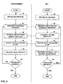
- FIG. 4 is a flowchart illustrating example operation of a programmer and an IMD implementing channel occupancy techniques.
- FIG. 1 is a conceptual diagram illustrating a programmer 5 in communication with an exemplary implantable medical device (“IMD") 8 implanted in a patient 10.
- IMD 8 is illustrated as an implantable cardiac pacemaker that delivers pacing pulses to a heart of patient 10.
- IMD 8 includes a hermetically-sealed enclosure 14 that may contain various elements.
- enclosure 14 may house an electrochemical cell, e.g., a lithium battery, circuitry that controls device operations such as delivery of stimulation pulses and records sensed events, physiological activity and patient conditions, and a control unit coupled to an antenna to communicate with programmer 5 via wireless telemetry signals 12.
- Programmer 5 uses telemetry signals 12 to initiate a communication "session" with IMD 8.
- programmer 5 may program IMD 8 to deliver particular therapies to patient 10, and may interrogate IMD 8 to obtain "session" data.
- the session data may include, for example, physiological data, e.g., diagnostic data, event marker data, activity data and other data currently stored by IMD 8. In this manner, telemetry allows bi-directional communication between IMD 8 and programmer 5.
- Programmer 5 and IMD 8 communicate via telemetry in accordance with one or more wireless communication techniques, such as standard RF telemetry protocols.
- Programmer 5 and IMD 8 may use, for example, electromagnetic signals, such as radio frequency (RF) signals and infrared (IR) frequency signals, sound waves, or even the patient's flesh as the transmission medium.
- RF radio frequency
- IR infrared
- conventional RF telemetry communication protocols for communicating with IMDs may be employed to effect communications between IMD 8 and programmer 5.
- IMD 8 may take the form of a variety of other implantable medical devices.
- an implantable medical device is a pacemaker-cardioverter-defibrillator ("PCD").
- PCD pacemaker-cardioverter-defibrillator
- Other examples include an implantable brain stimulator, an implantable gastric system stimulator, an implantable nerve stimulator or muscle stimulator, an implantable lower colon stimulator (e.g., in graciloplasty applications), an implantable drug or beneficial agent dispenser or pump, an implantable cardiac signal loop or other type of recorder or monitor, an implantable gene therapy delivery device, an implantable incontinence prevention or monitoring device, an implantable insulin pump or monitoring device, and so on.
- programmer 5 may receive a wide variety of session data including heart rate, heart rate variability, blood glucose levels, oxygen saturation, partial pressure of oxygen in the blood, blood pressure, baro-reflex measures, electrogram morphologies, lung wetness, and the like.
- IMD 8 may comprise a variety of patient monitoring devices, such as an external blood pressure monitor, an external heart rate monitor that measures heart rate and heart rate variability, an external blood glucose monitor, a user input device for generating an electronic questionnaire regarding patient systems or status, a Holter monitor, an external EKG or ECG monitor, an external cardiac signal loop recorder, a temporary cardiac pacing system having an external pulse generator, and the like.
- patient monitoring devices such as an external blood pressure monitor, an external heart rate monitor that measures heart rate and heart rate variability, an external blood glucose monitor, a user input device for generating an electronic questionnaire regarding patient systems or status, a Holter monitor, an external EKG or ECG monitor, an external cardiac signal loop recorder, a temporary cardiac pacing system having an external pulse generator, and the like.
- programmer 5 may communicate with external drug delivery systems that may provide physiological data in the form of recent dosage levels, dosing history, and the like.
- external drug delivery systems may provide physiological data in the form of recent dosage levels, dosing history, and the like.
- Another example is an external device for testing the blood to provide a variety of information, such as prothrombin time, which may assist in titrating anti-coagulation medication or the current levels of B-type natriuretic peptide (BNP), and aid the diagnosis and management of congestive heart failure (CHF).
- IMD 8 may correspond to a medical device used on non-human mammals or other animals.
- the techniques described herein may be readily used with a wide variety of medical devices including implanted and non-implanted medical devices used to deliver therapy or gather physiological information in humans, mammals, or other types of living beings.
- programmer 5 examines a frequency spectrum to select one of a number of defined communication channels. During this process, programmer 5 may examine the channels individually in an attempt to select an unoccupied channel. Upon detecting an unoccupied channel, programmer 5 attempts to initiate the communication session with IMD 8. Once established, programmer 5 and IMD 8 communicate in bi-directional fashion using downlink and uplink communication messages. W one embodiment, programmer 5 and IMD 8 communicate using a frame-based protocol in which each downlink and uplink message pair may form a single frame.
- programmer 5 and IMD 8 may vary the rate at which data is exchanged via the communication channel depending on the amount of information to uplink or downlink. For example, IMD 8 may transmit fewer uplink messages, i.e., skip uplink messages for certain frames, when there is less information to transmit. In this manner, IMD 8 may conserve power associated with the transmit operation. In similar fashion, IMD 8 listens for downlink messages from programmer 5 at the reduced rate, thereby conserving power associated with the receive operation.
- programmer 5 transmits downlink idle messages, which may be in the form of idle packets, to occupy the communication channel when the channel would otherwise be unused. Moreover, programmer 5 may dynamically adjust the transfer rate of the idle packets to offset the reduced data exchange rate between the programmer and IMD 8. In other words, programmer 5 may automatically insert more idle packets as IMD 8 and the programmer agree to transfer less data, i.e., consume less uplink and downlink messages. Similarly, programmer 5 may automatically insert fewer idle packets in response to increased uplink and downlink data transfer rates.
- programmer 5 can achieve increased channel occupancy, and may maintain at least a threshold occupancy rate for the channel.
- programmer 5 utilize idle packets to achieve at substantially meet or exceed a configurable threshold occupancy, e.g., 25%, 50% occupancy, 75% occupancy, 90% occupancy, or more.
- a configurable threshold occupancy e.g. 25%, 50% occupancy, 75% occupancy, 90% occupancy, or more.
- This increased channel occupancy may assist other medical device programmers that might otherwise incorrectly assess the usage of the communication channel.
- IMD 8 is configured to not receive downlink messages during the transmission of the idle packets, IMD 8 does not consume additional energy as a result of the increased downlink communications. Yet, programmer 5 keeps the channel intact so that two-way communication can be maintained at the reduced rate.
- the techniques are described herein in reference to a medical device programmer, e.g., programmer 5. Nevertheless, the techniques may be applicable to any form of multi-channel communication between an external device and an IMD.
- FIG. 2 is a timing diagram that further illustrates the channel occupancy techniques described herein.
- FIG. 2 illustrates four channel communication modes 16A-16D for communicating between a medical device programmer and an IMD.
- Mode 16A illustrates normal communication between a programmer 5 and an IMD 8 in which each frame includes a downlink message and an uplink message.
- mode 16A illustrates complete utilization of the communication channel without a reduction in the rate of data exchange.
- Mode 16B illustrates a reduction in uplink messages, while mode 16C illustrates a reduction in uplink and downlink messages.
- Modes 16A-16C may, for example, be employed by conventional programmers and IMDs.
- mode 16D illustrates the transmission of idle packets (D-IDLE) 18 by programmer 5 to achieve higher channel occupancy without requiring increase power consumption by IMD 8, as described above.
- programmer 5 FIG. 1
- Programmer 5 may transmit idle packets 18 as a conventional downlink message, but may include data identifying the packets as idle and, therefore, not requiring any response.
- IMD 8 suspends receive and transmit operation, thereby automatically disregarding idle packets 18 and conserving power.
- FIG. 3 is an exemplary block diagram of a programmer 5 and an IMD 8 that achieve increased channel occupancy as described herein.
- programmer 5 may include an antenna 19, a control unit 20, a receive module 22, a transmit module 24, a memory 26, and a user interface 28.
- Antenna 19 may send and receive electromagnetic telemetry signals 12, such as radio frequency signals, as directed by control unit 20.
- the invention is not limited for use with electromagnetic telemetry signals, but may also used with other telemetry signals, including sound waves.
- control unit 20 of programmer 5 receives telemetry signals via receive module 22 and antenna 19.
- Antenna 19 may be tuned to a frequency band that covers the defined channels for communicating with IMD 8.
- receive module 22 conditions the signals so that control unit 20 may accurately process the signal.
- receive module 22 may include an analog-to-digital converter (ADC) to digitize the received signal for processing by control unit 20.
- Receive module 22 may also include one or more amplifiers, a variable gain amplifier (VGA), one or more filters, automatic gain control (AGC), if needed, and a phase-locked loop for synchronizing a received signal so that an in-phase sample can be identified.
- VGA variable gain amplifier
- AGC automatic gain control
- phase-locked loop for synchronizing a received signal so that an in-phase sample can be identified.
- Transmit module 24 conditions output signals for wireless transmission to IMD 8 via antenna 19.
- control unit 20 may generate timed output signals in order to communicate with the respective medical device 8 via telemetry.
- Transmit module 24 receives the output signals from control unit 20, and amplifies, modulates, or otherwise processes the signals for transmission via antenna 19.
- transmit module 24 may include transmit circuitry for driving antenna 19, such as a set of field effect transistors (FET) that output relatively large output voltage pulses in response to relatively small input voltages received from control unit 20.
- FET field effect transistors
- Transmit module 24 may also include various other filters, amplifiers, or the like, that may be selectively activated based on the given communication mode.
- control unit 20 outputs signals via transmit module 24 to establish a communication session with IMD 8.
- control unit 20 directs receive module 22 and transmit module 24 to exchange data with IMD 8 at a variable rate depending on the amount of information to uplink or downlink.
- control unit 20 directs transmit module 24 to transmit downlink communication messages in the form of idle packets 18 to occupy the communication channel when the channel would otherwise be unused.
- control unit 20 may dynamically adjust the transfer rate of the idle packets 18 to offset the reduced data exchange rate between the programmer and IMD 8. In this manner, control unit 20 can achieve increased channel occupancy, which may assist other medical device programmers in correctly assessing the usage of the communication channel.
- Control unit 20 operates according to executable instructions fetched from one or more computer-readable media, e.g., memory 26.
- computer-readable media e.g., memory 26. Examples of such media include random access memory (RAM), read-only memory (ROM), non-volatile random access memory (NVRAM), electrically erasable programmable read-only memory (EEPROM), flash memory, and the like.
- control unit 20 may be implemented by executing the instructions of the computer-readable medium with one or more processors, discrete hardware circuitry, firmware, software executing on a programmable processor, or a combination of any of the above.
- control unit 20 may include a programmable digital signal processor (DSP).
- DSPs include the TI-TMS320C2000 family of DSPs, such as the model number TI-TMS320LC2406 DSP, commercially available from Texas Instruments Incorporated of Dallas Texas, USA. Other DSPs and programmable microprocessors, however, could be used.
- IMD 8 may include an antenna 29, a control unit 21, a receive module 23, a transmit module 25, and a memory 27.
- Antenna 29 sends and receives electromagnetic telemetry signals 12 for communication with programmer 5.
- Receive module 23 conditions received signals so that control unit 20 may accurately process the signal.
- Transmit module 25 conditions output signals for wireless transmission to programmer 5 via antenna 29.
- Control unit 21 outputs signals via receive module 23 and transmit module 25 to establish a communication session with programmer 5, and exchange data with the programmer at a variable rate depending on the amount of information to uplink or downlink.
- Control unit 21 operates according to executable instructions fetched from one or more computer-readable media, e.g., memory 27. Examples of such media include random access memory (RAM), read-only memory (ROM), non-volatile random access memory (NVRAM), electrically erasable programmable read-only memory (EEPROM), flash memory, and the like.
- RAM random access memory
- ROM read-only memory
- NVRAM non-volatile random
- FIG. 4 is a flowchart illustrating example operation of programmer 5 and IMD 8 in accordance with the channel occupancy techniques described herein. Initially, programmer 5 and IMD 8 establish a telemetry communication session over a communication channel (30, 32).
- programmer 5 and IMD 8 may communicate using a frame-based protocol in which each frame has a downlink communication and an uplink communication.
- programmer 5 transmits a downlink communication to IMD 8 (34), which receives and processes the communication (36).
- IMD 8 may transmit an uplink message (40), which programmer 5 receives and processes (38).
- programmer 5 and IMD 8 may agree to adjust a data exchange rate for the communication channel (42, 44). For example, programmer 5 and IMD 8 may agree to reduce the uplink and downlink messages of the frames, and may even agree to skip certain messages or entire frames altogether.
- programmer 5 transmits idle packets 18 within the communication channel (50) during periods when IMD 8 has suspended operation (52).
- Programmer 5 adjusts the rate of transmitting the idle packets 18, i.e., the number of frames in which idle packets 18 are transmitted, to accommodate for the reduction in the data exchange rate between the programmer and IMD 8.
- programmer 5 may transmit downlink communications, including data and idle packets 18, at a rate greater than the receive rate of IMD 8.
- programmer 8 transmits the idle packets 18 during periods when IMD 8 has suspended operations, and is not receiving the downlink communications. This process continues until the session is terminated (56, 58).
Landscapes
- Health & Medical Sciences (AREA)
- Engineering & Computer Science (AREA)
- Biomedical Technology (AREA)
- Nuclear Medicine, Radiotherapy & Molecular Imaging (AREA)
- Radiology & Medical Imaging (AREA)
- Life Sciences & Earth Sciences (AREA)
- Animal Behavior & Ethology (AREA)
- General Health & Medical Sciences (AREA)
- Public Health (AREA)
- Veterinary Medicine (AREA)
- Electrotherapy Devices (AREA)
- Measuring And Recording Apparatus For Diagnosis (AREA)
Claims (16)
- Verfahren, das beinhaltet:Einrichten einer Übertragungssitzung entsprechend einem rahmen- bzw. framebasierten Protokoll, bei dem jeder Frame eine Downlink-Übertragung und eine Uplink-Übertragung aufweist, um die Daten von einer externen Vorrichtung an eine implantierbare medizinische Vorrichtung zu übertragen;Übertragen von Daten von der externen Vorrichtung an die implantierbare medizinische Vorrichtung unter Verwendung eines Übertragungskanals mit einer ersten Transferrate;
dadurch gekennzeichnet, dass das Verfahren ferner die Schritte beinhaltetSenden von Untätigkeits- bzw. Idle-Nachrichten von der externern Vorrichtung über den Übertragungskanal mit der ersten Transferrate während Lücken in der Datenübertragung während der Downlink-Übertragung der Frames; undEmpfangen nur der Daten und nicht der Idle-Nachrichten an der implantierbaren medizinischen Vorrichtung mit einer zweiten Transferrate, wobei die erste Transferrate größer als die zweite Transferrate ist. - Verfahren nach Anspruch 1, bei dem das Senden von Idle-Nachrichten das Senden der Idle-Nachrichten mit einer Transmissionsrate beinhaltet, um wenigstens eine Schwellwertnutzungs- bzw. -belegungsrate für den Übertragungskanal aufrechtzuerhalten.
- Verfahren nach Anspruch 1, bei dem das Senden der Idle-Nachrichten das Senden der Idle-Nachrichten beinhaltet, wenn die implantierbare medizinische Vorrichtung keine Nachrichten von dem Übertragungskanal empfängt.
- Verfahren nach Anspruch 1, das ferner beinhaltet:Einstellen einer Rate zur Übertragung der Daten über den Übertragungskanal; undEinstellen einer Rate zum Übertragen der Idle-Nachrichten als Antwort auf die Einstellung der Datenübertragungsrate.
- Verfahren nach Anspruch 1, das ferner beinhaltet:Senden der Downlink-Übertragungen der Frames mit der medizinischen Vorrichtung mit einer ersten Rate; undEmpfangen der Downlink-Übertragungen mit der implantierbaren medizinischen Vorrichtung mit einer zweiten Rate, die langsamer als die erste Rate ist, um nur die Downlink-Übertragungen zu empfangen, die Daten tragen, und nicht die Idle-Nachrichten.
- Verfahren nach Anspruch 5, das ferner beinhaltet:Einstellen der ersten Rate; undEinstellen der zweiten Rate als Antwort auf die Einstellung der ersten Rate, um wenigstens eine Schwellwertnutzung des Übertragungskanals aufrechtzuerhalten.
- Verfahren nach Anspruch 6, bei dem das Einstellen der ersten und das Einstellen der zweiten Rate das Verringern der ersten Rate und das Erhöhen der zweiten Rate beinhaltet.
- Vorrichtung, die aufweist:ein Sendemodul (24), um Telemetriesignale an eine implantierbare medizinische Vorrichtung (8) über einen Übertragungskanal zu senden; undeine Steuereinheit (20), die Daten an die implantierbare medizinische Vorrichtung über das Sendemodul überträgt, und dadurch gekennzeichnet, dass die Vorrichtung Untätigkeits- bzw. Idle-Nachrichten über das Sendemodul über den Übertragungskanal während Lücken in der Datenübertragung an die implantierbare medizinische Vorrichtung überträgt, wobei die Daten übertragen werden und die Idle-Nachrichten mit einer ersten Transferrate übertragen werden, und wobei die implantierbare medizinische Vorrichtung nur die Daten und nicht die Idle-Nachrichten, mit einer zweiten Transferrate empfängt, welche langsamer als die erste Transferrate ist.
- Vorrichtung nach Anspruch 8, bei der die Steuereinheit die Downlink-Übertragungen der Frames derart, dass sie die Idle-Nachrichten und die Daten beinhalten, mit einer Transmissionsrate ausgibt, die eine Empfangsrate der implantierbaren medizinischen Vorrichtung überschreitet bzw. übersteigt.
- Vorrichtung nach Anspruch 8 oder 9, wobei die Vorrichtung eine externe medizinische Vorrichtungsprogrammierungseinrichtung oder eine externe Überwachungseinrichtung aufweist.
- Vorrichtung nach einem der Ansprüche 8 bis 10, mit:Mitteln zum Senden von Telemetriesignalen an eine implantierbare medizinische Vorrichtung über einen Übertragungskanal; undMitteln zum Übertragen von Daten an die implantierbare medizinische Vorrichtung über die Telemetriesignale, wobei die Übertragungsmittel Idle-Nachrichten über den Übertragungskanal während Lücken innerhalb der Datenübertragung übertragen haben.
- Verfahren, das behinhaltet:Senden von Downlink-Übertragungen von einer externen Vorrichtung an eine implantierbare medizinische Vorrichtung mit einer ersten Rate, wobei die Downlink-Übertragungen Datennachrichten und Idle-Nachrichten beinhalten; und dadurch gekennzeichnet, dass es den Schritt beinhaltetEmpfangen der Downlink-Übertragungen mit der implantierbaren medizinischen Vorrichtung mit einer zweiten Rate, die langsamer ist als die erste Rate, um die Daten-Nachrichten und nicht die Idle-Nachrichten zu empfangen.
- Verfahren nach Anspruch 12, das ferner beinhaltet:Reduzieren der ersten Rate, um die durch die implantierbare medizinische Vorrichtung verbrauchte Leistung zu verringern; undErhöhen der zweiten Rate als Antwort auf die Verringerung der ersten Rate, um wenigstens eine Schwellwertnutzung des Übertragungskanals aufrecht zu erhalten.
- Verfahren nach Anspruch 12, das ferner das Einstellen der ersten und zweiten Raten beinhaltet, um die Idle-Nachrichten von der externen Vorrichtung während Zeiträumen zu übertragen, zu denen die implantierbare medizinische Vorrichtung die Downlink-Übertragungen nicht empfängt.
- System, das aufweist:eine externe Vorrichtung (5), um Downlink-Übertragungen, die Daten-Nachrichten und Idle-Nach-richten beinhalten, über einen Übertragungskanal mit einer ersten Rate zu senden; und dadurch gekennzeichnet, dass es aufweisteine implantierbare medizinische Vorrichtung (8), um die Downlink-Übertragungen mit einer zweiten Rate zu empfangen, die geringer ist als die erste Rate, um die Daten-Nachrichten und nicht die Idle-Nachrichten zu empfangen.
- Computerlesbares Medium mit Anweisungen, welche, wenn sie ausgeführt werden, einen programmierbaren Prozessor dazu veranlassen, das Verfahren nach einem der Ansprüche 1 bis 7 und 12 bis 14 auszuführen.
Applications Claiming Priority (3)
| Application Number | Priority Date | Filing Date | Title |
|---|---|---|---|
| US10/364,739 US7162307B2 (en) | 2003-02-11 | 2003-02-11 | Channel occupancy in multi-channel medical device communication |
| US364739 | 2003-02-11 | ||
| PCT/US2004/003423 WO2004071575A1 (en) | 2003-02-11 | 2004-02-05 | Method, device and system for communicating with medical devices |
Publications (2)
| Publication Number | Publication Date |
|---|---|
| EP1596935A1 EP1596935A1 (de) | 2005-11-23 |
| EP1596935B1 true EP1596935B1 (de) | 2010-04-14 |
Family
ID=32824486
Family Applications (1)
| Application Number | Title | Priority Date | Filing Date |
|---|---|---|---|
| EP04708636A Expired - Lifetime EP1596935B1 (de) | 2003-02-11 | 2004-02-05 | Verfahren, vorrichtung und system zur kommunikation mit medizinischen geräten |
Country Status (6)
| Country | Link |
|---|---|
| US (1) | US7162307B2 (de) |
| EP (1) | EP1596935B1 (de) |
| JP (1) | JP4406719B2 (de) |
| CA (1) | CA2515628A1 (de) |
| DE (1) | DE602004026552D1 (de) |
| WO (1) | WO2004071575A1 (de) |
Families Citing this family (126)
| Publication number | Priority date | Publication date | Assignee | Title |
|---|---|---|---|---|
| US8532137B1 (en) * | 2003-03-26 | 2013-09-10 | At&T Intellectual Property Ii, L.P. | Network architecture for a packet aware transport network |
| US8565867B2 (en) | 2005-01-28 | 2013-10-22 | Cyberonics, Inc. | Changeable electrode polarity stimulation by an implantable medical device |
| US8260426B2 (en) | 2008-01-25 | 2012-09-04 | Cyberonics, Inc. | Method, apparatus and system for bipolar charge utilization during stimulation by an implantable medical device |
| US9314633B2 (en) | 2008-01-25 | 2016-04-19 | Cyberonics, Inc. | Contingent cardio-protection for epilepsy patients |
| DE202005009809U1 (de) * | 2005-03-31 | 2005-08-25 | Stryker Trauma Gmbh | Datenübertragungssystem in Verbindung mit einem Implantat |
| US8391990B2 (en) | 2005-05-18 | 2013-03-05 | Cardiac Pacemakers, Inc. | Modular antitachyarrhythmia therapy system |
| EP1920418A4 (de) * | 2005-09-01 | 2010-12-29 | Proteus Biomedical Inc | Implantierbare drahtlose kommunikationssysteme |
| US8160704B2 (en) * | 2005-11-02 | 2012-04-17 | Cardiac Pacemakers, Inc. | System and method for enabling relayed communications by implantable medical devices |
| US7720543B2 (en) * | 2006-01-19 | 2010-05-18 | Medtronic, Inc. | System and method for telemetry with an implantable medical device |
| US7996079B2 (en) | 2006-01-24 | 2011-08-09 | Cyberonics, Inc. | Input response override for an implantable medical device |
| EP3069752B1 (de) | 2006-03-29 | 2018-03-28 | Dignity Health | Elektrische mikroburst-stimulation von schädelnerven zur behandlung von krankheiten |
| US7962220B2 (en) | 2006-04-28 | 2011-06-14 | Cyberonics, Inc. | Compensation reduction in tissue stimulation therapy |
| US7869885B2 (en) | 2006-04-28 | 2011-01-11 | Cyberonics, Inc | Threshold optimization for tissue stimulation therapy |
| WO2007142562A1 (en) * | 2006-06-09 | 2007-12-13 | St Jude Medical Ab | Methods in a medical telemetry system |
| NZ574606A (en) * | 2006-07-07 | 2010-09-30 | Signostics Pty Ltd | Improved medical interface with a slow continuous data rate and faster intermittent data rate |
| MY158019A (en) | 2006-10-25 | 2016-08-30 | Proteus Digital Health Inc | Controlled activation ingestible identifier |
| US7869867B2 (en) | 2006-10-27 | 2011-01-11 | Cyberonics, Inc. | Implantable neurostimulator with refractory stimulation |
| US8827979B2 (en) * | 2007-03-19 | 2014-09-09 | Insuline Medical Ltd. | Drug delivery device |
| EP2136863A2 (de) * | 2007-03-19 | 2009-12-30 | Insuline Medical Ltd. | Vorrichtung zur abgabe von arzneimitteln und relevante verbindungen |
| US8622991B2 (en) | 2007-03-19 | 2014-01-07 | Insuline Medical Ltd. | Method and device for drug delivery |
| US9220837B2 (en) * | 2007-03-19 | 2015-12-29 | Insuline Medical Ltd. | Method and device for drug delivery |
| US7974701B2 (en) | 2007-04-27 | 2011-07-05 | Cyberonics, Inc. | Dosing limitation for an implantable medical device |
| US20100274218A1 (en) * | 2007-06-22 | 2010-10-28 | Medingo Ltd | Communications for medicinal fluid delivery system |
| US8409133B2 (en) | 2007-12-18 | 2013-04-02 | Insuline Medical Ltd. | Drug delivery device with sensor for closed-loop operation |
| EP2092958B1 (de) * | 2008-02-22 | 2017-05-24 | Cochlear Limited | Verschachtelte Leistung und Daten in einer transkutanen Kommunikationsverknüpfung |
| US8204603B2 (en) | 2008-04-25 | 2012-06-19 | Cyberonics, Inc. | Blocking exogenous action potentials by an implantable medical device |
| CA3039236C (en) | 2008-07-08 | 2022-05-17 | Proteus Digital Health, Inc. | Ingestible event marker data framework |
| US8554333B2 (en) * | 2008-07-24 | 2013-10-08 | Pacesetter, Inc. | Adaptable communication sensitivity for an implantable medical device |
| US8457747B2 (en) | 2008-10-20 | 2013-06-04 | Cyberonics, Inc. | Neurostimulation with signal duration determined by a cardiac cycle |
| EP2355758A2 (de) | 2008-11-07 | 2011-08-17 | Insuline Medical Ltd. | Arzneimittelabgabevorrichtung und -verfahren |
| US20100191304A1 (en) | 2009-01-23 | 2010-07-29 | Scott Timothy L | Implantable Medical Device for Providing Chronic Condition Therapy and Acute Condition Therapy Using Vagus Nerve Stimulation |
| US9345892B2 (en) * | 2009-01-30 | 2016-05-24 | Medtronic, Inc. | Transceiver duty cycled operational mode |
| US20100198279A1 (en) * | 2009-01-30 | 2010-08-05 | Corndorf Eric D | Transceiver duty cycled operational mode |
| US8805528B2 (en) * | 2009-03-31 | 2014-08-12 | Medtronic, Inc. | Channel assessment and selection for wireless communication between medical devices |
| US20110046698A1 (en) * | 2009-08-24 | 2011-02-24 | Medtronic, Inc. | Recovery of a wireless communication session with an implantable medical device |
| TWI517050B (zh) | 2009-11-04 | 2016-01-11 | 普羅托斯數位健康公司 | 供應鏈管理之系統 |
| US8542646B1 (en) | 2011-06-03 | 2013-09-24 | Olympus Corporation | Interference mitigation for network communications |
| CN103801000B (zh) * | 2012-11-14 | 2016-03-16 | 苏州景昱医疗器械有限公司 | 一种体外控制器及其通信方法 |
| US9592391B2 (en) | 2014-01-10 | 2017-03-14 | Cardiac Pacemakers, Inc. | Systems and methods for detecting cardiac arrhythmias |
| WO2015106007A1 (en) | 2014-01-10 | 2015-07-16 | Cardiac Pacemakers, Inc. | Methods and systems for improved communication between medical devices |
| US9808631B2 (en) | 2014-08-06 | 2017-11-07 | Cardiac Pacemakers, Inc. | Communication between a plurality of medical devices using time delays between communication pulses to distinguish between symbols |
| US9757570B2 (en) | 2014-08-06 | 2017-09-12 | Cardiac Pacemakers, Inc. | Communications in a medical device system |
| US9694189B2 (en) | 2014-08-06 | 2017-07-04 | Cardiac Pacemakers, Inc. | Method and apparatus for communicating between medical devices |
| EP3185952B1 (de) | 2014-08-28 | 2018-07-25 | Cardiac Pacemakers, Inc. | Implantierbares herzrhythmussystem und ein zugehöriges verfahren zur auslösung einer austastperiode durch ein zweites gerät |
| US9561382B2 (en) * | 2014-11-03 | 2017-02-07 | Pacesetter, Inc. | System and method for low power communication between implantable devices |
| ES2713231T3 (es) | 2015-02-06 | 2019-05-20 | Cardiac Pacemakers Inc | Sistemas para el suministro seguro de una terapia de estimulación eléctrica |
| US9669230B2 (en) | 2015-02-06 | 2017-06-06 | Cardiac Pacemakers, Inc. | Systems and methods for treating cardiac arrhythmias |
| WO2016130477A2 (en) | 2015-02-09 | 2016-08-18 | Cardiac Pacemakers, Inc. | Implantable medical device with radiopaque id tag |
| US11285326B2 (en) | 2015-03-04 | 2022-03-29 | Cardiac Pacemakers, Inc. | Systems and methods for treating cardiac arrhythmias |
| WO2016149262A1 (en) | 2015-03-18 | 2016-09-22 | Cardiac Pacemakers, Inc. | Communications in a medical device system with link quality assessment |
| US10050700B2 (en) | 2015-03-18 | 2018-08-14 | Cardiac Pacemakers, Inc. | Communications in a medical device system with temporal optimization |
| WO2017031221A1 (en) | 2015-08-20 | 2017-02-23 | Cardiac Pacemakers, Inc. | Systems and methods for communication between medical devices |
| CN108136187B (zh) | 2015-08-20 | 2021-06-29 | 心脏起搏器股份公司 | 用于医疗装置之间的通信的系统和方法 |
| US9956414B2 (en) | 2015-08-27 | 2018-05-01 | Cardiac Pacemakers, Inc. | Temporal configuration of a motion sensor in an implantable medical device |
| US9968787B2 (en) | 2015-08-27 | 2018-05-15 | Cardiac Pacemakers, Inc. | Spatial configuration of a motion sensor in an implantable medical device |
| EP3341076B1 (de) | 2015-08-28 | 2022-05-11 | Cardiac Pacemakers, Inc. | Systeme und verfahren zur detektion von verhaltensreaktionssignalen und verabreichung einer therapie |
| US10226631B2 (en) | 2015-08-28 | 2019-03-12 | Cardiac Pacemakers, Inc. | Systems and methods for infarct detection |
| WO2017040115A1 (en) | 2015-08-28 | 2017-03-09 | Cardiac Pacemakers, Inc. | System for detecting tamponade |
| US10092760B2 (en) | 2015-09-11 | 2018-10-09 | Cardiac Pacemakers, Inc. | Arrhythmia detection and confirmation |
| WO2017062806A1 (en) | 2015-10-08 | 2017-04-13 | Cardiac Pacemakers, Inc. | Devices and methods for adjusting pacing rates in an implantable medical device |
| EP3389775B1 (de) | 2015-12-17 | 2019-09-25 | Cardiac Pacemakers, Inc. | Geführte kommunikation in einem medizinischen vorrichtungssystem |
| US10905886B2 (en) | 2015-12-28 | 2021-02-02 | Cardiac Pacemakers, Inc. | Implantable medical device for deployment across the atrioventricular septum |
| WO2017127548A1 (en) | 2016-01-19 | 2017-07-27 | Cardiac Pacemakers, Inc. | Devices for wirelessly recharging a rechargeable battery of an implantable medical device |
| EP3411113B1 (de) | 2016-02-04 | 2019-11-27 | Cardiac Pacemakers, Inc. | Einführungssystem mit kraftsensor für drahtlose kardiale vorrichtung |
| WO2017173275A1 (en) | 2016-03-31 | 2017-10-05 | Cardiac Pacemakers, Inc. | Implantable medical device with rechargeable battery |
| US10668294B2 (en) | 2016-05-10 | 2020-06-02 | Cardiac Pacemakers, Inc. | Leadless cardiac pacemaker configured for over the wire delivery |
| US10328272B2 (en) | 2016-05-10 | 2019-06-25 | Cardiac Pacemakers, Inc. | Retrievability for implantable medical devices |
| CN109414582B (zh) | 2016-06-27 | 2022-10-28 | 心脏起搏器股份公司 | 使用皮下感测p波进行再同步起搏管理的心脏治疗系统 |
| US11207527B2 (en) | 2016-07-06 | 2021-12-28 | Cardiac Pacemakers, Inc. | Method and system for determining an atrial contraction timing fiducial in a leadless cardiac pacemaker system |
| WO2018009392A1 (en) | 2016-07-07 | 2018-01-11 | Cardiac Pacemakers, Inc. | Leadless pacemaker using pressure measurements for pacing capture verification |
| EP3487579B1 (de) | 2016-07-20 | 2020-11-25 | Cardiac Pacemakers, Inc. | System zur verwendung eines vorhofkontraktionszeitmarkers bei einem elektrodenlosen herzschrittmachersystem |
| EP3500342B1 (de) | 2016-08-19 | 2020-05-13 | Cardiac Pacemakers, Inc. | Transseptale implantierbare medizinische vorrichtung |
| US10870008B2 (en) | 2016-08-24 | 2020-12-22 | Cardiac Pacemakers, Inc. | Cardiac resynchronization using fusion promotion for timing management |
| WO2018039335A1 (en) | 2016-08-24 | 2018-03-01 | Cardiac Pacemakers, Inc. | Integrated multi-device cardiac resynchronization therapy using p-wave to pace timing |
| US10758737B2 (en) | 2016-09-21 | 2020-09-01 | Cardiac Pacemakers, Inc. | Using sensor data from an intracardially implanted medical device to influence operation of an extracardially implantable cardioverter |
| WO2018057626A1 (en) | 2016-09-21 | 2018-03-29 | Cardiac Pacemakers, Inc. | Implantable cardiac monitor |
| WO2018057318A1 (en) | 2016-09-21 | 2018-03-29 | Cardiac Pacemakers, Inc. | Leadless stimulation device with a housing that houses internal components of the leadless stimulation device and functions as the battery case and a terminal of an internal battery |
| US10561330B2 (en) | 2016-10-27 | 2020-02-18 | Cardiac Pacemakers, Inc. | Implantable medical device having a sense channel with performance adjustment |
| US10463305B2 (en) | 2016-10-27 | 2019-11-05 | Cardiac Pacemakers, Inc. | Multi-device cardiac resynchronization therapy with timing enhancements |
| EP3532161B1 (de) | 2016-10-27 | 2023-08-30 | Cardiac Pacemakers, Inc. | Implantierbare medizinische vorrichtung mit drucksensor |
| EP3532159B1 (de) | 2016-10-27 | 2021-12-22 | Cardiac Pacemakers, Inc. | System zur einführung einer implantierbaren medizinischen vorrichtung mit integriertem sensor |
| US10413733B2 (en) | 2016-10-27 | 2019-09-17 | Cardiac Pacemakers, Inc. | Implantable medical device with gyroscope |
| EP3532160B1 (de) | 2016-10-27 | 2023-01-25 | Cardiac Pacemakers, Inc. | Separate vorrichtung bei der verwaltung der schrittpulsenergie eines herzschrittmachers |
| US10617874B2 (en) | 2016-10-31 | 2020-04-14 | Cardiac Pacemakers, Inc. | Systems and methods for activity level pacing |
| WO2018081721A1 (en) | 2016-10-31 | 2018-05-03 | Cardiac Pacemakers, Inc | Systems for activity level pacing |
| US10583301B2 (en) | 2016-11-08 | 2020-03-10 | Cardiac Pacemakers, Inc. | Implantable medical device for atrial deployment |
| EP3538213B1 (de) | 2016-11-09 | 2023-04-12 | Cardiac Pacemakers, Inc. | Systeme und vorrichtungen zur einstellung der herzschrittimpulsparameter für einen herzschrittmacher |
| US10639486B2 (en) | 2016-11-21 | 2020-05-05 | Cardiac Pacemakers, Inc. | Implantable medical device with recharge coil |
| EP3541473B1 (de) | 2016-11-21 | 2020-11-11 | Cardiac Pacemakers, Inc. | Elektrodenloser herzschrittmacher mit multimodaler kommunikation |
| US10894163B2 (en) | 2016-11-21 | 2021-01-19 | Cardiac Pacemakers, Inc. | LCP based predictive timing for cardiac resynchronization |
| US10881869B2 (en) | 2016-11-21 | 2021-01-05 | Cardiac Pacemakers, Inc. | Wireless re-charge of an implantable medical device |
| US11147979B2 (en) | 2016-11-21 | 2021-10-19 | Cardiac Pacemakers, Inc. | Implantable medical device with a magnetically permeable housing and an inductive coil disposed about the housing |
| US11207532B2 (en) | 2017-01-04 | 2021-12-28 | Cardiac Pacemakers, Inc. | Dynamic sensing updates using postural input in a multiple device cardiac rhythm management system |
| US10835753B2 (en) | 2017-01-26 | 2020-11-17 | Cardiac Pacemakers, Inc. | Intra-body device communication with redundant message transmission |
| WO2018140797A1 (en) | 2017-01-26 | 2018-08-02 | Cardiac Pacemakers, Inc. | Leadless implantable device with detachable fixation |
| WO2018140623A1 (en) | 2017-01-26 | 2018-08-02 | Cardiac Pacemakers, Inc. | Leadless device with overmolded components |
| AU2018248361B2 (en) | 2017-04-03 | 2020-08-27 | Cardiac Pacemakers, Inc. | Cardiac pacemaker with pacing pulse energy adjustment based on sensed heart rate |
| US10905872B2 (en) | 2017-04-03 | 2021-02-02 | Cardiac Pacemakers, Inc. | Implantable medical device with a movable electrode biased toward an extended position |
| WO2019010133A1 (en) * | 2017-07-05 | 2019-01-10 | Cardiac Pacemakers, Inc. | MEDICAL DATA MANAGEMENT SYSTEM BASED ON PRIORITY |
| WO2019036568A1 (en) | 2017-08-18 | 2019-02-21 | Cardiac Pacemakers, Inc. | IMPLANTABLE MEDICAL DEVICE COMPRISING A FLOW CONCENTRATOR AND A RECEPTION COIL PROVIDED AROUND THE FLOW CONCENTRATOR |
| WO2019036600A1 (en) | 2017-08-18 | 2019-02-21 | Cardiac Pacemakers, Inc. | IMPLANTABLE MEDICAL DEVICE WITH PRESSURE SENSOR |
| JP6938778B2 (ja) | 2017-09-20 | 2021-09-22 | カーディアック ペースメイカーズ, インコーポレイテッド | 複数の作動モードを備えた移植式医療用装置 |
| US11185703B2 (en) | 2017-11-07 | 2021-11-30 | Cardiac Pacemakers, Inc. | Leadless cardiac pacemaker for bundle of his pacing |
| EP3717063B1 (de) | 2017-12-01 | 2023-12-27 | Cardiac Pacemakers, Inc. | Systeme zum erkennen von vorhofkontraktions-timing-bezugswerte und zum bestimmen eines herzintervalls von einem ventrikulär implantierten leitungslosen herzschrittmacher |
| CN111417433B (zh) | 2017-12-01 | 2024-04-30 | 心脏起搏器股份公司 | 从心室植入的无引线心脏起搏器检测心室充盈期间心房收缩定时基准的方法和系统 |
| CN111432874A (zh) | 2017-12-01 | 2020-07-17 | 心脏起搏器股份公司 | 从心室植入的无引线心脏起搏器检测搜索窗口内心房收缩定时基准的方法和系统 |
| US11813463B2 (en) | 2017-12-01 | 2023-11-14 | Cardiac Pacemakers, Inc. | Leadless cardiac pacemaker with reversionary behavior |
| CN111556773A (zh) | 2018-01-04 | 2020-08-18 | 心脏起搏器股份公司 | 无逐搏通信的双腔起搏 |
| US11529523B2 (en) | 2018-01-04 | 2022-12-20 | Cardiac Pacemakers, Inc. | Handheld bridge device for providing a communication bridge between an implanted medical device and a smartphone |
| JP2021518192A (ja) | 2018-03-23 | 2021-08-02 | メドトロニック,インコーポレイテッド | VfA心臓再同期治療 |
| CN111936046B (zh) | 2018-03-23 | 2024-06-28 | 美敦力公司 | 用于心动过速的vfa心脏治疗 |
| CN111886046B (zh) | 2018-03-23 | 2025-05-27 | 美敦力公司 | Av同步vfa心脏治疗 |
| US11235161B2 (en) | 2018-09-26 | 2022-02-01 | Medtronic, Inc. | Capture in ventricle-from-atrium cardiac therapy |
| US11951313B2 (en) | 2018-11-17 | 2024-04-09 | Medtronic, Inc. | VFA delivery systems and methods |
| US12296177B2 (en) | 2018-12-21 | 2025-05-13 | Medtronic, Inc. | Delivery systems and methods for left ventricular pacing |
| US11679265B2 (en) | 2019-02-14 | 2023-06-20 | Medtronic, Inc. | Lead-in-lead systems and methods for cardiac therapy |
| US11697025B2 (en) | 2019-03-29 | 2023-07-11 | Medtronic, Inc. | Cardiac conduction system capture |
| US11213676B2 (en) | 2019-04-01 | 2022-01-04 | Medtronic, Inc. | Delivery systems for VfA cardiac therapy |
| US11712188B2 (en) | 2019-05-07 | 2023-08-01 | Medtronic, Inc. | Posterior left bundle branch engagement |
| US11305127B2 (en) | 2019-08-26 | 2022-04-19 | Medtronic Inc. | VfA delivery and implant region detection |
| US11813466B2 (en) | 2020-01-27 | 2023-11-14 | Medtronic, Inc. | Atrioventricular nodal stimulation |
| US12543992B2 (en) | 2020-03-30 | 2026-02-10 | Medtronic, Inc. | Pacing efficacy determination using a representative morphology of external cardiac signals |
| US11911168B2 (en) | 2020-04-03 | 2024-02-27 | Medtronic, Inc. | Cardiac conduction system therapy benefit determination |
| US12605103B2 (en) | 2020-05-21 | 2026-04-21 | Medtronic, Inc. | QRS detection and bracketing |
| US11813464B2 (en) | 2020-07-31 | 2023-11-14 | Medtronic, Inc. | Cardiac conduction system evaluation |
| US12465770B2 (en) | 2020-07-31 | 2025-11-11 | Medtronic, Inc. | Coronary sinus conduction system pacing and delivery |
Family Cites Families (12)
| Publication number | Priority date | Publication date | Assignee | Title |
|---|---|---|---|---|
| US4287599A (en) * | 1976-08-02 | 1981-09-01 | Motorola, Inc. | Multi-channel communication device with manual and automatic scanning electronic channel selection |
| US4893087A (en) * | 1988-01-07 | 1990-01-09 | Motorola, Inc. | Low voltage and low power frequency synthesizer |
| US5127404A (en) * | 1990-01-22 | 1992-07-07 | Medtronic, Inc. | Telemetry format for implanted medical device |
| US5491469A (en) * | 1992-05-29 | 1996-02-13 | Motorola, Inc. | Communication system for temporarily directing radio receivers to a second radio frequency |
| US5581579A (en) * | 1993-08-17 | 1996-12-03 | Tcsi Corporation | Method and apparatus to adaptively control the frequency of reception in a digital wireless communication system |
| WO1997021324A1 (en) * | 1995-12-01 | 1997-06-12 | Cochlear Limited | A feedback system to control electrode voltages in a cochlear stimulator and the like |
| CA2238984A1 (en) | 1995-12-01 | 1997-06-12 | Cochlear Limited | A feedback system to control electrode voltages in a cochlear stimulator and the like |
| DE19930241A1 (de) * | 1999-06-25 | 2000-12-28 | Biotronik Mess & Therapieg | Verfahren zur Datenübertragung bei der Implantatsüberwachung |
| US6400990B1 (en) * | 2000-02-18 | 2002-06-04 | Pacesetter, Inc. | Patient activated telemetry control unit using bidirectional asymmetric dual-mode telemetry link to communicate with an implanted device |
| US6574511B2 (en) * | 2000-04-21 | 2003-06-03 | Medtronic, Inc. | Passive data collection system from a fleet of medical instruments and implantable devices |
| SE0100284D0 (sv) * | 2001-01-31 | 2001-01-31 | St Jude Medical | Medical communication system |
| US6643541B2 (en) * | 2001-12-07 | 2003-11-04 | Motorola, Inc | Wireless electromyography sensor and system |
-
2003
- 2003-02-11 US US10/364,739 patent/US7162307B2/en not_active Expired - Fee Related
-
2004
- 2004-02-05 JP JP2006503369A patent/JP4406719B2/ja not_active Expired - Fee Related
- 2004-02-05 DE DE602004026552T patent/DE602004026552D1/de not_active Expired - Lifetime
- 2004-02-05 EP EP04708636A patent/EP1596935B1/de not_active Expired - Lifetime
- 2004-02-05 WO PCT/US2004/003423 patent/WO2004071575A1/en not_active Ceased
- 2004-02-05 CA CA002515628A patent/CA2515628A1/en not_active Abandoned
Also Published As
| Publication number | Publication date |
|---|---|
| US7162307B2 (en) | 2007-01-09 |
| DE602004026552D1 (de) | 2010-05-27 |
| JP2006517448A (ja) | 2006-07-27 |
| EP1596935A1 (de) | 2005-11-23 |
| US20040158299A1 (en) | 2004-08-12 |
| CA2515628A1 (en) | 2004-08-26 |
| WO2004071575A1 (en) | 2004-08-26 |
| JP4406719B2 (ja) | 2010-02-03 |
Similar Documents
| Publication | Publication Date | Title |
|---|---|---|
| US7162307B2 (en) | Channel occupancy in multi-channel medical device communication | |
| US12273935B2 (en) | Managing dynamic communication between implantable and external devices | |
| US11207534B2 (en) | Always on receiver with offset correction for implant to implant communication in an implantable medical system | |
| EP3727575B1 (de) | Niedrigenergieanzeigeplan für implantierbare medizinische vorrichtung und verfahren | |
| EP2131923B1 (de) | Verfahren und system zur einleitung einer kommunikation zwischen einem heimüberwachungsgerät und einem implantierbaren medizinprodukt | |
| US9186519B2 (en) | Wireless communication with an implantable medical device | |
| US20110046698A1 (en) | Recovery of a wireless communication session with an implantable medical device | |
| US12144580B2 (en) | System and method for managing Bluetooth Low Energy advertising | |
| US9345892B2 (en) | Transceiver duty cycled operational mode | |
| US9289614B2 (en) | System and method for communicating with an implantable medical device | |
| US20240165414A1 (en) | Methods, systems, and devices for improving communication between external devices and implantable medical devices | |
| EP3914342B1 (de) | Medizinische vorrichtung mit einer steuerschaltung zur verbesserung der kommunikationsqualität | |
| US20100198279A1 (en) | Transceiver duty cycled operational mode |
Legal Events
| Date | Code | Title | Description |
|---|---|---|---|
| PUAI | Public reference made under article 153(3) epc to a published international application that has entered the european phase |
Free format text: ORIGINAL CODE: 0009012 |
|
| 17P | Request for examination filed |
Effective date: 20050907 |
|
| AK | Designated contracting states |
Kind code of ref document: A1 Designated state(s): AT BE BG CH CY CZ DE DK EE ES FI FR GB GR HU IE IT LI LU MC NL PT RO SE SI SK TR |
|
| AX | Request for extension of the european patent |
Extension state: AL LT LV MK |
|
| DAX | Request for extension of the european patent (deleted) | ||
| RBV | Designated contracting states (corrected) |
Designated state(s): CH DE FR LI NL SE |
|
| RIN1 | Information on inventor provided before grant (corrected) |
Inventor name: PATRIAS, ROBERT, A. |
|
| 17Q | First examination report despatched |
Effective date: 20081028 |
|
| GRAP | Despatch of communication of intention to grant a patent |
Free format text: ORIGINAL CODE: EPIDOSNIGR1 |
|
| GRAS | Grant fee paid |
Free format text: ORIGINAL CODE: EPIDOSNIGR3 |
|
| GRAA | (expected) grant |
Free format text: ORIGINAL CODE: 0009210 |
|
| AK | Designated contracting states |
Kind code of ref document: B1 Designated state(s): CH DE FR LI NL SE |
|
| REG | Reference to a national code |
Ref country code: CH Ref legal event code: EP |
|
| REF | Corresponds to: |
Ref document number: 602004026552 Country of ref document: DE Date of ref document: 20100527 Kind code of ref document: P |
|
| REG | Reference to a national code |
Ref country code: SE Ref legal event code: TRGR |
|
| REG | Reference to a national code |
Ref country code: NL Ref legal event code: VDEP Effective date: 20100414 |
|
| PG25 | Lapsed in a contracting state [announced via postgrant information from national office to epo] |
Ref country code: NL Free format text: LAPSE BECAUSE OF FAILURE TO SUBMIT A TRANSLATION OF THE DESCRIPTION OR TO PAY THE FEE WITHIN THE PRESCRIBED TIME-LIMIT Effective date: 20100414 |
|
| PLBE | No opposition filed within time limit |
Free format text: ORIGINAL CODE: 0009261 |
|
| STAA | Information on the status of an ep patent application or granted ep patent |
Free format text: STATUS: NO OPPOSITION FILED WITHIN TIME LIMIT |
|
| 26N | No opposition filed |
Effective date: 20110117 |
|
| REG | Reference to a national code |
Ref country code: CH Ref legal event code: PL |
|
| PG25 | Lapsed in a contracting state [announced via postgrant information from national office to epo] |
Ref country code: CH Free format text: LAPSE BECAUSE OF NON-PAYMENT OF DUE FEES Effective date: 20110228 Ref country code: LI Free format text: LAPSE BECAUSE OF NON-PAYMENT OF DUE FEES Effective date: 20110228 |
|
| PGFP | Annual fee paid to national office [announced via postgrant information from national office to epo] |
Ref country code: DE Payment date: 20130227 Year of fee payment: 10 Ref country code: SE Payment date: 20130227 Year of fee payment: 10 Ref country code: FR Payment date: 20130311 Year of fee payment: 10 |
|
| REG | Reference to a national code |
Ref country code: DE Ref legal event code: R119 Ref document number: 602004026552 Country of ref document: DE |
|
| REG | Reference to a national code |
Ref country code: SE Ref legal event code: EUG |
|
| REG | Reference to a national code |
Ref country code: FR Ref legal event code: ST Effective date: 20141031 |
|
| PG25 | Lapsed in a contracting state [announced via postgrant information from national office to epo] |
Ref country code: SE Free format text: LAPSE BECAUSE OF NON-PAYMENT OF DUE FEES Effective date: 20140206 |
|
| REG | Reference to a national code |
Ref country code: DE Ref legal event code: R119 Ref document number: 602004026552 Country of ref document: DE Effective date: 20140902 |
|
| PG25 | Lapsed in a contracting state [announced via postgrant information from national office to epo] |
Ref country code: FR Free format text: LAPSE BECAUSE OF NON-PAYMENT OF DUE FEES Effective date: 20140228 Ref country code: DE Free format text: LAPSE BECAUSE OF NON-PAYMENT OF DUE FEES Effective date: 20140902 |