EP1596516A1 - Noise power estimation method and noise power estimation device - Google Patents
Noise power estimation method and noise power estimation device Download PDFInfo
- Publication number
- EP1596516A1 EP1596516A1 EP04711486A EP04711486A EP1596516A1 EP 1596516 A1 EP1596516 A1 EP 1596516A1 EP 04711486 A EP04711486 A EP 04711486A EP 04711486 A EP04711486 A EP 04711486A EP 1596516 A1 EP1596516 A1 EP 1596516A1
- Authority
- EP
- European Patent Office
- Prior art keywords
- noise power
- subcarrier
- formula
- cumulative
- known signal
- Prior art date
- Legal status (The legal status is an assumption and is not a legal conclusion. Google has not performed a legal analysis and makes no representation as to the accuracy of the status listed.)
- Withdrawn
Links
Images





Classifications
-
- H—ELECTRICITY
- H04—ELECTRIC COMMUNICATION TECHNIQUE
- H04B—TRANSMISSION
- H04B1/00—Details of transmission systems, not covered by a single one of groups H04B3/00 - H04B13/00; Details of transmission systems not characterised by the medium used for transmission
- H04B1/69—Spread spectrum techniques
- H04B1/707—Spread spectrum techniques using direct sequence modulation
- H04B1/7097—Interference-related aspects
-
- H—ELECTRICITY
- H04—ELECTRIC COMMUNICATION TECHNIQUE
- H04B—TRANSMISSION
- H04B17/00—Monitoring; Testing
- H04B17/30—Monitoring; Testing of propagation channels
- H04B17/309—Measuring or estimating channel quality parameters
- H04B17/345—Interference values
-
- H—ELECTRICITY
- H04—ELECTRIC COMMUNICATION TECHNIQUE
- H04L—TRANSMISSION OF DIGITAL INFORMATION, e.g. TELEGRAPHIC COMMUNICATION
- H04L1/00—Arrangements for detecting or preventing errors in the information received
- H04L1/20—Arrangements for detecting or preventing errors in the information received using signal quality detector
-
- H—ELECTRICITY
- H04—ELECTRIC COMMUNICATION TECHNIQUE
- H04B—TRANSMISSION
- H04B2201/00—Indexing scheme relating to details of transmission systems not covered by a single group of H04B3/00 - H04B13/00
- H04B2201/69—Orthogonal indexing scheme relating to spread spectrum techniques in general
- H04B2201/707—Orthogonal indexing scheme relating to spread spectrum techniques in general relating to direct sequence modulation
- H04B2201/70701—Orthogonal indexing scheme relating to spread spectrum techniques in general relating to direct sequence modulation featuring pilot assisted reception
Definitions
- the present invention relates to a method for estimating noise power and a noise power estimation apparatus, and is preferable for being applied to, for example, radio receiver apparatus.
- MC-CDMA multi carrier-code division multiple access
- a method for spreading to a frequency domain After the information data stream is spreaded with a given spreading code series, each chip is mapped to different subcarriers.
- Fig. 1 is a schematic diagram showing a packet configuration of the MC-CDMA conducting a frequency domain spreading.
- a primary-pilot channel P-PICH
- D-PICH adedicated-pilotchannel
- DPCH dedicated physical channel
- the P-PICH is a pilot for a cell searching and a synchronized tracking
- the D-PICH is a pilot employed for SIR estimation for adaptive radio parameter control, channel estimation of the DPCH and Doppler frequency estimation.
- one frame (54 symbols) is composed of two slots.
- P-PICH, D-PICH and DPCH are time division-arranged.
- four symbols are arranged in one frame for the D-PICH.
- noise power includes a thermal noise generated inside a receiver and a noise generated by an interference of the other cell through the propagation path.
- the D-PICH having the above-described packet configuration is employed for the estimation of the noise power (referred to as "N+I other ”) per one frame.
- Conventional estimation for the noise power (“N+I other ”) is described as follows.
- Fig. 2 is a block diagram showing a configuration of a conventional receiving system.
- radio processing section 11 receives signal transmitted from a communication partner through an antenna, and predetermined radio processing such as down conversion and AD conversion is conducted on the received signal, and radio processed signal is output to GI removal section 12.
- the GI removal section 12 eliminates guard interval of signal that is output from the radio processing section 11, and the processed signal is output to a FFT section 13.
- the FFT section 13 acquires signal, which is transmitted on each subcarrier by conducting fast Fourier transform for signal output by the GI removal section 12.
- the acquired signals at each of subcarriers are output to a pilot extract section 14.
- Pilot extract section 14 extracts time multiplexed pilot channel (PICH) from a signal of each of subcarriers that is output from the FFT section 13, and the extracted PICH is output to a noise power estimation section 15. On the other hand, signal excluding PICH is output to P/S converter 16.
- PICH time multiplexed pilot channel
- the noise power estimation section 15 estimates noise power on the basis of PICH that is output from the pilot extract section 14. Details of the noise power estimation section 15 will be described later.
- P/S converter 16 conducts P/S conversion processing for signal excluding PICH that is output from the pilot extract section 14 and output P/S converted signal to a despreading section 17.
- the despreading section 17 conducts a despread processing by multiplying a predetermined spread code to the P/S converted signal and output despreaded signal to a demodulating section 18.
- the demodulating section 18 conducts demodulating processing for despreaded signal that is output from the despread section 17, and output them to a decoding section 19.
- the decoding section 19 conducts a decodingprocessing such as turbo decoding and the like to signal that is output from the demodulating section 18, and output them to an error detecting section 20.
- the error detecting section 20 conducts an error detection of signal that is output from the decoding section 19, and output data if error is not detected.
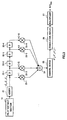
- Fig. 3 is a block diagram showing an internal configuration of the noise power estimation section 15 in a conventional apparatus.
- Adder 21 calculates pilot symbol correlated/in-phase added value ( ⁇ i) of a subcarrier i in time orientation using PICH that is output from the pilot extract section 14, and output the calculation results of each of subcarriers to a delay device 22-1 (shown as "D" in figure) and a multiplier 23-1.
- the delay device 22-1 delays ⁇ of respective subcarriers that are output from the adder 21 until next ⁇ is input, and the obtained ⁇ is output to a delaydevice 22-2 and a multiplier 23-2.
- These operations are similarly applied to delay devices 22-2 to 22-4, and these delay devices delays ⁇ i-2 to ⁇ i+1 that are output from the adder 21 (i is defined to be within a range of from 0 to 767) by one, respectively, to output ⁇ to multipliers coupled to each of the delay devices.
- i is defined to be within a range of from 0 to 767
- the multipliers 23-1 to 23-4 contains predetermined coefficients that are logically calculated beforehand, and respective predetermined coefficients are multiplied to ⁇ that are respectively input, and is output to the adder 24.
- the adder 24 adds four ⁇ input therein, and outputs to a square device 25.
- the square device 25 calculates squares of values that are output from the adder 24 to calculate the noise powers of respective subcarriers.
- a cumulative adder 26 performs cumulative-addition on noise powers of respective subcarriers that are output from the square device 25, and output the results of the cumulative-additions to a multiplier 27.
- Multiplier 27 multiplies predetermined coefficients to the added values that are output from the cumulative adder 26 to calculate "N+I other ".
- Fig. 4 is a diagram, showing PICH with its relation between time and subcarrier.
- Nc is number of the employed subcarriers.
- the signs r i,j is a correlation value of received signal of PICH symbol j of subcarrier i, and scramble code and pilot symbol pattern are removed therefrom.
- PICH transmitted from subcarrier 1 are r 1,0 , r 1,1 , r 1,2 , r 1,3 .
- pilot symbol correlated/ in-phase added values in time orientation ( ⁇ ) is obtained for respective subcarriers by using r i,j . More specifically, the values are obtained by the following formula:
- ⁇ i calculated in the adder 21 is transmitted to delay devices 22-1 and multiplier 23-1 consecutively.
- ⁇ i-0.5 and ⁇ i+0.5 are the averaged values of respective ⁇ of subcarrier number i-1 and i and subcarrier number i and i+1. Assuming that the condition is free of noise and the correlation between adjacent subcarriers is 1, the value obtained by subtracting ⁇ i+0.5 from ⁇ i-0.5 becomes zero. Therefore it is considered that the values obtained as differences are noise component.
- correlations between adjacent subcarrier waves are not necessarily be 1 for subcarriers i-1 to i+1, and thus there may be a case that a difference in channel variation h is generated.
- h ⁇ i-1 is a value obtained by averaging ⁇ for the plurality of subcarriers adjacent to subcarrier i-1, and can be obtained by the following formula (7):
- Formula (11) presents an arithmetic operation conducted in the square device 25, and, in practice, calculation is carried out by replacing n with ⁇ .
- ⁇ ' i 1 8 2
- coefficients of respective ⁇ are the coefficients that are set by multipliers 23-1 to 23-4, respectively. In other words, a part of the calculation using formula (12) is conducted in these multipliers. The results by the calculation within the square device 25 is output to the cumulative adder 26.
- An object of the present invention is to provide a method for estimating noise power and a noise power estimation apparatus, which provide improvement in the estimation accuracy of the noise power, even if the correlation between adjacent subcarriers is low due to the frequency selective fading.
- the above-described object is achieved by repeatedly correcting differences in the channel variations in different subcarriers for multiple times when noise power per one frame ("N+I other ") is estimated.
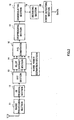
- Fig. 5 is a block diagram, showing an internal configuration of a noise power estimation section according to the first embodiment of the present invention.
- same numeral number as in Fig. 3 is assigned to an element that is commonly appeared in Fig. 3, and the detailed explanation thereof is omitted.
- the point that Fig. 5 is different from Fig. 3, is that the number of the delay devices and the multipliers are respectively increased, and coefficients for multipliers 202-1 to 202-6 and a multiplier 203 are changed.
- An adder 21 calculates pilot symbol correlated / in-phase addition value ( ⁇ i ) in time orientation of subcarrier i using PICH that is output fromapilot extract section 14, and the calculated results for respective subcarriers are output to a delay device (indicated by "D" in the figure) 201-1 and a multiplier 202-1.
- Predetermined coefficients are set in advance, and the multipliers 202-1 to 202-6 multiply predetermined coefficients to ⁇ that are respectively input, and the multiplied values are output to the adder 24.
- the multiplier 203 multiplies 4/((N c - 6) ⁇ ) to values that are output from a cumulative adder 26 to calculate "N+I other ".
- Nc is the number of the employed subcarriers
- ⁇ is a constant.
- Coefficients set for multipliers 202-1 to 202-6 are same as coefficients of respective ⁇ presented by formula (19), and values of the coefficients reflect the twice-corrections. Further, the adding operation for ⁇ is conducted in the adder 24, and the added value is squared in a square device 25.
- errors generated by the channel variations can be diminished by introducing corrections twice during the process for estimating noise power, and thus the estimation accuracy of the noise power can be achieved, even if the correlations between adjacent subcarriers are decreased due to the frequency selective fading.
- the first embodiment illustrates the case of using ⁇ that are obtained by averaging ⁇ of adjacent two subcarriers when noise power per one subcarrier is calculated
- the second embodiment will illustrate a case of using ⁇ that are obtained by averaging ⁇ of adjacent four subcarriers.
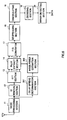
- Fig. 6 is a block diagram showing configuration of receiving system according to the second embodiment of the present invention.
- same numeral number as in Fig. 2 is assigned to an element that is commonly appeared in Fig. 2, and the detailed explanation thereof is omitted.
- a delay spread determination section 201 generates a delay profile on the basis of signal (received signal) that is output from a radio processing section 11 to measure a level of a spreading of multipath (Delay Spread).
- the measurement results represent conditions of frequency selective fading, and levels of the correlations of the adjacent subcarriers can be judged by using thereof.
- the delay spread determination section 201 determines levels of the correlations of the adjacent subcarriers based on the measurement results, and output the evaluation results to the noise power estimation section 202.
- the noise power estimation section 202 changes number of ⁇ employed for the averaging operation, based on the evaluation results by the delay spread determination section 201. In other words, when the correlations between the subcarriers are high, the accuracy for the estimation of the noise power is improved by increasing number of ⁇ employed for the averaging operation. On the other hand, when the correlations between subcarriers are low, an increase of the error caused by the differences of the channel variations canbe prevented by reducing number of ⁇ employed for the averaging operation. In the second embodiment, as compared with the first embodiment, the correlations between subcarriers are set to be higher, and number of ⁇ employed for the averaging operation is increased to 4.
- Fig. 7 is a block diagram showing an internal configuration of the noise power estimation section 202 according to the second embodiment of the present invention.
- same numeral number as in Fig. 5 is assigned to an element that is commonly appeared in Fig. 5, and the detailed explanation thereof is omitted.
- the point that Fig. 7 is different from Fig. 5, is that the adder 21 is replaced by an adder 301, number of the delay devices and the multipliers are respectively increased, and coefficients for multipliers 303-1 to 303-12 and a multiplier 304 are changed.
- a correction is further introduced to formula (29), for the purpose of reducing an influence thereto by the channel variation components, in consideration of frequency selective fading.
- [formula 30] ⁇ " i 1 32 2
- Coefficients set for multipliers 303-1 to 303-12 are same as coefficients of respective ⁇ presented by formula (34), and values of the coefficients reflect the twice corrections. Further, adding operation for ⁇ is conducted by the adder 24, and the added values are squared in the square device 25.
- errors generated by the channel variations can be diminished by introducing corrections twice during the process for estimating noise power, when ⁇ of adjacent four subcarriers are averaged in the calculation for obtaining noise power per one subcarrier, and thus the estimation accuracy of the noise power can be achieved, even if the correlation between adjacent subcarriers is decreased due to the frequency selective fading.
- the third embodiment will illustrate a case of conducting the correcting operations for three times during the process for estimating noise power.
- Fig. 8 is block diagram showing an internal configuration of a noise power estimation section according to the third embodiment of the present invention.
- same numeral number as in Fig. 5 is assigned to an element that is commonly appeared in Fig. 5, and the detailed explanation thereof is omitted.
- the point that Fig. 8 is different from Fig. 5, is that the number of the delay devices and the multipliers are respectively increased, and coefficients for multipliers 402-1 to 402-8 and a multiplier 403 are changed.
- Arithmetic operations provided by the noise power estimation section shown in Fig. 8 will be described using formula. Here, specific arithmetic operations will be described focusing on a subcarrier i. However, since the operations until formula (16) is derived in this example is the same as in the first embodiment, description will be made for operations after obtaining formula (16).
- Coefficients set for multipliers 402-1 to 402-8 are same as coefficients of respective ⁇ presented by formula (38), and values of the coefficients reflect the corrections conducted for three times. Further, adding operation for ⁇ is conducted by the adder 24, and the added value is squared in a square device 25.
- the estimation accuracy of the noise power can further be achieved, by adding corrections conducted for three times during the process for estimating noise power.
- the fourth embodiment will illustrate a case of conducting the correcting operations for three times during the process for estimating noise power in the case of using ⁇ that are obtained by averaging ⁇ of adjacent four subcarriers.
- Fig. 9 is block diagram showing an internal configuration of a noise power estimation section according to the fourth embodiment of the present invention.
- same numeral number as in Fig. 5 is assigned to an element that is commonly appeared in Fig. 5, and the detailed explanation thereof is omitted.
- the point that Fig. 9 is different from Fig. 5, is that the number of the delay devices and the multipliers are respectively increased, and coefficients for multipliers 502-1 to 502-16 and a multiplier 503 are changed.
- Coefficients set for multipliers 502-1 to 502-16 are same as coefficients of respective ⁇ presented by formula (42), and values of the coefficients reflect the corrections conducted for three times. Further, adding operation for ⁇ is conducted by the adder 24, and the added value is squared in a square device 25.
- the estimation accuracy of the noise power can further be achieved, by conducting corrections for three times during the process for estimating noise , in the case of using ⁇ that are obtained by averaging ⁇ of adjacent four subcarriers when noise power of subcarrier is calculated.
- the second embodiment illustrates a case of adjusting number of subcarrier employed in the averaging operation, or in other words, a case of adjusting number of pilots arranged along the frequency orientation, based on the measurement result of a delay spread, which is measured by estimating the condition of frequency selective fading
- the fifth embodiment of the present invention will illustrate a case of adjusting number of pilots arranged along the time orientation employed in the averaging operation.
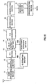
- Fig. 10 is a block diagram showing a configuration of a receiving system according to the fifth embodiment of the present invention.
- same numeral number as in Fig. 6 is assigned to an element that is commonly appeared in Fig. 10 and Fig. 6, and the detailed explanation thereof is omitted.
- the point that Fig. 10 is different fromFig. 6, is that the delay spread determination section 201 is replaced with a fD estimation section 1001 and that the noise power estimation section 202 is replaced with a noise power estimation section 1002.
- the fD estimation section 1001 estimates Doppler frequency based on signal (received signal) that is output from a radio processing section 11, and the estimated Doppler frequency is output to the noise power estimation section 1002.
- the noise power estimation section 1002 changes number of PICH arranged along the time orientation employed for the in-phase adding operation, on the basis of the estimated results obtained by the fD estimation section 1001. More specifically, since the drift of fading is gradual when Doppler frequency is lower, and thus the accuracy for estimating noise power can be improved by increasing number of PICH arranged along the time orientation employed in the in-phase adding operation. On the contrary, since the drift of fading is intense when Doppler frequency is higher, an increase of the error generated by the difference in channel variation can be prevented by decreasing number of PICH arranged along the time orientation employed in the in-phase adding operation.
- number of PICH arranged along the time orientation employed in the in-phase adding operation is changed based on Doppler frequency, so that the influence to the fading is reduced, and the accuracy for estimating noise power is further improved.
- the accuracy for estimating the noise power can be improved by repeatedly correcting for multiple times the differences in the channel variations in the different subcarriers when noise power is estimated, even if the correlation between adjacent subcarriers is low due to the frequency selective fading.
- each of the above preferred embodiments describes that corrected values of noise power per one subcarrier, which are obtained for the whole subcarrier wave, are cumulative-added, and the obtained values are averaged to estimate noise power
- the present invention is not limited thereto, and corrected values of noise power per one subcarrier, which are obtained for a desired subcarrier, may also be cumulative-added, and the obtained values may be averaged by using the desired subcarrier.
- the multiplex system for pilot signal (PICH) described in each of the embodiments stated above may be any multiplex system, such as time multiplex, frequencymultiplex, scatteredmultiplex, code multiplex and the like.
- the method for estimating noise power and the noise power estimation apparatus of the present invention may be applied to Multiple Input Multiple Output - Orthogonal Frequency Division Multiplexing (MIMO-OFDM) or transmission diversity. It is considered that, in the MIMO-OFDM or the transmission diversity, there are basically a lot of scatters, and the propagation paths for each of the antenna are influenced by highly-selective fading, and thus received power considerably fluctuates between subcarriers.
- MIMO-OFDM Multiple Input Multiple Output - Orthogonal Frequency Division Multiplexing
- the estimation accuracy of noise power can be improved by applying method for estimating noise power and the noise power estimation apparatus of the present invention.
- the present invention is preferable to be applied to a radio receiver.
Landscapes
- Engineering & Computer Science (AREA)
- Computer Networks & Wireless Communication (AREA)
- Signal Processing (AREA)
- Quality & Reliability (AREA)
- Physics & Mathematics (AREA)
- Electromagnetism (AREA)
- Noise Elimination (AREA)
Abstract
Description

[formula 2]
[formula 4]
[formula 5]
[formula 6]

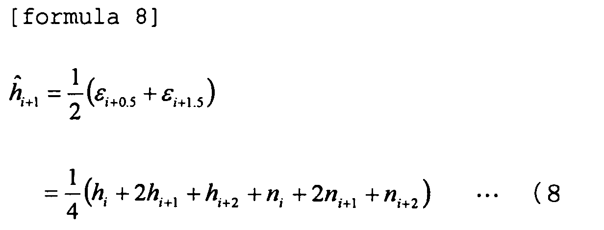
[formula 9]
[formula 10]
[formula 11]
[formula 12]
[formula 13]
[formula 14]

[formula 15]
[formula 16]
[formula 17]
[formula 18]
[formula 19]
[formula 20]
[formula 21]

[formula 22]
[formula 24]
[formula 25]
[formula 26]
[formula 27]



[formula 29]
[formula 30]
[formula 31]
[formula 32]
[formula 33]
[formula 34]
[formula 35]
[formula 36]

[formula 37]
[formula 38]
[formula 39]
[formula 40]

[formula 41]
[formula 42]
[formula 43]
[formula 44]

Claims (6)
- A method for estimating noise power, comprising:averaging correlated values of known signal arranged in a plurality of subcarrier waves;calculating noise power per one subcarrier wave using the averaged values of the correlated values of said known signal;correcting calculation error of said noise power generated by difference of channel variation between subcarrier waves for multiple times based on said known signal;cumulative-adding values of noise power per one subcarrier wave, which are corrected in desired subcarrier wave band; andaveraging thereof by multiplying a predetermined value to the value obtained by the cumulative-adding operation to estimate noise power.
- The method for estimating noise power according to claim 1, further comprising:correcting calculation error of said noise power per one subcarrier wave generated by difference of channel variation between subcarrier waves, using an average value of the correlated value of said known signal in the subcarrier wave in question; andfurther repeatedly correcting an error generated by said correction.
- The method for estimating noise power according to claim 1, wherein number of a plurality of employed adjacent subcarrier waves is variable when the averaging operation for the correlated values of said known signal in a plurality of adjacent subcarrier waves is conducted.
- The method for estimating noise power according to claim 3, further comprising:wherein number of said employed plurality of adj acent subcarrier waves is increased when the correlation between adjacent subcarrier waves is high, andmeasuring a level of spreading of the multipath based on the received signal;determining a level of the correlationbetween adj acent subcarrier waves by the level of the measured spreading of the multipath,
wherein number of said employed plurality of adj acent subcarrier waves is decreased when the correlation between adjacent subcarrier waves is low. - The method for estimating noise power according to claim 1, further comprising:wherein number of employed known signal arranged along the time orientation is increased when estimated Doppler frequency is low,estimating Doppler frequency based on the received signal,
wherein number of employed known signal arranged along the time orientation is decreased when estimated Doppler frequency is high, and
wherein the value obtained by in-phase adding the correlated value of a plurality of known signals in each of subcarrier waves is employed as a correlated value of said known signal. - A noise power estimation apparatus, comprising:wherein said first multiplying means has a predetermined coefficient reflecting a result, which is obtained by correcting for multiple times a calculation error of noise power per one subcarrier wave generated by a difference in a channel variation between subcarrier waves based on said known signal.a known signal-extracting means for extracting known signal from signal transmitted by using a plurality of subcarrier waves from a communication partner;a first multiplying means for multiplying respective predetermined coefficients to correlated values of said known signal between a plurality of adjacent subcarrier waves;a square means for calculating noise power per one subcarrier wave by squaring after adding said multiplying result;a cumulative-adding means for cumulative-adding noise power per one subcarrier wave calculated by said square means for desired subcarrier waves; anda second multiplying means for multiplying a predetermined value to the cumulative-added value calculated by said cumulative-adding means to obtain an averaging value,
Applications Claiming Priority (3)
| Application Number | Priority Date | Filing Date | Title |
|---|---|---|---|
| JP2003038935 | 2003-02-17 | ||
| JP2003038935 | 2003-02-17 | ||
| PCT/JP2004/001633 WO2004073223A1 (en) | 2003-02-17 | 2004-02-16 | Noise power estimation method and noise power estimation device |
Publications (2)
| Publication Number | Publication Date |
|---|---|
| EP1596516A1 true EP1596516A1 (en) | 2005-11-16 |
| EP1596516A4 EP1596516A4 (en) | 2014-12-10 |
Family
ID=32866414
Family Applications (1)
| Application Number | Title | Priority Date | Filing Date |
|---|---|---|---|
| EP04711486.3A Withdrawn EP1596516A4 (en) | 2003-02-17 | 2004-02-16 | METHOD FOR ESTIMATING NOISE POWER AND NOISE POWER ESTIMATING DEVICE |
Country Status (5)
| Country | Link |
|---|---|
| US (1) | US7532864B2 (en) |
| EP (1) | EP1596516A4 (en) |
| JP (1) | JP4283805B2 (en) |
| CN (1) | CN100574162C (en) |
| WO (1) | WO2004073223A1 (en) |
Cited By (1)
| Publication number | Priority date | Publication date | Assignee | Title |
|---|---|---|---|---|
| EP1962449A4 (en) * | 2005-12-12 | 2014-07-02 | Zte Corp | SYSTEM AND METHOD FOR ADJUSTING AMPLITUDE OF DECODED CHANNEL DATA IN A CODE DIVISION MULTIPLE ACCESS (CDMA) SYSTEM |
Families Citing this family (22)
| Publication number | Priority date | Publication date | Assignee | Title |
|---|---|---|---|---|
| KR100505694B1 (en) * | 2003-07-09 | 2005-08-02 | 삼성전자주식회사 | Apparatus for direct measurement of the channel state for the coded orthogonal frequency division multiplexing receiver and method thereof |
| EP1783940A1 (en) * | 2004-09-28 | 2007-05-09 | Matsushita Electric Industrial Co., Ltd. | Multicarrier communication apparatus and multicarrier communication method |
| JP4813463B2 (en) * | 2005-03-14 | 2011-11-09 | シャープ株式会社 | Multi-carrier signal receiver and multi-carrier signal receiving method |
| JP4824016B2 (en) * | 2005-03-15 | 2011-11-24 | 富士通株式会社 | Communication apparatus and communication method |
| JP4510712B2 (en) * | 2005-07-15 | 2010-07-28 | シャープ株式会社 | Multi-carrier signal receiver and multi-carrier signal receiving method |
| WO2007108044A1 (en) * | 2006-03-15 | 2007-09-27 | Matsushita Electric Industrial Co., Ltd. | Base station, radio terminal device, and communication system |
| US7835432B2 (en) * | 2006-04-19 | 2010-11-16 | Beceem Communications Inc | Measuring noise power at wireless receivers using pilot symbol information |
| JP2007295257A (en) * | 2006-04-25 | 2007-11-08 | Mitsubishi Electric Corp | Noise power calculation means and S / N estimation means |
| CN101060511B (en) * | 2006-06-22 | 2011-08-24 | 华为技术有限公司 | OFDM system interference detection method and system |
| CN101496325B (en) * | 2006-07-25 | 2012-07-04 | 富士通株式会社 | Interference noise estimation method, reception processing method, interference noise estimation device and receiver in multi-carrier communication system |
| JP5013771B2 (en) * | 2006-08-10 | 2012-08-29 | 日本放送協会 | MIMO-OFDM noise power measurement method and receiver |
| JP4902333B2 (en) * | 2006-12-11 | 2012-03-21 | 三洋電機株式会社 | Receiving method and receiving apparatus and receiving system using the same |
| WO2009125599A1 (en) * | 2008-04-10 | 2009-10-15 | パナソニック株式会社 | Receiving apparatus, receiving method, integrated circuit, digital television receiver, and program |
| CN101626354B (en) * | 2009-05-20 | 2013-06-05 | 高拓讯达(北京)科技有限公司 | Noise estimation method and noise estimation device of multipath channel |
| US8175630B2 (en) * | 2009-07-10 | 2012-05-08 | Telefonaktiebolaget L M Ericsson (Publ) | Method of closed loop power control adjusted by self-interference |
| CN103250357B (en) * | 2010-10-11 | 2016-08-17 | 英特尔公司 | The uplink noise of virtual MIMO is estimated |
| TW201238260A (en) * | 2011-01-05 | 2012-09-16 | Nec Casio Mobile Comm Ltd | Receiver, reception method, and computer program |
| US8675720B2 (en) * | 2011-06-30 | 2014-03-18 | Intel Corporation | Noise estimation filter |
| CN103891168B (en) * | 2011-10-19 | 2018-04-27 | 马维尔国际贸易有限公司 | For suppressing the system and method by the interference in the equipment received signal with two or more antennas |
| WO2013059566A1 (en) | 2011-10-20 | 2013-04-25 | Marvell World Trade Ltd. | Systems and methods for suppressing interference in a wireless communication system |
| US8831530B2 (en) | 2012-04-30 | 2014-09-09 | Samsung Electronics Co., Ltd. | Communication system with transmission power estimation mechanism and method of operation thereof |
| US9071474B1 (en) | 2013-07-25 | 2015-06-30 | Marvell International Ltd. | Systems and methods for suppressing interference in a wireless communication system |
Family Cites Families (13)
| Publication number | Priority date | Publication date | Assignee | Title |
|---|---|---|---|---|
| US5572552A (en) * | 1994-01-27 | 1996-11-05 | Ericsson Ge Mobile Communications Inc. | Method and system for demodulation of downlink CDMA signals |
| DE19738780A1 (en) * | 1997-09-04 | 1999-03-11 | Thomson Brandt Gmbh | Method and circuit arrangement for correcting phase and / or frequency errors of digital multicarrier signals |
| US6442222B1 (en) * | 1998-12-24 | 2002-08-27 | At&T Wireless Services, Inc. | Method for error compensation in an OFDM system with diversity |
| US6879577B2 (en) * | 1998-12-31 | 2005-04-12 | Lg Electronics Inc. | Method and apparatus for determining frame quality in mobile communication system |
| US7072381B2 (en) * | 1999-12-28 | 2006-07-04 | Ntt Docomo, Inc. | Path search method, channel estimation method and communication device |
| EP1176750A1 (en) * | 2000-07-25 | 2002-01-30 | Telefonaktiebolaget L M Ericsson (Publ) | Link quality determination of a transmission link in an OFDM transmission system |
| US6542483B1 (en) * | 2000-11-08 | 2003-04-01 | Motorola, Inc. | Method and an apparatus for Eb/Nt estimation for forward power control in spread spectrum communications systems |
| JP4048111B2 (en) * | 2001-12-28 | 2008-02-13 | 株式会社エヌ・ティ・ティ・ドコモ | Reception device, transmission device, communication system, and communication method |
| CA2415170C (en) * | 2001-12-28 | 2008-07-15 | Ntt Docomo, Inc. | Receiver, transmitter, communication system, and method of communication |
| US7010017B2 (en) * | 2002-01-30 | 2006-03-07 | Qualcomm Inc. | Receiver noise estimation |
| JP4043287B2 (en) * | 2002-05-24 | 2008-02-06 | 三菱電機株式会社 | Wireless communication system, communication apparatus, and reception quality measuring method |
| US7099270B2 (en) * | 2002-06-06 | 2006-08-29 | Texas Instruments Incorporated | Multi-path equalization for orthogonal frequency division multiplexing communication system |
| US7046963B2 (en) * | 2002-12-06 | 2006-05-16 | Texas Instruments Incorporated | Method and apparatus of signal estimation over generalized fading channel |
-
2004
- 2004-02-16 US US10/524,213 patent/US7532864B2/en not_active Expired - Fee Related
- 2004-02-16 JP JP2005505019A patent/JP4283805B2/en not_active Expired - Fee Related
- 2004-02-16 CN CNB2004800007556A patent/CN100574162C/en not_active Expired - Fee Related
- 2004-02-16 WO PCT/JP2004/001633 patent/WO2004073223A1/en not_active Ceased
- 2004-02-16 EP EP04711486.3A patent/EP1596516A4/en not_active Withdrawn
Cited By (1)
| Publication number | Priority date | Publication date | Assignee | Title |
|---|---|---|---|---|
| EP1962449A4 (en) * | 2005-12-12 | 2014-07-02 | Zte Corp | SYSTEM AND METHOD FOR ADJUSTING AMPLITUDE OF DECODED CHANNEL DATA IN A CODE DIVISION MULTIPLE ACCESS (CDMA) SYSTEM |
Also Published As
| Publication number | Publication date |
|---|---|
| CN100574162C (en) | 2009-12-23 |
| WO2004073223A1 (en) | 2004-08-26 |
| CN1701547A (en) | 2005-11-23 |
| EP1596516A4 (en) | 2014-12-10 |
| JPWO2004073223A1 (en) | 2006-06-01 |
| US7532864B2 (en) | 2009-05-12 |
| JP4283805B2 (en) | 2009-06-24 |
| US20060154608A1 (en) | 2006-07-13 |
Similar Documents
| Publication | Publication Date | Title |
|---|---|---|
| US7532864B2 (en) | Noise power estimation method and noise power estimation device | |
| KR100318588B1 (en) | Wireless communication apparatus and wireless communication method | |
| EP1172956B1 (en) | OFDM packet communication receiver | |
| EP1589681B1 (en) | Fading frequency estimation apparatus | |
| US7672221B2 (en) | Radio receiver and radio signal receiving method | |
| US7627059B2 (en) | Method of robust timing detection and carrier frequency offset estimation for OFDM systems | |
| EP1856811B1 (en) | Method and apparatus for synchronizing wireless receiver | |
| US20030152178A1 (en) | Mobile communication system, channel synchronization establishing method, and mobile station | |
| EP1235360A1 (en) | Communication terminal apparatus and demodulation method | |
| EP1210803B1 (en) | Determination of data rate, based on power spectral density estimates | |
| KR100737773B1 (en) | Channel estimation device, channel estimation method and wireless receiver | |
| JP4154570B2 (en) | Method and wireless LAN receiver for determining a tuning frequency offset in a receiver that generates complex data samples from a demodulated received signal | |
| EP2031790A1 (en) | Estimating a signal-to-interference ration in a receiver of a wireless communications system | |
| US7508862B2 (en) | Determination and selection of transmission paths as a function of the operating situation for setting up rake fingers for rake receiver units in mobile communication terminals | |
| US7154955B2 (en) | Multi-carrier transmission system and associated method of reducing the effect of multi-path interference | |
| JP2000049662A (en) | Demodulation circuit in CDMA receiver | |
| KR100355327B1 (en) | Communication terminal apparatus and radio communication method | |
| EP1280282B1 (en) | Apparatus and method for measuring SIR in a Rake-receiver | |
| US9490867B2 (en) | CDMA communications device and related methods | |
| EP1906544A2 (en) | Code synchronization method and receiver | |
| CN101099322A (en) | Transmission method and transmission device for OFDM-CDMA communication system | |
| EP1454421A1 (en) | Interference suppression in a cdma radio receiver | |
| KR101346436B1 (en) | Apparatus and method of estimating channel using adaptive channel estimation window in wireless communication based on CAZAC sequence | |
| CN118302961A (en) | Communication device, communication system, communication method, control circuit and storage medium | |
| JP2003218737A (en) | Path detection device |
Legal Events
| Date | Code | Title | Description |
|---|---|---|---|
| PUAI | Public reference made under article 153(3) epc to a published international application that has entered the european phase |
Free format text: ORIGINAL CODE: 0009012 |
|
| 17P | Request for examination filed |
Effective date: 20050316 |
|
| AK | Designated contracting states |
Kind code of ref document: A1 Designated state(s): AT BE BG CH CY CZ DE DK EE ES FI FR GB GR HU IE IT LI LU MC NL PT RO SE SI SK TR |
|
| AX | Request for extension of the european patent |
Extension state: AL LT LV MK |
|
| DAX | Request for extension of the european patent (deleted) | ||
| RBV | Designated contracting states (corrected) |
Designated state(s): DE GB |
|
| A4 | Supplementary search report drawn up and despatched |
Effective date: 20141106 |
|
| RIC1 | Information provided on ipc code assigned before grant |
Ipc: H04B 17/00 20060101AFI20141031BHEP |
|
| STAA | Information on the status of an ep patent application or granted ep patent |
Free format text: STATUS: THE APPLICATION IS DEEMED TO BE WITHDRAWN |
|
| 18D | Application deemed to be withdrawn |
Effective date: 20150901 |